Multi 55N - Pump ESPA - Free user manual and instructions
Find the device manual for free Multi 55N ESPA in PDF.
| Product type | Vertical multistage centrifugal pump |
| Brand | ESPA |
| Model | Multi 55N |
| Category | Pump |
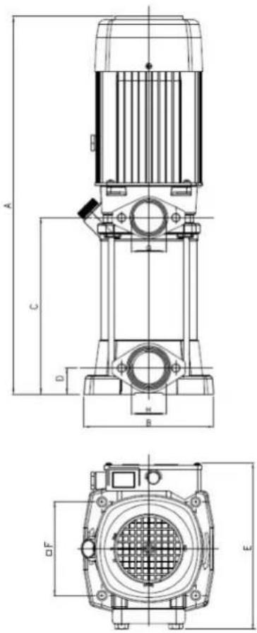
| Dimensions (L × W × H) | 531 × 184 × 245 mm |
| Weight | 25.7 kg |
| Power supply | Single-phase 220 V / Three-phase 380 V (depending on version) |
| Absorbed power (P1) | 2.1 kW |
| Nominal current (single/three) | 9.6 A / 6.6 A |
| Capacitor | 30 μF |
| Max flow | 333 l/min |
| Max head | 38 m |
| Max working pressure | 1.2 MPa |
| Max liquid temperature | 40 °C |
| Ambient temperature | 0 °C to 40 °C |
| Protection rating | IP55 |
| Efficiency (η) | 52 % |
| Minimum efficiency index (MEI) | ≥ 0.40 |
| Main functions | Pumping clean water, boosting, distribution, irrigation |
| Maintenance and cleaning | Clean with a damp cloth; drain pipes during freezing conditions |
| Safety | Thermal protection, 30 mA differential switch, mandatory earthing |
| Spare parts and repairability | Contact an ESPA Authorized Technical Service; www.espa.com |
| General information | Compliant with CE directives; continuous operation S1 |
Frequently Asked Questions - Multi 55N ESPA
User questions about Multi 55N ESPA
0 question about this device. Answer the ones you know or ask your own.
Ask a new question about this device
Download the instructions for your Pump in PDF format for free! Find your manual Multi 55N - ESPA and take your electronic device back in hand. On this page are published all the documents necessary for the use of your device. Multi 55N by ESPA.
USER MANUAL Multi 55N ESPA
natural_image
Technical line drawing of a mechanical pump or motor assembly (no text or symbols visible)EN Instruction manual.... 10 (Translation from the original Spanish)
EN: EVIDENCE OF CONFORMITY
We declare, under our responsibility, that the products in this manual comply with the following directives and standards:
- Directive 2006/42/EC (Machine Security): Standard EN 809 and EN 60204-1
- Directive EMC 2014/30/EU (Electromagnetic compatibility): Standard EN 61000-6-1 y EN 61000-6-3
- Directive 2014/35/EU (Low voltage): Standard EN 60335-1 and EN 60335-2-41
- Directive 2009/125/EC (ecological design): Regulation (EU) 2019/1781 electrical motors and variable speed drives. Standard EN 60034-30. Regulation 547/2012 for Hydraulic pumps. Standard EN 16480
- Directive 2012/19/EU (on waste electrical and electronic equipment (WEEE)): Standard EN 50419:2006 about marking of electrical and electronic equipment.
- Directive 2011/65/UE (Restriction of hazardous sustances): Standard EN 50581.
FR : DECLARATION DE CONFORMITÉ
EVIDENCE OF CONFORMITY
We declare, under our responsibility, that the products in this manual comply with the following directives and standards:
- Supply of Machinery (Safety) Regulations 2008: Standard BS 809 and BS 60204-1
- Electromagnetic Compatibility Regulations 2016: Standard BS 61000-6-1 and BS 61000-6-3.
- Electrical Equipment (Safety) Regulations 2016: Standard BS 60335-1 and BS 60335-2-41.
- The Ecodesign for Energy-Related Products and Energy Information (Amendment) (EU Exit) Regulations 2019: Standard BS 60034-30.
- The Restriction of the Use of Certain Hazardous Substances in Electrical and Electronic Equipment Regulations 2012. Standard BS 50581.
Banyoles, January 7th 2021
Josep Unyó (Technical Manager)
ESPA 2025, SL
Ctra. de Mieres, s/n – 17820 Banyoles
Girona - Spain
Damage prevention and safety instructions (See figure 4)
| A | Warning! Observe limitations of use. |
| B | The name plate voltage must be the same as the mains voltage. |
| C | Connect the pump to the mains via an omnipolar switch with at least a 3 mm opening between contacts.Install a high-sensitivity differential switch (0.03A) as extra protection against lethal electric shocks. |
| D | If the supply cord is damaged, it must be replaced by an A.T.S. |
| E | Connect the pump to the ground. |
| F | Use pump only within performance limits indicated or the name plate. |
| G | Remember to prime pump. |
| H | Check for motor self-ventilation. |
| I | This apparatus may be used by children 8 years or older and persons with reduced physical, sensory or mental capacities, or lacking experience and knowledge, if they are supervised or receive adequate training on the safe use of the apparatus and understand the dangers.Children should not be allowed to play with the apparatus.Children should not perform the ordinary cleaning and maintenance tasks without supervision. |
| J | Be careful with hazardous liquids and environments. |
| K | Caution! Look out for accidental leaks.Do not expose pump to bad weather. |
| L | Caution! Avoid icing.Cut out power supply before servicing pump. |
Contents
Safety precautions....10
- General information....11
- Handling....11
- Installation ....11
3.1. Fixing....11
3.2. Suction pipe assembly .....11
3.3. Discharge pipe assembly .....11
3.4. Electrical connection .....12
3.5. Pre-start checks ..... 12
- Starting 12
- Maintenance 12
- Disposing of the product....12
- Nameplate 12
- Possible faults, causes and solutions....13
- Technical data ......13
- List of main components....44
11.Wiring diagrams....45 - Illustrations....46
Safety precautions
This symbol together with one of the following words “Danger” or “Warning” indicates the risk level deriving from failure to observe the prescribed safety precautions:

DANGER risk of electric shock
Warns that failure to observe the pre cautions involves a risk of electric shock.

DANGER
Warns that failure to observe the pre cautions involves a risk of damage to persons and/or things.

WARNING
Warns that failure to observe the pre cautions involves the risk of damaging the pump and/or the facility
1. GENERAL INFORMATION
Please observe the following instructions to achieve the best pump performance possible and a trouble free installation.

Read these instructions before installing the pump.
Save them for future reference.
These are vertical multistage centrifugal pumps having more than one impeller assembled in-line. The same flow passes through each impeller but the pressure increases each time, i.e. more impellers, more pressure.
These pumps are designed to operate with clean water, free from particles in suspension and with a maximum temperature of 40 ^ .

Correct pump operation is assured providing the instructions on electrical connection, installation and use are strictly adhered to.

Failure to adhere to the instructions can result in premature failure of the pump and voiding of the warranty.
Minimum efficiency index
With the application of the European Regulation 547/2012, the minimum efficiency index after 01/01/2015 must be MEI ≥ 0.40.
The reference value for the most efficient hydraulic pumps is rated at MEI ≥ 0.70.
The performance curves and efficiency characteristics can be checked on the technical catalogues and on www.espa.com.
The operation of this hydraulic pump with variable operating points can be cheaper and more efficient when controlled with, for example, a speed regulation control that adjusts the pump's operation to the system performance.
The efficiency reference criteria can be found on the following link:
http://global.espa.com/doc-descarrega-1/fingerprints.pdf
2. HANDLING
The pumps are supplied suitably packaged to prevent damage in transit. Before unpacking, check that the packaging has not been damaged or deformed,

Lift and handle the product with care and with the right tools.
3. INSTALLATION
These pumps are designed for indoor use.
Make sure that pump is never submerged and that it rests in a dry and well aired room.
3.1. Fixing
The pump should be installed on a solid, horizontal base, secured by screws or bolts and using the existing holes in the mount.
3.2. Suction pipe assembly
The suction pipe, if longer than 7 meters, must be of the same or greater diameter than the pump inlet and installed in an upward inclination to prevent trapped air pockets forming.
If the pump is required to perform a suction lift, to avoid unnecessary losses of head on the discharge side, the pump should be installed as close as possible to the water.
The end of the suction pipe must always remain at least 30 cm below the water level. (Fig.3)
3.3. Discharge pipe assembly
It is recommended to use pipes with a diameter equal or greater than the pump outlet. This will reduce loss of head caused by friction in longer pipe runs.
Pipework must be supported and their weight must not rest on the pump.
If a foot valve has not been installed it is recommended to fit a check valve to prevent accidental draining down of the system.
3.4. Electrical connection

The electrical installation must have a multi-pole isolator with minimum 3 mm contact openings. The protection of the system will be based on a differential switch ( fn = 30 mA )
The power cable must correspond at least to the type H05 RN-F (according to 60245 IEC 57) and having terminals.
The connection and its dimensioning must be performed by a qualified installer according to the needs of the facility and following the regulations in force in each country.

Pump models 25: Single-phase motors have thermal protection.
The rest of the pump models with single phase motor and all three phase motor pumps do not incorporate this protection. They must be connected to a motor-protective circuit breaker that can be adjusted manually. Set the circuit breaker according to the current given in the rating plate plus 10%.
Follow instructions given on fig.1 for correct electrical connection.
3.5. Pre-start checks

Ensure the voltage and frequency of the supply corresponds to the values indicated on the electrical data label.
Ensure that the pump shaft is rotating freely.
Fill the pump body with water through the self-priming plug opening. If a foot valve has been installed, also fill the suction pipe.
Check all joints and connections for leaks.
THIS PUMP MUST NEVER BE DRY RUN.
4. STARTING
Ensure all valves in the pipework are open.
Connect power supply. There will be a delay before water appears at the end of the discharge pipe.
Viewings from the fan ensure that the rotation of the motor is clockwise. On three phase pumps the motor may rotate anticlockwise. If this is happening, the flow will be lower than expected. To rectify this situation the two supply phases need to be reversed.
Ensure that the absorbed current is the same or lower than the maximum shown on the name plate. Adjust the thermal relay if is necessary.
If the pump fails to operate refer to the possible faults, causes and solutions list for assistance.
5. MAINTENANCE
Under normal conditions these pumps require no special or planned maintenance.
Clean the pump with a damp cloth without using harsh products.

If the pump is not to be operated for a long period it is recommended to remove it from the installation, drain down and store in a dry, well ventilated place.
ATTENTION: In the event of faults or damage occurring to the pump, repairs should only be carried out by an authorised service agent.
The Official Technical Services list is in www.espa.com.
6. DISPOSING OF THE PRODUCT
When the pump is eventually disposed of, please note that it contains no toxic or polluting material. All main components are material identified to allow selective disposal.
This product or parts of it must be disposed of in an environmentally sound way, use the waste collection service. If this is not possible, contact the nearest ESPA service workshop.
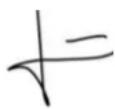
- PLATE SHOWING CHARACTERISTICS
text_image
MULTI35 5 N 230/400 50 1200/STD Q(l/min): 33-165 Hmin: 22m Tmax: 40°C H(m): 65-22 Hmax: 70m P2: 1.5kW Δ230V/Y400V 3~50Hz I:6.9/4A P1: 2.2kW 1.5kW IE2 - 83% IP-55 MEI ≥ 0,40 (η = -.) ESPA 2025 S.L. 17820 Banyoles (MADE IN SPAIN) Is.KL.F S1 DESCRIPTION| 1 | Item reference |
| 2 | Voltage + frequency + item specifications |
| 3 | Flow |
| 4 | Pressure |
| 5 | Nominal voltage, no. stages, alternate current symbol and frequency |
| 6 | Energy efficiency index (Three-phase model) |
| 6 | Capacitor (Single-phase model) |
| 7 | EC mark |
| 8 | Humidity protection level |
| 9 | Minimum working pressure |
| 10 | Maximum pressure |
| 11 | Year and week of manufacture + Pump serial number |
| 12 | Max. liquid temperature |
| 13 | Motor max. nominal output (P2) |
| 14 | Electric pump unit absorbed power (P1) |
| 15 | Minimum Efficiency Index |
| 16 | Designated motor insulation |
| 17 | Continuous operation symbol |
| 18 | Maximum nominal intensity at nominal voltage |
| 19 | Name and address of vendor responsible for the product |
8. POSSIBLE FAULTS, CAUSES AND SOLUTIONS
1) The motor does not start.
2) Motor operates but there is no pressure.
3) Motor over-heating.
4) Pump does not deliver rated capacity.
5) Motor starts and stops automatically.
6) Shaft rotates with difficulty.
| 1 | 2 | 3 | 4 | 5 | 6 | POSSIBLE PROBLEM | SOLUTIONS |
| X | X | Pump blocked | Disconnect it and take it to the official Technical Service | ||||
| X | Foot valve clogged | Clean it or replaced by new one | |||||
| X | X | Total head higher than expected | Verify geometric head and loss of head | ||||
| X | X | X | Wrong tension | Check that the tension is the same as that on the name plate | |||
| X | X | Water level in well or tank has come down | Verify suction head | ||||
| X | Fuse or thermal relay disconnected | Change fuse or thermal relay | |||||
| X | X | Impellers are worn out | Disconnect pump and take it to your Service Dealer | ||||
| X | Foot valve not submerged | Be sure suction pipe is submerged | |||||
| X | Pump was not primed | Fill pump body with water | |||||
| X | X | Room not properly aired | Provide good ventilation | ||||
| X | Air entry | Seal unions and joints properly |
9. TECHNICAL DATA
Liquid temperature... 4°C - 40°C
Ambient temperature: 0°C - 40°C
Storage temperature: -10°C - 50°C
Ambient relative humidity, max.: 95%
Motor class I.
Other data see Figure 2.
6. AFVOEREN VAN HET PRODUCT
EN List of main components
text_image
Technical schematic diagram of a mechanical device with numbered components for identification.| ES | EN | FR | DE | IT | |
| 1 | Tapa ventilador | Fan cover | Capot ventilateur | Lüfterhaube | Cuffia ventola |
| 2 | Ventilador | Fan | Ventilateur | Lüfterrad | Ventola |
| 3 | Rodamiento | Bearing | Roulement | Wälzlager | Cuscinetto |
| 4 | Estátor | Stator | Stator | Ständer | Statore |
| 5 | Eje motor | Motor axle | Axe moteur | Motorwelle | Asse del motore |
| 6 | Rodamiento | Bearing | Roulement | Wälzlager | Cuscinetto |
| 7 | Cuerpo impulsión | Delivery body | Corps de refoulement | Drukgehäuse | Corpo premente |
| 8 | Retén mecánico | Mechanical seal | Garniture mécanique | Rückhalter | Tenuta meccanica |
| 9 | Tapón cebado | Priming plug | Bouchon de remplissage | Einfüllstopfen | Tappo di riempimento |
| 10 | Rodete | Impeller connector | Roue | Läufer | Girante |
| 11 | Difusor | Diffuser | Diffuseur | Diffusor | Diffusore |
| 12 | Cuerpo aspiración | Suction body | Corps d'aspiration | Saugehäuse | Corpo di aspirazione |
text_image
Z X Y U V W
400V

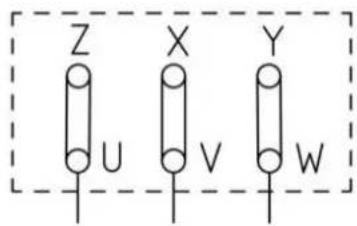
text_image
Z X Y U V W
230V

Fig. 2 / Abb. 2 / Afb. 2 / Puc. 2 / 图 2 / 2
text_image
F E A C D B Etext_image
A B C D E F G H I J K LESPA 2025, S.L.
C/ Mieres, s/n - 17820 BANYOLES
GIRONA – SPAIN
www.espa.com