
HCA92641BH - Range hood BEKO - Free user manual and instructions
Find the device manual for free HCA92641BH BEKO in PDF.
| Product type | Extractor hood |
| Brand | Beko |
| Model | HCA92641BH |
| Width | 896 mm |
| Depth | 393 mm |
| Height (min / max) | 750 mm / 1130 mm |
| Net weight | 13 kg |
| Color | Black |
| Supply voltage | 220 - 240 V, 50 Hz |
| Motor power | 210 W |
| Total power | 216 W |
| Extraction capacity | 648 m³/h |
| Number of speeds | 3 |
| Control type | Electronic push buttons |
| Lighting | 2 x 3 W LED |
| Air outlet diameter | 120 / 150 mm |
| Minimum height above hob | 65 cm |
| Grease filter | Washable aluminium |
| Activated charcoal filter (optional) | Yes, for recirculation |
| Automatic shut-off function | Yes, 15-minute delay |
| Installation type | Wall-mounted with extraction or recirculation |
| Repairability and spare parts | Parts available for 10 years after purchase |
Frequently Asked Questions - HCA92641BH BEKO
User questions about HCA92641BH BEKO
0 question about this device. Answer the ones you know or ask your own.
Ask a new question about this device
Download the instructions for your Range hood in PDF format for free! Find your manual HCA92641BH - BEKO and take your electronic device back in hand. On this page are published all the documents necessary for the use of your device. HCA92641BH by BEKO.
USER MANUAL HCA92641BH BEKO
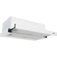
natural_image
Illustration of a kitchen range hood with three circular buttons (no text or symbols)HCA92640BH
HCA92640WH
HCA62640W
HCA62640WH
HCA62640B
HCA62640BH
HCA62540B
HCA92540B
HCA92641WH
HCA92641BH
HCA62641WH
HCA62641BH
EN DE ES FR PL NL CZ
Please read this user manual first!
Dear Customer,
Thank you for preferring a Beko product. We hope that you get the best results from your product which has been manufactured with high quality and state-of-the-art technology. Therefore, please read this entire user manual and all other accompanying documents carefully before using the product and keep it as a reference for future use. If you handover the product to someone else, give the user manual as well. Follow all warnings and information in the user manual.
Remember that this user manual is also applicable for several other models. Differences between models will be identified in the manual.
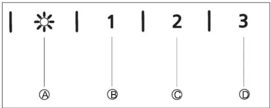
Explanation of symbols
Throughout this user manual the following symbols are used:

Important information or useful hints about usage.

Warning for hazardous situations with regard to life and property.
Warning for electric shock.

This product was manufactured using the latest technology in environmentally friendly conditions.
CONTENTS
ENGLISH 04-19
DEUTSCH 20-37
ESPAÑOL 38-55
FRANÇAIS 56-73
POLSKI 74-91
NEDERLANDS 92-109
ČESKY 110-126
ITALIANO 127-143
SLOVENŠČINA 144-160
SLOVENSKÝ 161-178
УКРАЇНСЬКИЙ 179-196
РУССКИЙ 197-214
ROMÂNĂ 215-231
EESTI 232-248
LIETUVIŲ K 249-265
LATVIJAS 266-283
PORTUGUÊS 284-301
01M-8848793200-0119-06
01M-8848803200-0119-06
01M-8848053200-0119-06
01M-8848773200-0119-06
01M-8848063200-0119-06
01M-8848783200-0119-06
01M-8851123200-0119-06
01M-8851313200-0119-06
01M-8806343200-0119-06
01M-8806353200-0119-06
01M-8806363200-0119-06
01M-8806373200-0119-06
1
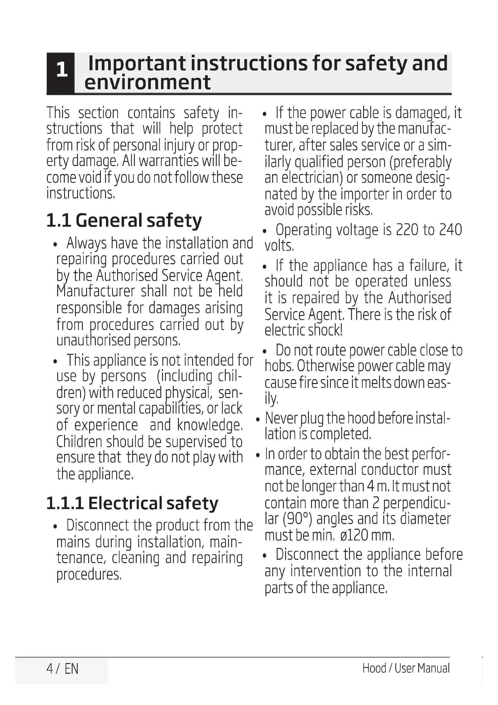
Important instructions for safety and environment
This section contains safety instructions that will help protect from risk of personal injury or property damage. All warranties will become void if you do not follow these instructions.
1.1 General safety
• Always have the installation and repairing procedures carried out by the Authorised Service Agent. Manufacturer shall not be held responsible for damages arising from procedures carried out by unauthorised persons.
- This appliance is not intended for use by persons (including children) with reduced physical, sensory or mental capabilities, or lack of experience and knowledge. Children should be supervised to ensure that they do not play with the appliance.
1.1.1 Electrical safety
- Disconnect the product from the mains during installation, maintenance, cleaning and repairing procedures.
- If the power cable is damaged, it must be replaced by the manufacturer, after sales service or a similarly qualified person (preferably an electrician) or someone designated by the importer in order to avoid possible risks.
- Operating voltage is 220 to 240 volts. - If the appliance has a failure, it should not be operated unless it is repaired by the Authorised Service Agent. There is the risk of electric shock!
- Do not route power cable close to hobs. Otherwise power cable may cause fire since it melts down easily.
- Never plug the hood before installation is completed.
- In order to obtain the best performance, external conductor must not be longer than 4 m. It must not contain more than 2 perpendicular (90°) angles and its diameter must be min. ∅120 mm.
- Disconnect the appliance before any intervention to the internal parts of the appliance.
1
Important instructions for safety and environment
1.1.2 Product safety
- You can use a pipe with a diameter of 120 mm or 150 mm on the flue connection of the hood.
- Do not make connections to the flues connected with stoves, exhaust shafts or flues with rising flames. Observe the rules set by authorities on the discharge of exhaust air.
- The height between the lower surface of the hood and upper surface of the stove/oven should not be less than 65 cm.
- Do not operate the hood without aluminum filters and do not remove the filters while it is operated.
- Never touch the hood's lamp after they operated for a long time. Hot lamps may burn your hand.
- Avoid big flames beneath the product. Otherwise, particles on oil filter may ignite and lead to a fire.
- Turn on the hobs after placing pans or pots on it. Otherwise, rising temperature may deform certain parts of your product.
-
Turn off the hobs before taking away pans or pots.
-
Avoid inflammable materials under the hood.
- Oil may ignite while frying foods. Therefore, be careful about cloths and curtains.
- Never leave the cooker unattended when frying foods; otherwise boiled oil may cause fire.
- There is the risk of fire if your hood is not cleaned in the specified periods.
- Be extremely careful and wear gloves when cleaning the hood.
• We advise you to operate the appliance a few minutes before starting to cook in order to increase the suction power. Thus, you shall have a continuous and stable suction power when the vapors arises. - Operate your hood for 15 minutes more after the end of cooking or frying in order to remove smell cooking vapour in the kitchen.
- When the hood is in use, especially together with gas cookers, make sure that environment is ventilated with clean air.
- Pay attention not to connect the appliance to the flues used by non-electrical devices. (E.g.: Heater flue).
1
Important instructions for safety and environment
- When a non-electrical device is concurrently used in the same room together with the hood, the negative pressure in the room must be maximum 0.4 mbar in order to prevent hood from sucking other device's exhaust into the room.
1.1.3 Children's safety
- Packaging materials are dangerous to children. Keep packaging materials in a safe place out of reach of children.
- Electrical appliances are dangerous to children. Keep children away from the product. Do not allow children play with the appliance.
1.2 Intended use
- This appliance is intended for domestic use. It is not suitable for commercial use and it must not be used out of its intended use.
- The manufacturer shall not be liable for any damage caused by improper use or handling.
- The period required for the availability of spare parts for the correct operation of the appliance is 10 years.
1.3 Compliance with WEEE regulation and disposal of the waste product
This product does not contain harmful and forbidden materials described in the "Directive on the Restriction of the Use of Certain Hazardous Substances in Waste Electrical and Electronic Equipment" (WEEE) issued by the T.R. Ministry of Environment and Urbanization.
Complies with the WEEE Directive.
This product has been manufactured with high quality parts and materials which can be reused and are suitable for recycling. Therefore, do not dispose the product with normal domestic waste at the end of its service life. Take it to a collection point for the recycling of electrical and electronic equipment. Please consult your local authorities to learn the nearest collection point. Help protect the environment and natural resources by recycling used products.
1.4 Package information

Ni-MH
The product package is made of recyclable material as per the National Legislation. Do not dispose of the package waste together with the household waste or other waste and deliver them to the package collection points indicated by the local authority.
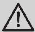
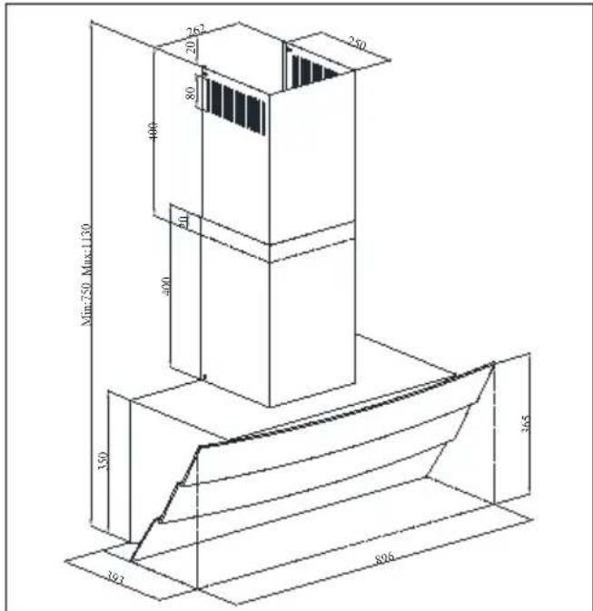
2 Technical specifications of your appliance
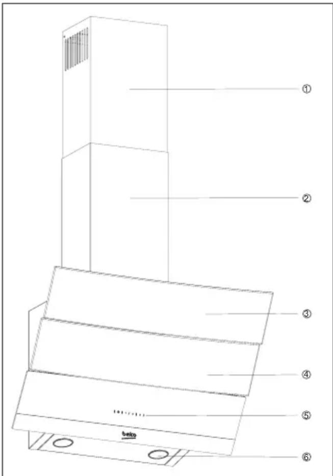
- Internal flue
- External flue
- Glass cover
- Filter (under the glass cover)
- Control panel
- Illumination
(Figure 1)
| HCA 92640 BH | HCA 92640 WH | HCA 62640 W | HCA 62640 WH | |
| Width 896 mm 896 | mm 596 mm 596 mm | |||
| Depth 393 mm 393 | mm 386 mm 386 mm | |||
| Height | 750 mm / 1130 mm | 750 mm / 1130 mm | 750 mm /1080 mm | 750 mm /1080 mm |
| Supply voltage | 220 - 240 V, 50 Hz | 220 - 240 V, 50 Hz | 220 - 240 V, 50 Hz | 220 - 240 V, 50 Hz |
| Control | With 3 levels | With 3 levels | With 3 levels | With 3 levels |
| Lamp power | 2 x 3 W | 2 x 3 W | 2 x 3 W | 2 x 3 W |
| Air outlet pipe | 120 / 150 mm | 120 / 150 mm | 120 / 150 mm | 120 / 150 mm |
| Capacity | 577 m3/h | 577 m3/h | 537 m3/h | 537 m3/h |
| Motor power | 1 x 210 W | 1 x 210 W | 1 x 210 W | 1 x 210 W |
| Total power | 216 W | 216 W | 216 W | 216 W |
| Net weight | 13 kg | 13 kg | 10,4 kg | 10,4 kg |
| Colour | Black | White | White | White |
Values stated on the product labels or in the documentation accompanying it are obtained in laboratory conditions in accordance with relevant standards. These values may vary depending on operational and environmental conditions of the product.
2 Technical specifications of your appliance
| HCA 62640 B HCA 62640 BH HCA 62540 B HCA 92540 B | ||||
| Width 596 mm 596 mm 596 mm 896 mm | ||||
| Depth 386 mm 386 mm 386 mm 393 mm | ||||
| Height 750 mm /1080 mm 750 mm /1080 mm 750 mm /1080 mm 750 mm /1130 mm | ||||
| Supply voltage 220 - 240 V, 50 Hz 220 - 240 V, 50 Hz 220 - 240 V, 50 Hz | ||||
| Control | With 3 levels | With 3 levels | With 3 levels | With 3 levels |
| Lamp power | 2 x 3 W | 2 x 3 W | 2 x 3 W | 2 x 3 W |
| Air outlet pipe | 120 / 150 mm | 120 / 150 mm | 120 / 150 mm | 120 / 150 mm |
| Capacity | 537 m3/h | 537 m3/h | 566 m3/h | 593 m3/h |
| Motor power | 1 x 210 W | 1 x 210 W | 1 x 210 W | 1 x 210 W |
| Total power | 216 W | 216 W | 216 W | 216 W |
| Net weight | 10,4 kg | 10,4 kg | 10,4 kg | 13 kg |
| Colour | Black | Black | Black | Black |
| HCA 62641 BH | HCA 62641 WH | HCA 92641 BH | HCA 92641 WH | |
| Width | 596 mm | 596 mm | 896 mm | 896 mm |
| Depth | 386 mm | 386 mm | 393 mm | 393 mm |
| Height | 750 mm /1080 mm | 750 mm /1080 mm | 750 mm / 1130 mm | 750 mm / 1130 mm |
| Supply voltage | 220 - 240 V, 50 Hz | 220 - 240 V, 50 Hz | 220 - 240 V, 50 Hz | 220 - 240 V, 50 Hz |
| Control | With 3 levels | With 3 levels | With 3 levels | With 3 levels |
| Lamp power | 2 x 3 W | 2 x 3 W | 2 x 3 W | 2 x 3 W |
| Air outlet pipe | 120 / 150 mm | 120 / 150 mm | 120 / 150 mm | 120 / 150 mm |
| Capacity | 638 m3/h | 638 m3/h | 648 m3/h | 648 m3/h |
| Motor power | 1 x 210 W 1 x 210 W | 1 x 210 W | W 1 x 210 W | |
| Total power | 216 W | 216 W | 216 W | 216 W |
| Net weight | 10,4 kg | 10,4 kg | 13 kg | 13 kg |
| Colour | Black | White | Black White |
3 Installing your appliance
Please consult the nearest Authorised Service Agent for the installation of your hood.
*Preparation of location and electrical installation for the product is under customer's responsibility.
Caution!
Remove the protective film (if any) on the hood and flue surface after the installation.
(Figure 3b)
Distance between lower surface of the hood and upper surface of the hob should be at least 65 cm.
Have a qualified electrician make the electrical connection.
Install your appliance so that you can reach the power connection (plug, outlet) easily after installation.
Dimensions are given in mm.
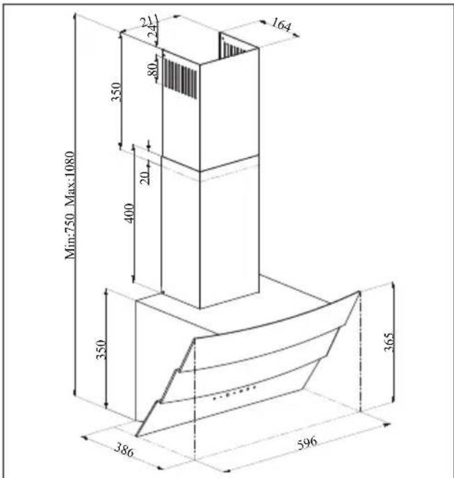
3.1 Installation accessories
natural_image
Simple line drawing of a rectangular metal bracket with two side slots (no text or symbols)1 x flue connection plate
natural_image
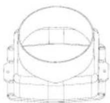
Technical line drawing of a mechanical component with concentric circles and mounting brackets (no text or symbols)1 x ∅150 mm plastic flue
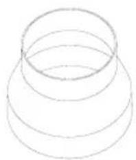
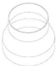
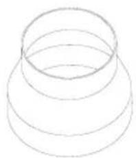
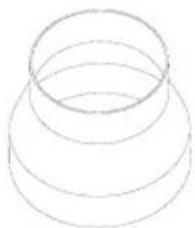
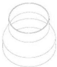
natural_image
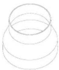
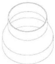
Simple line drawing of a three-tiered cylindrical structure (no text or symbols)1 x ∅120/150 mm plastic flue adapter
3 Installing your appliance
Information required for the preparation of the installation place for your hood is given below.
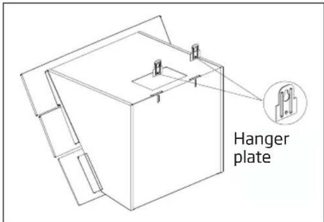
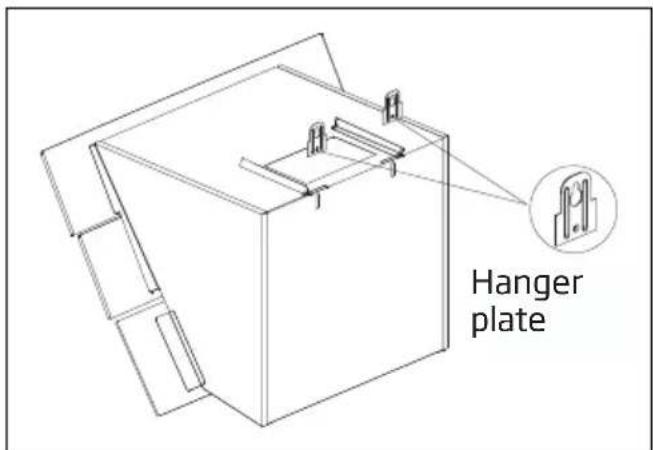
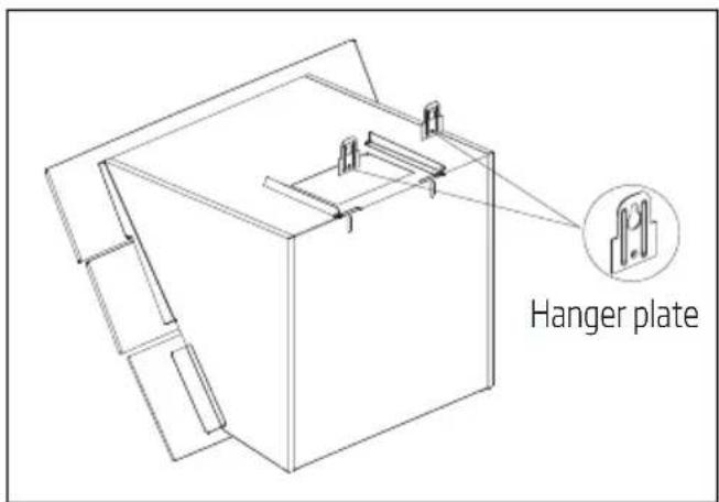
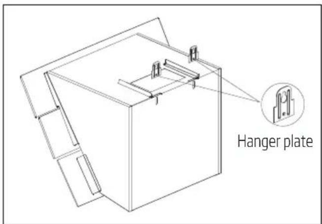
3.2 Installing the hood onto the wall
To install the hood onto the wall, loosen the screws of hanger plates on the motor housing and pull the plates upwards. Then, tighten the screws of the hanger plates. (Figure 3a).
(Figure 3a - 60)
(Figure 3a - 90)
(Figure 3b - 60)
(Figure 3b - 90)
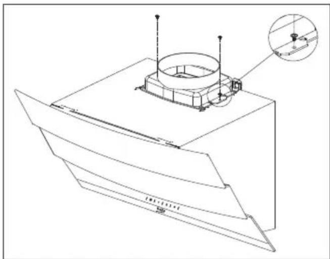
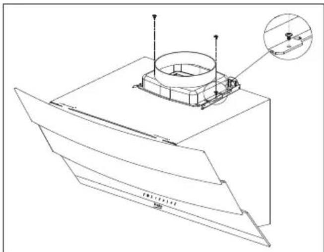
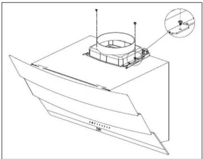
Secure the ∅150 mm plastic flue adapter onto the top of the body with 3.5x9.5 screw included in installation accessories (Figure 4).
If you will use ∅ 120 mm flue pipe, install ∅ 120 mm flue adapter onto it.
3 Installing your appliance
natural_image
Technical line drawing of a mechanical component with mounting bracket and cylindrical housing (no text or symbols)(Figure 4 - 60)

natural_image
Technical line drawing of a mechanical assembly with mounting brackets and a central cylindrical component (no text or symbols)(Figure 4 - 90)
3 Installing your appliance
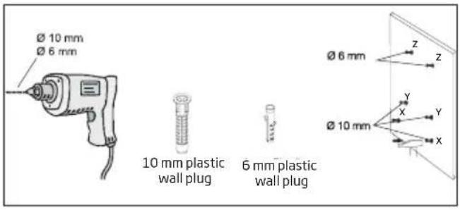
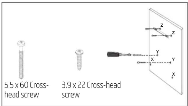
3.2.1 Boring the hanger holes
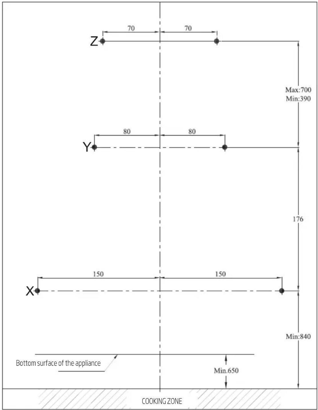
Affix the installation template onto the installation place of the hood. Drill the points market with (X,Y) (Figure 5) using a ∅ 10 mm bit and points market with (Z) (Figure 5) using a ∅ 6 mm bit.
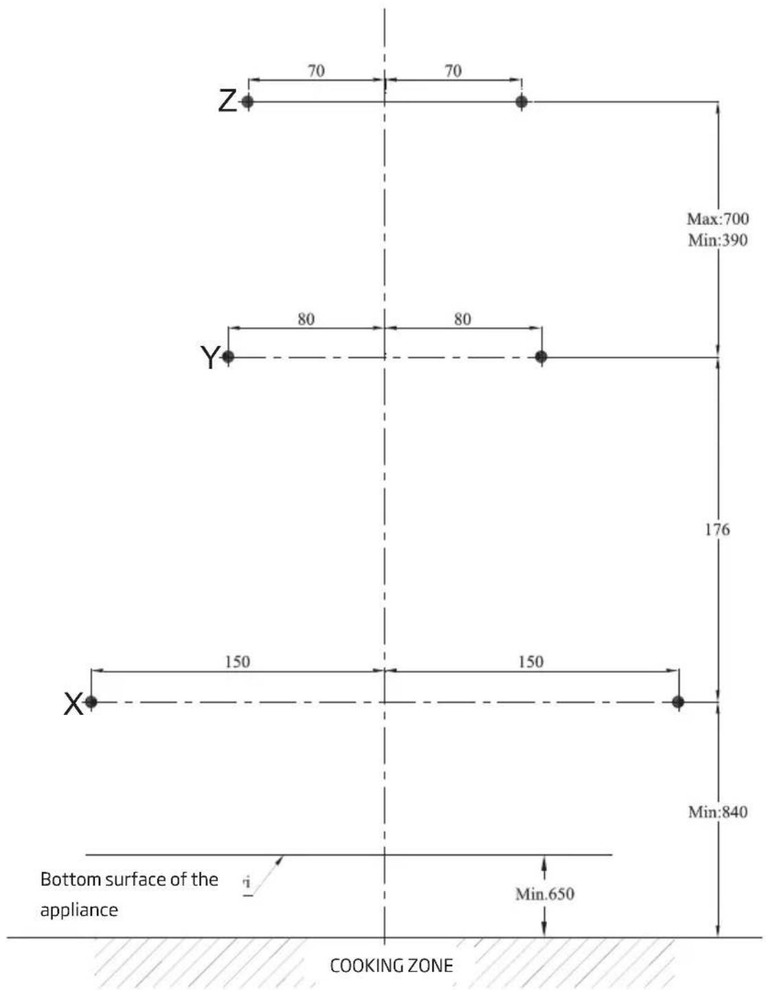
(Figure 5)
3 Installing your appliance
3.2.2 Hammering the wall plugs
Hammer ∅ 10 mm wall plugs (X,Y) into the holes drilled for hanger screws. Hammer 2 x ∅ 6 mm wall plugs (Z) into the holes drilled with a ∅6 mm bit for the external flue connection plate. (Figure 5)
3.2.3 Installing the hanger screws
Install 5.5x60 hanger screws into the ∅ 10 mm wall plugs (Y) you have hammered into the wall. There must be a gap of 5 mm between the screw head and the wall. (Figure 6)
Connect the internal flue connection plate to the 6 mm wall plugs (Z) on the wall using ∅ 3.9x22 screws. (Figure 6)
(Figure 6)
3.2.4 Hanging the hood onto the wall
- Hang the hood onto the screws you have installed into the Y holes.
- Open the side suction window of the hood by pulling it towards yourself. Install the 5.5x60 screws through the X holes located inside in order to secure the appliance.
3 Installing your appliance
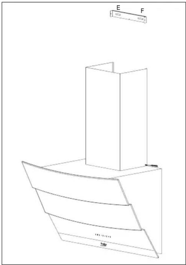
3.3 Installing the hood flue
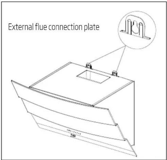
Disconnect the product from mains supply before starting flue installation. Fit the sheet metal flue parts around the body.
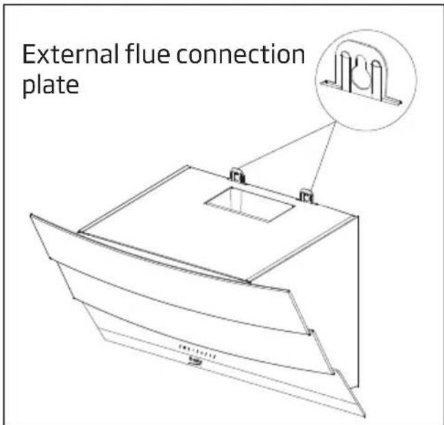
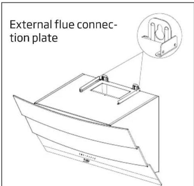
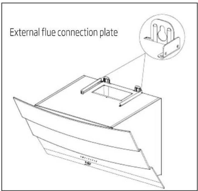
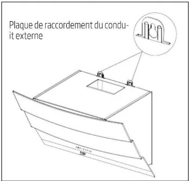
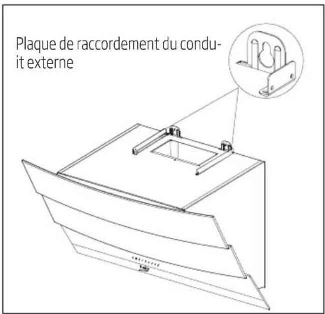
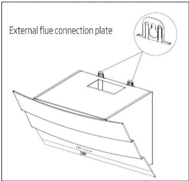
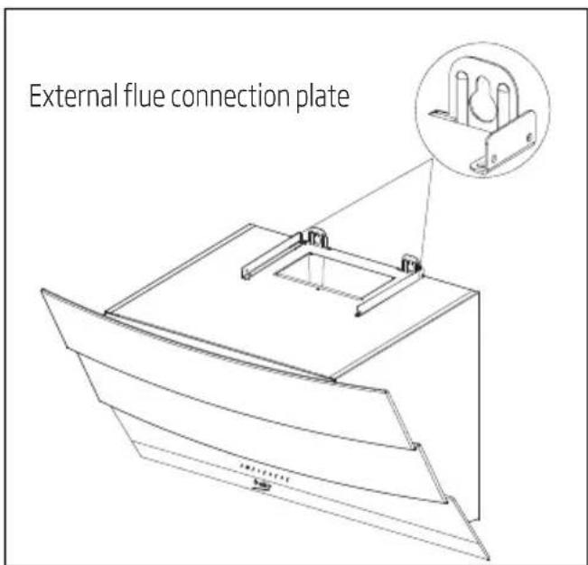
Screw the external flue to the external flue connection plates located on the motor housing. (Figure 3b / 7)
natural_image
Technical line drawing of a 3D architectural structure with labeled components E and F (no text or symbols beyond labels)(Figure 7)
Extend and screw the internal flue from its outer edges onto the flue connection plate which was secured to the wall (Figure 8).
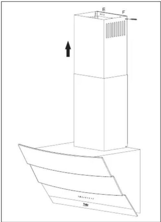
(Figure 8)
3 Installing your appliance
3.4.1 Using with flue connection
- The vapour is removed via flue pipe which is secured to the connection head on the hood.
- Diameter of the flue pipe should be equal to the diameter of connection ring. To allow the air be removed easily out of the room in horizontal arrangements, the pipe should be slightly tilted upwards (approximately 10°).
3.4.2 Using without flue connection
- Air is filtered by the carbon filter and returned to the room. Carbon filter is used when there is no flue in the house.
- if the hood will be used without flue connection remove the diverters inside the flue adapter.
- Remove the aluminum filter. To install the carbon filter, center the carbon filter on the plastic part on both sides of the fan body, and secure it on the tabs. Secure the filter by turning the tabs to right or left.
• Install the aluminum filter.
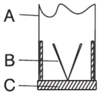
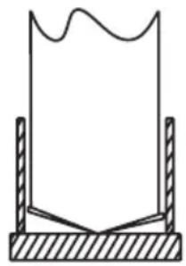
3.5 Flue connection:
Place adapter supplied together with the hood into the ventilation hole located on the top section of the hood. Procure a pipe with a diameter of 120/150 mm. Connect one end of the pipe to the adapter and the other end to the flue.
Make sure that these two connections are secure enough
so that they will not dislocate when the hood is operated in max. speed. Check that the flaps inside flue are functional when tightened with the clamp. Fit the flue connection pipe onto the adapter. If you fit the flue connection pipe inside the adapter, air suction will not occur since the flaps that prevent air backflow will remain closed.
It is not advisable to make connections to the flues connected with stoves or exhaust shafts. Do not make connections to such flues.
Pipe connection must be as short as possible and have minimum number of elbows.
A: Flue outlet pipe
B: Flaps that prevent backflow
C: Plastic flue
3.5.1 Backflow prevention system (N-RV)
When the hood is operated, flaps are closed in order to prevent possible odours and dust from entering into the ambient from outside.
Correct
natural_image
Simple line drawing of a container with wavy top and side supports (no text or symbols)Not correct
(Figure 9)
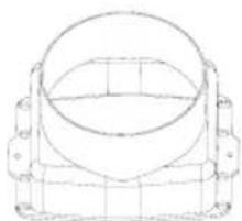
4 Operating your appliance

(Figure 9)
(A): Light On / Off key
(B): 1st level key
(C): 2nd level key
(D): 3rd level key
4.1 Digital electronic control with 3 levels
(A) Light On/Off Key: You can illuminate the cooking area by pressing this key.
(B) key: You can start your hood at speed level 1 by pressing this key.
When you press this key again to switch off the appliance, speed level indication on the display disappears.
(C) key: You can start your hood at speed level 2 by pressing this key.
When you press this key again to switch off the appliance, speed level indication on the display disappears.
(D) key: You can start your hood at speed level 3 by pressing this key.
When you press this key again to switch off the appliance, speed level indication on the display disappears.
Auto-stop in 15 min.:
This appliance is equipped with an Auto-Stop function which allows the appliance to ventilate the room for an additional period of time in order to remove the unpleasant odour and vapour in the room after the cooking is over. Appliance stops automatically after a certain period of time.
To enable the Auto-stop function, press any of the speed level keys (B, C, D) on the control for longer than 2 seconds. A timer with 15 minutes will be activated.
If you press the same speed level key while the Auto-stop function is enabled, function will be disabled and the appliance will stop.
If you select a different speed level this function will be disabled.
If you want your appliance to stop automatically, you must enable the Auto-stop function again.
Periodical cleaning of metal filters:
Filters must be cleaned at about every 60 hours of operation or 4 weeks depending on the frequency of usage.
4 Operating your appliance
4.2 Energy efficient usage:
- When operating the hood, adjust the speed level according to the odour and vapour intensity in order to prevent unnecessary power consumption.
- Use low speeds in normal conditions (1-2), and high speed (3) when smell and vapors are intensified.
- Lights on the hood are intended for illuminating the cooking zone.
Using them to illuminate the ambient/kitchen will result with unnecessary power consumption and inadequate illumination.
4.3 Operating the hood:
- Hood is equipped with a motor having various speed settings.
- For a better performance, we advise you to use low speeds in normal conditions, and high speeds when smell and vapors are intensified.
- You can start the hood by pressing the desired speed level key (B,C,D).
- You can illuminate the cooking area by pressing the light key. (A)
5 Cleaning and maintenance
Prior to cleaning and maintenance, unplug the appliance or turn the main switch off or loosen the fuse that supplies the hood.
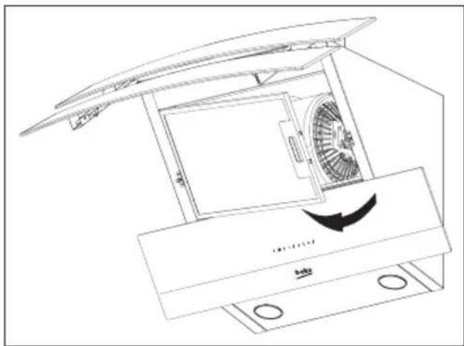
5.1 Aluminum filter
This filter captures oil particles in the air. You are recommended to clean your filter every month under normal usage conditions. First remove the aluminum filters for this process. Wash the filters with liquid detergent and rinse them with water and install them back after they get dry. Aluminum filters may get discolored as they are washed; this is normal and you don't need to change your filter.
5.1.1 Removing the aluminum filters
- Push the aluminum filter lock forward.
- Then, slightly lower it and pull forward. Otherwise, you may bend the filter. (Figure 10) After the aluminum filter is washed and dried, reinstall the filter to its slot by applying above steps in reverse order.
natural_image
Line drawing of a mechanical device with fan and housing, showing internal components and airflow direction (no text or symbols)(Figure 10)

You can also wash aluminum filters in dishwasher.
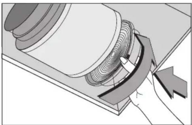
Carbon filter (Using without flue)
This filter removes the cooking odours. If it is not possible to use a flue, it purifies the air which is circulated inside the kitchen. Carbon filter of your appliance will get clogged in time depending on the frequency of use, style of cooking and regular cleaning of the aluminum filters.

Caution!
Carbon filter should never be washed.
You may obtain carbon filters from Beko Authorised Service Agents.
5.2.1 Replacing the carbon filter
- Remove the aluminum filters. (Figure 10)
- To remove carbon filter, turn the tabs counterclockwise and release the filter. (Figure 11)
• Install the new carbon filter.
• Install the aluminum filters.
natural_image
Diagram of a mechanical component with a hand operating a curved tool, showing internal gear teeth and motion (no text or symbols)(Figure 11)
Anti-odor filters contain charcoal (active carbon).
They must be changed with periods of approximately 6 months.
Regardless of using a carbon filter or not, aluminum filters must always be installed.
Do not operate your appliance without the aluminum filter in place. Using with carbon filter will decrease suction performance of the appliance.
5 Cleaning and maintenance
5.3 Cleaning
Particularly do not neglect to clean your hood immediately after you have made frying.
Use a soft cloth soaked with liquid detergent to clean the outer surface of your hood.
Never use abrasive or scratching materials for cleaning.
You may use the cleaning agents commercially available for persistent grease etc. by following the warnings on the product. In order not the scratch the brushed steel body, wipe in the same direction with the bush trace.
Do not use cleaning agents containing hydrochloric acid, bleach or abrasive powders in order to maintain the surface quality of your product. Use a cloth dampened in soapy water or special stainless steel cleaning spray for stainless steel steel surfaces. Remove the protective foil on the appliance.

Caution!
You may cause a fire if you do not follow the instructions on the cleaning and replacement of the filters of your hood.
If you need to transport the appliance:
- Keep the original packaging of the appliance. Transport the appliance with its original package, and follow the transport markings on the original package.
If you do not have the original package:
- Do not place any objects on the hood.
- Protect the outer surface from impacts.
- Pack the appliance so that it would not be damaged during transport.
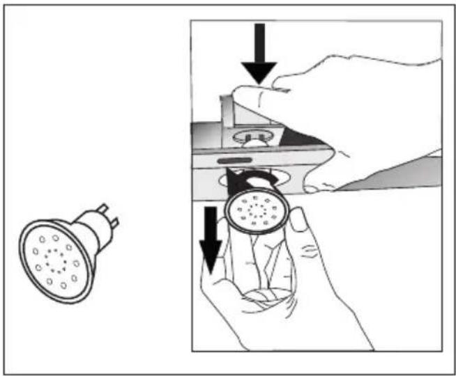
5.4 Replacing the lamps
Disconnect the hood from the mains supply.
This appliance is equipped with 3 W LED lamps.
To replace the LED lamps, press the lamp downwards from the rear section of the lamp holder to release the lamp. Then turn it counterclockwise by 1/4 tour and remove it.
Perform the above steps in reverse order to fit the new lamps.
natural_image
Illustration showing a showerhead being adjusted for a circular component, with arrows indicating the process (no text or symbols present)
You may procure lamps from Authorised Service Agents.
natural_image
Technical line drawing of a rectangular mechanical part with two recessed slots (no text or symbols)natural_image
Technical line drawing of a mechanical component with no visible text or symbolsnatural_image
Simple line drawing of a three-tiered cylindrical structure (no text or symbols)1 x Kunststoffabzugadapter (Ø 120/150 mm)
natural_image
Technical line drawing of a mechanical component with mounting bracket and cylindrical housing (no text or symbols)(Abbildung 4 - 60)

natural_image
Technical line drawing of a mechanical assembly with mounting brackets and a central cylindrical component (no text or symbols)(Abbildung 4 - 90)
natural_image
Technical line drawing of a cabinet or enclosure structure with labeled components E and F (no text or symbols beyond labels)(Abbildung 7)
(Abbildung 9)
natural_image
Technical line drawing of a mechanical device with fan and base components, no visible text or symbols(Abbildung 10)

natural_image
Diagram of a mechanical component with a curved arrow indicating motion or force, no text or symbols present(Abbildung 11)
natural_image
Illustration showing a showerhead being held by hands, with arrows indicating the process (no text or symbols present)
natural_image
Technical line drawing of a mechanical bracket or support plate (no text or symbols)natural_image
Technical line drawing of a mechanical component with concentric circles and mounting brackets (no text or symbols)1 x chimenea plástica de ∅150 mm
natural_image
Simple line drawing of a three-tiered cylindrical structure (no text or symbols)(Figura 3a - 60)
(Figura 3a - 90)
(Figura 3b - 60)
(Figura 3b - 90)
natural_image
Technical line drawing of a mechanical assembly with a central component and an inset detail (no text or symbols)(Figura 4 - 60)
natural_image
Technical line drawing of a mechanical assembly with mounting bracket and cylindrical component (no text or symbols)(Figura 4 - 90)
natural_image
Technical line drawing of a curved structural component with labeled parts E and F (no text or symbols beyond labels)(Figura 7)
(Figura 8)
(Figura 9)
natural_image
Technical line drawing of a mechanical device with fan and base components, no visible text or symbols(Figura 10)

natural_image
Diagram of a mechanical component with a hand operating a curved tool, showing internal layered structure (no text or symbols)(Figura 11)
natural_image
Illustration showing a showerhead being held by hands, with no text or symbols present.
natural_image
Technical line drawing of a mechanical bracket or support structure (no text or symbols)natural_image
Technical line drawing of a mechanical component with cylindrical and rectangular features (no text or symbols)natural_image
Simple line drawing of a three-tiered cylindrical structure (no text or symbols)(Figure 3a - 60)
(Figure 3a - 90)
(Figure 3b - 60)
(Figure 3b - 90)
natural_image
Technical line drawing of a mechanical assembly with a central component and an inset detail (no text or symbols)(Figure 4 - 60)

natural_image
Technical line drawing of a mechanical assembly with mounting brackets and a central cylindrical component (no text or symbols)(Figure 4 - 90)
natural_image
Technical line drawing of a 3D architectural structure with labeled components E and F (no text or symbols beyond labels)(Figure 7)
(Figure 9)
natural_image
Line drawing of a kitchen appliance with fan and door, showing internal structure and airflow direction (no text or symbols)(Figure 10)

natural_image
Diagram of a mechanical or electrical component with a hand operating a curved tool, showing internal layered structure (no text or symbols)(Figure 11)
natural_image
Illustration showing a showerhead being held by hands, with no text or symbols present.
natural_image
Technical line drawing of a rectangular mechanical part with two recessed slots (no text or symbols)natural_image
Technical line drawing of a mechanical component with mounting holes and a central cylindrical housing (no text or symbols)natural_image
Simple line drawing of a three-tiered cylindrical structure (no text or symbols)natural_image
Technical line drawing of a mechanical assembly with a central component and an inset detail (no text or symbols)(Rysunek 4 - 60)
natural_image
Technical line drawing of a mechanical assembly with mounting bracket and cylindrical component (no text or symbols)(Rysunek 4 - 90)
3 Montaż okapu
natural_image
Technical line drawing of a 3D architectural structure with labeled components E and F (no text or symbols beyond labels)(Rysunek 7)
(Rysunek 8)
3 Montaż okapu
natural_image
Simple line drawing of a container with wavy top and side supports (no text or symbols)(Rysunek 9)
natural_image
Technical line drawing of a mechanical device with fan and base components, showing internal airflow direction (no text or symbols)(Rysunek 10)

natural_image
Technical illustration of a mechanical assembly with a hand operating a curved component (no text or symbols visible)(Rysunek 11)

natural_image
Technical line drawing of a rectangular mechanical component with two recessed slots (no text or symbols)natural_image
Technical line drawing of a mechanical component with a circular housing and mounting brackets (no text or symbols)1 x ∅150 mm kunststof rookkanaal
natural_image
Simple line drawing of a three-tiered cylindrical object (no text or symbols)natural_image
Technical line drawing of a mechanical assembly with a central component and an inset detail (no text or symbols)(Afbeelding 4 - 60)

natural_image
Technical line drawing of a mechanical assembly with mounting brackets and a central cylindrical component (no text or symbols)(Afbeelding 4 - 90)
3 Uw apparaat installeren
natural_image
Technical line drawing of a 3D architectural structure with labeled components E and F (no text or symbols beyond labels)(Afbeelding 7)
(Afbeelding 8)
3 Uw apparaat installeren
(Afbeelding 9)
5.1 Aluminium filter
natural_image
Technical line drawing of a mechanical device with fan and base components, showing airflow direction (no text or symbols)(Afbeelding 10)

U kunt de aluminium filters ook in de vaatwasmachine wassen.
natural_image
Diagram of a mechanical or electrical component with a hand operating it, showing internal layered structure and directional arrows (no text or symbols)(Afbeelding 11)
natural_image
Illustration showing a showerhead being held by hands, with arrows indicating the process (no text or symbols present)
natural_image
Technical line drawing of a rectangular mechanical part with two recessed slots (no text or symbols)natural_image
Pure technical line drawing of a mechanical component with no text or symbols1 x ∅150 mm plastová trubice
natural_image
Simple line drawing of a three-tiered cylindrical object (no text or symbols)natural_image
Technical line drawing of a mechanical assembly with a central component and an inset detail (no text or symbols)(Obrázek 4 - 60)

natural_image
Technical line drawing of a mechanical assembly with mounting brackets and a central cylindrical component (no text or symbols)(Obrázek 4 - 90)
natural_image
Technical line drawing of a cabinet or enclosure structure with labeled components E and F (no text or symbols beyond labels)(Obrázek 7)
(Obrázek 8)
(Obrázek 9)
natural_image
Technical line drawing of a mechanical device with fan and base components, no visible text or symbols(Obrázek 10)

natural_image
Diagram of a mechanical or electrical component with a curved arrow indicating direction (no text or symbols present)(Obrázek 11)

natural_image
Line drawing of a rectangular electronic component with two slots (no text or symbols)natural_image
Technical line drawing of a mechanical component with cylindrical and rectangular parts (no text or symbols)natural_image
Simple line drawing of a three-tiered cylindrical object (no text or symbols)natural_image
Technical line drawing of a mechanical assembly with a central component and an inset detail (no text or symbols)(Figura 4 - 60)

natural_image
Technical line drawing of a mechanical assembly with mounting bracket and cylindrical component (no text or symbols)(Figura 4 - 90)
natural_image
Technical line drawing of a mechanical component with labeled sections E and F (no text or symbols on the diagram itself)(Figura 7)
(Figura 8)
(Figura 9
natural_image
Technical line drawing of a mechanical device with fan and base components, no visible text or symbols
natural_image
Diagram of a mechanical or electrical component with a hand operating a curved tool, showing internal layered structure (no text or symbols)(Figura 11)

natural_image
Technical line drawing of a rectangular mechanical part with two recessed slots (no text or symbols)natural_image
Pure technical line drawing of a mechanical component with no text or symbolsnatural_image
Simple line drawing of a three-tiered cylindrical structure (no text or symbols)(Slika 3a - 60)
(Slika 3b - 60)

(Slika 3a - 90)
(Slika 3b - 90)
natural_image
Technical line drawing of a mechanical assembly with a central component and an inset detail (no text or symbols)(Slika 4 - 60)

natural_image
Technical line drawing of a mechanical assembly with mounting bracket and cylindrical component (no text or symbols)(Slika 4 - 90)
(Slika 5)
(Slika 6)
3.2.4 Obesiti napo na steno
- Napo obesite na vijaka, ki ste ju namestili v luknji Y.
- Odprite stransko sesalno okno na napi tako, da ga potisnete proti sebi. Namestite vijaka 5.5x60 skozi odprtini X na notranji strani, tako da ju pri-trdite na napravo.
natural_image
Technical line drawing of a 3D architectural structure with labeled components E and F (no text or symbols beyond labels)(Slika 7)
natural_image
Technical line drawing of a multi-tiered industrial chimney with fan base and ventilation duct (no text or symbols)(Slika 8)
(Slika 9)
natural_image
Line drawing of a kitchen air conditioner unit with fan airflow direction (no text or symbols)(Slika 10)

natural_image
Diagram of a mechanical component with a curved arrow indicating motion or force, no visible text or symbols(Slika 11)
V filtrih, ki očistijo vonje, je oglje (aktivni ogljik).
natural_image
Illustration showing a showerhead being held by hands, with no text or symbols present.
Svetilke nabavite na pooblaščenem servisu.
natural_image
Line drawing of a rectangular electronic component with two slots (no text or symbols)natural_image
Technical line drawing of a mechanical component with a circular housing and mounting flanges (no text or symbols)natural_image
Simple line drawing of a three-tiered cylindrical structure (no text or symbols)natural_image
Technical line drawing of a mechanical assembly with a central component and an inset detail (no text or symbols)(obrázok 4 - 60)

natural_image
Technical line drawing of a mechanical assembly with mounting bracket and cylindrical component (no text or symbols)(obrázok 4 - 90)
natural_image
Technical line drawing of a curved structural component with labeled sections E and F (no text or symbols beyond labels)(obrázok 7)
natural_image
Technical line drawing of a multi-tiered industrial chimney with fan base and upward arrow indicator (no text or symbols)(obrázok 8)
natural_image
Technical line drawing of a mechanical device with fan and housing (no text or symbols)(obrázok 10)

natural_image
Diagram of a mechanical or electrical component with a hand operating a curved tool, showing internal layered structure (no text or symbols)(obrázok 11)
natural_image
Diagram of a mechanical device with a rotating component and a handle, showing no text or symbols.
natural_image
Technical line drawing of a rectangular mechanical part with two recessed slots (no text or symbols)natural_image
Pure technical line drawing of a mechanical component with no text or symbolsnatural_image
Simple line drawing of a three-tiered cylindrical object (no text or symbols)natural_image
Technical line drawing of a mechanical assembly with a central component and an inset detail (no text or symbols)(Рисунок 4 - 60)

natural_image
Technical line drawing of a mechanical assembly with a central component and an inset detail (no text or symbols)(Рисунок 4 - 90)
3 Установка приладу
natural_image
Technical line drawing of a 3D architectural structure with labeled components E and F (no text or symbols beyond labels)(Рисунок 7)
3 Установка приладу
(Рисунок 8)
(Рисунок 9)
natural_image
Technical line drawing of a mechanical device with fan and base components, no text or symbols present(Рисунок 10)

natural_image
Diagram of a mechanical or electrical component with a hand operating a curved tool (no text or symbols visible)(Рисунок 11)

natural_image
Technical line drawing of a rectangular mechanical component with two recessed slots (no text or symbols)natural_image
Technical line drawing of a mechanical component with mounting flanges (no text or symbols)natural_image
Simple line drawing of a three-tiered cylindrical object (no text or symbols)natural_image
Technical line drawing of a mechanical assembly with a central component and an inset detail (no text or symbols)(Рисунок 4 - 60)

natural_image
Technical line drawing of a mechanical assembly with a central component and an inset detail (no text or symbols)(Рисунок 4 - 90)
3 Установка прибора
natural_image
Technical line drawing of a curved structural component with labeled parts E and F (no text or symbols beyond labels)3 Установка прибора
(рисунок 8)
(рисунок 9)
natural_image
Technical line drawing of a mechanical device with fan and base components, no text or symbols presentРисунок 10

natural_image
Diagram of a mechanical component with a hand operating a curved tool, showing internal layered structure (no text or symbols)Рисунок 11
5 Чистка и уход
natural_image
Illustration of hands holding a circular component with arrows indicating direction (no text or symbols)
natural_image
Simple line drawing of a rectangular mechanical part with two side slots (no text or symbols)natural_image
Simple line drawing of a cylindrical object with a grid pattern, enclosed in a rectangular frame (no text or symbols)1 x evacuare din plastic Ø150 mm
natural_image
Simple line drawing of a three-tiered cylindrical object (no text or symbols)1 x adaptor evacuare din plastic ∅120/150 mm
natural_image
Technical line drawing of a mechanical assembly with a central component and an inset detail (no text or symbols)(Figura 4 - 60)

natural_image
Technical line drawing of a mechanical assembly with mounting bracket and cylindrical component (no text or symbols)(Figura 4 - 90)
natural_image
Technical line drawing of a 3D architectural structure with labeled components E and F (no text or symbols beyond labels)natural_image
Technical line drawing of a multi-tiered industrial chimney with fan base and ventilation duct (no text or symbols)(Figura 8)
3.4.1 Utilizarea cu racord de evacuare
natural_image
Simple line drawing of a container with wavy top and side supports (no text or symbols)Corect Incorrect
(Figura 9)
(Figura 9)
natural_image
Line drawing of a mechanical device with fan and base components, no text or symbols present(Figura 10)

natural_image
Diagram of a mechanical component with a hand operating a curved tool, showing internal gear teeth and motion (no text or symbols)(Figura 11)
natural_image
Illustration showing a hand holding a showerhead and a close-up of the device's handle, with no visible text or symbols.
natural_image
Simple line drawing of a rectangular metal bracket with two recessed slots (no text or symbols)1 x suitsutoruplaat
natural_image
Technical line drawing of a mechanical component with no visible text or symbols1 x plastsuitsutoru (läbimööduga 150 mm)
natural_image
Simple line drawing of a three-tiered cylindrical structure (no text or symbols)1 x plastsuitsutoru adapter (läbimööduga 120/150 mm)
3 Seadme paigaldamine
natural_image
Technical line drawing of a mechanical component with mounting bracket and cylindrical housing (no text or symbols)(Joonis 4 - 60)

natural_image
Technical line drawing of a mechanical assembly with mounting brackets and a central cylindrical component (no text or symbols)(Joonis 4 - 90)
3 Seadme paigaldamine
natural_image
Technical line drawing of a curved structural component with labeled sections E and F (no text or symbols beyond labels)(Joonis 7)
natural_image
Simple line drawing of a container with wavy top and side supports (no text or symbols)Vale
(Joonis 9)
4 Seadme kasutamine
(Joonis 9)
natural_image
Line drawing of a mechanical device with fan and housing, showing internal components and airflow direction (no text or symbols)(joonis 10)

natural_image
Diagram of a mechanical component with a hand operating a curved tool, showing internal gear teeth and motion (no text or symbols)(joonis 11)
natural_image
Illustration of hands holding a mechanical component with arrows indicating motion or force (no text or symbols)
natural_image
Simple line drawing of a rectangular metal bracket with two recessed slots (no text or symbols)natural_image
Technical line drawing of a mechanical component with no visible text or symbols1 x 150 mm skersmens plastikinis ortakis
natural_image
Simple line drawing of a three-tiered cylindrical structure (no text or symbols)1 x 120 / 150 mm skers- mens plastikinis ortakio adapteris
natural_image
Technical line drawing of a mechanical component with mounting bracket and cylindrical housing (no text or symbols)(4 pav.- 60)

natural_image
Technical line drawing of a mechanical assembly with mounting brackets and a central cylindrical component (no text or symbols)(4 pav.- 90)
natural_image
Technical line drawing of a 3D architectural structure with labeled components E and F (no text or symbols beyond labels)(7 pav.)
(9 pav.)
(A): Šviesos jjungimo / išjungimo mygtukas
(B): 1 lygio mygtukas
(C): 2 lygio mygtukas
(D): 3 lygio mygtukas
natural_image
Technical line drawing of a mechanical device with fan and base components, no visible text or symbols(10 pav.)

natural_image
Mechanical diagram showing a rotating component with a curved arrow indicating motion (no text or symbols)(11 pav.)
natural_image
Illustration showing a showerhead being adjusted to a circular component, with arrows indicating the process (no text or symbols present)
natural_image
Line drawing of a rectangular mechanical component with two mounting holes (no text or symbols)natural_image
Technical line drawing of a mechanical component with no visible text or symbolsPlastmasas gaisa izplūdes caurule, diamets 150 mm, 1 gab.

natural_image
Simple line drawing of a three-tiered cylindrical structure (no text or symbols)Plastmasas gaisa izplūdes caurules adapters, diamets 120/150 mm, 1 gab.
natural_image
Technical line drawing of a mechanical component with mounting bracket and cylindrical housing (no text or symbols)(4. attêls- 60)

natural_image
Technical line drawing of a mechanical assembly with mounting brackets and a central cylindrical component (no text or symbols)(4. attêls - 90)
natural_image
Technical line drawing of a mechanical component with labeled sections E and F (no text or symbols beyond labels)(7. attêls)
natural_image
Technical line drawing of a multi-tiered industrial chimney with fan base and ventilation duct (no text or symbols)(8. attēls)
(9. attêls)
natural_image
Technical line drawing of a mechanical device with fan and housing (no text or symbols)(10. attēls)

natural_image
Diagram of a mechanical or electrical component with a hand operating a curved tool, no visible text or symbols(11. attēls)
natural_image
Illustration showing a showerhead being adjusted to a circular component, with arrows indicating the process (no text or symbols present)
natural_image
Technical line drawing of a mechanical assembly with a central component and an inset detail (no text or symbols)(Figura 4 - 60)

natural_image
Technical line drawing of a mechanical assembly with mounting brackets and a central cylindrical component (no text or symbols)(Figura 4 - 90)
natural_image
Technical line drawing of a 3D architectural structure with labeled components E and F (no text or symbols beyond labels)(Figura 7)
natural_image
Technical line drawing of a multi-tiered industrial chimney with fan base and air duct (no text or symbols)(Figura 8)
natural_image
Simple line drawing of a container with wavy top and side supports (no text or symbols)(Figura 9)
(Figura 9)
natural_image
Technical line drawing of a mechanical device with fan and base components, no visible text or symbols(Figura 10)

natural_image
Diagram of a mechanical component with a hand operating a curved tool, showing internal layered structure (no text or symbols)(Figura 11)
natural_image
Illustration of hands holding a mechanical component with arrows indicating downward motion (no text or symbols)


- Please read this user manual first!
- Explanation of symbols
- CONTENTS
- 1
- Important instructions for safety and environment
- General safety
- Electrical safety
- Product safety
- Children's safety
- Intended use
- Compliance with WEEE regulation and disposal of the waste product
- Package information
- Technical specifications of your appliance
- Installing your appliance
- Caution!
- Installation accessories
- Installing the hood onto the wall
- Boring the hanger holes
- Hammering the wall plugs
- Installing the hanger screws
- Hanging the hood onto the wall
- Installing the hood flue
- Using with flue connection
- Using without flue connection
- Flue connection:
- Operating your appliance
- Digital electronic control with 3 levels
- Auto-stop in 15 min.:
- Periodical cleaning of metal filters:
- Energy efficient usage:
- Operating the hood:
- Cleaning and maintenance
- Aluminum filter
- Removing the aluminum filters
- Carbon filter (Using without flue)
- Replacing the carbon filter
- Cleaning
- If you do not have the original package:
- Replacing the lamps
- (Abbildung 11)
- Montaż okapu
- (Rysunek 11)
- Uw apparaat installeren
- Aluminium filter
- (Obrázek 11)
- (Slika 6)
- Obesiti napo na steno
- (Slika 11)
- (obrázok 11)
- Установка приладу
- Установка прибора
- Чистка и уход
- Utilizarea cu racord de evacuare
- Seadme paigaldamine
- Seadme kasutamine
- (joonis 11)
- (11. attēls)
Brand : BEKO
Model : HCA92641BH
Category : Range hood