PMPS 200 A1 - Welding machine PARKSIDE - Free user manual and instructions
Find the device manual for free PMPS 200 A1 PARKSIDE in PDF.

| Brand | Parkside |
| Model | PMPS 200 A1 |
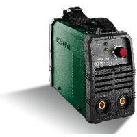
| Product Type | Multi-process welding machine with double pulse technology |
| Power Supply | 230 V~ 50 Hz, 16 A (fuse) |
| Weight | Approx. 17 kg |
| MIG/MAG Welding Current | 50–160 A (standard MIG), 30–160 A (pulsed MIG) |
| MMA Welding Current | 20–140 A |
| TIG Welding Current | 20–200 A |
| Open Circuit Voltage | 60 V |
| Welding Processes | MAG, pulsed MIG, double pulse MIG, MMA, TIG (Lift TIG) |
| Usable Wire Diameters | Steel: 0.8 / 1.0 mm; Flux-cored wire: 0.6 / 0.8 / 0.9 / 1.0 mm; Aluminium: 1.0 / 1.2 mm; CuSi: 0.8 mm; Stainless steel: 0.8 / 1.0 mm |
| Max. Wire Spool | 5–15 kg (depending on spool diameter) |
| Protection Rating | IP21S |
| Safety Protections | Auto-reset thermostat, Anti Stick, VRD (voltage reduction device), overtemperature protection |
| Included Equipment | MIG torch with cable, 2 m ground cable with clamp, 2 m MMA electrode holder with cable, 4 torch tips (0.6/0.8/0.9/1.0 mm), aluminium nozzle, slag hammer, welding liners for aluminium and steel, instruction manual |
| Maintenance | Regular cleaning with compressed air, cloth or brush; maintenance by a qualified electrician |
| Warranty | Commercial warranty (see conditions) + legal conformity warranty (2 years) |
| Certifications | CE, compliant with directives 2014/30/EU, 2014/35/EU, 2011/65/EU |
| EMC Class | Class A (industrial use) |
| Operating Temperature | Output measured at 20 °C ambient |
Frequently Asked Questions - PMPS 200 A1 PARKSIDE
User questions about PMPS 200 A1 PARKSIDE
0 question about this device. Answer the ones you know or ask your own.
Ask a new question about this device
Download the instructions for your Welding machine in PDF format for free! Find your manual PMPS 200 A1 - PARKSIDE and take your electronic device back in hand. On this page are published all the documents necessary for the use of your device. PMPS 200 A1 by PARKSIDE.
USER MANUAL PMPS 200 A1 PARKSIDE
text_image
PDF ONLINE www.1idl-service.com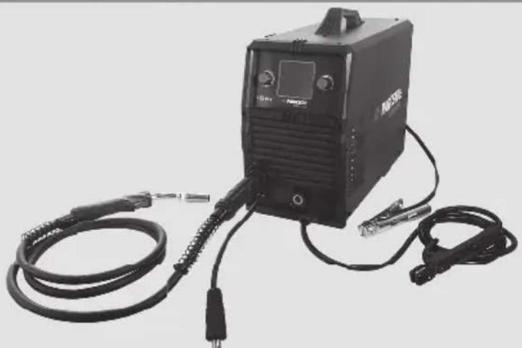
natural_image
Exterior view of a black industrial welding torch with attached cables and connectors (no visible text or symbols)MULTI-WELDER WITH DOUBLE PULSE TECHNOLOGY PMPS 200 A1 MULTISCHWEISSGERÄT MIT DÖPPELPULS-TECHNOLOGIE PMPS 200 A1 POSTE À SOUDER MULTIPROCEDÉS AVEC TECHNOLOGIE DOUBLE PULSÉE PMPS 200 A1
GB IE NI CY MT
MULTI-WELDER WITH DOUBLE PULSE TECHNOLOGY
Operation and Safety Notes
Translation of the original instructions
FR BE CH
POSTE À SOUDER MULTIPROCÉDÉS AVEC TECHNOLOGIE DOUBLE PULSÉE
Before reading, unfold the page containing the illustrations and familiarise yourself with all functions of the device.
DE AT CH
GB/IE/NI/CY/MT Operation and Safety Notes Page 5
natural_image
Close-up of mechanical components with no visible text or symbols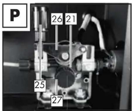
text_image
P 26 21 25 27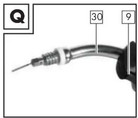
text_image
Q 30 9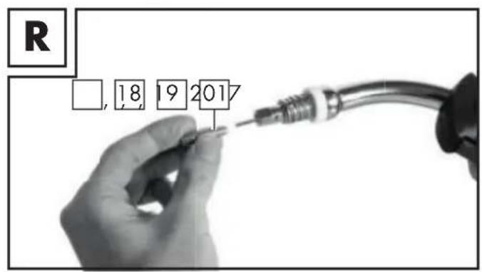
text_image
R □, 18 19 2017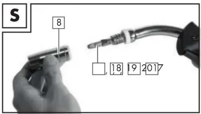
text_image
S 8 □, 18 19 2017Table of pictograms used....Page 5
Introduction Page 6
Intended use Page 6
Package contents......Page 7
Parts description....Page 8
Technical Specifications....Page 8
Safety instructions Page 10
Before using the device....Page 18
Selecting the welding method....Page 18
Assembly for welding with wire electrodes....Page 18
Replacing the welding core....Page 19
Adaptation of device to solid welding wire with inert gas....Page 19
Adaptation of device to flux-cored welding wire without inert gas....Page 20
Inserting welding wire....Page 20
Welding with wire electrodes....Page 21
Switching the device on and off....Page 21
MAG welding Page 22
PMIG welding....Page 22
DPMIG welding....Page 23
Creating a weld seam....Page 24
MMA welding......Page 26
TIG welding Page 28
Maintenance and cleaning....Page 29
Information about recycling and disposal......Page 29
EC Declaration of Conformity....Page 30
Warranty and service information......Page 31
Warranty conditions....Page 31
Warranty period and statutory claims for defects....Page 31
Extent of warranty....Page 31
Processing of warranty claims ......Page 31
Service......Page 32
| Table of pictograms used | |||
| Attention!Read the operating instructions! | I_2 | Rated value of the welding current | |
| Mains input; number of phases and alternating current symbol and rated value of the frequency. | I_1 eff | Effective value of the greatest mains power | |
| U_0 | Rated value of the no-load voltage | ||
| Do not dispose of any electrical devices in domestic waste! | U_1 | Rated value of the mains voltage | |
| Never use the device in the open air or when it's raining! | U_2 | Standardised operating voltage | |
 | Electric shock from the welding electrode can be fatal!Inhalation of welding fumes can endanger your health. | I_1 max  | Greatest rated value of the mains powerCaution! Risk of electric shock! |
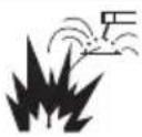 | Welding sparks can cause an explosion or fire. |  | Important note! |
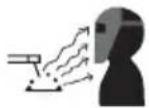 | Arc beams can damage your eyes and injure your skin. |  | Dispose of the device and packaging in an environmentally friendly manner! |
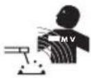 | Electromagnetic fields can disrupt the function of cardiac pacemakers. |  | Risk of serious injury or death. |
 | Attention: Potential hazards! |  | Protection type |
 | Earth terminal | 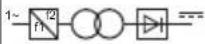 | Single-phase static frequency converter-transformer-commutator |
| H | Insulation class |  | Direct current |
 | Made from recycled material. |  | Greatest rated value of the welding time in intermittent mode _ON^t |
 | Greatest rated value of the welding time in continuous mode t_ON(max) |  | Manual arc welding with encased rod electrodes |
 | Metal inert and active gas welding including the use of flux-cored wire |  | Tungsten inert gas welding |
Multi-Welder with Double Pulse Technology PMPS 200 A1
- Introduction
Congratulations! You have purchased one of our high-quality devices. Please familiarise yourself with the product before using it for the first time. To do so, please read through the following operating and safety instructions carefully. This tool must be set up or used only
by people who have been trained to do so.
KEEP OUT OF THE REACH OF CHILDREN!
- Intended use
The device is designed for welding with solid wire (MIG and MAG), MMA welding (welding with rod electrodes), TIG welding (tungsten inert gas welding) as well as welding with flux-cored wire.
When using solid wires which do not contain inert gas in solid form, then you must use inert gas in addition. When using self-shielding flux-cored wire, you do not need to use any additional gas. In this case, the inert gas is contained in the welding wire in powdered form and is therefore channelled straight into the arc. This means that the device is not susceptible to wind when working outdoors. Only suitable wire electrodes may be used for the device. This welding device is designed for manual arc welding (MMA welding) of steel, stainless steel, steel sheet and cast materials, using the appropriate coated electrodes. Refer to the information from the electrode manufacturer. Only suitable electrodes may be used for the device. For tungsten inert gas welding (TIG welding) it is essential that you observe the operating and safety instructions for the TIG torch you are using, in addition to the instructions and safety instructions in these operating instructions. If it is not handled properly the product can be dangerous for individuals, animals and property. Use the product only as described and only for the specific applications as stated. Keep these instructions in a safe place. Ensure you hand over all documentation when passing the product on to anyone else. Any use that differs to the intended use as stated above is prohibited and potentially dangerous. Damage or injury caused by misuse or disregarding the above warning is not covered by the warranty or any liability on the part of the manufacturer. Commercial use will void the warranty. Observing the safety instructions and assembly instructions and operating information in the instructions for use is also a component of the intended use. It is imperative to adhere to the applicable accident prevention regulations. The device must not be used:
■ in insufficiently ventilated rooms,
■ in explosive environments,
■ to defrost pipes,
■ in the vicinity of people with cardiac pacemakers and
■ in close proximity to easily flammable materials.
Residual risk
Even if you operate the device as intended, there will be residual risks. The following dangers may occur in connection with the build and design of this MIG pulse welder:
■ Eye injuries caused by glare, touching hot parts of the device or workpiece (burn injury),
In case of improper protection, risk of accident and fire through sparks and slag particles,
- Harmful emissions from smoke and gases if there is a lack of air or if closed rooms are insufficiently extracted.

PLEASE NOTE: Reduce the residual risk by carefully using the device as intended and observing all instructions.
- Package contents
1 Multi-Welder with Double Pulse Technology 200 A1
1 MIG welding torch with 2 m welding cable
1 high-quality, galvanised copper earth terminal, A-shape with 2 m cable
1 electrode holder MMA with 2 m welding cable
4 contact tips for steel/flux-cored wire (1x 0.6 mm; 1x 0.8 mm; 1x 0.9 mm; 1x 1.0 mm)
Labelling in accordance with the diameter: 0.6; 0.8; 0.9; 1.0
1 aluminium nozzle (1x 1.0 mm pre-fitted)
1 chipping hammer
1 welding core for aluminium wire (pre-fitted)
1 welding core for steel/stainless steel and flux-cored wire
1 set of operating instructions
- Parts description
| 1 | Cover of the wire feed unit | 20 | Welding nozzle (1.0 mm) |
| 2 | Handle | 21 | Feed roll |
| 3 | Mains plug | 22 | Chipping hammer |
| 4 | Earthing cable with earth terminal | 23 | Main switch ON/OFF(incl. power indicator lamp) |
| 5 | MMA electrode holder | 24 | Gas connection |
| 6 | Plug, polarisation cable assembly | 25 | Setting screw |
| 7 | Cable assembly with direct connection(Euro central connector) | 26 | Thrust roller unit |
| 7a | Fixing ring | 27 | Feed roll holder |
| 8 | Torch nozzle | 28 | Fixing for welding wire spool |
| 9 | Torch button | 29 | Wire outlet |
| 10 | Torch | 30 | Torch neck |
| 11 | Torch hose | 31 | Small tubes |
| 12 | Rotary switch for settingthe welding voltage | 32 | Welding wire spool(not part of the scope of delivery) |
| 13 | Rotary switch for settingthe welding current | 33 | Bracket for welding wire spool |
| 14 | Display | 34 | Locking nuts |
| 15 | Welding core for aluminium wire | 35 | Adapter for welding wire spool |
| 16 | Cable assembly bracket | 36 | Welding core for steel/stainless steeland flux-cored wire |
| 17 | Welding nozzle (0.6 mm) | ||
| 18 | Welding nozzle (0.8 mm) | ||
| 19 | Welding nozzle (0.9 mm) | ||
• Technical Specifications
| Max. rated input power: 6 kVA | |
| Mains connection: 230 V~ 50 Hz | |
| Weight: approx. 17 kg | |
| Fuse: 16 A |
Wire welding:
| Welding current: MIG 50–160 A; Pulse MIG 30–160 A | |||||
| No-load voltage: U | _o : 60 V | ||||
| Greatest rated value of the mains power: I | _1max : 24 A | ||||
| Effective value of the greatest mains power: I | _1eff : 11.2 A | ||||
| Welding wire reel max.: approx. 5–15 kg | |||||
| Characteristic value Flat | |||||
| Welding wire specifications: Type of welding, type of wire and diameter | |||||
| MIG | Steel wire: 0.8 / 1.0 mm | ||||
| Flux-cored wire: 0.6/ 0.8 / 0.9 / 1.0 mm | |||||
| Pulse MIG / double pulse MIG | Steel wire/Stainless steel wire: 0.8 / 1.0 mm | ||||
| CuSi: 0.8 mm | |||||
| AlSi/AlMg: 1.0 / 1.2 mm | |||||
| Aluminium: 1.0 / 1.2 mm | |||||
| Suitable wire rolls | |||||
| External diameter | Internal diam-eter | Width | Weight with AlSi / AlMg / Al wire | Weight with steel/ stainless steel/ CuSi and flux-cored wire | With adapter 35 |
| 300 mm 52 | mm 102 mm ≤ 7 | kg ≤ 15 kg | No | ||
| 200 mm | 52 mm | 53 mm | ≤ 2 kg | ≤ 5 kg | Yes |
MMA welding:
| Welding current: 20–140 A | |
| No-load voltage: U | _o : 60 V |
| Greatest rated value of the mains power: I | _1max : 23.5 A |
| Effective value of the greatest mains power: I | _1eff : 11 A |
| Characteristic value: | Falling |
| Suitable electrodes: | 1.6 mm / 2.0 mm / 2.5 mm / 3.2 mm |
TIG welding:
| Welding current: | 20–200 A |
| No-load voltage: | U_0 : 60 V |
| Greatest rated value of the mains power: | I_1max : 26 A |
| Effective value of the greatest mains power: | I_1eff : 12.2 A |
| Characteristic value: | Falling |
PLEASE NOTE: Changes to technical and visual aspects of the product may be made as part of future developments without notice. Accordingly, no warranty is offered for the physical dimensions, information and specifications in these operating instructions. The operating instructions cannot therefore be used as the basis for asserting a legal claim.
PLEASE NOTE: The use of the term 'device' in the following text refers to the multi-welder with double pulse technology described in this instruction manual.
- Safety instructions
⚠️ Please read the operating instructions with care and observe the notes described. Familiarise yourself with the device, its proper use and the safety instructions using these operating instructions. The rating plate contains all technical data of this welder; please learn about the technical features of this device.
WARNING! - Keep the packaging material away from small children. There is a risk of suffocation!
- Repairs or/and maintenance work must only be carried out by qualified electricians. - This device may be used by children aged 16 years and older, and by persons with reduced physical, sensory or mental capacities, or a lack of experience and knowledge, if they are supervised or have been instructed in how to use the device safely and understand the dangers that may arise when using it. Do not allow children to play with the device. Cleaning and day-to-day maintenance must not be performed by children without supervision.
■ Repairs or/and maintenance work must only be carried out by qualified electricians.
■ Only use the welding cables provided in the scope of delivery.
■ During operation, the device should not be positioned directly against the wall, should not be covered or jammed between other devices so that sufficient air can always be absorbed through the ventilation slats. Make sure that the device is correctly connected to the mains voltage. Avoid any form of tensile stress of the power cable. Disconnect the mains plug from the socket prior to setting up the device in another location.
If the device is not in operation, always switch it off by pressing the ON/OFF switch. Place the electrode holder on an insulated surface and only remove the electrodes from the holder after allowing it to cool down for 15 minutes.
■ Pay attention to the condition of the welding cable, electrode holder and the earth terminals. Wear and tear of the insulation
and the live parts can lead to hazards and reduce the quality of the welding work.
■ Arc welding creates sparks, molten metal parts and smoke. Therefore ensure that: All flammable substances and/or materials are removed from the work station and its immediate surrounding.
■ Ensure the work station is ventilated.
- Do not weld on containers, vessels or tubes that contain or contained flammable liquids or gases.
A warning of direct contact with the
welding current circuit. The no-load voltage between the electrode holder and earth terminal can be dangerous, there is a risk of electric shock.
- Do not store the device in a damp or wet environment or in the rain. Protection rating IP21S is applicable in this case.
- Protect your eyes using the appropriate protective glasses (DIN level 9–10), or an automatic welding helmet (in accordance with EN 166, 175 and 389; protection levels DIN 9–13). Wear gloves and dry protective clothing that are free of oil and grease to protect the skin from exposure to ultraviolet radiation of the arc.
WARNING! We use the welding power source to defrost pipes.
Please note:
■ The light radiation emitted by the arc can damage eyes and cause burns to the skin.
- Arc welding creates sparks and drops of melted metal. The welded workpiece starts to glow and remains hot for a relatively long period of time. Therefore, do not touch the workpiece with bare hands.
- Arc welding can cause vapours to be released that may be hazardous to health. Be careful not to inhale these vapours.
■ Protect yourself from the harmful effects of the arc and keep people that are not involved in the work away from the arc, maintaining a distance of at least 2 m.
! ATTENTION!
■ During the operation of the welder, other consumers may experience problems with the voltage supply depending on the network conditions at the connection point. In case of doubt, please contact your energy supply company.
■ During the operation of the welder, other devices may malfunction, e.g. hearing aids, cardiac pacemakers, etc.
- Potential hazards during electric arc welding
There are a series of potential hazards that can occur during electric arc welding. It is therefore particularly important for the welder to observe the following rules to avoid endangering him/herself and others and to prevent damage to people and the device.
■ Work on the mains voltage side, e.g. on cables, plugs, sockets etc., may only be carried out by qualified electricians according to national and local regulations.
■ Work on the mains voltage side, e.g. on cables, plugs, sockets etc., may only be carried out by qualified electricians according to national and local regulations.
In the event of accidents, disconnect the welder from the mains voltage immediately.
If electrical contact voltages occur, switch off the device immediately and have it checked by a qualified electrician.
■ Always ensure good electrical contacts on the welding current side.
■ Always wear insulating gloves on both hands during welding work. These provide protection from electrical shocks (no-load voltage of the welding current circuit), harmful radiations (heat and UV radiation) and incandescent metal and splashes of slag.
■ Wear sturdy, insulating shoes. The shoes should also insulate when exposed to moisture. Loafers are not suitable as falling incandescent metal droplets can cause burns.
■ Wear suitable protective clothing, no synthetic garments.
- Do not look into the arc without eye protection; only use a welding mask with the prescribed protective glass as per DIN. In addition to light and heat radiation, which can dazzle or cause burns, the arc also emits UV radiation. Without suitable protection the invisible ultraviolet radiation can cause very painful conjunctivitis which is not apparent until several hours later. Furthermore, UV radiation can cause burns with sunburn-like effects on unprotected parts of the body.
■ Any persons in the vicinity of the electric arc or helpers must also be informed of the dangers and be equipped with the necessary protective equipment. If necessary, set up protective walls.
■ Ensure an adequate supply of fresh air whilst welding, particularly in small spaces, as welding produces smoke and harmful gases.
■ No welding work may be carried out on containers that have been used
- for storing gases, fuels, mineral oils or similar – even if they have been
- empty for a long time – as possible residues may present a risk of explosion.
■ Special regulations apply in rooms where there is a risk of fire or explosion.
■ Welded joints that are subject to heavy stress loads and are required to comply with certain safety requirements may only be carried out by specially trained and certified welders. Examples of this are pressure vessels, running rails, tow bars, etc.
■ ⚠️ ATTENTION! Always connect the earth terminal as close as possible to the point of weld to provide the shortest possible path for the welding current from the electrode to the earth terminal. Never connect the earth terminal to the housing of the welder! Never connect the earth terminal to earthed parts far away from the workpiece, e.g. a water pipe in another corner of the room. This could otherwise damage the protective bonding system of the room you are welding.
■ Do not use the welder in the rain.
- Do not use the welder in a moist environment.
■ Only place the welder on a level surface.
■ The output is rated at an ambient temperature of 20 °C .
The welding time may be reduced at higher temperatures.
RISK OF ELECTRIC SHOCK:
Electric shock from a welding electrode can be fatal. Do not weld in rain or snow. Wear dry insulating gloves. Do not touch the electrodes with bare hands. Do not wear wet or damaged gloves. Protect yourself from electric shock with insulation against the workpiece. Do not open the device housing.
DANGER FROM WELDING FUMES:
■ Inhalation of welding fumes can endanger health. Do not keep your head in the fumes. Use the equipment in open areas. Use extractors to remove the fumes.
DANGER FROM WELDING SPARKS:
■ Welding sparks can cause an explosion or fire. Keep flammable substances away from the welding location. Do not weld near flammable materials. Welding sparks can cause fires. Keep a fire extinguisher close by and an observer should be present to be able to use it immediately. Do not weld on drums or any other closed containers.
DANGER FROM ARC BEAMS:
- Arc beams can damage your eyes and injure your skin. Wear a hat and safety goggles. Wear hearing protection and high, closed shirt collars. Wear welding safety helmets and make sure you use the appropriate filter settings. Wear complete body protection.
DANGER FROM ELECTROMAGNETIC FIELDS:
■ Welding current generates electromagnetic fields. Do not use if you have a medical implant. Never wrap the welding cable around your body. Guide welding cables together.
- Welding mask-specific safety instructions
- With the help of a bright light source (e.g. lighter) always check the proper functioning of the welding mask prior to starting with any welding work.
■ Weld spatters can damage the protective screen. Immediately replace damaged or scratched protective screens.
- Immediately replace damaged or highly contaminated or splattered components.
■ The device must only be operated by people aged 16 or over.
■ Please familiarise yourself with the welding safety instructions. Also refer to the safety instructions of your welder.
■ Always wear a welding mask while welding. If you do not do this, you could sustain severe lesions to the retina.
■ Always wear protective clothing during welding operations.
■ Never use a welding mask without the welding lens. There is a risk of damage to the eyes!
■ Regularly replace the protective screen to ensure good visibility and fatigue-proof work.
- Environment with increased electrical hazard
When welding in environments with increased electrical hazard, the following safety instructions must be observed. Environments with increased electrical hazard may be encountered, for example:
- In workplaces where the space for movement is restricted, such that the welder is working in a forced posture (e.g.: kneeling, sitting, lying) and is touching electrically conductive parts; - In workplaces which are restricted completely or in part in terms of electrical conductivity and where there is a high risk through avoidable or accidental touching by the welder;
In wet, humid or hot workplaces where the air humidity or sweat significantly reduces the resistance of human skin and the insulating properties or effect of protective equipment.
■ Even a metal conductor or scaffolding can create an environment with increased electrical hazard.
In this type of environment, insulated mats and pads must be used. Furthermore gauntlet gloves and head protection made of leather or other insulating materials must be worn to insulate the body against Earth. The welding power source must be located outside the working area or electrically conductive surfaces and out of the welder's reach. Additional protection against a shock from the mains power in the event of a fault can be provided by using a fault-circuit interrupter, which is operated with a leakage current of no more than 30 mA and covers all mains-powered devices in close proximity. The fault-circuit interrupter must be suitable for all types of current.
There must be means of rapid electrical isolation of the welding power source or the welding circuit (e.g. emergency stop device) which are easily accessible. When using welders under electrically dangerous conditions, the output voltage of the welder must not be greater than 113 volt when idling (peak value). Based on the output voltage this welder may be used in these conditions.
• Welding in tight spaces
■ When welding in tight spaces this may pose a hazard through toxic gases (risk of suffocation).
In tight spaces you may only weld if there are trained individuals in the immediate vicinity who can intervene if necessary. In this case, before starting the welding procedure, an expert must carry out an assessment in order to determine what steps are necessary, in order to guarantee safety at work and which precautionary measures should be taken during the actual welding procedure.
• Total of no-load voltages
- When more than one welding power source is operated at the same time, their no-load voltages may add up and lead to an increased electrical hazard. Welding power sources must be connected in such a way that the danger is minimised. The individual welding power sources, with their individual control units and connections, must be clearly marked, in order to be able to identify which device belongs to which welding power circuit.
- Protective clothing
■ At work, the welder must protect his/her whole body by using appropriate clothing and face protection against radiations and burns. The following steps must be observed:
- Wear protective clothing prior to welding work
- Wear gloves.
- Open windows or use fans to guarantee air supply.
- Wear safety goggles and face mask.
■ Gauntlet gloves made of a suitable material (leather) must be worn on both hands. They must be in perfect condition.
■ A suitable apron must be worn to protect clothing from flying sparks and burns. When specific work, e.g. overhead welding, is required, a protective suit must be worn and, if necessary, even head protection.
PROTECTION AGAINST RAYS AND BURNS
- Warn of the danger to the eyes by hanging up a sign saying "Caution! Do not look into flames!" in the work area. The workplaces must be shielded so that the persons in the vicinity are protected. Unauthorised persons must be kept away from welding work.
■ The walls in the immediate vicinity of fixed workplaces should neither be bright coloured or shiny. Windows up to head height must be protected to prevent rays from penetrating or reflecting through them, e.g. by using suitable paint.
• EMC Device Classification
According to the standard IEC 60974-10, this is a welder in electromagnetic compatibility Class A. Class A devices are devices that are suitable for use in all other areas except living areas and areas that are directly connected to a low-voltage supply mains that (also) supplies residential buildings. Class A devices must adhere to the Class A limit values.
WARNING NOTICE: Class A devices are intended for use in an industrial environment. Due to the power-related as well as the radiated interference variables, difficulties might arise in ensuring electromagnetic compatibility in other environments.
Even if the device complies with the emission limit values in accordance with the standard, such devices can still cause electromagnetic interference in sensitive systems and devices. The user is responsible for
faults caused by the arc while working, and the user must take suitable protective measures. In doing so, the user must consider the following:
- power cables, control, signal and telecommunication lines
- computer and other microprocessor controlled devices
- television, radio and other playback devices
- electronic and electrical safety equipment
- persons with cardiac pacemakers or hearing aids
– measurement and calibration devices
– noise immunity of other devices in the vicinity
– the time of day at which the work is being done.
The following is recommended to reduce possible interference radiation:
- fit a mains filter to the mains connection
– service the device regularly and keep it in good condition - welding cables should be completely unwound and installed parallel on the floor, if possible
- if possible, devices and systems at risk from interference radiation should be removed from the work area or shielded.
PLEASE NOTE:
This device complies with IEC 61000-3-12, provided that the Ssc short circuit power is larger or equal to 5692.5 kW at the interface point between the operator's supply and the public supply. It is the responsibility of the installer or user of the device, after consultation with the distribution system operator if necessary, to make sure that the device is only connected to a supply with an Ssc short circuit power which is larger or equal to 5692.5 kW.
! PLEASE NOTE:
Determine (if necessary in consultation with the power supplier) the maximum permitted Zmax system impedance at the interface point of the user supply.
The device must only be connected to a user supply with a Zmax system impedance of 0.242 Ω or less.
• Overload protection
The welder is protected against overheating by means of an automatic protection device (thermostat with automatic restart). The protective device breaks the electrical circuit if overheating occurs. In the case of overheating, the words: "over heating" will be shown on the display.
Allow the device to cool down for the activation of the protection device. After approx. 15 minutes, the device is ready to be used again.
- Before using the device
Take all parts from the packaging and check whether the MIG pulse welder or parts show any damage. If this is the case, do not use the MIG pulse welder. Contact the manufacturer via the indicated service address.
■ Remove all protective films and other transport packaging.
- Check that the delivery is complete.
- Selecting the welding method
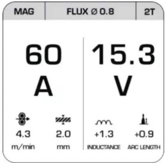
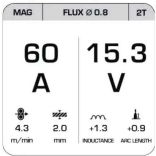
PLEASE NOTE: All the values shown in the following drawings are solely examples and do not represent any recommendations for specific welding parameters.
Drawing 1 Drawing 2
text_image
MAG FLUX Ø 0.8 2T 60 A 15.3 V 4.3 2.0 m +1.3 +0.9 m/min mm INDUCTANCE ARC LENGTH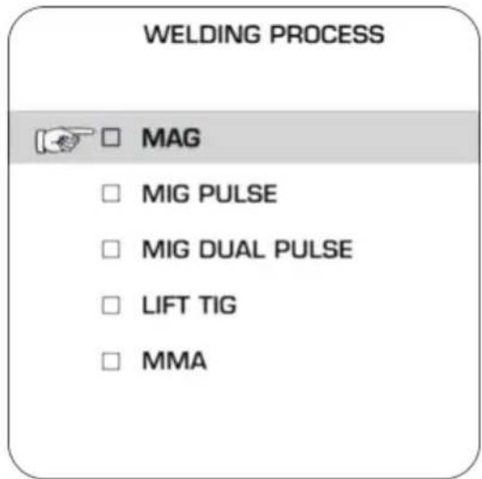
text_image
WELDING PROCESS MAG MIG PULSE MIG DUAL PULSE LIFT TIG MMAWhen you switch the device on, the last used welding method is automatically enabled. The other parameters (current, voltage, etc.) will also be loaded as previously set. To change the welding method, first press the rotary switch for setting the welding current 13 (hereafter called switch 13). Select the upper left field by rotating the switch 13. The currently selected welding method is displayed here [MAG in drawing 1]. Then press the switch 13 again.
The menu for selecting the welding mode will open [see drawing 2]. Rotate the switch 13, to select the required welding method. Confirm your selection by pressing the switch 13 again. Now press the rotary switch for setting the welding voltage 12, to select the appropriate welding method.
- Assembly for welding with wire electrodes
ATTENTION: Prevent the risk of an electric shock, injury or damage. To do this always unplug the mains plug from the socket prior to each maintenance task or preparatory work.
PLEASE NOTE: Different welding wires will be needed depending on the application. Feed roll, contact tip and wire cross-section must be compatible with one another. The device is suitable for wire rolls weighing up to maximum 15 kg.
- Replacing the welding core
The pre-installed welding core 15 is designed for aluminium wire. The welding core 36 which is not pre-installed is suitable for steel and stainless steel as well as for flux-cored wire. Undo the locking nuts 34 , by rotating them anti-clockwise. Then pull the welding core 15 out of the cable assembly with direct connection 7 and now guide the new welding core with the narrow end first, into the cable assembly with direct connection 7 . Push the complete new welding core through and then fix it with the locking nuts 34 .
When connecting the torch with the core 36 (not pre-installed), first push the small tube 31 into the (lower) opening provided for this purpose on the Euro central connector of the welder. In this way the liquid pumping of the wire will be guaranteed.
● Adaptation of device to solid welding wire with inert gas
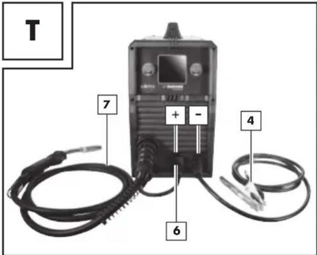
The correct connections for solid wire welding when using inert gas are shown in Fig. S.
text_image
T 7 + - 6 4First connect the plug with the connector marked with the "+" (see Fig. T). To fix it in place, rotate in a clockwise direction. If you are in any doubt, then please contact a professional.
■ Connect the cable assembly with direct connect into the appropriate connector (see Fig. T). To fix the connection, tighten the fixing ring in a clockwise direction.
■ Then connect the earth cable with the corresponding connector, marked with the "-" (see Fig. T). To fix the connection in place, rotate in a clockwise direction.
■ Pull the protective cap off the gas connection on the back of the device.
Now connect the inert gas feed including the pressure reducer (not included with the delivery) to the gas connection ^24 (see Fig. C). Inert gas is required if you are not using flux-cored wire with integrated solid inert gas. If necessary, observe the notes for your pressure reducer (not included with the delivery). You can use the following formula as a guideline for adjusting the gas flow:
Wire diameter in mm x 10 = gas flow in l/min
For example, using 0.8 mm wire, will give a value of approx. 8 l/min.
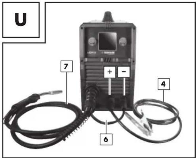
- Adaptation of device to flux-cored welding wire without inert gas
If you are using flux-cored welding wire with integrated inert gas, then you do not have to have an external inert gas supply.
text_image
U 7 + - 6 4First connect the plug with the connector marked with the "-" (see Fig. U). To fix it in place, rotate in a clockwise direction. If you are in any doubt, then please contact a professional.
■ Connect the cable assembly with direct connection into the appropriate connector. To fix the connection, tighten the connection in a clockwise direction.
Then connect the earth cable with the corresponding connector, marked with the "+" (see Fig. U) and to fix the connection in place, rotate in a clockwise direction.
- Inserting welding wire
■ Unlock and open the cover of the wire feed unit by pushing the release knob upwards.
■ Unlock the roller unit by turning the fixing for the welding spot anti-clockwise (see Fig. G).
Pull the fixing of the welding spool off the bracket of the welding wire spool 33 (see Fig. G).
PLEASE NOTE: Make sure that the end of the wire does not come loose and cause the roll to roll out on its own. The end of the wire may not be released until during assembly.
■ Completely unpack the welding wire sp33, so that it can unrolled without difficulty. Do not release the wire end yet.
If the wire roll is approx. 10 cm wide, remove the adapter: For wire rolls with a width of approx. 5 cm, the adapter 35 remains in position.
Place the wire roll on the bracket of the welding wire sp33. Make sure that the roll unwinds on the side of the 29 wire feed guide and that the end of the welding wire is below the welding spool (see Fig. M and N).
Place the fixing of the welding spot back on and lock it by pressing and turning it clockwise.
■ Undo the adjustment screw and swing it downwards (see Fig. I).
■ Turn the thrust roller unit to the side (see Fig. J).
■ Loosen the feed roll holder by turning it anti-clockwise and pull it forwards and off (see Fig. K).
On the top of the feed 23 check whether the appropriate wire thickness is indicated. If necessary, the feed roll 21 has to be turned over or replaced. The welding wire must be positioned in the upper groove!
■ Erect the feed roll holder again and screw clockwise direction.
■ Remove the torch nozzle by pulling and turning it clockwise (see Fig. L).
■ Unscrew the relevant welding nozzle, 18, 19 or 20 (see Fig. L).
- Guide the cable assembly with direct connection away from the welding device as straight as possible (place it on the floor).
Take the wire end out of the edge of the spool.
- Trim the wire end with wire scissors or a diagonal cutter in order to remove the damaged, bent ends of the wire (see Fig. M).

PLEASE NOTE: The welding wire must be kept under tension the entire time in order to avoid a casing and a roll out! Therefore it is recommended to carry out the work with an additional person.
■ Push the welding wire through the wire feed guide (see Fig. N).
■ Guide the welding wire along the feed 21 and push it into the wire feed 29.
■ Swivel the thrust roller unit towards the feed roll 21 (see Fig. P).
■ Mount the adjustmentscrew (see Fig. P).
Set the counter pressure with the adjustment screw. The welding wire must be firmly positioned between the thrust roller and feed roll [21] in the upper guide without being crushed (see Fig. O).
■ Switch on the welding device on the main switch (see Fig. C).
■ Press the torch button Make sure that your inert gas cylinder is kept firmly closed, until the welding wire has reached the required position.
Now the wire feed system pushes the welding wire through the cable assembly and the torch 10.
As soon as 1–2 cm of the welding wire protrudes from the torch neck release the torch button again (see Fig. Q).
■ Switch off the welder at the main switch.
Screw the relevant welding nozzle, 17, 18, 19 or 20 back on (see Fig. R). Make sure that the contact tip 17, 18, 19 or 20 matches the diameter of the welding wire used. With the welding wire delivered with the product, the contact tip 17, 18, 19 or 20 with the labelling 1.0 or 1.0 A must be used when using solid aluminium wire.
Connect the torch nozzle back onto the torch neck 30 with a turn to the right (see Fig. S).

WARNING!
Always unplug the mains plug from the socket prior to each maintenance
task or preparatory work in order to prevent the risk of an electric shock, injury or damage.
• Welding with wire electrodes
- Switching the device on and off
Switch the welder on and off on the main switch ^23 . If you do not intend to use the welder for an extended period, remove the mains plug from the power socket. This is the only way to completely de-energise the device.

PLEASE NOTE: All the values shown in the following drawings are solely examples and do not present any recommendations for specific welding parameters.
- MAG welding
Drawing 3 Drawing 4
text_image
MAG FLUX Ø 0.8 2T 60 A 15.3 V 4.3 2.0 m +1.3 +0.9 m/min mm INDUCTANCE ARC LENGTH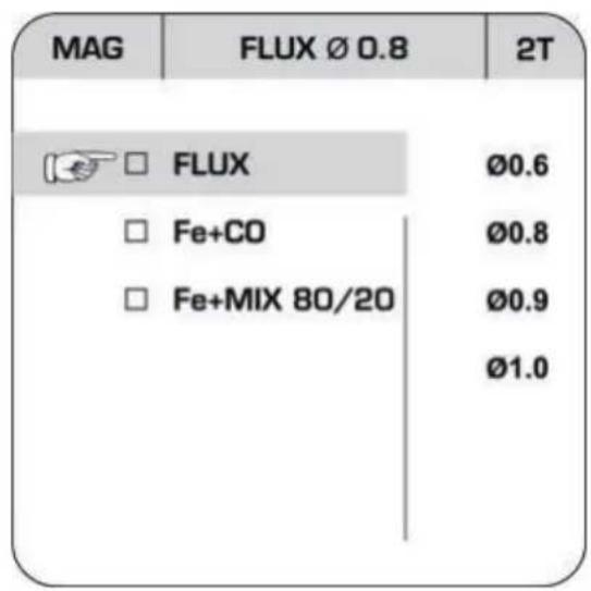
text_image
MAG FLUX Ø 0.8 2T FLUX Ø0.6 Fe+CO Ø0.8 Fe+MIX 80/20 Ø0.9 Ø1.0When selecting the MAG method you can choose between flux-cored wire and steel wire.
First press the rotary switch for setting the welding current ^13 (hereafter called switch ^13 ).
Select the upper middle field by rotating the switch 13 . The currently selected wire will be shown here [FLUX 0.8 in drawing 3]. Then press the switch 13 again, to go to the wire selection menu [drawing 4]. By rotating and pressing the switch 13 you can set the welding wire you are using as well as the inert gas used, if necessary. For steel wire (Fe + CO / Fe + MIX 80/20) you can use CO 2 or a 80% Argon / 20% CO 2 mix as the inert gas. Then by rotating and pressing the switch 13 you can set the wire diameter. By pressing the switch for voltage setting 12 (hereafter called switch 12 ) you can go back to the welding settings. In the top bar you can now choose between "2T" (2-touch) and "4T" (4-touch) accordingly. With 2-touch welding the voltage is present as long as the trigger on the torch is pressed. With the 4-touch method the voltage is present once the trigger of the torch is pressed briefly and then released. The voltage will be interrupted as soon as the trigger is pressed again.
You can now set the welding current by rotating the switch ^13 . The wire feed adjusts automatically and axrecommendation is displayed for the material thickness to be welded, in mm.
Rotate the switch 12 to adjust the voltage which also changes the length of the arc "ARC LENGTH". If the switch 12 is pressed and then rotated, then you can adjust the inductance "INDUCTANCE".
- PMIG welding
Drawing 5
other
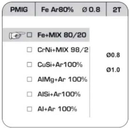
| Sample | Value (%) | | :--- | :--- | | Fe+MIX 80/20 | | | CrNi+MIX 98/2 | Ø0.8 | | CuSi+Ar100% | Ø1.0 | | AlMg+Ar 100% | | | AlSi+Ar100% | | | Al+Ar 100% | |For reduced spatter and a more stable arc, you can select the Pulse MIG method. With this method you can choose between steel wire, CrNi, CuSi, AlMg, AlSi and Al wire [drawing 5]. In addition, the inert gas required will be specified.
When using particular wires, use the following inert gases:
Fe (steel wire): [80% Argon/20% CO2]
CrNi (stainless steel) wire: [98% Argon/2% CO2]
CuSi, AlMg, AlSi and aluminium wire: [100% Argon]
Navigation within the PMIG menu is carried out in a similar way to navigation in the "MAG" menu using the switches 12 and 13. The diameter of the welding wire used can also be set and you can select "2T" and "4T".
• DPMIG welding
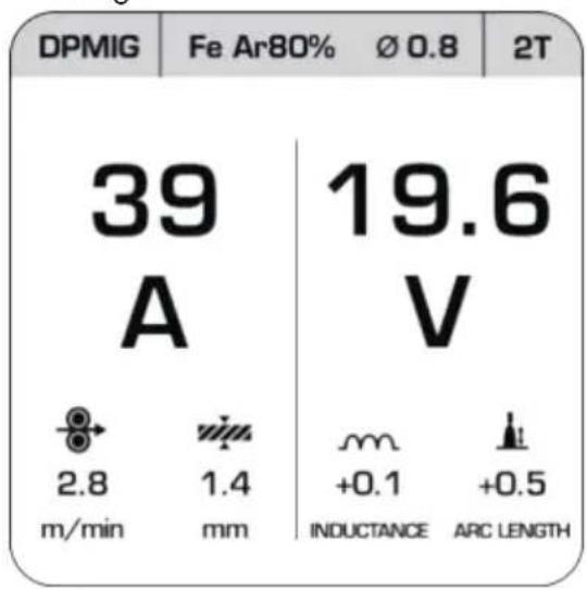
Using the double pulse MIG method, less heat is transferred into the material. Because of this, this method is particularly suitable for welding thin sheets of stainless steel and aluminium.
With this method the same wire electrodes and inert gases can be used as with PMIG welding.
Navigation within the DPMIG menu is carried out in a similar way to navigation in the "MAG" menu using the switches 12 and 13. The diameter of the welding wire used can also be set and you can select "2T" and "4T".
In addition, after setting the welding wire used, this is where you can recall the parameter diagram by pressing the switch 13 twice. This is where you can set the individual parameters for the DPMIG method. We recommend that you use the pre-set values at this point. As an advanced user, you can adjust the individual values to adapt the welding procedure precisely to your planned work. To reset the parameters which have been set, return to the DPMIG [drawing 6] and keep the switch 12 pressed for approx. 5 seconds.
Drawing 6
text_image
DPMIG Fe Ar80% Ø 0.8 2T 39 19.6 A V 2.8 1.4 m + m/ min mm +0.1 +0.5 INDUCTANCE ARC LENGTHWARNING! RISK OF BURNS!
Welded workpieces are very hot and can cause burns. Always use pliers to move hot, welded workpieces.
Please proceed as follows once you have electrically connected the welder:
- Put on appropriate protective clothing in accordance with the specifications and prepare your workplace.
Connect the earthing cable to the workpiece that is to be welded using the earth terminal. Please ensure good electrical conductivity.
The area to be welded on the workpiece must be free of rust and paint.
- Set the required welding parameters depending on the welding method selected.
-
Guide the torch nozzle to the position on the workpiece that is to be welded.
■ Press the torch button, in order to feed the welding wire. Once the electric arc is burning, the device feeds welding wire into the weld pool. -
You can work out the ideal settings for the welding current by carrying out trial welds on a test piece. A properly set electric arc has a mild, uniform buzzing sound.
In case of a rough or hard rattle, switch to a higher power level (increase welding current).
If the welding lens is big enough, the torch is slowly guided along the desired edge. The distance between the torch nozzle 8 and workpiece should be as small as possible (it must not be greater than 10 mm).
If necessary, oscillate a little to increase the size of the weld pool. For inexperienced welders, it is often difficult initially to create a decent electric arc. To do so, the welding current must be set correctly.
The penetration depth (corresponds to the depth of the welding seam in the material) should be as deep as possible without allowing the welding pool to fall through the workpiece.
If the welding current is too low, the welding wire will not melt properly. Consequently, the welding wire repeatedly dips in the welding pool as far as the workpiece.
The slag can only be removed from the seam once it has cooled down. To continue welding an interrupted seam:
■ First remove the slag at the starting point.
The arc is ignited in the weld groove, guided to the connection point, melted properly and finally the weld seam is continued.

CAUTION: Please note that the torch must always be placed on an insulated surface after
welding.
■ Always switch off the welder after completing welding work and during breaks and pull the mains plug from the power socket.
- Creating a weld seam
Forehand welding
Push the torch forwards. Result: The penetration depth is lower, broader weld width, flatter weld bead (visible surface of the seam) and greater fusion error tolerance.
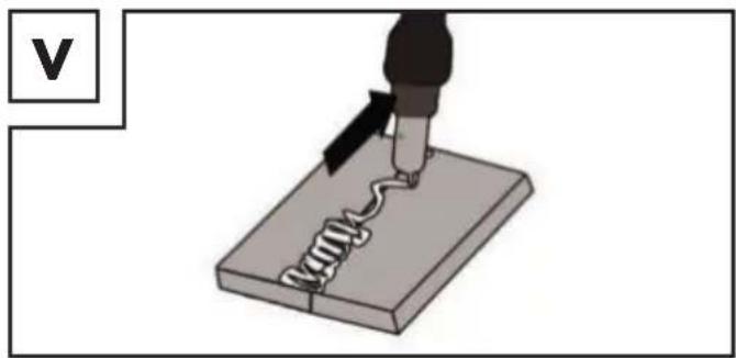
Backhand welding
The torch is dragged from the weld seam (Fig. V). Result: Greater penetration depth, narrower weld width, higher weld bead and lower fusion error tolerance.
Welded joints
There are two-basic types of joints in welding: Butt welds (outer edge) and angle welding (inner edge and overlapping).
Butt welds
With butt welds of up to 2 mm material thickness, the weld edges are completely brought together. For greater thicknesses, a gap of 0.5–4 mm must be selected. The ideal gap depends on the welded material (aluminium or steel), the material composition as well as the type of welding selected. This gap should be determined by welding on a sample workpiece.
Flat butt welds
Welds should be made without interruption and with a sufficient penetration depth. Therefore, it is extremely important to be well prepared. The quality of the weld result is affected by: the amperage, the gap between weld edges, the inclination of the torch and the diameter of the welding wire. The steeper you hold the torch against the workpiece, the higher the penetration depth and vice versa.
natural_image
Illustration of a soldering iron being inserted into a circuit board (no text or symbols)To forestall or reduce deformations that can happen during the material hardening process, it is good to fix the workpiece with a device. Avoid stiffening the welded structure to prevent cracks in the weld. These problems can be avoided if there is a possibility of turning the workpiece so that the weld can be carried out in two passes running in opposite directions.
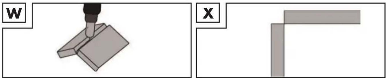
Welds on the outer edge
The preparation for this is very simple (Fig. W, X).
natural_image
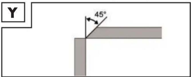
Two technical diagrams showing a tool interacting with a mechanical component and a separate view of a rectangular block (no text or symbols present)However, it is no longer expedient for thicker materials. In this case, it is better to prepare a joint as shown below, in which the edge of the plate is angled (Fig. Y).
text_image
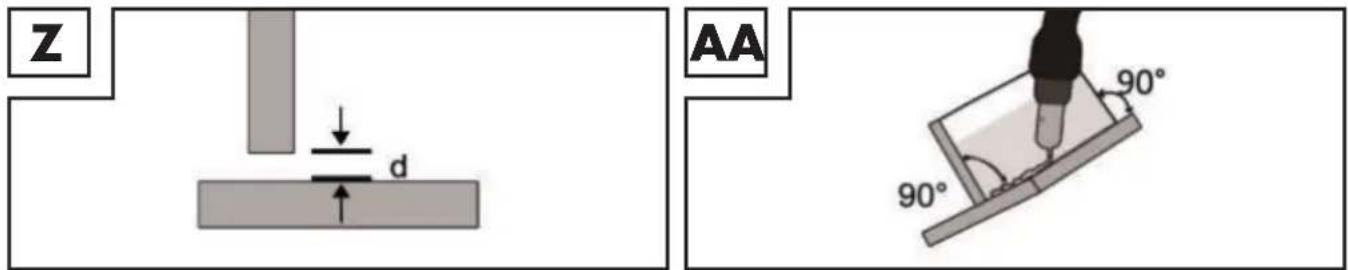
Y 45°Fillet weld connections
A fillet weld is created if the workpieces are perpendicular to each other. The weld should be shaped like a triangle with sides of equal length and a slight fillet (Fig. Z, AA).
Welds on an inner edge
The preparation for this weld joint is very simple and is carried out for thicknesses of 5 mm. The dimension "d" needs to be reduced to a minimum and should always be less than 2 mm (Fig. Z).
text_image
Z AA 90° 90°However, it is no longer expedient for thicker materials. In this case, it is better to prepare a joint as shown in Figure Y, in which the edge of the plate is angled.
Overlap welds
The most common preparation is that with straight weld edges. The weld can be released using a standard angle weld seam. Both workpieces must be brought as close to each other as possible, as shown in Fig. AB.
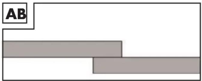
text_image
AB- MMA welding
■ Make sure that the main switch is set to position "O" ("OFF") or that the mains plug 3 is not plugged into the socket.
■ Connect the electrode holder and the earth terminal 4 to the welding device, as shown in Fig. AC. Also refer to the information from the electrode manufacturer and make sure that the polarity can be changed depending on the type of electrodes used, if necessary.
- Put on appropriate protective clothing in accordance with the specifications and prepare your workplace.
■ Connect the earth terminal to the workpiece.
- Clamp the electrode into the electrode holder
- Switch the device on by setting the main switch to the "I" ("ON") position.
Select the "MMA" mode as described under "Selecting the welding method".
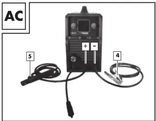
text_image
AC 5 + - 4PLEASE NOTE: All the values shown in the following drawings are solely examples and do not represent any recommendations for specific welding parameters.
Drawing 7
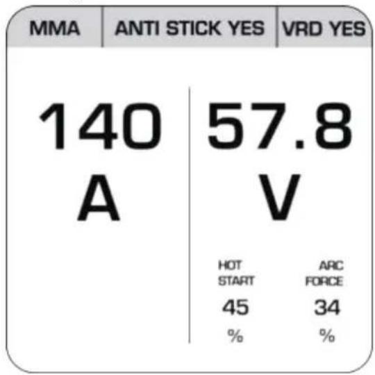
text_image
MMA ANTI STICK YES VRD YES 140 57.8 A V HOT ARC START FORCE 45 34 % %When selecting the MMA method you can adjust the welding current by turning the rotary switch for setting the welding current 13 (hereafter called switch 13 ). In addition the ANTI STICK and VRD functions can be activated by pressing and rotating the switch 13 . [drawing 7] ANTI STICK prevents the electrodes from sticking to the workpiece. Using VRD reduces the voltage if you are not going to weld straightaway. This results in a particularly safe way of working. By rotating or pressing and then rotating the switch for setting the voltage 12 you can adjust the values for HOT START and ARC FORCE. Increasing the HOT START value will make it easier to ignite the arc. ARC FORCE works in a similar way to ANTI STICK by stopping the electrodes from sticking to the workpiece.

PLEASE NOTE: Guideline values for the welding current to be used, depending on the electrode meter can be taken from the following table.
| ∅ Electrode Welding current | |
| 1.6 mm 40-60 A | |
| 2.0 mm 60-80 A | |
| 2.5 mm 80-100 A | |
| 3.2 mm 100-140A |

ATTENTION: Do not bring the earth terminal 4 and the electrode holder 5/electrodes into direct act with one another.

ATTENTION: When welding with rod electrodes, the electrode holder ^5 and the earth terminal must be connected in accordance with the information from the electrode manufacturer.
- Put on appropriate protective clothing in accordance with the specifications and prepare your workplace.
To stop the procedure, set the main switch ON/O ^23 to "O" ("OFF") position.

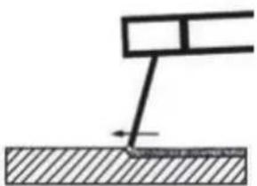
ATTENTION: Do not dab on the workpiece with the electrode. It could be damaged and make it more difficult to ignite the arc. As the soon as the arc is ignited, try to maintain a distance to the workpiece which corresponds to the diameter of the electrode being used. The gap should remain as constant as possible while you are welding. The inclination of the electrode in the direction of operation should be 20–30 degrees.
ATTENTION: Always use pliers to remove used electrodes or hot workpieces. Make sure that the electrode holder is always placed onto an insulated surface after welding. The slag can only be removed from the seam once it has cooled down. To continue welding an interrupted seam:
■ First remove the slag at the connection point.
The electric arc is ignited in the weld groove, guided to the connection point, melted properly there and then continues from that point.
ATTENTION: Welding generates heat. Therefore the welding device must run idle for at least half an hour after use. Alternatively, you can leave the device to cool for an hour. The device can only be packed away and stored once the temperature of the device is normal again.
ATTENTION: A voltage which is 10% below the rated input voltage of the welder can have the following consequences:
■ The power to the device will reduce.
■ The arc stops or becomes unstable.
ATTENTION:
■ The arc radiation can lead to inflammation of the eyes and skin burns.
■ Casting and welding slag can cause eye injuries and burns.
It is essential that you only use the welding cable which is included with the delivery. Choose between push and drag welding. The following section shows the impact of the direction of movement on the properties of the weld seam:
| Push welding Drag welding | ||
 |  | |
| Burn smaller larger | ||
| Weld seam width larger smaller | ||
| Weld bead flatter higher | ||
| Weld seam fault larger smaller |
PLEASE NOTE: You decide for yourself which type of welding is most suitable, once you have welded a sample piece.
PLEASE NOTE: Once it has worn down completely, the electrode must be replaced.
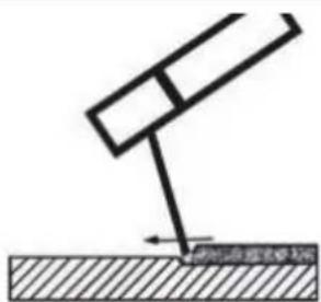
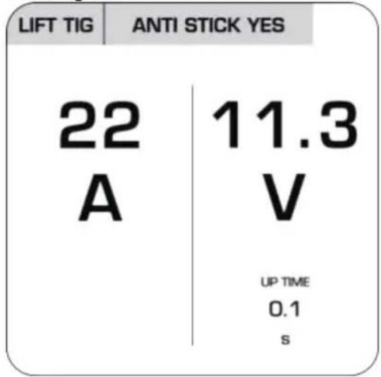
• TIG welding
For TIG welding please follow the instructions for your TIG torch. TIG mode can be activated as described under "Selecting the welding method".
PLEASE NOTE: All the values shown in the following drawings are solely examples and do not represent any recommendations for specific welding parameters.
Drawing 8
text_image
LIFT TIG ANTI STICK YES 22 11.3 A V UP TIME 0.1 sWhen selecting the TIG method you can adjust the welding current by turning the rotary switch for setting the welding current 13 (hereafter called switch 13). In addition the ANTI STICK function can be activated by pressing and rotating the switch 13. [drawing 8] ANTI STICK prevents the electrodes from sticking to the workpiece. By rotating the switch for setting the voltage 12 you can adjust the value for UP TIME. This determines how quickly the power will ramp up when you start the welding work. A higher value means a slower power up.
- Maintenance and cleaning
PLEASE NOTE: The welding device must be regularly serviced and overhauled for proper function and for compliance with the safety requirements. Improper and wrong operation may cause failures and damage to the device. Repairs must only be carried out by qualified electricians.
- Switch off the main power supply and the main switch of the device off prior to performing any maintenance work on the welding device.
■ Clean the welding device and accessories regularly using air, cotton waste or a brush.
In case of a defect or a necessary replacement of equipment parts, please contact the appropriate qualified personnel.
● Information about recycling and disposal

DON'T THROW AWAY - RECYCLE!
According to European Directive 2012/19/EU, used electrical devices must be collected separately for environmentally compatible recycling or recovery. Please return this device to an approved waste management company or use your municipal waste collection service. Please ensure you comply with local regulations. If you have any questions, please contact your local authority or waste management company.

Please return this device, accessories and packaging to your local recycling depot. Do not dispose of electrical appliances in household waste! This satisfies your legal obligations while also making an important contribution to protecting the environment.
• EC Declaration of Conformity
We,
C. M. C. GmbH
Responsible for documentation:
Dr. Christian Weyler
Katharina-Loth-Str. 15
66386 St. Ingbert
GERMANY
hereby take sole responsibility for declaring that the product
Multi-Welder with Double Pulse Technology
IAN: 389215_2107
Art. no.: 2422
Year of manufacture: 2022/18
Model: PMPS 200 A1
meets the basic safety requirements as specified in the European Directives
EC Guideline on Electromagnetic Compatibility:
2014/30/EU
Low Voltage Directive:
2014/35/EU
RoHS Directive:
2011/65/EU + 2015/863/EU
and the amendments to these Directives.
The object of the declaration described above meets the requirements of Directive 2011/65/EU of the European Parliament and of the Council of 8 June 2011 on the restriction of the use of certain hazardous substances in electrical and electronic equipment. This conformity assessment is based on the following harmonised standards:
EN 60974-6:2016
EN 60974-10:2014/A1:2015
St. Ingbert, 01 December 2021
text_image
C.M.C. GmbH Katharma-Loth-Str. 15 66386 St. Ingelert Telefon: +49 6894 9989750 Telefax: +49 6894 9989729Dr. Christian Weyler
- Quality Assurance -
- Warranty and service information
Warranty from Creative Marketing & Consulting GmbH
Dear Customer,
you have legal rights against the retailer of this product. Your statutory rights are not affected in any way by our warranty conditions, which are described below.
- Warranty conditions
The warranty period begins on the date of purchase. Please retain the original sales receipt. This document is required as your proof of purchase.
purchase, we will repair or replace it – at our discretion – free of charge. This warranty service
period and that you briefly explain in writing what the fault entails and when it occurred. If the defect is covered by our warranty, we will repair and return your product or send you a replacement. The original warranty period is not extended when a device is repair or replaced.
- Warranty period and statutory claims for defects
The warranty period is not extended by the guarantee. This also applies to replaced and repaired parts. Any damages or defects detected at the time of purchase must be reported immediately after unpacking. Any incidental repairs after the warranty period are subject to a fee.
- Extent of warranty
This device has been manufactured according to strict quality guidelines and carefully inspected before delivery.
The warranty applies to material and manufacturing defects only. This warranty does not extend to product parts, which are subject to normal wear and tear and can thus be regarded as consumable parts, or for damages to fragile parts, e.g. switches, rechargeable batteries or parts made from glass.
This warranty is voided if the product becomes damaged or is improperly used or maintained. For proper use of the product, all of the instructions given in the operating instructions must be followed precisely. If the operating instructions advise you or warn you against certain uses or actions, these must be avoided in all circumstances.
The product is for consumer use only and is not intended for commercial or trade use. The warranty becomes void in the event of misuse and improper use, use of force, and any work on the device that has not been carried out by our authorised service branch.
- Processing of warranty claims
To ensure prompt processing of your claim, please follow the instructions given below.
Please retain proof of purchase and the article number (e.g. IAN) for all inquiries.
The product number can be found on the type plate, an engraving, the cover page of your instructions (bottom left), or the sticker on the back or underside of the device. In the event of malfunctions or other defects, please first contact our service department below by phone or email. If your product is found
to be defective, you can then send your product with proof of purchase (till receipt) and a statement describing what the fault involves and when it occurred free of charge to the service address given.

PLEASE NOTE: You can download this handbook and many more, as well as product videos and software at www.lidl-service.com.

text_image
PDF ONLINE www.lidl-service.comWith this QR code you can gain immediate access to the Lidl Service page (www.lidl-service.com) and you can open your operating instructions by entering the article number (IAN) 389215.
- Service
How to contact us:
GB, IE, NI, CY, MT
Name: C. M. C. GmbH
Website: www.cmc-creative.de
E-mail: service.gb@cmc-creative.de
Phone: 0-808-189-0652
Registered office: Germany
IAN 389215\_2107
Please note that the following address is not a service address.
Please first contact the service point given above.
Address:
C. M. C. GmbH
Katharina-Loth-Str. 15
66386 St. Ingbert
GERMANY
Ordering spare parts:
text_image
DPMIG Fe Ar80% Ø 0.8 2T 39 19.6 A V 2.8 1.4 mm + m/min mm +0.1 +0.5 INDUCTANCE ARC LENGTHnatural_image
Illustration of a soldering iron being inserted into a circuit board (no text or symbols)natural_image
Mechanical assembly diagram showing a tool inserted into a component (no text or symbols)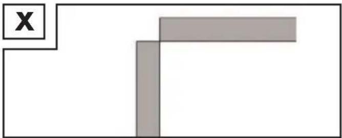
natural_image
Simple geometric diagram with a rectangle and diagonal line, no text or symbols presentDr. Christian Weyler
Katharina-Loth-Str. 15
DE-66386 St. Ingbert
DEUTSCHLAND
Dr. Christian Weyler
service.at@cmc-creative.de
service.ch@cmc-creative.de
Telefon: +49 (0) 6894/ 9989750
text_image
DPMIG Fe Ar80% Ø 0.8 2T 39 19.6 A V 2.8 1.4 m + m/min mm +0.1 +0.5 INDUCTANCE ARC LENGTHAVERTISSEMENT RISQUE DE BRÛLURES !
natural_image
Illustration of a soldering iron being inserted into a solder pad using a power tool (no text or symbols)natural_image
3D illustration of a tool interacting with a mechanical component (no text or symbols)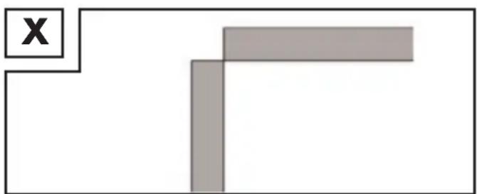
natural_image
Simple geometric diagram with two gray rectangles and a labeled 'X' in the top-left corner (no text or symbols within shapes)Dr. Christian Weyler
Katharina-Loth-Str. 15
DE-66386 St. Ingbert
ALLEMAGNE
Dr. Christian Weyler
other
| Sample | Composition (%) | | :--- | :--- | | Fe+MIX 80/20 | | | CrNi+MIX 98/2 | ∅0.8 | | CuSi+Ar100% | ∅1.0 | | AlMg+Ar 100% | | | AlSi+Ar100% | | | Al+Ar 100% | |text_image
DPMIG Fe Ar80% Ø 0.8 2T 39 19.6 A V 2.8 1.4 m + m/min mm +0.1 +0.5 INDUCTANCE ARC LENGTHWAARSCHUWING VERBRANDINGSGEVAAR!
natural_image
Illustration of a soldering iron being inserted into a circuit board (no text or symbols)natural_image
Two technical diagrams showing a tool interacting with a mechanical component, labeled 'W' and 'X', with no readable text or symbols.Overlappende lasverbindingen
Dr. Christian Weyler
Katharina-Loth-Str. 15
D-66386 St. Ingbert
DUITSLAND
Dr. Christian Weyler
natural_image
Illustration of a soldering iron being inserted into a solder pad, with no text or symbols present.natural_image
Two technical diagrams showing a tool interacting with a mechanical component, labeled 'W' and 'X', with no readable text or symbols.Dr. Christian Weyler
Katharina-Loth-Str. 15
66386 St. Ingbert
NĚMECKO
Dr. Christian Weyler
other
| Category | Value | | :--- | :--- | | FLUX | Ø0.6 | | Fe+CO | Ø0.8 | | Fe+MIX 80/20 | Ø0.9 | | ARC LENGTH | Ø1.0 |text_image
PMIG Fe Ar80% Ø 0.8 2T Fe+MIX 80/20 CrNi+MIX 98/2 Ø0.8 CuSi+Ar100% Ø1.0 AlMg+Ar 100% AlSi+Ar100% Al+Ar 100%text_image
DPMIG Fe Ar80% Ø 0.8 2T 39 19.6 A V 2.8 1.4 m + m/min mm +0.1 +0.5 INDUCTANCE ARC LENGTHnatural_image
Illustration of a soldering iron being inserted into a circuit board (no text or symbols)natural_image
Two technical diagrams showing a tool interacting with a mechanical component, labeled 'W' and 'X', with no readable text or symbols.Dr. Christian Weyler
Katharina-Loth-Str. 15
DE-66386 St. Ingbert
NIEMCY
Dr. Christian Weyler
text_image
PMIG Fe Ar80% Ø 0.8 2T Fe+MIX 80/20 CrNi+MIX 98/2 Ø0.8 CuSi+Ar100% Ø1.0 AlMg+Ar 100% AlSi+Ar100% Al+Ar 100%text_image
DPMIG Fe Ar80% Ø 0.8 2T 39 19.6 A V 2.8 1.4 mm + m/min mm +0.1 +0.5 INDUCTANCE ARC LENGTHVAROVANIE NEBEZPEČENSTVO POPÁLENIA!
natural_image
Illustration of a soldering iron being inserted into a circuit board (no text or symbols)natural_image
Two technical diagrams showing a tool interacting with a mechanical component, labeled 'W' and 'X', with no readable text or symbols.Dr. Christian Weyler
Katharina-Loth-Str. 15
66386 St. Ingbert
NEMECKO
Dr. Christian Weyler
other
| Sample | Concentration (%) | | :--- | :--- | | Fe+MIX 80/20 | | | CrNi+MIX 98/2 | Ø0.8 | | CuSi+Ar100% | Ø1.0 | | AlMg+Ar 100% | | | AlSi+Ar100% | | | Al+Ar 100% | |natural_image
Illustration of a soldering iron being inserted into a circuit board (no text or symbols)natural_image
Two technical diagrams showing a tool interacting with a mechanical component, labeled 'W' and 'X', with no readable text or symbols.Dr. Christian Weyler
Katharina-Loth-Str., 15
66386 St. Ingbert
ALEMANIA
Dr. Christian Weyler
text_image
DPMIG Fe Ar80% Ø 0.8 2T 39 19.6 A V 2.8 1.4 m + m/1 +0.1 +0.5 mm INDUCTANCE ARC LENGTHADVARSEL FARE FOR FORBRÆNDING!
natural_image
Illustration of a soldering iron being inserted into a solder pad (no text or symbols)natural_image
Two technical diagrams showing a tool interacting with a mechanical component, labeled 'W' and 'X', with no readable text or symbols.Dr. Christian Weyler
Katharina-Loth-Str. 15
DE-66386 St. Ingbert
TYSKLAND
Dr. Christian Weyler
other
| Sample | Concentration (%) | | :--- | :--- | | Fe+MIX 80/20 | | | CrNi+MIX 98/2 | Ø0.8 | | CuSi+Ar100% | Ø1.0 | | AlMg+Ar 100% | | | AlSi+Ar100% | | | Al+Ar 100% | |text_image
DPMIG Fe Ar80% Ø 0.8 2T 39 19.6 A V 2.8 1.4 m +0.1 +0.5 m/min mm INDUCTANCE ARC LENGTHnatural_image
Illustration of a soldering iron being inserted into a circuit board (no text or symbols)natural_image
Two technical diagrams showing a tool interacting with a mechanical component and a separate view of a rectangular block (no text or symbols present)Dr. Christian Weyler
Katharina-Loth-Str. 15
66386 St. Ingbert
GERMANIA
Dr. Christian Weyler
Nome: Riku Service snc
Indirizzo Internet: www.riku-service.com
E-Mail: info@riku-service.com
Telefono: 0039 (0) 4711430103
Sede: Germania
IAN 389215_2107
text_image
DPMIG Fe Ar80% Ø 0.8 2T 39 19.6 A V 2.8 1.4 m + m/min mm +0.1 +0.5 INDUCTANCE ARC LENGTHFIGYELMEZTETÉS ÉGÉSI SÉRÜLÉS VESZÉLYE!
natural_image
Illustration of a soldering iron being inserted into a circuit board (no text or symbols)natural_image
Two technical diagrams showing a tool interacting with a mechanical component, labeled 'W' and 'X', with no readable text or symbols.Dr. Christian Weyler
Katharina-Loth-Str. 15
DE-66386 St. Ingbert
NÉMETORSZÁG
Dr. Christian Weyler
text_image
DPMIG Fe Ar80% Ø 0.8 2T 39 19.6 A V 2.8 1.4 m + m/min mm +0.1 +0.5 INDUCTANCE ARC LENGTHOPOZORILO NEVARNOST OPEKLIN!
natural_image
Illustration of a soldering iron being inserted into a circuit board (no text or symbols)natural_image
Diagram of a mechanical tool interacting with a component, labeled 'W' in the corner (no text or symbols on the diagram itself)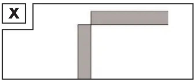
natural_image
Simple geometric diagram with a rectangle and an X symbol, no text or labels presentDr. Christian Weyler
Katharina-Loth-Str. 15
DE-66386 St. Ingbert
NEMČIJA
MULTI-WELDER WITH DOUBLE PULSE TECHNOLOGY PMPS 200 A1
Supplement for operating instructions
DE AT CH
MULTISCHWEISSGERÄT MIT DOPPELPULS-TECHNOLOGIE PMPS 200 A1
Multi-Welder with Double Pulse Technology PMPS 200 A1
Supplement to the operating manual
Use of the adapter 37 allows adjustment of the PMPS 200 A1 welding unit for use of welding wire rolls with 450 g or 1 kg wire.
Instructions for assembly of the adapter:
First release the fixing for welding wire spool 28 and remove the welding wire reel adapter 35. Now install the adapter 37 as shown in figure AD. Bring the adapter into position and fasten it with the fixing for welding wire spool 28. In order to install the unpacked 450 g or 1 kg wire roll, first
release the latch 38 by pushing it, followed by a brief turn to the left. Then remove the disc 39. Place the wire roll on the corresponding holder. Ensure that the roll is unwound on the side of the wire outlet 29 and the end of the welding wire is above the welding coil. Return the disc 39 to its position and fasten the latch 38 by pressing, followed by a brief turn to the right. Continue as described in the chapter "Inserting welding wire", starting with the item "Undo the adjustment screw 25 and swing it downwards (see Fig. I)". A fully installed wire roll (not enclosed) is illustrated in figure AE.