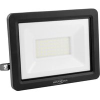
WFL1600S - Lamp ANSMANN - Free user manual and instructions
Find the device manual for free WFL1600S ANSMANN in PDF.
| Product type | Wall spotlight with motion sensor |
| Brand | Ansmann |
| Model | WFL1600S |
| Power | 20 W |
| Supply voltage | 220-240 V~, 50/60 Hz |
| Lighting type | Integrated non-replaceable LED |
| Color temperature | 5000 K (daylight) |
| Color rendering index (CRI) | >80 Ra |
| Luminous flux | 1800 lm |
| Protection rating | IP54 (dust and splash water protected) |
| Impact protection rating | IK05 |
| Protection class | I (requires grounding) |
| Glass dimensions (L x W x H) | 177 x 127 x 4 mm |
| Dimensions with bracket (L x W x H) | 202 x 205 x 34 mm |
| Weight | 0.88 kg |
| Sensor range | 12 m max |
| Detection angle | 100° horizontal, +10° to -80° vertical |
| Max. mounting height | 3 m |
| Operating temperature | -20 °C to +50 °C |
| Settings | Lighting duration (10 s to 5 min), light threshold (0-2000 lux) |
| Glass material | Non-replaceable safety glass |
| Warranty | 10 years |
| Usage | Indoor and outdoor |
Frequently Asked Questions - WFL1600S ANSMANN
User questions about WFL1600S ANSMANN
0 question about this device. Answer the ones you know or ask your own.
Ask a new question about this device
Download the instructions for your Lamp in PDF format for free! Find your manual WFL1600S - ANSMANN and take your electronic device back in hand. On this page are published all the documents necessary for the use of your device. WFL1600S by ANSMANN.
USER MANUAL WFL1600S ANSMANN
natural_image
Three black rectangular lighting fixtures with visible LED indicators and cables, arranged on a white background (no text or symbols)WALL-FLOODLIGHT WITH SENSOR
1600-0283: WFL800S
1600-0284: WFL1600S
1600-0285: WFL2400S
text_image
1 2 2 5 4 3WFL800S | WFL1600S | WFL2400S
INHALTSVERZEICHNIS
Lieferumfang....3
text_image
Technical diagram illustrating the installation of a device with screw fasteners and a close-up view of its internal components.
ANSCHLUSS
text_image
≤ 100° ≤ 90°natural_image
Mechanical diagram showing a lever mechanism with a rotating arrow and handle (no text or symbols)natural_image
Simple diagram with a circular element and curved arrow, no text or symbols present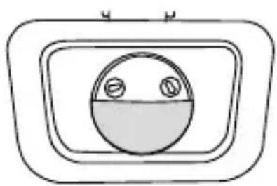
natural_image
Simple line drawing of a circular object with two small circles inside, enclosed in a rounded rectangular frame (no text or symbols)natural_image
Simple line drawing of a circular shape with two small circles on top and bottom (no text or symbols)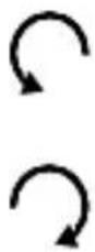
Längere Leuchtdauer
Kürzere Leuchtdauer
natural_image
Simple circular diagram with two small circles on top and bottom, no text or symbols present.
WALL FLOODLIGHT WITH SENSOR
WFL800S | WFL1600S | WFL2400S
CONTENTS
Scope of delivery.... 14
Signs and symbols.... 15
Intended use 15
Safety instructions....15
Product description.... 17
Installation 17
Connection....19
Setting the floodlight 20
Setting the sensor 20
Detection range 22
Cleaning....22
Technical data....23
Disposal....24
DISCLAIMERS 24
WARRANTY INFORMATION 24
SCOPE OF DELIVERY
1x Wall floodlight with sensor
1x Instruction manual
First unpack the product and check it for completeness and damages. Do not operate the product if it is damaged. Contact your retailer should you find any damage to the product.
SIGNS AND SYMBOLS
Please adhere to the following signs and warnings used in the instruction manual, on the product and on the packaging.
i = Information
Additional useful information about the product
√ = Notice
This notice informs the user of possible damages of all kinds
! = Warning
Caution - Danger! Can result in serious injury or death
∅ = Protection class I
= Risk of electric shock
△ = Do not look into the light beam
Do not operate if glass is broken
INTENDED USE
The product serves to illuminate driveways, passageways, open spaces, etc. The sensor enables the floodlight to be turned on automatically or only when needed.
The product is designed exclusively for household use; it is not suitable for commercial purposes.
SAFETY INSTRUCTIONS
Carefully read the entire instruction manual before first operating the product. It contains important information on handling the product.
If you give the product to third parties, you must include this instruction manual.
- Keep children away from the product and the packaging. The product is not a toy. Children should be supervised to ensure that they do not play with the product.
-
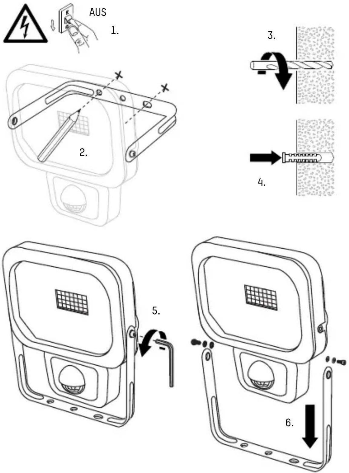
Risk of fatal injury due to electric shock! Always make sure that you interrupt the power supply before installation or other product-related actions. Protect the fuse box against unauthorized activation by third parties, e.g. with a warning sign.
-
Before connecting the product with the power supply, always make sure that the supply voltage complies with the information on the rating plate.
- The mounting surface and materials must be able to securely hold the product. In case of doubt, consult an expert.
- Warning: Risk of fatal injury due to electric shock! Take care not to damage water, electricity or telecommunications lines while drilling holes. Use a cable locator.
- This product complies with protection class IP54: Protected against the ingress of dust into hazardous and sensitive components. Splash-proof. Do not immerse the product in water.
The IP protection class is only ensured when the product is correctly installed. - Never touch the product with wet or damp hands.
- Always ensure that the power cord is not taut nor comes into contact with sharp objects, chemicals or solvents.
- Regularly check the power cord and power plug for damages.
- To avoid hazards, the flexible exterior cord of this floodlight, if damaged, may only be replaced by the manufacturer, its service representative or a comparable professional.
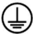
This product complies with protection class I and must therefore be connected to the protective earth conductor.
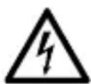
Risk of fatal injury due to electric shock! Improper use, operation or installation poses a risk of potentially fatal electric shock. The product may be connected by a professional electrician only!
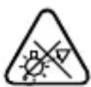
Do not look directly into the beam of light.
Do not shine the light in the faces of others. Looking into the beam of light for too long may cause damage to the retina due to blue light.

The safety glass is non-replaceable. If the safety glass is damaged, dispose of the product.
- Safe operation cannot be guaranteed if the product shows any kind of damage. If the product is damaged, it must be disposed of or repaired.
- Do not repair the product yourself! Have repairs carried out by a professional electrician.
- The luminary is non-replaceable. The entire product must be replaced when the luminary reaches the end of its service life.
- Caution! Use a H05RN-F 3G 1 mm ^2 or higher category connection cable for connection only.

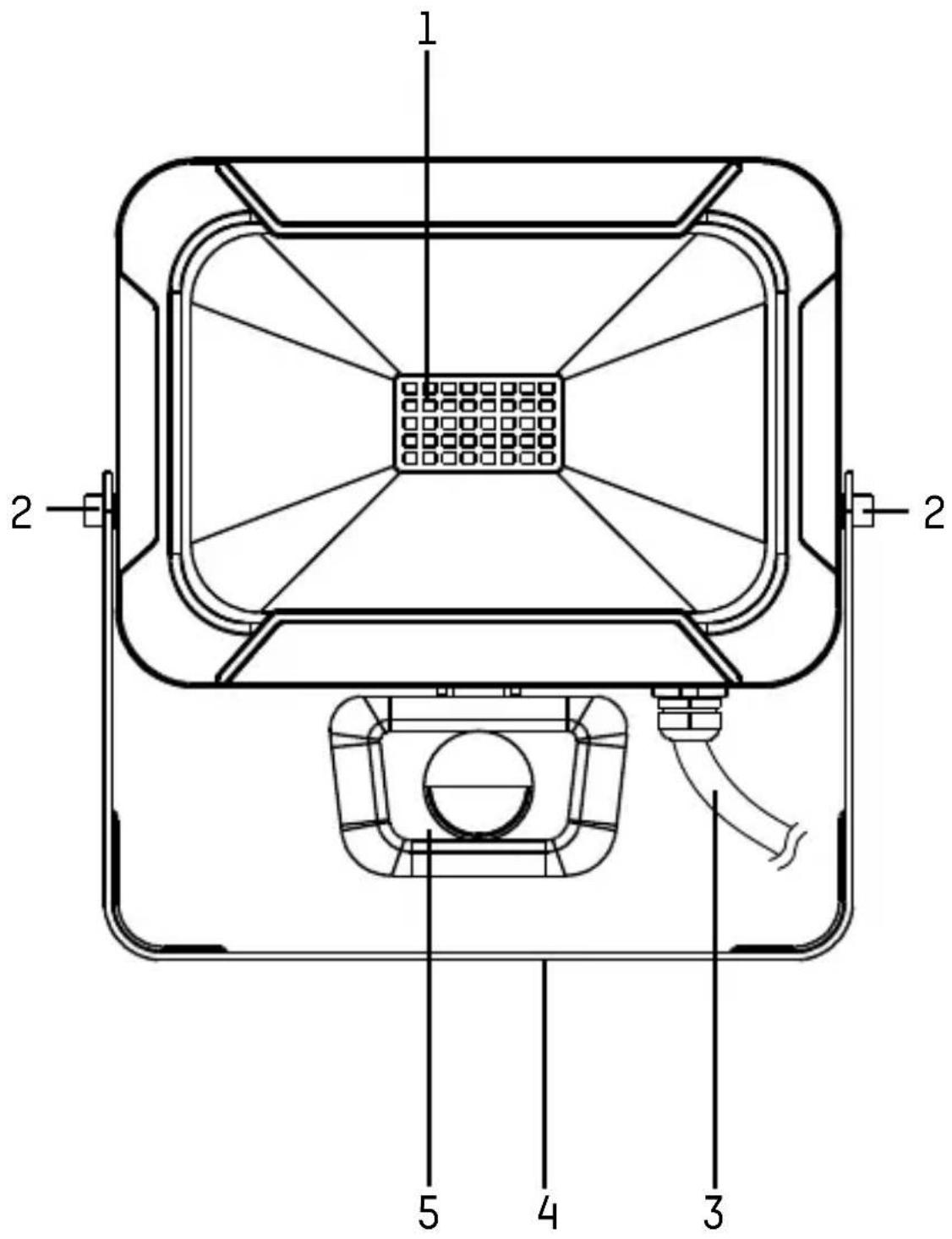
PRODUCT DESCRIPTION
(see page 2)
1 LEDs
4 Mounting bracket
2 Set screws
5 Sensor
3 Power cord

INSTALLATION
- Interrupt the power supply to the cable at the fuse box and secure it against reconnection by third parties.
- Select a suitable location for product installation.
Please note:
Other light sources (e.g. lanterns) may impair the sensor's functionality. Do not install the product in areas directly influenced by other sources of light.
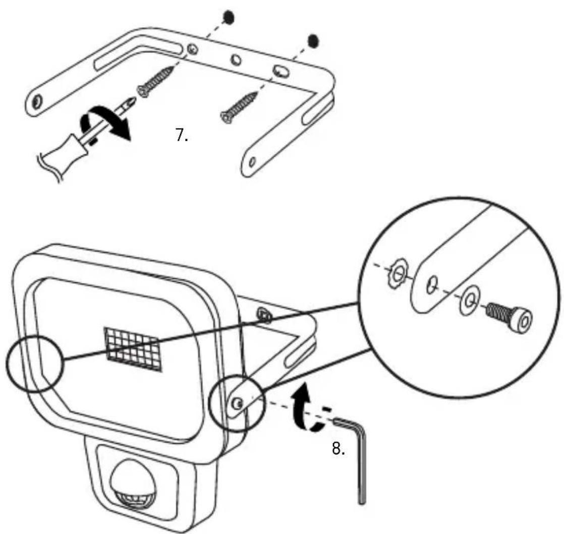
The mounting holes in the bracket have a diameter of 5 mm. Select suitable mounting materials.
Mounting materials are not included. This manual shows by way of example installation using 2 screws and 2 wall anchors. If necessary, you can use other mounting materials.
text_image
Technical diagram illustrating the assembly of a device with labeled parts and steps 7 and 8, showing screwdriver installation and component disassembly.
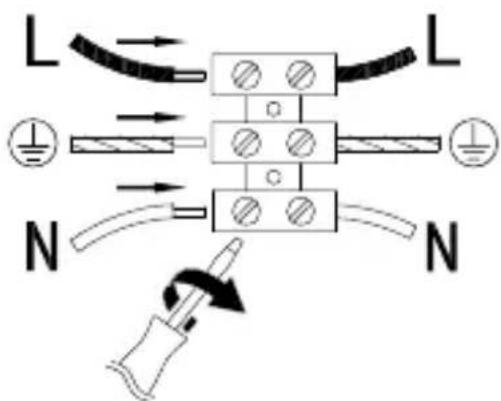
CONNECTION
- Connect the wires according to the markings:
L Phase (brown)

Grounding (yellow-green)
N Neutral (blue)
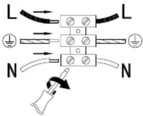
text_image
L L N N• Turn back on the power supply.

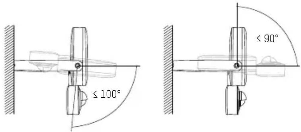
SETTING THE FLOODLIGHT
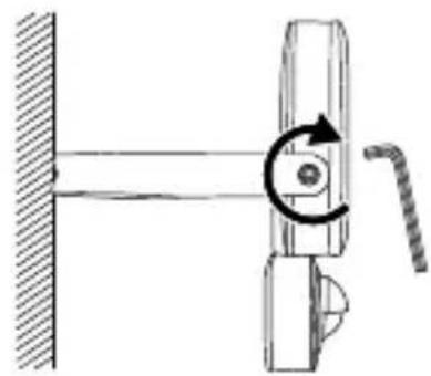
- Loosen the set screws.
text_image
≤ 100° ≤ 90°- Set the desired angle of the floodlight (-100° to +90°).
natural_image
Mechanical diagram showing a lever mechanism with a rotating arrow and handle (no text or symbols)- Tighten the set screws with a hex key.

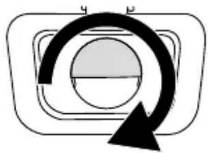
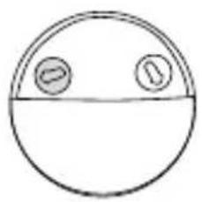
SETTING THE SENSOR
natural_image
Pure electrical circuit symbol diagram without any text or labels
natural_image
Simple line drawing of a circular object with two small circles inside, enclosed in a rounded rectangle (no text or symbols)- Turn the sensor cover 180^ .
• Light ON time after activation: 10 ± 5 seconds to 5 ± 1 minutes

natural_image
Simple line drawing of a circular shape with two small circles on top and bottom (no text or symbols)
Longer light ON time
Shorter light ON time
Please note: Each time the sensor is tripped, the light ON time is extended by the set duration.
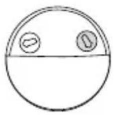
- Lighting conditions in which the sensor is activated (0 to 2000 lx).
natural_image
Simple circular diagram with two small circles on top and bottom, no text or symbols present.
Activated day and night
Only activated at night
- Turn the knob clockwise until it stops.
- Wait until the onset of the lighting conditions in which the sensor should be activated.
- While another person is moving in front of the sensor, slowly turn the knob counter-clockwise until the product turns on.
- Turn the sensor cover 180^ to the upper position.
- If necessary, align the product to the left or right.

DETECTION RANGE
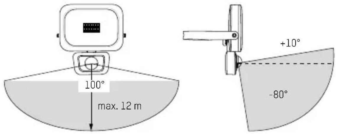
text_image
100° max. 12 m +10° -80°Please note: The sensor reacts with greater sensitivity to movements across its sensor field.

CLEANING
- Always disconnect the power supply at the fuse box before cleaning the product. Secure the product against unintended reactivation by placing a warning sign on the fuse box.
- Use only a soft, dry or slightly damp cloth (where necessary with a little mild dishwashing detergent) to clean the product. Never use any abrasive cleaners or solvents to clean the product.

TECHNICAL DATA
| Model | 1600-0283:WFL800S | 1600-0284:WFL1600S | 1600-0285:WFL2400S |
| Supply voltage 220-240 V~, 50/60 Hz | |||
| Power output in watts 10 W 20 W 30 W | |||
| IP protection class IP54 (splashproof) | |||
| IK protection class IK05 | |||
| Protection class I | |||
| Luminary type LED | |||
| Colour temperature 5000 K | |||
| Colour rendering index (CRI) >80 Ra | |||
| Nominal luminous flux 900 lm 1800 lm 2700 lm | |||
| Max. projection area 250 cm ^2 | 420 cm ^2 | 585 cm ^2 | |
| Installation site Indoors and outdoors | |||
| Installation height max. 3 m | |||
| Sensor range max. 12 m | |||
| Sensor detection angle Horizontal: 100°Vertical: +10° to -80° | |||
| Operating temperature -20 to +50 °C | |||
| Glass dimensions124 x90 x4 mm | 177 x127 x4 mm | 201 x146 x4 mm | |
| (W x H x D) – approx. | |||
| Dimensions with bracket (W147 x166 x42 mm | 202 x205 x34 mm | 231 x252 x41 mm | |
| Weight – approx. | 0.51 kg 0.88 kg | 1.31 kg | |

DISPOSAL
At the end of its service life, dispose of the light in keeping with all legal requirements. The dustbin symbol indicates that waste electrical and electronic equipment may not be disposed of with normal household waste within the EU. Please use local recycling and collection points or contact the retailer where you purchased the product.
You thus fulfill your statutory obligations and contribute to protection of the environment.

DISCLAIMERS
The information contained in this instruction manual is subject to change without prior notice. ANSMANN assumes no liability for direct, indirect, accidental or other types of damage or consequential damage that result from improper handling of the product or failure to comply with the information contained in this instruction manual. We assume no liability and grant no warranty claims in cases of improper use of the product.

WARRANTY INFORMATION
We offer a ten-year warranty on the product. Damages to the product due to failure to observe the instruction manual will void the warranty. This does not affect your legal warranty right.
You can find our warranty terms online at www.ansmann.de
1600-0283 1600-0284

The product meets the conditions of the European Union.

1600-0285
TRADUCTION DE LA NOTICE ORIGINALE
SPOT MURAL AVEC CAPTEUR
WFL800S | WFL1600S | WFL2400S
TABLE DES MATIÈRES
text_image
Technical diagram illustrating the assembly of a device with labeled parts and steps 7 and 8, showing screwdriver installation and component disassembly.
RACCORDEMENT
text_image
≤ 100° ≤ 90°natural_image
Mechanical diagram showing a lever mechanism with a rotating arrow and handle (no text or symbols)natural_image
Pure diagram of a circular component with curved arrows indicating rotation or direction (no text or symbols)
natural_image
Simple line drawing of a circular object with two small circles inside, enclosed in a rectangular frame (no text or symbols)natural_image
Simple circular diagram with two small circles on top and bottom, no text or symbols present.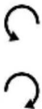
natural_image
Simple circular diagram with two small circles on top and bottom, no text or symbols present.
Activé jour et nuit
WFL800S | WFL1600S | WFL2400S
ÍNDICE DE CONTENIDO
Volumen de suministro....36
text_image
Technical diagram illustrating screwdriver tool installation steps with labeled components and magnified views
CONEXIÓN
text_image
≤ 100° ≤ 90°natural_image
Mechanical diagram showing a lever mechanism with a rotating arrow and handle (no text or symbols)natural_image
Pure diagram of a circular component with a curved arrow indicating rotation or cycle (no text or symbols)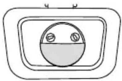
natural_image
Simple line drawing of a circular object with two small circles inside, enclosed in a rounded rectangular frame (no text or symbols)natural_image
Simple line drawing of a circular shape with two small circles on top and bottom (no text or symbols)
Autonomía más larga
Autonomía más corta
natural_image
Simple line drawing of a circular shape with two small circles on top and bottom (no text or symbols)
WFL800S | WFL1600S | WFL2400S
ÍNDICE
text_image
Technical diagram illustrating the assembly of a device with screwdriver and labeled parts, including steps 7 and 8.i LIGAÇÃO
text_image
≤ 100° ≤ 90°natural_image
Mechanical diagram showing a lever mechanism with a rotating arrow and handle (no text or symbols)natural_image
Pure diagram of a circular component with curved arrows indicating rotation or direction (no text or symbols)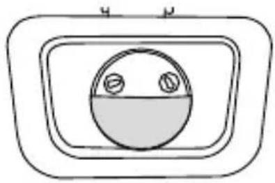
natural_image
Simple line drawing of a circular object with two small circles inside, enclosed in a rectangular frame (no text or symbols)• Gire a cobertura do sensor por 180°.
natural_image
Simple line drawing of a circular shape with two small circles on top and bottom (no text or symbols)
natural_image
Simple line drawing of a circular shape with two small circles on top and bottom (no text or symbols)
WFL800S | WFL1600S | WFL2400S
INNEHÅLLSFÖRTECKNING
text_image
Technical diagram illustrating screwdriver tool installation steps with labeled components and magnified views
ANSLUTNING
text_image
≤ 100° ≤ 90°natural_image
Mechanical diagram showing a lever mechanism with a rotating arrow and handle (no text or symbols)natural_image
Simple diagram with a circular shape inside a rounded rectangle and a curved arrow pointing downward (no text or symbols)
natural_image
Simple line drawing of a circular object with two small circles inside, enclosed in a rounded rectangle (no text or symbols)• Vrid sensorkåpan 180°.
natural_image
Simple line drawing of a circular shape with two small circles on top and bottom (no text or symbols)
natural_image
Simple circular diagram with two small circles on top and bottom, no text or symbols present.
WFL800S | WFL1600S | WFL2400S
INDICE
text_image
Technical diagram illustrating the assembly of a device with labeled parts and steps 7 and 8, showing screwdriver installation and component disassembly.
COLLEGAMENTO
text_image
≤ 100° ≤ 90°natural_image
Mechanical diagram showing a lever mechanism with a rotating arrow and handle (no text or symbols)natural_image
Pure diagram of a circular component with curved arrows indicating rotation or direction (no text or symbols)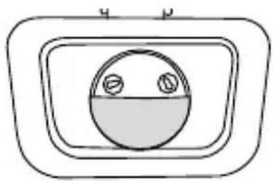
natural_image
Simple line drawing of a circular object inside a rectangular frame, no text or symbols presentnatural_image
Simple line drawing of a circular shape with two small circles on top and bottom (no text or symbols)
natural_image
Simple line drawing of a circular shape with two small circles on top and bottom (no text or symbols)
WFL800S | WFL1600S | WFL2400S
INHOUDSOPGAVE
text_image
Technical diagram illustrating the assembly of a device with labeled parts and steps 7 and 8, showing screwdriver installation and component disassembly.i AANSLUITING
text_image
≤ 100° ≤ 90°- Stel de gewenste hoek van de muurstraler in (-100^ tot +90^) .

natural_image
Mechanical diagram showing a lever mechanism with a rotating arrow and handle (no text or symbols)natural_image
Pure electrical circuit symbol diagram without any text or labels
natural_image
Simple line drawing of a circular object with two small circles inside, enclosed in a rectangular frame (no text or symbols)natural_image
Simple line drawing of a circular shape with two small circles on top and bottom (no text or symbols)
natural_image
Simple circular diagram with two small circles on top and bottom, no text or symbols present.
WFL800S | WFL1600S | WFL2400S
SISÄLLYS
text_image
Technical diagram illustrating the assembly of a device with labeled parts and steps 7 and 8, showing screwdriver installation and component disassembly.i LIITÄNTÄ
text_image
≤ 100° ≤ 90°- Aseta valonheitin haluttuun kulmaan (-100^ - +90^) .

natural_image
Mechanical diagram showing a lever mechanism with a rotating arrow and handle (no text or symbols)natural_image
Pure diagram of a circular component with curved arrows indicating rotation or direction (no text or symbols)
natural_image
Simple line drawing of a circular object inside a rectangular frame with two small circles on its side (no text or symbols)natural_image
Simple line drawing of a circular shape with two small circles on top and bottom (no text or symbols)
Pidempi valaisuaika
natural_image
Simple circular diagram with two small circles on top and bottom, no text or symbols present.
WFL800S | WFL1600S | WFL2400S
INNHOLDSFORTEGNELSE
Leveranseinnhold 102
Tegnforklaring 103
Tiltenkt bruk 103
Sikkerhetsmerknader 103
Produktbeskrivelse 105
Montering....105
Tilkobling 107
Justere lyskaster 108
Justere sensor 108
Sensorområde 110
Rengjøring 110
text_image
Technical diagram illustrating the assembly of a device with labeled parts and steps 7 and 8, showing screwdriver installation and component disassembly.
TILKOBLING
- Koble til lederne i samsvar med merkingene:
L Fase (brun)

Jord (gul-grønn)
N Nøytral (blå)
text_image
L L N Ntext_image
≤ 100° ≤ 90°- Juster lyskasteren i ønsket vinkel (-100° til +90°).

natural_image
Mechanical diagram showing a lever mechanism with a rotating arrow and handle (no text or symbols)natural_image
Simple diagram with a circular shape inside a rounded rectangle and a curved arrow pointing downward (no text or symbols)
natural_image
Simple line drawing of a circular object with two small circles inside, enclosed in a rounded rectangle (no text or symbols)• Vri sensordekselet rundt 180°.
- Belysningsvarighet etter aktivering: 10±5 sekunder til 5±1 minutter
natural_image
Simple line drawing of a circular shape with two small circles on top and bottom (no text or symbols)
Lengre belysningsvarighet
Kortere belysningsvarighet
natural_image
Simple circular diagram with two small circles on top and bottom, no text or symbols present.
WFL800S | WFL1600S | WFL2400S
INDHOLDSFORTEGNELSE
Leveringsomfang 113
Tegnforklaring 114
text_image
Technical diagram illustrating the installation of a device with screw fasteners and a close-up view of its internal components.
TILSLUTNING
text_image
≤ 100° ≤ 90°natural_image
Mechanical diagram showing a lever mechanism with a rotating arrow and handle (no text or symbols)INDSTILLING AF SENSOR

natural_image
Pure electrical circuit symbol diagram without any text or labels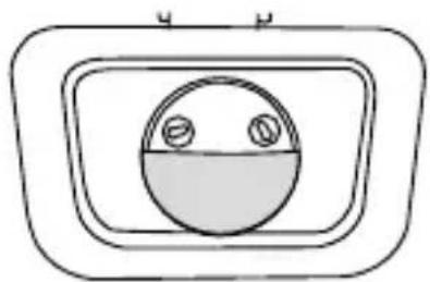
natural_image
Simple line drawing of a circular object with two small circles inside, enclosed in a rectangular frame (no text or symbols)- Drej sensordækslet 180°.
natural_image
Simple line drawing of a circular shape with two small circles on top and bottom (no text or symbols)
natural_image
Simple circular diagram with two small circles on top and bottom, no text or symbols present.
Kundenservice | Customer service:
ANSMANN AG
Industriestrasse 10
97959 Assamstadt
Germany
Support & FAQ: ansmann.de
E-Mail: hotline@ansmann.de
Hotline: +49 (0) 6294 / 4204 3400
MA-1600-0283/-0284/-0285/V2/04-2022