USER MANUAL RS II VSTD HAYWARD
KEEP THIS MANUAL FOR FUTURE REFERENCE
WARNING: Electrical Hazard. Failure to follow instructions can result in serious injury or death. FOR USE WITH SWIMMING POOLS
WARNING - Disconnect the pump from the main power supply completely before servicing the pump or filter.
WARNING - FOR PROFESSIONAL USE - All electrical connections must be done by a qualified electrician according to local electrical standard or, failing that, to the International Standard IEC 60364-7-702.
WARNING - Be certain the machine is only plugged into a protected 230~V outlet that is protected from short-circuits. The pump is to be supplied by an isolating transformer or supplied through a residual current device (RCD) having a rated residual operating current not exceeding 30~mA .
WARNING - Children should be supervised to ensure that they do not play with the appliance. Keep fingers and foreign objects away from openings and moving parts.
WARNING - Motor must be suitably grounded. Connect ground wire to green grounding screw and for cord connected units use properly grounded outlet.
WARNING - Use a motor bonding lug to connect motor with other bonded parts using the appropriate size conductor as required by electrical codes.
WARNING - When making these electrical connections, refer to the diagram given under the lid of the motor terminal box. Be sure to check the electric connections are tight and sealed before powering up. Replace all covers before operation.
WARNING – Make sure that the power supply voltage required by the motor corresponds to that of the distribution network and that the power supply cables matches the power and current of the pump.
WARNING - Read and follow all instructions in this owner's manual and on the equipment. Failure to follow instructions can cause serious injury or death.
This document should be given to the owner of the swimming pool and must be kept by the owner in a safe place.
WARNING - The appliance can be used by children aged from 8 years and above and persons with reduced physical, sensory or mental capabilities, or lack of experience and knowledge, if they have been given supervision or instruction concerning use of the appliance in a safe way and understand the hazards involved.
WARNING - Cleaning and user maintenance shall not be made by children without supervision.
WARNING - The pump is intended for continuous operation at Maximum Water temperature 35^
WARNING - Use Only Genuine Hayward® Replacement Parts.
WARNING - If the supply cord is damaged it must be replaced by the manufacturer, service agent, or similarly qualified persons in order to avoid a hazard.
WARNING - For disconnection from main power supply an external switch having a contact separation in all poles that provide a full disconnection under overvoltage category III conditions must be incorporated in the fixed wiring in accordance with the wiring rules.
WARNING - Do not operate the swimming pool pump if the power cord or the housing of the motor connection box is damaged. This can cause an electric shock. A damaged power cord or motor connection box must be replaced by a service agent or a similarly qualified person immediately in order to avoid a hazard.
WARNING - This pool motor is NOT equipped with a Safety Vacuum Release System (SVRS). SVRS helps prevent drowning due to body entrapment on underwater drains. In some pool configuration, if a person's body covers the drain, the person can be trapped by suction. Depending on your pool configuration, a SVRS may be required to meet local requirements
WARNING – This pump contains a battery that, for safety reasons, any manipulation must be carried out by an authorized technical service..
USE ONLY HAYWARD
Genuine REPLACEMENT PARTS
GENERAL POINTS
Congratulations, you have just acquired a Hayward® variable speed pump.
Hayward variable speed pumps have a state-of-the-art permanent-magnet motor with AC electronic switching. This motor is controlled by a microprocessor combined with a frequency variator providing the following characteristics:
- Rotation speed is displayed on the control display
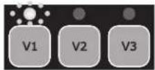
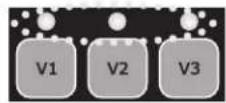
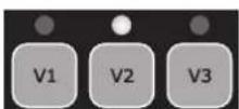
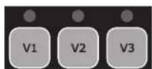
- 3 factory preset rotation speeds (buttons V1, V2, V3), as well as custom speeds set by the user
- Regular priming each time you switch on, with adjustable speed and duration
- Skimmer function, which skims the water's surface
Programmable Timer function
- Current power usage displayed
- Partial and total power consumption displayed
- Running time of the pump displayed
Low noise level
- Construction standard TEFC IP55
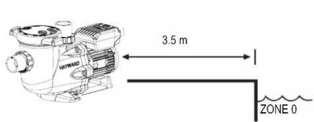
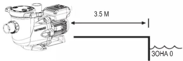
Install the pump at a suitable distance from the pool to reduce the distance between the suction point and the pump as much as possible to avoid pointless excessive pressure drops on the hydraulic circuit.
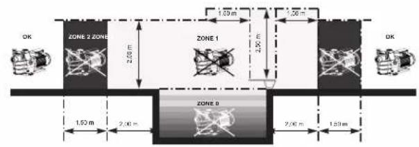
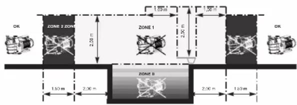
However, it is essential to comply with the safety distance required by the current installation standard (3.5 m minimum). Install and use the product at an altitude less than 2000 m
Install the pump in a dry, well-ventilated place. The motor requires the air to circulate freely around it to allow natural ventilation. Clear a space of at least 0.5m around the pump. Check regularly that no objects, leaves or other debris are blocking the motor cooling system.
The pump must be installed to ensure that the external disconnection switch incorporated into the fixed unit is visible and easily accessible. The switch must be located near to the pump.
The pump must be permanently installed on a concrete base using 8mm lag screws suitable for concrete, screwed into drilled implantation holes. Lock washers must be used to prevent the installation lag screws working loose over time. If the pump has to be mounted on a wooden board, 0.8mm hexagonal wood screws must be used combined with lock washers to prevent the screws working loose over time.
Install the pump under shelter to avoid the control unit being subject to heavy splashing.
The acoustic pressure of Hayward® pumps is less than 70 dBA.
Necessary measures:
- Connect the pump to the earth: Never operate the pump unless it is connected to the earth.
- Connect the pump with a H07RN-F 3G1,5mm² type cable.
- Include a 30 mA differential protection to protect people against electric shocks which may be caused by a breach of the equipment's electrical insulation.
- Include short-circuit protection (the rating is determined according to the value given on the nameplate on the motor).
- Include a means of disconnection from the power supply having an opening distance on the contacts of all the poles ensuring the power supply is completely cut off under the conditions of a category III overvoltage.
WARNING: Wait 5 minutes after having totally disconnected the pump from the power supply before carrying out any operation on the motor or the connection box: Danger of electric shock which may cause death.
The electric motors fitted to our pumps have thermal protection. This protection reacts in the event of overload or abnormal temperature rise in the motor winding. This protection automatically resets when the winding temperature drops. Whatever the type of motor used, if the regulations require it, a magnetic thermal protection must be installed in addition to the measures described above, which must be calibrated according to the information on the motor's nameplate.
The table on page 169 gives the various characteristics of the motors fitted to our pumps.
USE ONLY HAYWARD
Genuine REPLACEMENT PARTS
Electrical connection: Ensure that the supply voltage required by the motor corresponds to that of the distribution network and that the section and length of the power cable are adapted to the power and current of the pump.
All the electrical connections on the pump and any change of power cable must be done by a qualified professional to avoid any danger.
When carrying out the electrical connections, comply with the identification under the connection terminals.
Check that the electrical connections are correctly tightened and watertight before switching on the power.
Ensure the cable runs correctly through the opening and ferrite provided for this purpose. The cable gland ensures watertightness around the cable, and the ferrite acts as a filter against electromagnetic disturbance.
Any pre-wiring on our pumps must be removed when the pump is permanently connected to the power supply. This preparation is only used for testing at the factory during the manufacturing phases.
INSTALLATION
Install the pool pump so as to reduce pressure drops to a minimum whilst complying with the distances specified in the installation standard, namely 3.5m minimum between the pump and the pool. The suction pipe must be installed with a slight uphill incline towards the pump axis. Ensure that the connections are correctly tightened and watertight. However, avoid excessively tightening the pipes. For plastic materials, use Teflon only to ensure watertightness. The diameter of the suction pipe shall depend on that of the discharge pipe. Avoid damp or non-ventilated locations. The motor requires the cooling air to circulate freely. Install the pump under shelter to avoid the control unit being subject to heavy splashing.
INSTRUCTIONS FOR START-UP AND PRIMING: Fill the body of the strainer with water up to the level of the suction pipe. Never run the pump without water, as the water is necessary for cooling and lubrication of the mechanical shutter. Open all the suction and discharge pipe valves, and the filter air purge valve if there is one. (Any air in the suction pipes must be eliminated). Start up the generator and wait a reasonable time for priming. Five minutes is not excessive for priming (this time depends on the suction head and the length of the suction pipe). If the pump does not start or does not prime, please refer to the troubleshooting guide.
USING THE CONTROL PANEL
1. INTRODUCTION
Hayward's variable speed pump is operated through a control panel that visually displays the operating settings and allows you to adjust them as well as program the Timer mode.
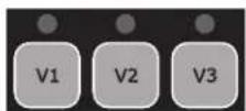
| 1 P | power on LED |
| 2 LCD display screen |
| 3 Choosing the speed |
| 4 Switching between Manual/Timer modes |
| 5 Up/down buttons |
| 6 Start/Stop button |
| 7 Display settings button |
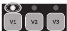
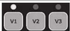
| 8 Selected speed LEDs |

The pump is delivered with DEFAULT SETTINGS(factory settings):
rpm: Rotations per minute
| Priming time (seconds) | Priming speed (rpm) | V1 (rpm) | V2 (rpm) | V3 (rpm) | Skimmer time (minutes) | Skimmer cycle (hours) | Skimmer speed (rpm) |
| 240 3000 | 1500 2400 3000 | 0 15 1hr 2800 | | | | | |
USE ONLY HAYWARD
Genuine REPLACEMENT PARTS
In manual mode, the user can switch the pump on or off manually, according to when the pool is being used.
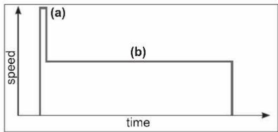
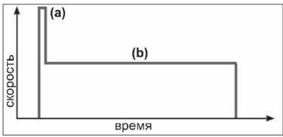
- When you switch the pump on, it launches a priming phase (a). You can adjust this phase (speed and duration, section 4.2). Priming may be interrupted during start up (section 3.2) or deactivated in the settings.
- The pump speed then stabilizes to a constant rate (b) (stabilization to V2 by default). The user can choose and adjust the speed (section 3.3).
- After switching off and then restarting, the pump will stabilize at the last recorded rate.
2.2 Skimmer
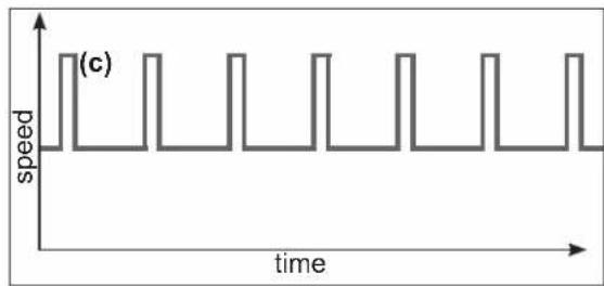
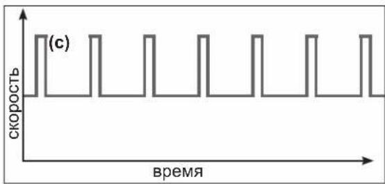
The Skimmer function allows the pump to skim just the water's surface, which is especially useful for preventing dirt from accumulating and stagnating at the surface of the pool.
- The function is automatic: the pump will run at a higher speed (c) for a while and according to a set cycle - both of which you can adjust.
- After running at a higher speed, the pump will adjust to its normal rate - this is the case in both the Manual and Timer modes.
- You can deactivate the Skimmer function (see settings in section 4.3).
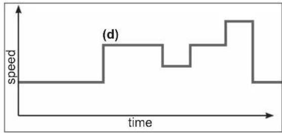
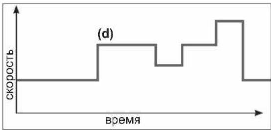
2.3 Timer mode
When using the Timer mode, the pump is run automatically 24/7. The user can program (d) the different speed presets. They are selected depending on the installation (heating mode, energy-saving mode etc.) and according to the times the pool is used.
- If the Skimmer function is activated, its sequence will superimpose on the timer one.
- You can stop the pump (pause it) in the Timer mode. When you start it up again, it will run at the speed of the current 'Timer' mode.
- For information on how to program the Timer mode, see section 4.5.
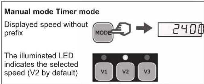
2.4 Switching between Manual and Timer modes
You can switch between modes by pressing the button MOSES hown below:
hown below:
Displayed speed with prefix 't'

The LEDs are switched off

USE ONLY HAYWARD
Genuine REPLACEMENT PARTS
CAUTION: Before carrying out any electrical work on the pump, unplug the power cord and wait 5 min.
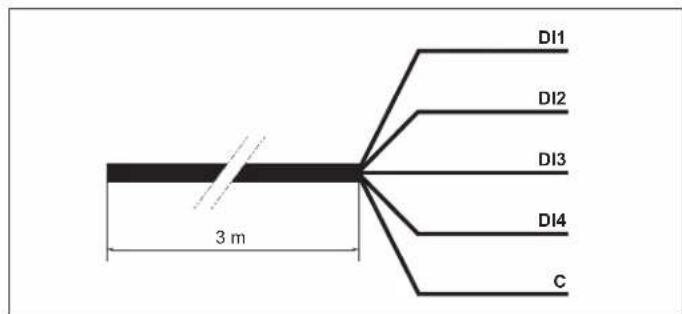
The filtration pump is equipped with a 3-m long 5-wire cord for connecting the 4 digital inputs or potential-free dry contacts (Open/Closed).
- Assign the speed and flow required for the peripheral devices, such as a heat pump, roller blind or robotic vacuum, etc. to work properly.
- Install a user interface control unit. These digital inputs are used to control, from a distance of 3m , the Run/Stop function as well as the 3 speeds (V1-V2-V3).
| Assigning the wires |
| DI1 Brown Speed | V1 | |
| DI2 Green Speed | V2 | |
| DI3 White Speed | V3 | |
| DI4 Red Run/Stop | | |
| C Black Common | | |
N.B.
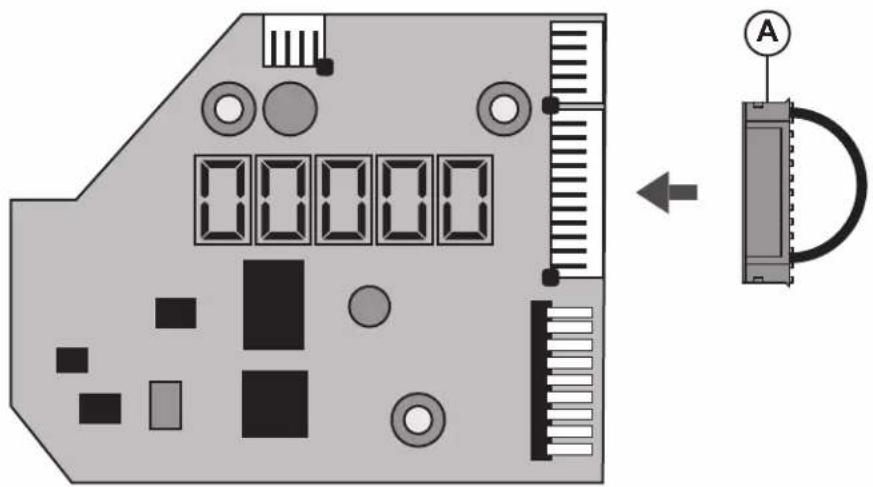
- If the digital inputs are partially used, electrically insulate the unused wires.
- If the digital inputs are unused, insert the connector (A) instead of the 5-wire cord (see figure below).
USE ONLY HAYWARD
Genuine REPLACEMENT PARTS
Operation with the digital inputs
| The digital inputs can be operated in Manual or Timer mode.
They have the highest priority level: they act as MASTER over all the functions currently in use.
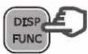
Only the Run/Stop and DISP/FUNC buttons remain active. | →
→
→
→ | RUN
STOP
DISP
FUNC |
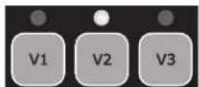
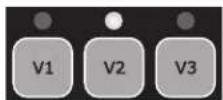
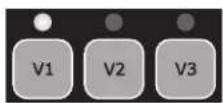
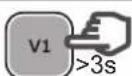
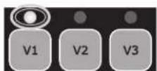
| When a digital input is used, the LED associated with the speed in question blinks rapidly (DI1 = V1, DI2 = V2 or DI3 = V3). | →
→
→
→ | V1
V2
V3 |
| To obtain an action through the digital inputs, the DI4 input must be closed. | DI4 Run/StopClosed |
| If several digital inputs are switched simultaneously, only one will be carried out in the order of priority specified in the table opposite. | | DI1 = V1 DI2 = V2 DI3 = V3 |
| DI1 = V1 V1 | V2 V3 | | |
| DI2 = V2 V2 | V2 V3 | | |
| DI3 = V3 V3 | V2 V3 | | |
N.B. Once the action associated with the digital input is complete (open contact), the filtration pump resumes the action for the current operational mode.
| If the DI4 digital inlet is open, the filtration pump will not start and dSTOP will be displayed on the pump's screen.
• Close the DI4 inlet.
• If necessary press RUN/STOP to start the filtration pump. | → | dSTOP |
| → | or
DI1
DI2
DI3
DI4
C |
| → | RUN
STOP |
USE ONLY HAYWARD
Genuine REPLACEMENT PARTS
'Power' lights up and an LCD test runs on screen, then the software version is displayed on screen


3.2 Priming phase
After switching on the pump, the priming phase starts automatically (this is the same after restarting the pump).
Priming phase begins automatically:
The speed will climb to 3000 rpm and will last 240 seconds (default settings)
End of priming phase:
The pump will stabilize at V2 by default or at the last recorded speed.
The corresponding LED lights up (Manual mode)
To display the remaining time of the priming phase:
- Press DISP/FUNC
The remaining time is displayed in seconds
To stop the priming phase before it finishes:
- Press RUN/STOP
- The speed will stabilize by default at V2 or at the last recorded speed


3.3 In Manual mode: selecting, setting and saving a custom speed
To select a speed:
- Press one of the speed preset buttons
The default value will be displayed (in rpm)
The corresponding LED will light up
To set a new speed:
- Press the up / down buttons
The LED will blink: setting speed
- Choose the speed you want (between 600 and 3000 rpm)
To save the new speed:
- Press and hold the speed preset button for 3 s
The LED will show a constant light once the speed has been saved


Note: The water flow generated by the pump speed must be adapted to the volume capacity of the installed parts (filter, pipes...). If you are unsure call a professional.
3.4 Stopping / restarting the pump
To stop the pump:
- Press RUN/STOP
- The pump will stop and the speed preset LED will remain illuminated
- In Manual mode the screen will display 'StoP'
In Timer mode the screen will flash 'StoP'


To restart the pump:
- Press RUN/STOP
The pump will begin its priming phase (section 3.2)
- Speed stabilization: in Manual mode this will be the last recorded speed in Timer mode this will be the operating speed of the Timer preset


USE ONLY HAYWARD
Genuine REPLACEMENT PARTS
4. SETTINGS
Note: To adjust the settings the pump must be powered on and in Manual mode (section 2.4), switched off or running (post priming phase).
If no button is pressed for 2 minutes, the display will go back to normal (showing the speed or StoP) and the settings will not be saved.
4.1 Setting the clock
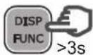
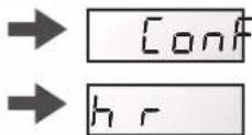
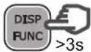
- Press and hold DISP/FUNC for 3 seconds. All three LEDs will blink
- The screen will display "ConF" and then "hr"
- Press DISP/FUNC to show the time on the internal clock (hh-min)
- Press the up / down buttons to adjust the hours / minutes
- Press RUN/STOP to exit and save
The display will show the current speed or StoP


Note: Adjusting the time on the internal clock is important in Timer mode. It will remain saved if the pump is switched off.
4.2 Setting the priming phase


Note: If the priming time is set to zero the screen will display "ProFF": priming has been deactivated


USE ONLY HAYWARD
Genuine REPLACEMENT PARTS
4.3 Setting the Skimmer function
See section 2.2 for an introduction to this function
| Press and hold DISP/FUNC for three seconds
All three LEDs will blink and the screen will display "ConF" | DISP
FUNC >3s | → | Conf
V1 V2 V3 |
| Press DISP/FUNC repeatedly until 'SFO.15' is displayed on screen: this is the default Skimmer time (in minutes) | DISP
FUNC x n | → | SFQ.15 |
| Press the up / down buttons to set the desired value (0 to 30 minutes) | | → | SF020 |
| Press DISP/FUNC: the screen will display "St 1hr" - this is the default Skimmer cycle period | DISP
FUNC | → | St 1h |
| Press the up / down buttons to set the Skimmer cycle period to 1hr, 2hrs or 3hrs | | → | St 2h |
| Press DISP/FUNC: the screen will display "S2800" - this is the default speed of the Skimmer function (rpm) | DISP
FUNC | → | S2800 |
| Press the up/down buttons to display the desired speed (600 to 3000 rpm) | | → | S2680 |
| Press RUN/STOP to exit and save The display will show the current speed or StoP | RUN
STOP | → | 1640 | StoP |
| Note: To deactivate the Skimmer and set the time to zero - display reads "SFOFF" | → | SF0FFF000 |
4.4 Restoring the settings
To restore the default settings and erase the Timer mode settings, do the following:
| • Press and hold DISP/FUNC for three seconds
All three LEDs will blink and the screen will display "ConF" | DISP
FUNC >3s | → [on]
V1 V2 V3 |
| • Press DISP/FUNC repeatedly until the screen displays the message 'Init' | DISP
FUNC x n | → [n]
[1] |
| • Press and hold the 'up' button for 3 seconds. The screen will read "donE" once the reset is complete | >3s | → [don]
[0] |
Reminder: default settings and their value ranges
| Priming Speed | preset buttons Skimmer fu | action Timer function | |
| Pr | ... | V1 V2 | V3 | | 5F 5 | 5... | E0 | E1 | E5 | |
| Units | s | rpm | rpm | rpm | rpm | min | h | rpm | hh-min | rpm | hh-min | rpm |
| Default | 240 | 3000 | 1500 | 2400 | 3000 | 15 | 1 | 2800 | 06-00 | 2400 | aFF | 0 |
| Mini | 0 (aFF) | 600 | 600 | 600 | 600 | 0 (aFF) | 1 ... | 600 | 00-00 | — | 00-00 | 0/600 |
| Maxi | 300 | 3000 | 3000 | 3000 | 3000 | 30 | ... 3 | 3000 | 24-00 | — | 24-00 | 3000 |
USE ONLY HAYWARD
Genuine REPLACEMENT PARTS
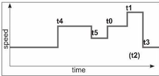
4.5 Setting the Timer mode
The control panel allows you to program multiple sequences (see section 2.3) or Timers t0 to t5, which do not need to follow chronological order.
Unused Timer settings will be deactivated.
Timer 't0' can be set to 00:00, 06:00 (by default), 12:00 or 18:00. It cannot be deactivated.
You cannot adjust the speed of t0, it is set at 2400 rpm
- Identify the speed profile you would like to program. The image opposite is shown as an example.
- Check whether the internal clock has been set correctly.
| Press and hold DISP/FUNC for 3 seconds
All 3 LEDs will blink and the screen will display "ConF" | DISP
FUNC >3s | → conf
V1 V2 V3 |
| Press DISP/FUNC twice and the screen will display "t0" | DISP
FUNC x 2 | → t0 |
| Press DISP/FUNC: the screen will display "06-00" - this is the default value of t0 | DISP
FUNC | → 06-00 |
| Press the up / down buttons to set the value you would like for t0 (00-00, 06-00, 12-00 or 18-00) | | → 18-00 |
| Press DISP/FUNC: the screen will display "t1oFF" | DISP
FUNC | → t1oFF |
| To activate this Timer setting (as an example), press the 'up' button. The screen will display "t1 on" | | → t1 on |
| Press DISP/FUNC: the screen will display "00-00" | DISP
FUNC | → 00-00 |
| Press the up / down buttons to set the desired timetable (hh-mm) | | → 20-00 20-45 → |
| Press DISP/FUNC: the screen will display "0" | DISP
FUNC | → 0 |
| Press the up / down buttons to display the desired speed (600 to 3000 rpm or 0) | | → 2740 |
| To go to the next Timer setting, press DISP/FUNC: the screen will display "t2off". In this example the Timer setting stays deactivated | DISP
FUNC | → t2off |
| Press DISP/FUNC to go to the next Timer setting and repeat the steps (activation, timetable, Timer setting and speed) | DISP
FUNC | → t3oFF etc ... |
| Press RUN/STOP to exit and save
The display will show the current speed or StoP | RUN
STOP | → 1640/ StoP |
USE ONLY HAYWARD
Genuine REPLACEMENT PARTS
5. DISPLAYING CURRENT SETTINGS
Note: The pump must be switched on, either running (post priming phase) or stopped.
To display the current settings, press DISP/FUNC.
If no button is pressed for 15 seconds thereafter, the display will go back to normal (showing the current speed or Stop).
| • Press DISP/FUNC: the screen will display "hr"
Press again: the screen will display the internal clock time | DISP FUNC→ hr 11+4 DISP FUNC→ |
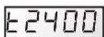
| • Press DISP/FUNC: the screen will display "t0"
Press again: the screen will display the 0t timetable (the t0 speed is fixed at 2400 rpm) | DISP FUNC→ to 12+4 DISP FUNC→ |
| • Press DISP/FUNC: the screen will display "t1"
Press again: the screen will display its timetable (hh-mm) | DISP FUNC→ to 109+4 DISP FUNC→ |
| • Press DISP/FUNC: the screen will display the speed of the Timer setting (in rpm) | DISP FUNC→ 1240 |
| • Press DISP/FUNC: the screen will display the next Timer setting, the timetable and the speed - you can do this up to Timer setting 't5'
Note: Deactivated Timer settings are not displayed | DISP FUNC→ to 2 etc ... |
| • Press DISP/FUNC: the screen will display "P- - - " Power consumption (in Watts, a value of +/- 10%)
Note: P = 0 W when the pump is off. | DISP FUNC→ P 634/ P 0 |
| • Press DISP/FUNC: the screen will display "h - - - " The pump's operating hours counter
Note: The counter runs up to 9999 hours | DISP FUNC→ H2857 |
| • Press DISP/FUNC: the screen will display "----" Total energy consumption (in kWh)
Note: The counter runs up to 99999 kWh | DISP FUNC→ 06542 |
| • Press DISP/FUNC: the screen will display "- - - " Partial energy consumption (in kWh) since the last reset | DISP FUNC→ 00086 |
| • To reset the partial energy consumption counter:
Press and hold either of the up / down buttons for 3 seconds.
The message "CLEAR" will be displayed, indicating that the counter has been reset to zero. | → CLEAR |
| • Press DISP/FUNC: The screen will display "SF On" or "SFOFF" to indicate that the Skimmer is on or off | DISP FUNC→ SF ON/ SFOFF |
| • Press DISP/FUNC: Screen displays "t - " This is the temperature of the power module (in °C) | DISP FUNC→ T 74 |
| • Press DISP/FUNC to exit back to the normal screen (showing current speed or Stop) | DISP FUNC→ / STOP 1640
E2400/ E5stop |
USE ONLY HAYWARD
GENUINE REPLACEMENT PARTS
MAINTENANCE
- Completely disconnect the pump from the mains power supply before opening the cover and cleaning the strainer. Clean the strainer basket regularly. Do not bang on the basket to clean it. Check the seal on the cover of the strainer and replace it if necessary.
- The motor shaft is mounted on self-lubricating bearings which do not require any subsequent lubrication.
- Keep the motor clean and dry and ensure the ventilation openings are not blocked.
- The mechanical seal occasionally starts to leak and must then be changed.
- Apart from cleaning the pool, all repairs, servicing and maintenance must be carried out by a Hayward®-approved agent or a qualified person.
Wear parts of the pump mentioned below should be maintained according to their estimated life:
Wear parts estimated life
Mechanical seal 2 years or 10.000 hours.
Motor bearings kit 2 years or 10.000 hours.
Set of gasket (strainer, housing, bulkheads, drain) 2 years or 25.000 hours.
Capacitor
2 years or 10.000
WINTERING
-
Empty the pump by removing all the drain plugs and store them in the strainer basket.
-
Disconnect the pump, remove the pipe connectors and store the entire unit in a dry, well-ventilated place or at least take the following precaution: disconnect the pump, remove the 4 bolts attaching the pump housing to the motor bracket and store the unit in a dry, well-ventilated place. Then cover the pump housing and strainer to protect them.
N.B.: Before recommissioning the pump, clean all the internal parts to remove dust, lime scale etc.
TROUBLESHOOTING
A) The motor does not start
- Check the electrical connections, switches or relays, and the circuit breaker or fuses.
- Ensure that the motor turns freely by hand.
- Check that rotation speeds V1, V2 and V3 are not programmed at 0rpm. If they are, restore the factory settings (see section 4.4).
- If the screen displays any of the error messages below, please contact your vendor:

Constant low line voltage

Constant high line voltage

Power module overheating

Motor overheating

Overload

Internal problem with electrical supply

Starting problems

Internal short-circuiting problem

Multiple problems

Communication problem

Refer to page 21
B) The motor stops, check
- The cables, connections, relays etc.
- Voltage drop on motor (frequently caused by cables that are too small).
- That there is no seizing or overheating (by reading the absorbed current).
N.B.: The motor on your pump is fitted with a thermal protection which, in the case of overload, will automatically cut the circuit and avoid the motor being damaged. This triggering is caused by abnormal usage conditions which need to be checked and corrected. The motor will restart without any intervention as soon as normal operating conditions are restored.
C) "OLOAD" appears on the display (overload or over-heating problem)
- Check that the motor shaft turns freely
- Check that no debris is preventing the turbine from rotating freely
- Check that the motor is correctly ventilated
- After correcting the problem, press the On/Off button
USE ONLY HAYWARD
Genuine REPLACEMENT PARTS
D) The pump does not prime
- Ensure the strainer housing is filled with water, that the cover seal is clean and correctly positioned and that no air can enter. If necessary, tighten the cover lock screws.
- Ensure that all the suction and discharge valves are open and not blocked and that the suction outlets in the pool are fully submerged.
- Check that the pump draws by freeing the suction as close as possible to the pump:
a) if the pump does not draw despite being sufficiently full of priming water
- Tighten the bolts and pipe accessories on the suction side.
- Check the voltage to ensure that the pump is rotating at the correct speed.
- Open the pump and check that nothing is blocking it inside,
- Set a priming speed that is fast enough
- Clean the filter and try again
- Replace the mechanical shutter.
b) Try priming in re-circulation mode. If the pump is drawing normally, check the suction pipe and strainer which may be blocked or be allowing air to enter.
- That no air is entering the suction side and causing dull crackling in the pump.
- That there is no cavitation caused by insufficient diameter or a restriction in the suction tube. An over-sized discharge pipe can also cause cavitation. Use pipes of the correct size or purge the pipes if necessary.
- That no vibration is occurring due to incorrect fitting.
- That there are no foreign bodies in the pump housing.
- That the motor bearings have not seized due to excessive clearance, rust or prolonged overheating.
USE ONLY HAYWARD
Genuine REPLACEMENT PARTS

BOMBA CENTRÍFUGA DE VELOCIDAD VARIABLE
MANUAL DEL USUARIO
CONSERVE ESTE MANUAL PARA CONSULTARLO POSTERIORMENTE

HAYWARD


Dispositions necessities:
4.5 Programming at timetilstand
MAHDOLLISET VIAT JA RATKAISUT
CEHTPOBEXKbI HACOC C PEGYINPYEMOCKOPOCTbIO
PYKOBODCTBO NO 3KCNJYATAUIN
COXPAHЯITE DAHHOE PYKOBODCTBOДЯ DAJIbHEIShERO IcNoJIb3OBAHNIA

HAYWARD


IPEyPExEHE: OnacHocTb nopaxeHn 3JIekTpOToKOM. Heco6JIHOdeHne nHcTppyKzM MoXeT IpeCTaBnTb cepbe3HyIO onaCHOctb dJa Xn3HN. IJRA nCNoJIb3OBaHnB INaBaTeNbHbIX 6aCCeHax
I PEPYIPPEKJDEHNE - Ipeo OTKpbBaHnem KpbIaKn fNbTpa dno ONUCTKN NOJIHOCTbIO OTCoeHNHTe HAcOC OT CTeBORO NCTOHHKA NITAHNA.
ПРЕДУПЕЖЕНЕ -ДЛЯ ПОФЕCCNHOJIБHOTOICNOЛБ3OBAHNY - Bce 3ЛeКТпчecкп NOДСоЕДИЕнгьВилJOHЯOTСКBAJIINФИЦЮВАнHBIM 3ЛeKТрИКOM B COOTBETCTBIM C MecTHbIMN CTaHДapTAMN NO 3ЛeKТрИЧEcTBY IJIN, B npOTNBHom cIyuee, МжdyHapOdHbI CTaHДapT IEC 60364-7-702.
I PEPYIPEXJEHNE - CneTe 3a TeM, YTO6bI OOBpyOBAHHe NOKIOUcOcB TOnbKO K PO3eTKe 230V c 3aUNToIOT KOPOTKORO 3aMbKaHn. INaHHe K HAcOCy NOaETCaPdEnITeNbHbIM TpaHcFOpMaTOPOM NIN Yepe3 yCTpOCTBO OCTaTOHOro TOKA C HOMHaJIbHbIM OCTaTOHbIM pa6OUM TOKOM He 60Jee 30 mA.
I PEPYPEXEHNIE -EtN DONKHb HAXOHTC NOI pncmOTpOM,TO6bI OHn He MOrn IrgpaTb C obOpydoaHem. He nOHOcHTe K OTBepCTnM IN DBNXUYIMCRACTrnn PabCbI NocToPOHHne PpeMetbl.
PENyPENKDEHNE- BnraTeB Tpe6yeTcKa KcCneyET 3aEMnIb. POKNIOHTe NPOBOd 3a3emHeHnK 3eHOMy 60NTy, a c np6oPamn, nOKnIOUeHHbIMn IPOBOOM, INoONb3yIte COOTBETCTBYUOYu BNKy C 3a3emHeHnEM.
PENyPExKHeHNE - Pn noKnHueHn DnBraTeJRA K dpym M c 3aemHnem nCNOb3yte yctpoCTBO 3aemHeHn DnRaTeJn npoBOD ceeyHn, COOTBeTCTByIOUe IpaBnAM nNoIb3OBAHn 3JIeKTPonpnpam.
I PEPYPEXKDEHNE -Pn3eKTPoONKJIOUeHNm CM. dNarpaMMy Ha 7INbDnke NOKJIeMMHO Kopo6ko JDBuratJe. Ipeed noaey nntAHy y6eHTecb, YTO BCE COeHNHeHry BblONHeHb IIOTHO N H3OJNPOBaHb.Ipeed noaey nntAHy BepHNTe Ha MeCTO BCE KpbIshk.
PENyPENKDEHNE -Y6eINTEcB, YTO HAnpJxHHe NDBIRATEIaCOOTBeTCTByET HAnpJxHIO BAWeN 3JNeKTPOCeTN, a 3JIeKtpoKa6eJIu COOTBeTCTBYOT BONbTaKy I TOKHaCoca.
I PEPYPEXJEHNE - IpoHTaTe BCE INHCTpyKuB B DaHHOM PYKOBOCTBe NOJIb3OBaTeJn Ha O6OpydoBaHN. Heco6JIIOHeH INHCTpyKuM MoKET npINBeCTN K TpaBMAM NII NOBpeXDeHnM. HactOaUdOKyMeHT npeJaEtCBAeBcy 6acceHa, n BnaJeue o6raH coxpaHrTa daHHbI DOkymeHT B 6e3Onachom MecTe.
I PEPYPEXJEHNE - IcnoJb3OBaHne, YCTKa, OcbnyKbAHne yctpoCTBa DetbM CTapwe BOCbM NET INI JIaMHe, He ObaIaIOUIMN DOCTaTOUHbIMN 3HaHnAIMN ONbITOM, IuCaMn C ORpaHueHHbIMN OIN3NuCeckmM, CEHCOPbIMN INIYMCTBeHHbIMN CNOCO6HOCTaMn BO3MOXHO TObKO NocNE COOTBcTCTByIOUero INHCTpykTAka N NOd HAdNeKaUIM INPcMoTpOM B3pOcNOrO OTBeTCTBeHHoro YeNoBeka, YTObI ObecNeHTb Be3OnaChyIO kCpIyaTaUIO yCTpoiCTBa, a TAKKe IOHMaHne n I36eKaHne OnaCHOteN, CBraaHHbx C erO 3KcPiyaTaUae.
35°C.
I PEPENPPEKDEHNE - IcnoB3yTe ToIbko opnHaNbHbIe 3aunactn KOMnaHm «Hayward》.
I PEPYIPKDEHNE - Ecnn Hyp nHTaHn NOBpeXdeH, TO BO n36eXaHne npaxeHn 3NeKTPueckm TOKOM 3aMeHrBo ero MOxET NnB pOnn3BOuNTeNb, cepBnCHbI aReHT nn CneuaJIbHO 06yehHb TeXHk.
PENyPExHNE - OToCoeHHeNn OTeBoro NcToHnKa NtAHn B CTAHOHaHyO 3NeKtpoPoBOky BCTpaBaTcB HeHN BbIKNoTaTeB C 3aOpom MeJy pa3OMKHyTbIMN KOHTaTAMn Ha BCEX NOJIocax, KOTOpbl ObecneuBaET NoHoe OTcoEINHeHne npnpeHapxKeHm III KaTEROpn B COOTBeTCTBn C npabnAmn no npoBoDke.
I PEPYPEXKDEHNE-3anpeaetc3KcNpyatnpoBt haococ nnnabatebHO 6accen,ecnnoBpeXdeHbCNILOBOKabeHn KOpnyc coeHHtebHO Kopo6Kn 3neKtpoDBrataJI. 3TO MOKeT npBecTN K npaaKeHNO 3NeKtpueckIM TOKOM.IOBpeXdeHHbe wHyp nTTAHn Hn COeHHtebHna Kopo6Ka 3neKtpoDBrataJI DOJNXb6bl 3ameHeHb CepBnCHbIM aERHTOM nHn aHaIOnuHbIM KBaHPhiunpoBaHHbIM CneuaJIInCTOm cpa3y Jx BO n36exaHHe C8raHHbx Yrpo3.
PENyPExEHN - 3neKtpoBnraTeB dIg 6accHna He Ochauen npedoxpAHnTebHO BakyMHO CNTeMOI (SVRS).CnCTema SVRS nomoraetnpodTbaaTa 3aTOnnHe H3-3a HaxOxHeHr TeHa HoBnBOHbIX CNIBOB. B HeKOTopbix 6accHnx npi nonaHaHm TeJa YeNoBeka Ha CInB, yeNoBek MoKeT Nonactb B NOByuKy n3-3a BCacBaHn. B 3aBNCIMOCn OT KOHpyaun 6accHna MoKeT NtpeboBaTcY yCTaHOBka 3aUnTHOH BakyMHO CNTeMb I COOTBeTCTBN C MeCThBiIMN TpeBoBaHnMI.
PDEUYPEXKDEHNE - 3TOHACOC COeepknt 6aTaepo, c KOtopo no coo6paXeHnM 6e0nacHOCTn IIO6bIe MaHInyJIaCIN DOJXhBI BbIOJNHTbcra ABTOPI3OBaHHO TExNHueCKO cnYK6oB.
NcnoJIb3yIe TOJIbKO OPINHAlbHbIE 3ANCTN KOMNAHNI «HAYWARD
8
I03dpabJem! Bby ToJIbKO UTO npIO6peJH HAcOC C peryINpyeMOCKOpocTbO KOMnAHy Hayward
HacocbI c perynpyemoi ckopocbIO kOMnAHm Hayward 念 ochauehbl DBnraTeeM C NOCTOHHbIM MaHHTOM m3neKTPOHHO KOMmyTaueH nepeM. ToKa nocJeHrero nokoneHry. YnpabHeHne daHHbIM DBnraTeeM OcyuecTBJREt MKNpOnpoecCop, NoDKlueyHHbIK perynTopy yacToBtI, noDnepXnBaHoueMy cNeyUoune XapaKTepNCtIKN:
- OTo6paXeHHe cKOpocTn BpaUeHnHa KOHTpOJbHOM 3KpaHc
- PpOu3BOUInTeIeM npEynCMOTpeHbI 3 ckOpocTn BpaueHna (KHOIN V1, V2, V3), KOtOpBle MOrY T HAcTpAnBaTbcr NOJIb3OBaTEIeM
CnCTeMaTHuecka 3aINBka npN KaKdOM 3aYcKe, CKOpOCTb IN npoDoJIKNTeJbHOCTb 3aINBKn RABJIOTcHAcTpaINBaembIMN
-ФунклгСКИММЕРа,СНЯТп ВЕХHERO CLOY BOДы
- Pporpammpyemar yHKun TaMepa
- OTo6paKeHHe MrHOBeHHHO Ntpe6JIaEmoM MoUHOCTn
- OTo6paXeHne o6uero ndoJeBoro 3HepronoTpe6JeHn
- OTo6paXeHHe BpeMeHn pa6Otbl Haocca
Hn3Km 3ByKOBoy yPOBeHb
KoHCTpykuOHbI cTaNapt TEFC IP55
YcTaHOBnTb HAcOC Ha IOCTaTOHOM pACCTOHN OT 6accHeHa DnA MINHM3aCn CB3N MeKdy CnCTeMoN acnnpaunn HAcOCOM C cJIbIO ORpaHnueHn IOTepb Ha npa3HTyHO Harpy3ky Upe3MePbIX IOTepb B rIpaBnueckom KOHType.
PnTOM Heo6xOIMO CTpOro Co6IIOaTb pacCToHHe, PpeyCMOTpeHHoe DeiCtByUcIMN HopMaMn yCTaHOBKn IIO6HO 06OpdyOBAHn (MNHNm3.5 M). YcTaHOBkA NcNoJIb3OBAHne npOyKTA Ha Bbcote MeHee 2000 M.
YcTaHOBnTB HACOC B npOBETPnBaEMOM CYXOM MecTe; IJI ECTeCTBeHHoB BeHTnIaIyI IN DBnIaTeJIH HeO6xOdmo ObecneuHb
CBO6OHyu CHPKyIaHIO BO3dyxa BOKpyr HrO. OBeCneBte CBO6oHoe npocTpaHCTBO Ha pacCToHm 0,5 M BOKpyr Hacoca Heo5xOIMo nepnoDnueckn npOBepaTb, YTO OxJaXeHNIO DBrIaTeJIa He npenTCTByOT KaKe-JIn6o ObBeKTbl, JInCTbI INpOuyne npedMeTbI.
MoHTax Hacoca DoJKeH OcyueCTBnTbCra TaKIM o6pa3OM, YTO6bl BHeUHN ABTomaT, BCTpoeHHbI B CtaUHOapHbI 6NOK, 6blXopoO WnEHN IeKO DoCTyNeH. AToMAt DoJKeH HxOOnTbCra PRAOM C HAcOCOM.
Hacoc doJkeh yctHaBnBaTbCra Ha cTaunHOapHoe 6eTOHHoe ochoBaHne npn NOMOHN HATXHBIX 6oTOB dIg 6eToHa 8 MM, 3aBnHnBaEMbIX B pndyCMOTpeHHie MOHTXHbIE OTBepCTN. Bo n36ekAHNE ocna6neHn 3aTAKKn HATXHBIX 6oTOB C TeueHnEM BpemeHN Heo6xOIMNO pndyCMOTpeTB CTOnOpHbIE WaIbI. PnH Heo6xOIMOCtN MOHTaKa HACoca Ha DepeBHHOM NOny MCIOJIb3OBAb BVHTb I Dn DEpeBa C WcETNRpaHHo rONOBKO 8 MM, a TAKKe CTOnOpHbIE WaIb6a, npenrTCTByIOune ocna6neHn 3aTAKKK C TeueHnEM BpemeHN.
YCTAHOBNTb HACOC B 3aunuHem MecTe BO n36eKaHne nonaHaHa Ha 6Iok ynpabHeHn cTpy BoDbl.
YpOBeHb 3BykoBOrO daBnEHHaCocOB kOMnaHm Hayward COCTaBnIeT MeHee 70 dE A.
Yka3aHn, NOIeXaJIe BeBIOJIHeHnIO:
BbInonHnTb 3a3eMJIeHne Hacoca: 3anpeHeHO BKJIIOuTaB He3a3eMJIeHHbI HACOC.
- Подкночь haoc поюи kaбеля Tuna H07RN-F 3G1,5mm².
- Ipeycmpte3aunTHoe yctpoCTBO NO dHcpeHuaNBHOmy TOK 30 mA, npHa3NaueHHoe n3aunTbIIOJe ot Nopaxehn3Jektpnueckm TOKOM No npuHne HapyuHn3Jektpnuecko nO3OJIuN6obopyoBaHn.
- PpeDyCMOTpeTb 3aUHTy OT KOPOTKx 3aMbIKAHNI (HOMHAn ONpeDEJIeTcB 3aBUNMOCTN OT 3HaueHNI, INPBeDeHHbIX Ha cnnpMeHHoT TaBnue Ke Dniratela).
- IpeyCMOTpeb yctpoCTBO OTKJIIOUeHnO T cETN NNTAHn C MEKKoHTaKTHbIM paccToHnEM (INBCEX NOHOCOB), oecneuBaIOUM NoIHOe pa3MbKaHHe B ycNoBx 3-ⅰ KaterOpn nepeHaPraKeHn.
BHIMAHHE: Nocne noHoro OTKIOueHn HaOcOa OT 3IeKTPoCeTn NOIOXdaTb He MeHee 5 MmHT nepeI npOBeHnem Onpaun H aBnIATENe IIN paCpEeNITeBHO KOp6Ke: OnacHOCT b nopaxeHn 3IeKTPOTOKOM C BO3MOxHBIM CMePTeHBIM NCXODOM.
Iy3eKpOdBnraTeJe, KOtOpbIMN OCHaSeHb HAsn HAcocB, PpeDyCMOTpeHa TepMuecka 3aunTa, cpa6aTbBaIOuaq npnepepy3kax IIN nepepeBe 6MOtKN DnBnraTeJI. DaHHa 3aunTa pON3BOoNT BO3BpAT CNTEmbl B INCXODHOE COCTOHNIE NOCNE CHIXKeHnA TemnepaTypbl 6MOtKn.
B COOTBECTBm C Tpe6oBAHnMn 3aKOHOaTeJIbCTBa He3aBNCIMO OT NcONb3yEMORO TINa DBIraTeJN NOMMO BblJepeHcJIeHHbIX yCTpoIcTB Heo6xODIMO IpeDyCMOTpeTb TepMOMaHHTHyU 3aUHTy, OTKaJIb6pOBaHHU B COOTBeTCTBm CO 3HaueHnMn Ha cnPmeHHo TaBNIuKe DBrATeJIa.
B Ta5nue Ha cTq. 169 npBedeHb pa3nHbIe XapaKepncTNKn DBnraTeJI, KOToPbIM Ochaanotc HauHn Hacocbl. NCNoJIb3yUte TOJbKO OPnIHANbHbIe 3AnqACTN KOMNAHN «HAYWARD

HAYWARD
IopKIOeHne K cetn 3eKtponntAHn: Y6eINbC, YTO HanpRaeHne nHTaHn, TpeSyemoe dIra pa6Obl DnIgATEJI, COOTBETCTBYET HAnpRaeHnO CTeN, NTO CEHeHne I DNHa SHypa nTahn COOTBETCTBYOT MOUHOCTN IN CNIE TOKA HAcoca.
Bo n36ekahne onacbix cntyaunBce 3nEeKtponodkIouehna Hacoca, a TAKKe BHeceHne N3MeHeHn B uHyp nHTaHn DOJKeH BbINHrTB KBaInDnupOBaHHb CneuaJIunct.
IyBbINONHeH3JKeTPONoKIOUeHn Heo6xOIMo Co6NIOaTB MapKnipOBky, yKa3aHHyIO IOd COeHNHTeNbHbIMN KJIEMMaM.
TtateIbHn npOBepntb KaueCTBO 3aTgKnn I repMeTuHOCb 3JeKtpuHecknx CoeHHeHn Ipeed noDaay HapJxKeHn nItaHn.
Ctporo co6nOaTb nocJeDoBaTeBnOCTb npokIaKn Ka6eJy Ope3 OTBepCTne I cneuaNbHO npedcMOTpeHbI
MaHHTOUN3JIeKTPNK; npn 3TOM caJIbHnK oEecneuHbaet repMeTuHocTB BOKpyr KaBeIa, a MaHHToDn3JIeKTPNK, npedctabJraTe coboi qInbTp dnn 3JIeKTPomarHHThBIX NOMEX.
BpeMeHny npEeBapnteIbHyKabeBHy npOBoIky, KOtOp0 ocHaIeHbI HeKOToPbIe Haun Hacocbl, Heo6xoIMMo ydaNtB npn OKOHaTeJIbHOM NOKJIIOUeHN HAcoca K nCTOuHNy PNTAHNA. Ha cAmOM DeJe DaHHOe npEeBapnteIbHoe o6OpyIOBaHne NCNoIb3yETcA NCKIOUHTeJIbHO DnI npOBedeHNA 3aBOIDCKNX IcNbITAHNI HA 3Tane n3rTOBJIeHN.
YCTAHOBKA
YctaHOHTb HAcoc dJa 6accseHa, MakcImaIbHo OOrpaHnivB noteepn Harpy3Kn C co6NIODeHem MInHIMaJIbHorO paCtOraHnB 3,5 M OTHeceHnHa HAcoc aOT 6accSeHa B COOTBeTCTBm CO cTaHaprTom NO MOHTaxy. AcnpaOnHHb TpyoONpOBoDdoJIkeH yCTaHaBIMBaTbCc He60JIbShM BOCXODJUHMM HAKIOHOM OTHCINTEJBHO OCN HAcoca. Y6eITbcA, YTO BCE NaTPy6K NAtaTeNbHO 3aTMyTbI INrePMeTNUHbI.
B IIO6OM CNYuae, He IOnyckaTb Upe3MepHO 3aTJxKn DaHHbx Tpy6oNpOBOOB. Ppi IcIIONb3OBAHm INaCTIKOBbIX MaTePnaNoB Dnno obeceueHnre repMeTHUHOCTMOXHO IcNOb3OBAbT NCKIOHTeHbTOePHo. AcnIPAQUHOHAR Tpy6a DoTKHa IMeTB BoJIbShn INn no KpaIHe Mepe TaKo JKe DNAMTp, KaK n OTBoHnA. N36eratb BIAkHbIX MecT C IIOXoB BeHTINrAChE. Ipn OXIAKDeHn DBIrataTeHn HEo6XODMa CBO6OHa HApKyIaIaBn BOxDyxa BOKpyr Hero. YcTaHOBt HAcOC B 3aunIeHHOM MecTe BO I36eKaHne IonoDAHn Ha 6Iok ynpabNeHn cTpy BObl.
BAKHO: PpOBepuHnPaBHeHne BpaueHnpepeOKoHuaTeNbHbIM NIOKIIHOeHnem DnBraTeJIa.
YKA3AHNIO 3ANYCKU IN BXOUY B PABOCHI ZMKJI: 3aONHnTb KOpNc npePnIbtpa BOoD IO ypOBH aCINPAuHOHOTpy6bl. 3anpeheo 3anyckatb HACOC 6e3 BObl, OHa HeoXoUMdaONxOJAAKeHnry n CMA3KN MEXAHueCKORO 3aTBOPa. OTKpbITB BCE Klanahb acnpauOnHHbIX N OTBOhBX TpyobnpoDBO, a TAKKE Knaanah CTpaBnBaHnR BO3dyxa n3 fInltpa, eCN TAKOBI npedymotpeH. (Heo6xoIMNO ONHOCTbU ydAnTb BO3dyux n3 acnpauOnHHbx TpyobnpoDBO.) 3anyCTNTb arperAT nnoOkdAteb HEKOTope Bpemrdo BVODa B pa6ouy niKNI. PtBtMnHT He cHTaETCR CNLkOM BoJIshm INTEPBALOM BpemeHN DnRA BXODa B pa6ouy nIKN (npoeCC BxOaB pa6ouy nIKN 3aBNCIT OT BBICOTb acnpauOnHOH CNTEmbl n DnHb aCINPAuHOHOT py6bl). Ecn HAcOC He 3anyckaetc nnHE BXOITB PA6OUH nIKN, CM. pkyoBOcTBO NO NONCKY uYCTPaHEHIO HEICnPABHOCTeN.
2. PEXKIMbI PABOTbI HACOCA
2.1 Puchon pexnM
B PyHOM pEXKMe, B 3aBnCIMOCTN OT nCNoJIb3OBAHnI 6acCeHa, nOJIb3OBaTeNb BpyHyIO 3aNyCKaET INN OCTaHaBJIuBaET HaOC.
3aynck HacocnpeboNT ero B COCTOHN 3aINBKn (a). DaHHoe coCTOHN JBNETCn HAcTpaNBAEMbIM (CKOPoCTb IN npoONKInTeHbOcTB, § 4.2). 3aINBky MOxHO OCTaHOBTb npn 3anycke (S 3.2) nJn OTKnIOuHTb HAcTpoNkax.
- 3aTeM CKOpOCTb CTA6HnH3NpUyETcdo NoctoHHoro 3HaueHnra (b) (no yMonuHaHnIO do CKOpocTn V2). DaHHaer CKOpocTb MoKet Bbl6upatbcn Y cTaHaBnBaTbcn NOIb30BaTeHem ( § 3.3).
-Поссе octaHOBa/новtopHOrO 3anycka Hacoc Cta6nIn3npyeTcRdo nocJIeDHe 3anOMHeHHo CKOpOCTN.
2.2 Ckmmep
ФункцяСкIMМераNo3BOJЯТСИМATbВePxHnCNoB0dIu 136ExKaTb HAKONJIeHnA, a TAKKe 3aCToR 3aRpy3HeHn Ha nobepxHOCTN 6acceHa.
-Даннaya Функцяягьяется abTomatuecko: Hacoc pa6oTaet Ha NOBblIeHHOc CKOpOCTn (c), B COOTBetCTBm C yCTaHOBJIeHHbIMN BpeMeHem nUKNOM.
Bhe pa60bHa noBbIeHHoCkOPOCTn, HAcOC BbIXOHT Ha HOMHAnbHyIO CKOpOCTb, KaK npu ynpabJeHN B PyHOM pexKIMe, TAK u B peXmE TaMepa.
ΦyHKUa CkMMepa MoKet 6bItb OTKnHueHa (CM. HAcTpOuKn § 4.3).
2.3 Pekum TaMepa
Bpekmte Taumepa pa6oTa hacoca kpyrnoCytoHNO (24/24) aBTOMATn3nPOBaHa. NpIb3OBaTeJIb MoKET nporpaMMnpoBaTb pa3NHyIe IocJeIOBaTeJIbHOCTN BKNIOueHn cKOpOCTe (d). OHN bIBnPaOTcB 3aBNCIMOCtN OT yCTaHOBKn O6OpyIDOBaHn (peKIM HArpeBa, 3HeproScBeperaIoUe ee YCTpOInCTBO n T.D.) n rpaФnKa nCNoIb3OBaHn 6acceHa.
- Ecni yHKnra CkMMepa BkJIOueHa, OHa DObABTcB DaHbIe nocJeIOBaTeNbHOCTN BbINONHeHrynpaBnHOe npoPamMbI.
Hacoc MoKeT 6bItb octaHOBHe (noCTaBHeHa nay3y) B pexKMe TaMepa. Pn NOBtOpHOM 3aNyCkE CKOpOCTb 6yDet COOTBeCTBOBaTb TeKyueB b pexKMe TaMepa.
-Дпя поррамповаяразжima Таймера смOTрптse 4.5
2.4 Pbyar nepeKIOueHn MExy Pyhblm peKMOM/peKMOM TaMepa
CmeHa peKIma BbIIOJIHReTcR npn HaxKaTm Ha KhONKy MOEIOKA3aHO HIXe:
PuyHoi pexm Pexm TaMepa
OTo6paJxHHe cKOpocTn 6e3 npCTaBKn
Topaun CBeToDnOyKa3bIbAeTHaBb6paHHyIOCKOpocTb(V2NoymoJIuHaHIO)


OTo6paKeHne cKOpocTn C npCTaBkoI


CBeToOnObl He ropaT
NcnoJIb3yIe TOJIbKO OPINHAlbHbIE 3ANCTN KOMNAHNI «HAYWARD
8
2.5 PooknueHne BHeuHNx uΦpObBx BXoOB
BHIMAHHE!IIO6bIe 3NEKTPnueckne pa6oTbHa Hacoce BbINOJHrTe TOnbKO cnycTe 5 MmN nocne erO OTKnIOUHeHn OTOE
HnltpaunOHbHnacoc OCHaueH 5-npOBoHbIM 3-MeTPOBbIM Ka6eIem dnn CoeINHeHna Yetbipex UnppoBbIX BXoOB IN cyxNX KONTAKTOB 6e3 noteHuaJa (Pa3OMKHytoe/3amKHytoe).
PpIMepbI NcNoJIb3OBAHnI cIΦpOBbIX BXoIOB
- YctaHOBtCe CKOpOCTb n pacxO, KOtOpbI Tpe6yEtc IJIr HAdnEkaUe pa60Tb IepnΦepnHbIX yCTpOcTB, TAKNX KAK TEJIIOBOH HAcOC, OTKaTbIBaIOUmC RPOJIET NII HAHTeTaeMbHbI ABTOMAT N. D.
- YctahOBHTe Bbl3OB KOMaHd IINI NOJb3OBAteBckoro INHTeppeCa. DaHHbIe cHpOBBie BXoDbI No3BOJIOT ynpabTb Ha pacCToRHN Tpx MeTpOB cyHKUnei Run/Stop, a TAKKe TpeM CKOpocTMy (V1-V2-V3).
BO3MOXHbIE HENCnPABHOCTN IN CnOCObI INX YCTPAHEHNA
A)Дигагель He 3anyckaetcra
- PpOBepnB 3JIeKtpueckne NOkHIOUeHnA, AToMaTbI npeJe, a TAKKe nppepbBaTeJn IIN pJaBKnpe npdoXpaHntTeJN.
- BpyHyIO npOBepntb CBO6oHoe BpaueHne DnuratEnI.
- Y6eHITbC, UTO CKOpOCTn BpaUeHn V2 n V3 3anpOrpamMnpoBaHaHbI He Ha 0 o6./MnH., B npOTNBOM Cnyaee BBIOJIHTb BOCCTaHOBJHe 3aBOcKnx HAcTpoE (CM. § 4.4).
4.Пи NOЯВЛЕнHa 3KpaHe OJHOrO n3 HnXeYka3aHHbIX KOIOB OUn6Kn CBxNITcEb CO CneuaJIInCTOM NO yCTaHOBKe 6obopydOBaHnI:

HnHexHe HnpxKeHnO T3aDaHHoro ypOBH

IobbIeHne HApJxKeHnO T3aDaHHoro ypOBHr

Peperepe6noka nHTaHn

IpeperpeB DnBaTeTJI

Tok neperpuy3kn

Ipo6Jema BHytpenHero 3JeKtponTaHn

HeydaHbI 3aynck

BHyTpeneHHee KopoTkoTo 3aMbikaHn

HeckoJIbKO npo6JIeM

KOMMYHnKaUHOHHbIc60B

06paTnTeScbKCTpAnuCe 160
B)Дигателб octaHaBnBaTeTc npoBepntb
- Ka6eJIu, coeINHeHna, pene n np.
- NaideHne HnpanjxKeHna DnBiratene (3aactyIO no npuHHe CmNkOM cna6bIX ka6eien).
- OtcytCTBne 3aknnHbAHnna nn neperpy3kn (npOBepNB 3NaueHne nOTpe6nemrTOka).
IPNMEAHNE: DnurteB Baawero Hacoc ochaueh Tepmo3aunTo, KOtopa B cnyae neperpy3ky aTOMaHTueckn pa3omKnet eNB BO n36eXaHne NOBpeXdeHn Dnuratena. TaKoe cpaBaTaBHaHne Bb3BaHO HexapakTePbIMu ycNOBnMn 3Kcnpyatauinn, Heo6xOdImo npOBepntb npuHHb i yCTpaHnTB nx. Dnuratelb nepe3anyctntcra 6e3 npoBeHnKaKnx-1n60 onepaun o6cnjXBAHnnoCne BOCCTaHOBNeHn HOpMaJIbHbIX YcNOBm 3Kcnpyatauinn.
C) Ha dincnnee noBnEeTcA «OLOAD» (npo6Jema neperpy3kn nnnepepeBa)
- Y6eHtbcra, yTO BaI DnIraTeJI BpaaTaCc CBO6oH0
- Y6eINtbcra B OTCyTCTBn KaKnx-Im6 IppeIaTcBn CBO6OdHOMy BpaUeHHIO TypbHbI
HcnoJIb3yIe TOJIbKO OPINHAJIbHbIE 3ANCTN KOMNAHNI «HAYWARD
8
- Y6eHtbcB IOCTaTOUHO BENTnIaUN DBuTaTeJIa
- Nocne yctpaHEnn npo6nmbi HaxmTe KhoNkY 3anycka/oCTaHOba
D) Hacoc He BXoJrB pa6oun cukn
- Y6eHnTbc8, cyTo KOpNyc npEoHnTpa 3aONHe HbOo, a npoknaKa KpbIkw NcTa n pacnoToKeHa npaBnIbHO, npenrTcByra nonaHaHIO B3dyxa. PnH Heo6xOdMocTu nepe3aTMyb cTOnOpHbE BNHTbKpblkN.
- Y6eHtbcra, YTO BCE KlaanahbI acnnpauonHHbIX N OTBODhBX Tpy6oPBOOB OTKpbITbI HHe3acopehbl, a BCE acnnpauonHHbIe OTBepCTna 6aaccenHa HaxoJrTcnoBdo
- IpoBepntb, BblnoHnreT nHaoc BCacbIbAHne, pa36noknpoBaB acnPauohHOe OTBepCTne, paCNOJoxEHoe KaK MoXHo 6JIHXe K HaCOcy:
a) ecn Hacoc He BbIOJIHReT BCaCbIbAHne, HecmOTpHa DoCTaTOUHOe 3aONHeHne BOOДIBy BXOaB pa6oHn cIKn
- IpeepaHTb 60ntbI n Tpy6oPBOHbIe cHTnHc CO CTOPOHbI acnnpauuN.
- IpoBepntb HnnpjKeHne, YTo6bl y6eNtbcra, YTO HAcoc Bpaaaetcna Ho DoCTaTOHNO CKOpOCTN.
- OtkpbItb Hacoc n y6eHntbcra, TTO BHTn HeT 3acopa.
- YctaHOBInTe DoCTaTOHyIO CKOpOCTb 3aJIbKn
- OuHCTnTE ФиЛьТР И NOВТOPИTe onepaциIO
- 3aMeHntb MexaHnueckn 3aTbOp.
b) POnpo6yInTe BblOnHnTb 3aNnBky B pexKme peuipKyJauCn. Ppi HOpMaIbHom BCacBaHn HaocCa npOBepntb acnpauonHHb Tpy6oPBOoD n npeOuTp, KOtOpBc MOrTy 3acOpNTBCr NnB KOTOpBc MoKeT nonactb BO3dyx.
F) Hacoc n3daet wym, npOBepntb
- He npnbelo Jn nopaanhe nIi HaJIuHne Bo3dyxa B acnpaunOHn CnCTeMe K NOBJIeHIO Tnyxix yMOM B Hacoce.
- He npoicxodnt n pa3pbIB nOTOKA BCNEcCTBne HedeocTaTOHORO dnaMeTp a nn cykeHHa acnpauacnoHHoro Tpy60npoBOda. Kpome toro, npuHnOH noD6Horo pa3pbIBa nOTOKA MOKET cTatb cnUHKOM 60Jbwoi pa3Mep OTBODHO rtp60npoBOda. IcnoIb3yIte Tpy6bl COOTBeTCTByIOUX pa3MepOB INn pIn Heo6XoDMOCtN pOBEINTE INx npOdyBky.
3.He noBnIacb Nn Bn6pauny.Bbl3BaHHa HeKaueCTBeHHbIM MOHTaxOM.
- He nonaJI IN B KOpNc Hacoc a NoctopOHnI npEdmT.
- He npo30uio 3aknnHbAHne noDunnHkoB DnirteTBAe CnIuKOM 6oJbWoro 3a3opa, Koppo3m nn dntelho nepereba.
GUIDE TECHNIQUE DE LA POMPE - TECHNICAL GUIDE FOR THE PUMP - GUIA TECNICA PARA LA BOMBA - MANUAL TECNICO DA BOMBA - TECHNISCHE ANLEITUNG FÜR DIE PUMPE - TECHNISCHE GIDS VOOR DE POMP - GUIDA TECNICA PER LA POMPA - TEKNISK GUIDE FÜR PUMPEN - TEKNISK GUIDE TIL PUMPEN - TEKNISK VEILEDNING FOR PUMPEN - PUMPUN TEKNINEN OPAS - TEXHINUECKOE PYKOBODCTBO NO HACOCY
| Pompe Référencce moteur | Puisance nominale | Voltage Fréquence Nb de phases | Ampérage | Taille et réglage disjoncteur | Hauteur manométrique à débit=0 |
| Pump Motor reference Nominal power | | Voltage Frequency Number of phases | Amperage | Circuit breaker size and setting | Manometric head at flow = 0 |
| Bomba Referenccia motor | Potencia nominal | Voltaje Frecuencia Número de fases | Amperaje Tamaño y ajuste disyuntor | Tamanho e regulação do disjunto | Altura manométrica de caudal=0 |
| Bomba Referência do motor | Potência nominal | Tensão Freqência Número de fases | Amperagem | Tamanho e regulação do disjunto | Altura manométrica para caudal = 0 |
| Pumpe Motorreferenz | Nennleistung-saufnahme | Voltzahl Freqenz Phasenanzahl | Stromstärke | Grosse und Einstellung Sicherung | Druckhöhe bei Durchfluss=0 |
| Pomp Motorreferentie | Nominal vermogen | Spanning Frequentie Aantal fases | Stroomsterkte | Grootte en installing beveiligingssschakelaar | Opvoerhoogte bij doorstroming=0 |
| Pompa Riferimento motore | Potenza nominale | Voltaggio FreqenzaNumero fasi | Amperaggio | Dimensione e regolazione interruptere differenziale | Altezza manometrica a capacità=0 |
| Pump Motors referens Märkeffekt | | Spänning Frekvens Ant. faser | Strömstyrka | Brytarens storlek och justering | Manometrisk uppforderingshöjd vid flöde = 0 |
| Pumpe Motor reference Nominal effekt | | Spending Frekvens Ant. faser | Stromstyrke | Størelse og indstilling af kontakt | Dynamisk løftehøjde med flow =0 |
| Pumpe | Referanse motor Merkeffekt | Spenning Frekvens Antall faser | Stromstyrke | Størelse og innstilling skilbryter | Manometrisk hóyle med ytele=0 |
| Pumppu | Vile moottori Nimei isteho | Jännite Taajius Valiheiden lukumäärä | Ampeerit | Katkaisimen koko ja sääö | Dynaaminen paine virtaamalla=0 |
| Hacoc | Aptikun dieitratène | Homin. noprr. Moiustoctb | Handjeckene Chactota Koll-bo phaz | Cina taoka | Manometriničeká blycotà prn paçxode=0 |
| SP3216VSTD | SPX1100SFVSTD(SB) | 1100 W | 220-240V1 50 Hz 1 Phase | 5.9 A | 19 M |
| SP3220VSTD | SPX1500SFVSTDSB | 1400 W | 220-240V1 50 Hz 1 Phase | 7.8 A | 10 |
| SPK12615VSTD | SPX1100KFVSTD(SB) 1 | 100 W | 220-240V1 50 Hz 1 Phase | 5.9 A | 6.5 |
| RS3016VSTD | SPX1100VSTD(SB) 1 | 100 W | 220-240V1 50 Hz 1 Phase | 5.9 A | 6.5 |
| RS3020VSTD | SPX1500VSTDSB | 1400 W | 220-240V1 50 Hz 1 Phase | 7.8 A | 10 |
| SP2310VSTD | SPX0750SFVSTDSB | 750 W | 220-240V1 50 Hz 1 Phase | 4.4 A | 4.7 |
| SP2315VSTD SPX | 1100SFVSTD(SB) 1100 W | | 220-240V1 50 Hz 1 Phase | 5.9 A | 6.5 |
| SP2611VSTD | SPX1100SFVSTD(SB) | 750 W | 220-240V1 50 Hz 1 Phase | 4.4 A | 4.7 |
| SP2616VSTD | SPX1100VSTD(SB) 1100 W | | 220-240V1 50 Hz 1 Phase | 5.9 A | 6.5 |
| EFLO126115VSTD | SPX1100KFVSTD(SB) | 1100 W | 220-240V1 50 Hz 1 Phase | 5,9 A | 6.5 |
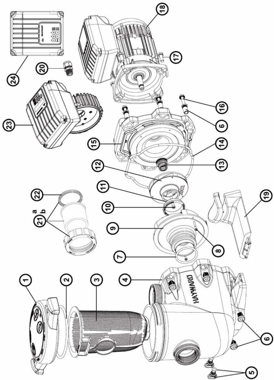
TRISTAR VSTD SERIES
SP3216VSTD
SP3220VSTD
| N° | Description · Description · Descripción · Descrição · Bezeichnung · Beschrijving · Descriizione · Beskrivning · Beskrivelse · Beskrivelse · Kúvaus ·Οικαυπη |
| 1 | Strainer cover · Covercle de préfiltre · Tapa de prefiltro · Tampa do filtro · Deckel · Zeef dekking · Coperchio prefilto · Silskydd · Siddeksel · Si dæksel · Silvili kansi · Kpbiika πρεφιντρα |
| 2 | Strainer cover O-Ring · Joint torque de préfiltre · Junta tórica · Junta tórica da tampa do filtro · O-Ring · De O-ring van de zeefdekking · Guarnizione O'ring · Silskydd O-ring · Siddeksel O-Ring · Sidaekele O-ring · Silvili kannen O-rengas · Üylohtηntelbne KoIbdo |
| 3 | Strainer basket · Panier de préfiltre · Cesto filtrante · Cesta do filtro · Filterkorb · Zeef mand · Cestino prefilto · Silkorg · Sil kurv · Si kurv · Silvili kori · KopzmaHa np |
| 4 | Pump Housing/Strainer · Corps de pompé et préfiltre · Cuerpo bomba y prefiltre · Corpo de bomba e préfiltre · Pumpengehäuse/Vorfilter · Lichaam van pomp en préfiltre · Corpo pompa/Prefilto · Pumphus/sil · Pumpehus/sil · Pumpehus/si · Pumpun kotel/sivilia · Kopnyc haccosa |
| 5 | Drain Plug · Bouchon de vidange · Tapón de vaciado · Pluge de dreno · Ablasschraube · Afvoerkanaal stop · Tappo di spurgo · Avlappeningsplugg · Dreineringsplugg · Bundprop · Tyhjennystulppa · Csinnaan pro6ka |
| 6 | Housing insert & seal plate spacer kit · Inserts de corps · Partes de cuerpo · Insertes de corps · KörperEinlagen · Inserts van lichamen · Inserzioni di corso · Husinsats & tättningsplatta distanssats · Avstandsett for husinnsats og tetningsplate · Husinsats & tättningsplade afstandssat · Kotelon sisäosa ja tiivistelevyn vällkesarja · Brvnka |
| 7 | Diffuser gasket · Joint de diffuseur · Junta de difusor · Junta de difusor · Dichtung · Verbindingsstuk van verspreider · Guarnizione diffusore · Diffusor packing · Diffuserpakning · Diffuserpakning · Hajottimen tiivistene · Trpoknádka |
| 8 | Disfuser screws (x2) · Vis de diffuseur (x2) · Tornillo de difusor (x2) · Tornillos do difusor (x2) · Zerstäuberschraube (x2) · Schroef van verspreider (x2) · Vite di diffusore (x2) · Spridningsskruvar (x2) · Sprederskrue (x2) · Sprederskrue (x2) · Hajottimen ruuvit (x2) · Kompliek TBIV (x2) |
| 9 | Diffuser · Diffuseur · Difusor · Leitapparat · Verspreide · Diffuseur · Difusor · Spreder · Diffuseur · Hajotin · Μινφύθρορ |
| 10 | Impeller screw · Vis de turbine · Tornillo de turbina · Tornillos de turbina · Turbinenschraube · Schroef van turbine · Vite di turbina · Impellerskruv · Impeller skru · Løbehjulskrue · Juoksupyöän rnuvi · Komplext Binhov |
| 11 | Ring for impeller · Bague pour turbine · Anillo para turbina · Ring de turbina · Ring für Laufrad · Ring voor Turbine · Anello · Ring für pumpjul · Ring for impeller · Ring til pumpejul · Rengas juoksupyöärille · Ülpontnienlboe KoIbdo |
| 12 | Impeller · Turbine · Turbina · Laufrad · Turbine · Girante · Impeller · Impeller · Løbehjul · Juoksupyöärä · KpbiNbattka |
| 13 | Shaft Seal assembly · Obturator mecanique · Cierre mecánico · Conjunto de selo · Motorhalterung · Verbindings assemblage · Tenuta meccanica · Axeltättningsenet · Akselettningsenet · Akseltättningsssamling · Akselettiivisteen kokoonpano · CanbHKB v cbope |
| 14 | Housing gasket · Joint de corps · Junta · Gaxeta da carcaça · Dichtung · Huisvestings pakking · Guarnizione corpo · Huspackning · Huspakning · Kotelon tiivistene · Trpoknádka |
| 15 | Seal plate · Plateau d'étancheité · Plato de cièrere · Placa do selo · Flansch · Verbindings plaat · Supporto di fissaggio · Tafningsplattla · Forseglingsplata · Tætningsplade · Tiivistelevny · Φaneeu |
| 16 | Housing bolt · Vis corps de pompé · Tornillo cabeza exagonal · Tornillos de tampão da carcaça · Sechskantschraube · Huisvestings GLB schroeveen Viti a testa esagonale · Husbolt · Husbolt · Husbolt · Kotelon pultti · Komplext boIntoB |
| 17 | Motor bolt · Vis moteur · Tornillo · Tornillos a motor · Sechskantschraube · Schroef motor · Viti · Motorbult · Motor bolt · Motor bolt |
| 18 | Motor · Moteur · Motor · Motor · Motor · Motore · Motor · Motor · Mottotti · ΕλektrodrivaatelB |
| 19 | Bracket motor support · Support de pompé · Soporte bomba · Suporte de montagem · Sockelteil · Opzettende steun · Supporto pompa · Faste motorstöd · Brakett motrøtte · Motrøtte til beslag · Motttorin kannatalintuki · Φaneeu ΕλektrodrivaatelB |
| 20 | Gland · Presse élopane · Prensa estopas · Imprena estopa · Kabel-Klemme · Klier · Pressacavo · Kortel · Kirtel · Gland · CaIbHik |
| 21a | Union connector kit 50 mm · Kit de raccord union 50 mm · Assemblie del conectar de la unión 50 mm · Conjunto do conectar da unión 50 mm · Anschluß-Stecker 50 mm · de assemblage van de unieschekaar 50 mm · Assemblie del connetto del sindacato 50 mm · Koppingssats 50 mm · Union koblingssett 50 mm · Unionstiksæt 50 mm · Litinsarja 50 mm · ΦiYTHR 50 MM |
| 21b | Union connector kit 63 mm · Kit de raccord union 63 mm · Assemblie del conectar de la unión 63 mm · Conjunto do conectar da unión 63 mm · Anschluß-Stecker 63 mm · de assemblage van de unieschekaar 63 mm · Assemblie del connetto del sindacato 63 mm · Koppingssats 63 mm · Union koblingssett 63 mm · Union stiksæt 63 mm · Litinsarja 63 mm · ΦiYTHR 63 MM |
| 21c | Fitting pack 2" USA Imperial · Pack Raccord 2" USA Imperial · Paquete de unión 2" USA Imperial 2" pacone de unión 2" USA Imperial · Passende Packung 2" USA Imperial · Montagepakket 2" USA Imperial · Pacchetto Union 2" USA Imperial · Fitting pack 2" USA Imperial · Fitting pack 2" USA Imperial · Assennuspakketti 2" USA Imperial · Komplext φiniHrob 2" |
| 22 | Union gasket · Joint pour raccord union · Junta tórica · Junta tórica de adaptorador · O-Ring · O'ring Dichtheidsadepter · Guarnizione O'ring · Unionspackning · Union pakning · Union ninin tiivistene · Trpoknádka |
| 23 | Electronic module VSTD - Modulelectronique VSTD - Modulo electronico VSTD - Modulo electronico VSTD - Modulo electronique VSTD - Modulo electronico VSTD - Modulo electronico VSTD - Modulo electronique VSTD - Modulo electronique VSTD - Modulo electronique VSTD - Modulo electronique VSTD - Modulo electronique VSTD - Modulo electronique VSTD - Modulo electronique VSTD - Modulo electronique VSTD - Modulo electronique VSTD - Modulo electronique VSTD - Modulo electronique VSTD - Modulo electronique VSTD - Modulo electronique VSTD -Modulo electronique VSTD - Modulo electronique VSTD - Modulo electronique VSTD - Modulo electronique VSTD - Modulo electronique VSTD - Modulo electronique VSTD - Modulo electronique VSTD - Modulo electronique VSTD - Modulo electronique VSTD - Modulo electronique VSTD - Modulo electronique VSTD - Modulo electronique VSTD - Modulo electroniques VSTD - Modulo electronique VSTD - Modulo electronique VSTD - Modulo electronique VSTD - Modulo electronique VSTD - Modulo electronique VSTD - Modulo electronique VSTD - Modulo electronique VSTD - Modulo electronique VSTD - Modulo electronique VSTD - Modulo electronique VSTD - Modulo electronique VSTD - Modulo electronique VSTD -.Modulo electronique VSTD - Modulo electronique VSTD - Modulo electronique VSTD - Modulo electronique VSTD - Modulo electronique VSTD - Modulo electronique VSTD - Modulo electronique VSTD - Modulo electronique VSTD - Modulo electronique VSTD - Modulo electronique VSTD - Modulo electronique VSTD - Modulo electronique VSTD - Modulo electroniquelmodullB |
| 24 | Electronic module VSTD - Modulelectronique VSTD - Modulo electronico VSTD - Modulo electronico VSTD - Modulo electronique VSTD - Modulo electronique VSTD - Modulo electronique VSTD - Modulo electronique VSTD - Modulo electronique VSTD - Modulo electronique VSTD - Modulo electronique VSTD - Modulo electronique VSTD - Modulo electronique VSTD - Modulo electronique VSTD |
| N° | Description / Description / Bezeichnung / Descripción / Beschrijving / Descrição / Onicanhe |
| 2+7+13+14 | Set of gaskets · Pack de joints · Juego de juntas · Conjunto de juntas · Satz Dichtungen · Set van pakkingen · Set di guarnizioni · Uppsätt-ning packningar · Sett med pakninger · Sæt med pakninger · Tiivistesarja · Komplèkt πρoknapodok |
| - | Ventilateur · Fan · Ventilador · Fan · Fan · Ventilador · Fan · Ventilator · Ventilator · Ventilator · Tuuletin · Běntvnätop |
| - | Capot ventilateur · Fan cover · Cubierta del ventilador · Ventilatordeksel · Lüfterhaube · Fan cobertura · Copriventola · Capotventilator · Capot ventilator · Capot ventilator · Capot tuuletin · Kojux Běntvnätopa |
| - | Motor Bearingsis Kit · Kit Roulements moteur · Kit de rodamientos de motor · Kit rolamente do motor · Motorlager-Kit · Motorlagers kit · Kitcuscinetto del motore · Motorlagersats · Motorlagersett · Motor lejesæt · Moottorin laakerit · Пodiumнійки DByratela KMplékt |
| - | Slinger · Larmier · Arandela Separación · Arandela Separación · Tropfing · Tropfing · Rondella di separazione · Slinger · Slinger · Slinger ·Slinger · Macnoxbemnoe кльцо |
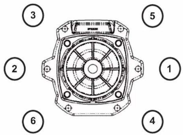
Ordre de serrage des boulons - Bolt tightening order - Orden de apriete de los pernos - Ordem de aperto dos parafusos - Anzugsreihenfolge der Bolzen - Volgorde waarin de bouten vastgedraaid moeten worden - Ordine di stringimento bulloni - Ordning for att dra at bultarna - Spændngsrækkefolge for bolte - Rekkefolge for tiltrekking av boltene - Pulttien kiristysjärestys - Порядok 3атякки солтов
185 INCH LBS
20.9 N m
K-FLO VSTD SERIES
SPK12615VSTD
| N° | Description · Description · Descripción · Descrição · Bezeichnung · Beschrijving · Descrição · Beskrivning · Beskrivelse · Beskrivelse · Kuvaus · Ömnacannes |
| 1 | Locking nut · Écrou couvercle préfiltre · Tuerca de cierre · Porca d tampa do pré-filtro · Mutter Vofilterdeckel · Moer deksel voorfilter · Dado coperchio préfiltro · Lasmutter · Lasmutter · Lasmétrik · Lukitusmutteri · Taima kpbiiu κrbyoδ κπilbtrauin |
| 2 | Cover kit (cover + o-ring) · Kit couvercle (coveverle + joint torque) · Conjunto tapa + junta · Kit da tampa (tampa + junta törica) · Deckelset (Deckel + O-ring) · Dekselset (deksel + O-ring) · Kit coperchio (coperchio + guarnizione torica) · Skyddssats (hölje + o-ring) · Dekselset (deksel + o-ring) · Däksaet (cover + o-ring) · Kansisarja (kansi + O-rengas) · Kompltekt kpbiiu (kpbiiu + kombévee yülpθnehe) |
| 3 | Cover o-ring · Joint torque couvercle · Junta de tampa · Junta törica da tampa · O-Ring Deckel · O-ring van deksel · Guarnizione torica coperchio · Tack o-ring · Dekk o-ring · Däk o-ring · Kannen O-rengas · Kombévee yülpθnehe · Cboiuk · Sil kury · Si kury · Siivilä kori · Manaj korpuzna rþob φínbtrauin |
| 4+5 | Strainer basket · Panier de préfiltre · Cestillo préfiltro · Cesto do pré-filtro · Vofilterkorb · Mand van voorfilter · Cesto prefiltro · Silkorg · Sil kury · Si kury · Siivilä kori · Manaj korpuzna rþob φínbtrauin |
| 7+8 | Drain kit · Kit vidange · Kit tapon desage · Kit de vazamento · Entleerungsset · Aftapset · Kit di spurgo · Avloppssats · Avlopssett · Afløbsaet · Viemärisarja · Habop onopoxheneia |
| 3+8+11+16+24 | Pump gasket kit · Jeu complet de joints pompe · Juego completo juntas · Jogo completo de juntas da bomba · Komplettet Satz Pumpen-dichtungen · Completset set van pompringen · Set completo di guarnizioni pompa · Pumppackingsats · Pumpepakingssett · Pumpepakingsatt · Pumpepakingsatt · Pumpepakingsatt · Pumpepakingsatt · Pumpepakingsatt · Pumpepakingsatt · Pumpepakingsatt · Pumpepakingsatt · Pumpepakingsatt · Pumpepakingsatt · Pumpepakingsatt · Pumpepakingsatt · Pumpepakingsatt · Pumpepakingsatt · Pumpepakingsatt · Pumpepakingsatt · Pumpepakingsatt · Pumpepaltschut · Pumpepakingsatt · Pumpepakingsatt · Pumpepakingsatt · Pumpepakingsatt · Pumpepakingsatt · Pumpepakingsatt · Pumpepakingsatt · Pumpepakingsatt · Pumpepakingsatt · Pumpepakingsatt · Pumpepakingsatt · Pumpepakingsatt · Pumpepakingsatt · Pumpepakingsatt · Pumpepakingsatt · Pumpepakingsatt · Pumpepalknottien • Kompuc nacoc |
| 10 | Pump casing · Corps de pompe · Cuero de bomba · Corpo da bomba · Pumpengehäuse · Pompuis · Corpo della bomba · Pomphus · Pumpehus · Pumpehus · Pumpun kotelo · Kompuc nacoc |
| 11 | Diffuser o-ring · Joint torque de diffuser · Junta difusor · Junta törica do difusor · O-Ring Diffusor · O-ring van diffusor · Guarnizione torica diffusore · Diffusor o-ring · Diffusor o-ring · Hajolimen O-rengas · Kolbévee yülpθnehe • Dlófφúzopa |
| 12 | Diffuser · Diffuseur · Difusor · Diffusor · Diffusor · Diffusor · Spreder · Diffuser · Hajotin · Dlófφúzopa |
| 13 | Impeller VS 1,5HP · Turbine VS 1,5 CV · Rodete VS 1,5 CV · Turbine VS 1,5 CV · Turbine VS 1,5 PS · Rotor VS 1,5 PK · Turbine VS 1,5 CV · Impeller VS 1,5HP · Impeller VS 1,5HK · Læbehjul VS 1,5HK · Juoksupyöra VS 1,5hν · Tübina VS 1,5 n.c. |
| 14+15 | Mechanical seal kit · Garniture mécanique · Conjunto retén · Vedação mecanica · Mechanische Dichtung · Mechanische dichtingen · Tenuta meccanica · Mekanism tättningsats · Mekanism tättningssett · Mekanism tättningssett · Mekanism tättningssett · Mekanism tättningssett · Mekanism tättningssett · Mekanism tättningssett · Mekanism tättningssett · Mekanism tättningssett · Mekanism tättningssett · Mekanism tättningssett · Mekanism tättningsset |
| 16 | Casing flange o-ring · Joint plateau d'etanchéité · Junta cuero union · Junta do disco de vedação · Dichtung Dichtplatte · O-ring af-dichtingsflens · Guarnizione flangia · Husfläns o-ring · Husfläns o-ring · Husflange o-ring · Kotelon laipan O-rengas · Ilpokladaka ylnonthertbno nllactnib |
| 17 | Casing flange · Plateau d'etanchéité · Cuero union · Disco de vedação · Dichtplatte · Afdichtingsflens · Flangia de tenuta · Husfläns · Husfläns · Huxflange · Kotelon laippa · Ylnonthertbno nllactnha |
| 18 | Motor 1,5HP VS Motor 1,5 CV VS Motor 1,5 CV VS Motor 1,5 PS VS Motor 1,5 PK VS Motor 1,5 CV VS Motor 1,5 hK VS Motor 1,5HK VS Motor 1,5HK VS Moottori 1,5hV VS Dávrgatentb 1,5 n.c. VS |
| 19 | Gland · Presse-étoupe · Prensa estopas · Bucim de empanque · Stopbüchse · Pakkingbus · Pressacavo Körtel · Kjertel · Kirtel · Gland · Ulnonthenbno kabellb no boid |
| 20 | Electronic module · Module électronique · Modulo electronico · Modulo eletrolico · Elektronikmodul • Elektronische module • Modulo eletronico · Elektronikmodul • Elektronik modul • Elektroninen modului • Κλecktorponnhi moduynb |
| 21 | User interface VSTD · Interface utiliseur VSTD · Interfaz de usoario VSTD · Повьателбский Intergéoc VSTD · Benutzerschnittstelle VSTD · Interface do'utilizar VSTD · Interfacia utente VSTD · Gebruikersinterface VSTD · Användargräsnsett VSTD · Brukergrensesnett VSTD · Brugergräenseflide VSTD · Käytöllittymä VSTD |
| 24+25 | Set of unions · Kit raccord union · Kit enlaces · Kit de unioes de ligacao · Verschraubungssatz · Set koppelstukken · Kit raccordi di collega-mento · Uppsättingn av fackforeninger - Sett med fagforeninger - Sæt af fagforeninger - Joukkko ammattiliittoja - Habop coedineneia union |
| 31+39+42+47 | Hardware kit · Kit visserie · Kit tornilleria completa · Kit de peças de fixação · Schraubensatz - Schroeven en moeren · Kit bulloneria -Hardvarusats · Maskinvaresett - Hardware saat - Laitteistolasjarja - Kompltekt peßböbsbýx detanen |
| 41 | Slinger · Pare-goutte · Paragotero · Anel defletor - Tropfschutz - Morsring - Anello paracqua - Slinger - Slinger - Slinger - Slinger - Kanelbhoe kolfzuo |
| 46+48 | Pumper support · Support de pompè· Base de bomba · Suporte da bomba · Pumpenträger · Pompbasis · Supporto della pompà · Pumpstöd · Pumpestøtte · Pumpestøtte · Pumpun tuki - Onopa nacoc |
| - | Fan HG 0,50-1,50HP M · Ventilator HS 0,50-1,50 CV M · Ventilator HG 0,50-1,50 CV M · Ventoinha HG 0,50-1,50 CV M · Lüfter HG 0,50-1,50PS M · Ventilator HG 0,50-1,50 PK M · Ventilatore HG 0,50-1,50 CV M · Flåkt HG 0,50-1,50HP M · Vîfte HG 0,50-1,50 HK M · Ventilator HG 0,50-1,50HK M · Túuletin HG 0,50-1,50HP M · Benthianetop HG 0,50-1,50 n.c. M |
| - | Fan cover VS · Capot ventilatore VS · Tapa ventilador VS · Tampa da ventoinha VS - Lüfterabdeckung VS - Ventilatorkap VSC - Coperchio ventilatore VS - Fläktkäpa - Vītfeledeksel VS - Ventilatordaeksel VS - Túulettimen kansi VS - Kpbiiua bevhnta ITPA |
| - | Bearings kit Motor RF 1 - Kit roulements moteur RF 1 - Kit rodamientos Motor RF 1 - Kit de rolamentos do motor RF 1 - Lagerset Motor RF 1 - Set lagers voor motor RF 1 - Kit cuscinetti motore RF 1 - Lagersets motor RF 1 - Lagersett Motor RF 1 - Lejesaet Motor RF 1 - Laakerisarja Moottori RF 1 - Hâbop noudinnapbov DBiraatener RF 1 |

HAYWARD
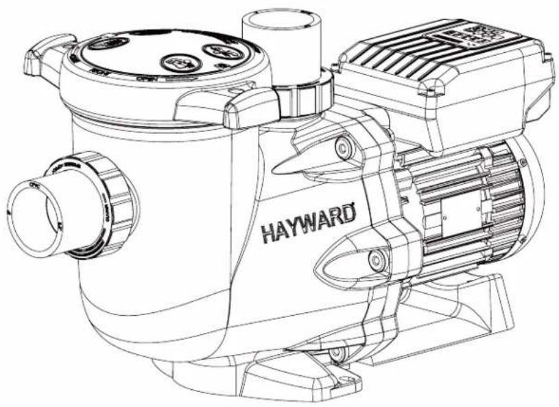
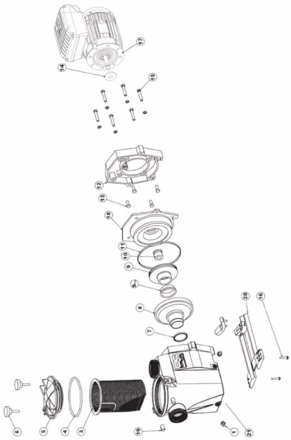
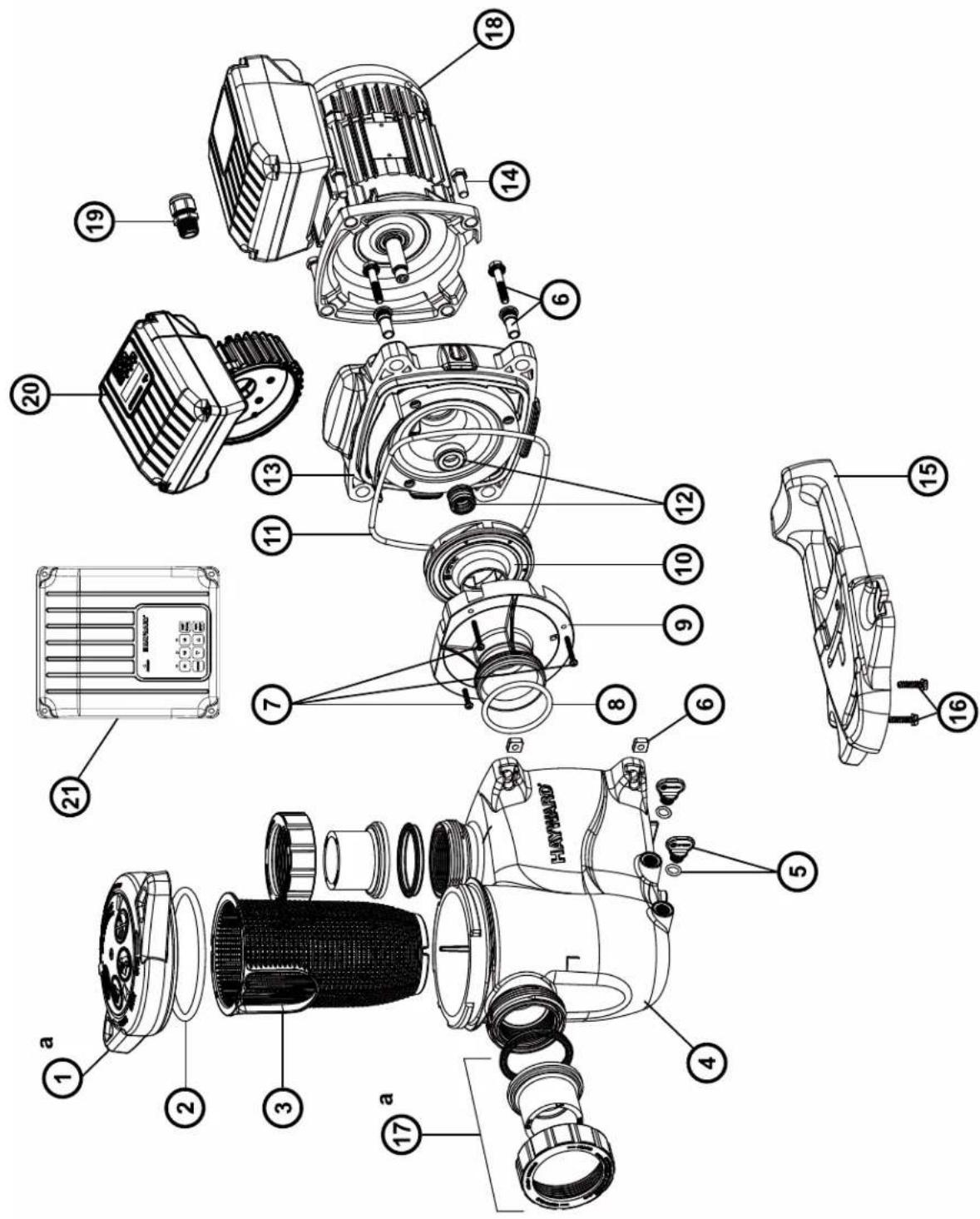
RS II VSTD SERIES
RS3016VSTD
RS3020VSTD
| N° | Description - Description - Descripción - Descrição - Bezeichnung - Beschrijving - Descriizione - Beskrivning - Beskrivelse - Beskrivelse - Kuvaus - Onicanhe |
| 1 | Drain Plug - Bouchon de vidange - Tapón de vaciado - Pluge de dreno - Ablasschraube - Afvoerkanaal stop - Tappo di spurgo - Avtappingsplugg - Dreineringsplugg - Bundprop - Tyhjennystulppa - Komplékt相关内容 - Inpbok |
| 3 | Strainer basket - Panier de préfiltre - Cesto filtrante - Cesta do filtrto - Filterkorb - Zeef mand - Cestino prefiltro - Silkorg - Sil kurv - Si kurv - Sivilä kori - Koprchina prepeinfiltra |
| 4 | Strainer cover O-Ring - Joint torique - Junta tórica - Yvnotnhtelbnoe kôlçuo - O-Ring - De O-ring van de zeefdekking - O-Ring de tampa do filtrto - Guarnizione O-ring - Silskydd O-ring - Sideksel O-Ring - Sidaksel O-ring - Siivilä kannen O-rengas - |
| 5 | Strainer cover - Couvercle de préfiltre - Tapa de prefiltro - Tampa do filtrto - Deckel - Zeef dekking - Coperchio prefiltro - Silskydd - Slideksel - Si daeksel - Siivilä kansi - Kpblska prepeinfiltra |
| 7 | Diffuser gasket - Joint de diffuseur - Junta de difusor - Junta de difusor - Dichtung - Verbindingsstuk van verspreider - Guarnizione diffusore - Diffusor packing - Diffuserpakning - Diffuserpakning - Hajottimen tiivistene - Inpkladka |
| 8 | Diffuser - Diffuseur - Difusor - Leitapparat - Verspreide - Diffusore - Difusor - Spreder - Diffuser - Hajotin - Дифύзор |
| 9 | Impeller - Turbine - Turbina - Turbine - Laufrad - Turbine - Girante - Impeller - Impeller - Læbehjul - Juoksupyörä - Крльнатka |
| 9 bis | Ring for impeller - Bague pour turbine - Anillo para turbine - Anel para turbine - Ring für Laufrad - Ring voor Turbine - Anello - Ring für pumphjul - Ring for impeller - Ring til pumpehjul - Rengas juoksupyörä - Yvnotnhtelbnoe kôlçuo |
| 10 | Seal assembly - Obturator mecanique - Cierre mecanico - Conjunto de selo - Motorhalterung - Verbindings assemblage - Tenuta meccanica - Tätningsmontering - Tätningsmontering - Tätningsssammling - Tiivisteen kokoonpano - Caibnik v cbope |
| 11 | Housing gasket - Joint de corps - Junta - Gaxeta da carcaça - Dichtung - Huisvestings pakking - Guarnizione corpo - Huspackning - Hus-pakning - Huspakning - Kotelon tiivistene - Inpkladka |
| 12 | Motor mounting plate - Support moteur - Soporte motor - Apoio a motor - Motorhalterung - Motorsteun - Supporto motore - Motor monteringsplatta - Motor monteringsplata - Motor monteringsplade - Moottorin asennuslevy - Фланец -等形式юдов ratеля |
| 13 | Motor cap screw - Vis moteur - Tornillo - Tornillos a motor - Sechskrantschraube - Schroeft motor - Viti - Motorskruv - Motorskrue - Motor hætteskrue - Moottorin kannen ruuvi - Komplékt винтob |
| 14 | Slinger - Larmier - Arandela Separación - Arandela Separación - Tropfing - Tropfing - Rondella di separazione - Slinger - Slinger - Slinger - Slinger - Macnocbemnoe kôlçuo |
| 15 | Housing cap screws - Vis corps de pompie - Tornillo cabeza exagonal - Tornillos de tampão da carcaça - Sechskanschraube - Huisvestings GLB schroeven - Viti a testa esagonale - Kapans skruvar - Husets hodeskrueer - Husets hætteskrueer - Kotelon Kannen ruuvit - Komplékt винтob |
| 16 | Cap screw - Vis support de pompie - Tornillo cabeza exagonal - Tornillos apoio de bomba - Sechskanschraube - Schroeft steun van pomp - Viti - Kapselskruv - Toppskrue - Skruelag - Kantaruuvi - Komplékt винтob |
| 17 | Motor - Moteur - Motor - Motor - Motor - Motore - Motor - Motor - Moottori -等形式юдов ratelj |
| 18 | Seal plate - Plateau d'etanchéité - Plato de cierre - Placa do selo - Flansch - Verbindings plaa - Supporto di fissaggio - Tätningsplatta - Forseglingsplata - Tätningsplade - Tiivistelevy - Фланец |
| 19+6 | Swivel nut + Hand knob - Ecrou rotule + Vis papillon - Rôtula + Tornillo maripo - Tuerca de giro+ Parafuso borboleta - Gewindezapfen + Flügelschraube - Wartel noot + Schroeft vinder - Perno Manopola di chiusura - Svangmutter + Handknopp - Svingmutter + handknapp - Drejemøtrik + Handknop - Käantömutteri + käsinnuppi - Komplékt винтob |
| 20 | Mounting bracket - Support de pompie - Soporte bomba - Suporte de montagem - Sockelteil - Opzettende steun - Supporto pompa - Monteringsfäste - Monteringsbrakett - Monteringsbeslag - Kiinnike - Montaxnajra stojka |
| 21 | Assembly Body RS II (body, basket, cover, feets) - Corporas assemblé RS II (Corps, panier, couvercle, pieds) - Cuerpo montado RS II (cuerpo, cesta, tapa, pie) - Corpo armado RSII (corpo, cesto, tampa, pé) - Zusammengesetzler körper RS II (körper, korb, deckel, fub) - Assemblage lichaam RS II (Lichaam, Zeef mand, Zeef dekking, Voeten) - Corpo riunito RS II (corpo, canestro, coperchio, piede) - Monteringskropp RS II (kropp, korg, lock, fötter) - Monteringskropp RS II (kropp, kurv, deksel, fötter) - Samlingskropp RS II (krop, kurv, dæksel, fodder) - Asennus-runko RS II (runko, kori, kansi, jalat) - Kopnyc hacoca b |
| 4+7+10+1114 | Set of gaskets - Pack de joints - Juego de juntas - Conjunto de juntas - Satz Dichtungen - Set van pakkingen - Set di guarnizioni - Uppsätt-ing packningar - Set med pakninger - Set med pakninger - Tivistesarja - Komplékt pröknaudok |
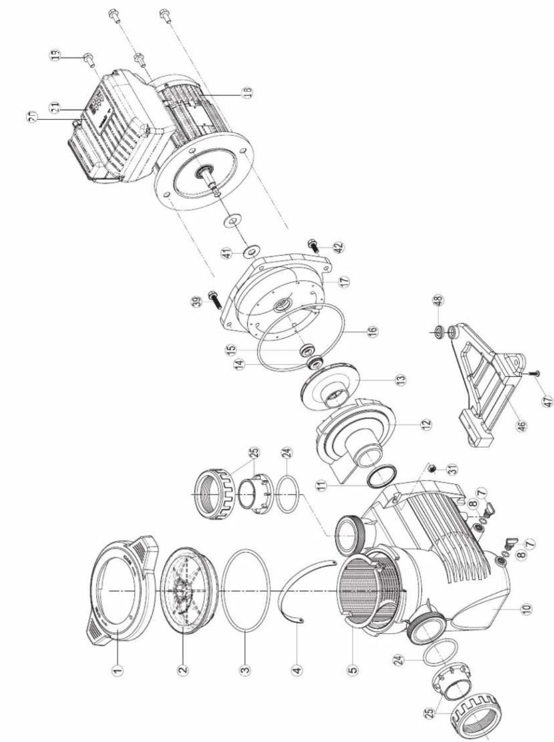
MAX FLO XL VSTD SERIES
SP2310VSTD
SP2315VSTD
| N° | Description · Description · Descripción · Descrição · Bezeichnung · Beschrijving · Descriizione · Beskrivning · Beskrivelse · Beskrivelse · Kúvaus · Oúnicahnne |
| 1 | Locking nut · Écrou couvercle préfiltré · Tuerca de ciere · Porca da tampa do pré-filtro · Mutter Vofilterdeckel · Moer deksel Voorfilter · Dado coperchio préfiltratio · Läsemutter · Läsemutter · Läsemétrik · Lukitusmutteri · Γαίκα κρυδικητρυθερον Φιπότραυημ |
| 2+3 | Cover kit (cover + o-ring) · Kit couvercle (coveverle + joint torque) · Conjunto tapa + junta · Kit da tampa (tampa + junta tórica) · Deckelset (Deckel + O-Ring) · Dekselset (deksel + O-ring) · Kit coperchio (coperchio + guarnizione torica) · Skyddssats (hölje + o-ring) · Dekselsett (deksel + o-ring) · Dæksæt (cover + o-ring) · Kansisarja (kansi + O-rengas) · Komplèkt kþbùskm (kþbùskm + kønbéveöe ylpóltnenhe) |
| 3 | Cover o-ring · Joint torque couvercle · Junta de tapa · Junta tórica da tampa · O-Ring Deckel · O-ring van deksel · Guarnizione torica coperchio · Tack o-ring · Dekk o-ring · Dæk o-ring · Kannen O-rengas · Kolbyeboe ylpóltnenhe · kþbùskm |
| 4+5 | Strainer basket · Panier de préfiltré · Cestillo préfiltré · Cesto do pré-filtro · Vofilterkorrb · Mand van voorfilter · Cesto prefiltré · Silkorg · Sil kurv · Si kurv · Siivilà kori · Manaj korpína rþuböv φιπlbṭraúns |
| 7+8 | Drain kit · Kit vidage · Kit tapon desague · Kit de vazamento · Entleerungsset · Aftapset · Kit di spurgo · 7+8 Avloppssats · 7+8 Avloppsett · 7+8 Aflobbaaet · 7+8 Viemärisarja · Hαβop onopoknêneu |
| 3+8+11+1624 | Pump gasket kit · Jeu complet de joints pompe · Juego completo juntas · Jogo completo de juntas da bomba · Komplettier Satz Pumpen-dichtungen · Complet set van pompringen · Set completo di guarnizioni pompa · Pumppackningsstats · Pumpepakningssett · Pumpekpakningssett · Pumpun tiivistasarja · Плелный habop уlpóltnenhi dña hacosa |
| 10 | Pump casing · Corps de pompe · Cuerpo de bomba · Corpo da bomba · Pumpengehäuse · Pompuiis · Corpo della pompa · Pumphus · Pumpehus · Pumpehus · Pumpun kotelo · Kopnyc hacosa |
| 11 | Diffuser o-ring · Joint torque de diffuseur · Junta difusor · Junta tórica do difusor · O-Ring Diffusor · Guarnizione torica diffusore · Diffusor o-ring · Diffusor o-ring · Hajottimen O-rengas · Kolbyeboe ylpóltnenhe · dinφύzopa |
| 12 | Diffuser · Diffuseur · Difusor · Difusor · Diffusor · Diffusor · Spreder · Diffuser · Hajotin · Diñφóuzop |
| 13 | Impeller VS 1,5HP · Turbine VS 1,5 CV · Rodele VS 1,5 CV · Turbine VS 1,5 CV · Turbine VS 1,5 PS · Rotor VS 1,5 PK · Turbina VS 1,5 CV · Impeller VS 1,5HP · Impeller VS 1,5HK · Lebehujl VS 1,5HK · Juoksupörä VS 1,5hv · Tüpbina VS 1,5 n.c. |
| 14+15 | Mechanical seal kit · Garniture mécanique · Conjunto retén · Vedação mecânia · Mechanische Dichtung · Mechanische dichtingen · Tenuta meccanica · Mekanism tättningsssats · Mekanism tettningssett · Mekanism tättningssett · Mekanism tättningssett · Mekanism tättningssett · Mekanism tättningssett · Mekanism tättningssett · Mekanism tättningssett · Mekanism tättningssett · Mekanism tättningssett · Mekanism tättningssett · Mekanism tättningssett · Mekanism tüttningssett · Mekanism tättningssett · Mekanism tättningssett · Mekanism tättningssett · Mekanism tättningssett · Mekanism tättningssett · Mekanism tättningssett · Mekanism tättningssett · Mekanism tättningssett · Mekanism tättningssett · Mekanism töltnoche |
| 16 | Casing flange o-ring · Joint plateau d'étanchéité · Junta cuero union · Junta do disco de vedação · Dichtung Dichtplatte · O-ring af-dichtingsfliens · Guarnizione flangia · Husfläns o-ring · Husflens o-ring · Husflange o-ring · Kotelon laipan O-rengas · Trpokladka ylpóltnetblýh noiactnly |
| 17 | Casing flange · Plateau d'étanchéité · Cuerpo union · Disco de vedação · Dichtplatte · Afdichtingsfliens · Flancia di tenuta · Husfläns · Husfläns · Husflange · Kotelon laippa · Ylpóltnetblýh noiactnla |
| 18+48 | Pump support · Support de pompé · Base de bomba · Suporte da bomba · Pumpenträger · Pompbasis · Supporto della pompa · Pumpstöd · Pumpestotte · Pumpestotte · Pumpun tuki · Onopa hacosa |
| 18 | Motor 1,5HP VS · Moteur 1,5 CV VS · Motor 1,5 CV VS · Motor 1,5 CV VS · Motor 1,5 PK VS · Motore 1,5 CV VS · Motor 1,5 hk VS · Motor 1,5HK VS · Motor 1,5HK VS · Moottori 1,5hv VS · Débratétenb. 1,5 n.c. VS |
| 19 | Gland · Presse-étoupe · Prensa estopas · Bucim de empanque · Stopbüchse · Pakkingbus · Pressacavo · Körtel · Kjertel · Kirtel · Gland · Ülpóltnenhlýh noiactnly |
| 20 | Electronic module · Module d'électronique · Modulo electronico · Modulo electrónico · Elektronikmodul · Elektronische module · Modulo elec-tronico moduli |
| 21 | User interface VSTD · Interface utilisateur VSTD · Interfaz de usoario VSTD · Interface do usoilizar VHSTD · Benutzerschnittstelle VSTD · Gebruikersinterface VSTD · Interfaccia utente VSTD · Användargränssnitt VSTD · Bruerkgrensesnitt VSTD · Brugergräenseflate VSTD · Käytolittymä VSTD · Повьовелуckи с interpelléc s VSTD |
| 24+25 | Set of unions · Kit raccord union · Kit encases · Kit de unioes de ligacao · Verschraubungssatz · Set koppelstukken · Kit raccordi di collega-mento · Uppsättning av fackforeninger · Sett med fagforendering - Sael af fagforendering - Joukko ammattilittoja · Habop coeurinienea union |
| 31+39+42+47 | Hardware kit · Kit viserie · Kit tornilleria completa · Kit de peças de fixação · Schraubensatz · Schroeven en moeren · Kit bulloneria · Hård-vasumsats · Maskinvaresett · Hardware saat - Laitteistosarja · Komplèkt peşibobv détanénei |
| 41 | Slinger · Pare-goutte · Paragotero · Anel defletor · Tropfschutz · Morsring · Anello paracqua · Slinger · Slinger · Slinger · Kanelhoe konlviz |
| - | Fan HG 0,50-1,50HP M · Ventilatorur HG 0,50-1,50 CV M · Ventilatorur HG 0,50-1,50 CV M · Ventoinha HG 0,50-1,50 CV M · Lüfter HG 0,50-1,50 PS M · Ventilatorur HG 0,50-1,50 PK M · Ventilatore HG 0,50-1,50 CV M · Fläkt HG 0,50-1,50 HP M · Vitef HG 0,50-1,50 HK M · Vitef HG 0,50-1,50 n.c. M |
| - | Fan cover VS · Capot ventilateur VST - Tapa ventilateur VST - Tapa da ventoinha VS - Lüfterabdeckung VS - Ventilatorkap VC - Coperchio ventilatore VS - Fläktkäpa VS - Vītdefdekel VS - Vītulettimien kansi VS - Kþbùka bevtinetaropa VS |
| - | Bearings kit Motor RF 1 · Kit roulements moteur RF 1 · Kit rodamientos Motor RF 1 · Kit de rolamentos do motor RF 1 · Lagerset Motor RF 1 · Laakeri-sarja Moottori RF 1 · Habop podušnýkov dBiratěteя RF 1 |
Ordre de serrage des boulons - Bolt tightening order - Orden de apriete de los permos - Ordem de aperto dos parafusos - Anzugsreihenfolge der Bolzen - Volgorde waarin de bouten vastgedraaid moeten worden - Ordine di stringimento bulloni - Ordning for att dra at bulturna - Spændingsrækkefolge for bolte - Rekkefolge for tiltrekking av boltene - Pulttien kiristysjärestys - Nopdok 3atjckn 60Tob
185 INCH LBS
20.9 N m
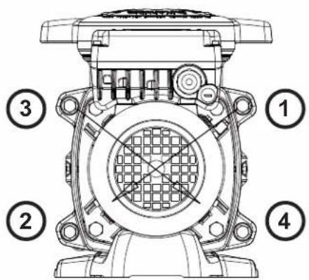

HAYWARD
SUPERPUMP VSTD
SP2611VSTD
SP2616VSTD
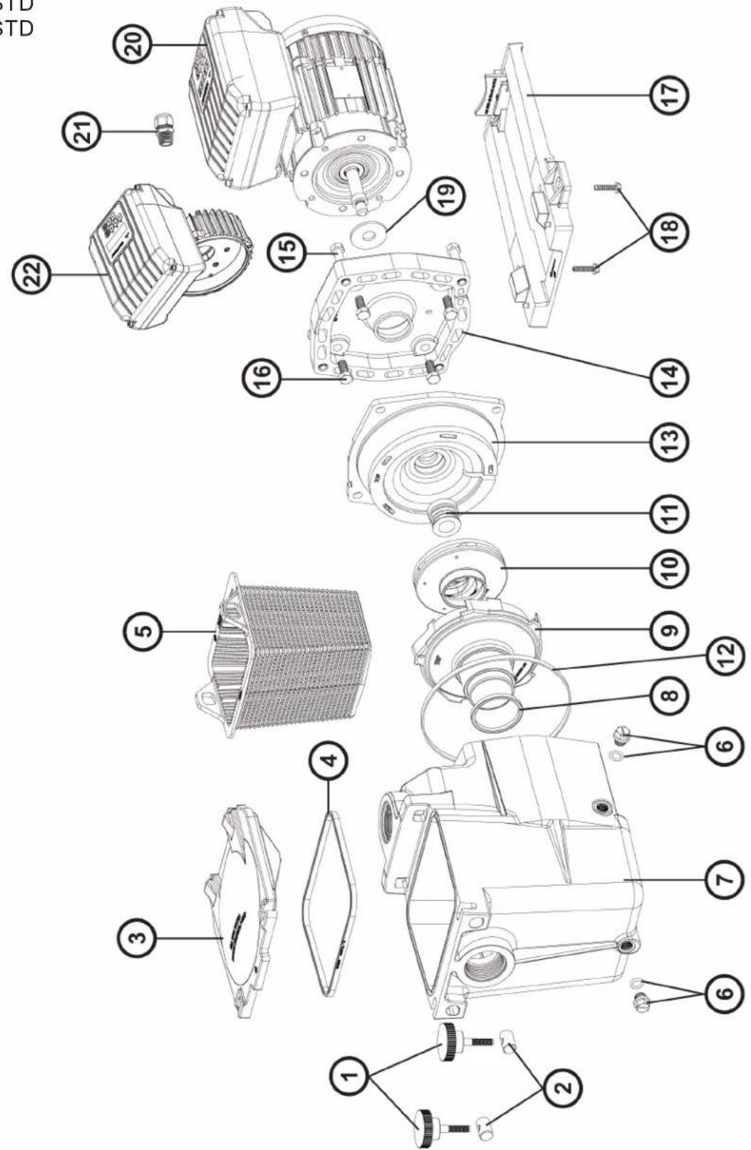
| N° | Description · Description · Descripción · Descrição · Bezeichnung · Beschrijving · Descriizione · Beskrivning · Beskrivelse · Beskrivelse · Kūvaus · Oùncanhe |
| 1+2 | Swivel nut + Hand knob - Ecrou rotule + Vis papillon - Rótila + Tornillo mariposa - Tuerca de giro + Parafuso borboleta - Gewindezapfen + Flügelschraube - Wartel noot + Schroeif vlinder - Perno girevole + Manopola di chiusura - Svangmutter + Handknopp - Svingmutter + handknapp - Drejemétrik + Händknop - Käantömutteri + käsünppi - Komplétrk Btvnok i BVnTob |
| 3 | Strainer cover - Couvercle de préfiltre - Tapa de prefiltre - Tampa do filtrato - Deckel - Zeef dekking - Coperchio prefilto - Silkydd - Sildeksel - Si dæksel - Sivilà kansi - Kpbuika prepeñilbtra |
| 4 | Lid gasket - Joint de préfiltre - Junta de prefilto - Junta préfiltre - Dichtung - Verbindungsstuk van préfiltre - Guarnizione prefilto - Lockets packing - Lokkpakning - Lågpakning - Kannen tivistete - Prøknaedka |
| 5 | Strainer basket - Panier de préfiltre - Cesto filtrante - Cesta do filtrato - Filterkorb - Zeef mand - Cestino prefilto - Silkorg - Sil kurv - Si kurv - Sivilä kori - Korpzma napevnbtra |
| 6 | Drain Plug - Bouchon de vidange - Tapón de vaciado - Pluge de dreno - Ablasschaube - Afvoerkanaal stop - Tappo di spurgo - Avtappingsplugg - Dreineringsplugg - Bundprop - Tyhjennystulpa - Komplétrk cnibnbix pröbk |
| 7 | Pump Housing/Strainer - Corps de pompé et préfiltre - Cuero bomba y prefiltre - Corpo de bomba e préfiltre - Pumpengehäuse/Vorfilter - Lichaam van pomp en préfiltre - Corpo pompa / Prefilto - Pumphus/sil - Pumpehus/sil - Pumpehus.si - Pumpun kotelo/sivilà - Kopnyc hacosa |
| 8 | Diffuser gasket - Joint de diffuseur - Junta de difusor - Junta de difusor - Dichtung - Verbindungsstuk van verspreider - Guarnizione diffusore - Diffusor packing - Diffuserpakning - Diffuserpackaging - Hajottimen tivistete - prôknaedka |
| 9 | Diffuser - Diffuseur - Difusor - Leitaparat - Verspreide - Diffusore - Diffusor - Spreder - Hajotin - Dnffpuzor |
| 10 | Impeller - Turbine - Turbine - Turbine - Laufrad - Turbine - Girante - Impeller - Impeller - Læbehul - Juoksuppyörä - Kpbuika |
| 11 | Seal assembly - Obturateur mécanique - Cierre mecanico - Conjunto de selo - Motorhalterung - Verbindings assemblage - Tenuta meccanica - Tättningsmontering - Tettningsmontering - Taelingsamling - Tiiisteen kokoopano - Caßniz B cbope |
| 12 | Housing gasket - Joint de corps - Junta - Gaxeta da carcaça - Dichtung - Huisvestings pakking - Guarnizione corpo - Huspacknong - Hus-pakning - Huspakning - Kotelon tivistete - Prøknaedka |
| 13+14 | Seal plate+Motor mounting plate - Plateau d'etanchée+Support moteur - Plato de ciere+Soporte motor - Placa do selo+Apoio a motor - Flansch+Motorhalterung - Verbindings plaat+Motorsteun - Supporto di fissaggio+Supporto motore - Taelingsplatta+Motormonteringsplatta - Tettningsplate+Motormonteringsplata - Taelingsplade+Motor monteringsplade - Tiiistelevy + moottorin asennuslevy - Φhanee+Φhanee anektrobnate |
| 15 | Housing screw - Vis plateau d'etanchée - Tornillo de cabeza hexagonal - Tornillos de carcaça - Sechskantschraube - Huisvestings schroeven - Viti esagonali - Husskruv - Husskrue - Husskrue - Kotelon ruuvi - Nabop bintob |
| 16 | Motor cap screw - Vis moteur - Tornillo - Tornillos a motor - Sechskantschraube - Schroef motor - Viti - Motorskruv - Motorskrue - Motor haettskruve - Moottorin kann ruuvi - Nabop bintob |
| 17 | Mounting bracket - Support de pompé - Soporte bomba - Suporte de montagem - Sockelteil - Opzettende steun - Supporto pompa - Monte-ringsfaste - Monteringsbraktt - Monteringsbeslag - Kiinnike - Montajnha stojka |
| 18 | Cap screw - Vis support de pompé - Tornillo cabaex axonal - Parafuso apoyo de bomba - Sechskanschraube - Schroef steun van pomp - Viti - Kapselskruv - Toppskruve - Skruelag - Kantaruuvvi - Nabop bintob |
| 19 | Slinger - Larmir - Arandela Separación - Arandela Separación - Tropfing - Tropfing - Rondella di separazione - Slinger - Slinger - Slinger - Slinger - Maclonobemnoe kòbdo |
| 20 | Motor - Moteur - Motor - Motor - Motor - Motore - Motor - Motor - Mottori - Εnektrodnigatentb |
| 21 | Gland - Presse étoupe - Prensa estopas - Imprensa estopa - Kabel-Klemme - Klier - Pressacavo - Kortel - Kjertel - Kirtel - Gland - Caßniz 1 SPX1100PE 71,19 |
| 22 | Electronic module - Module electronic - Modulo electrónico - Modulo electrónico-Modul - Elektronische module - Modulo eletronico - Elektronisk modul - Elektronisk modul - Elektroninen modului - Εnektronnhi moduynb |
| 23 | User interface - Interface utilisateur - interfaz de usoario - Interface do usoario - Benutzerschnittstelle - gebrukersinterface - interfaccia utente - Användargränssnitt - Brukergrensesnitt - brugergrønseflade - Käytollittymä - interpfænc noIb3obatena |
| 4+8+11+12+19 | Set of gaskets - Pack de joints - Juego de juntas - Conquito de juntas - Satz Dichtungen - Set van pakkingen - Set di guarnizioni - Up-psättning packninger - Sett med pakninger - Saet med pakninger - Komnnekt prôknaed |
| - | Fan - Ventilateur - Ventilador - Fan - Ventilador - Fan - Fläkt - Fan - Ventilator - Tuuletin - benvieta |
| - | Fan cover - Capot ventilateur - Cubierta del ventilador - Ventilatordeksel - Lüfterhaube - Fan cobertura - Copriventola - Fläktkäpa - Vift-edeksel - Ventilatordaeksel - Tuulettinen kansi - Koxych benvieta |
| - | Motor Bearings Kit - Kit Roulements moteur - Kit de rodamenteicos de motor - Kit rolamenti do motor - Motorlager-Kit - Motorlagers kit - Kit cuscinetto del motore - Motorlagersats - Motorlagerssett - Motor lejesæt - Moottorin laakerit - Ipondinini ki dbratertema - komnnekt |
| - | Superpurnp 2" male to 1", female retrofit kit - Superpurnp 2" / 1,5" kit adaptateur - Superpurnp kit adaplorado 2" / 1,5" - Superpurnp kit adapatran 2" / 1,5" - Superpurnp 2" hane till 1,5" hona aftermontingsatt - Superpurnp 2" hann til 1,5" hune aftermontingssaat - Superpurnp 2" uros-1,5" naaras jäklaisennussarja - Komnnekt nepexodnikov Superpurnp 2" / 1,5" |
E-FLO VSTD SERIES
EFLO126115VSTD
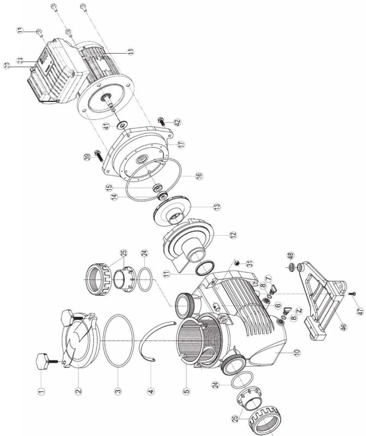
| N° | Description · Description · Descripción · Descrição · Bezeichnung · Beschrijving · Descrição · Beskrivning · Beskrivelse · Beskrivelse · Kuvaus · Onilcanne | |
| 1 | Locking nut · Écrou couvercle préfiltre · Tuerca de cierre · Porca da tampa do pré-filtro · Mutter Vofilterdeckel · Moer deksel voorfilter · Dado coperchio préfiltro · Lasmutter · Lasmutter · Lsemétrik · Lukitusmutteri · Taima kpbûkri rþubörø ømbertraquin | |
| 2 | Cover · Couvercle · Tapa · Tampa · Deckel · Deksel · Coperchio · Hölje · Deksel · Cover · Kansi · Kpbûkka | |
| 3 | Cover o-ring · Joint torique couvercle · Junta de tapa · Junta tórica da tampa · O-Ring Deckel · O-ring van deksel · Guarnizione torica coperchio · Tack o-ring · Dekk o-ring · Dæk o-ring · Kannen O-rengas · Kpbüeboe уlpntenhme kpbûkki | |
| 4+5 | Strainer basket · Panier de préfiltre · Cestillo préfiltro · Cesto do pré-filtro · Vofilterkorb · Mand van voorfilter · Cesto prefiltro · Silkorg · Sil kurv · Si kurv · Silvãå kori · Manja korpêna rþubörø ømbertraquin | |
| 7+8 | Drain kit · Kit vidange · Kit tapon desague · Kit de vazamento · Entleerungsset · Aflapset · Kit di spurgo · Avloppssats · Avlopssett · Afløbsæt · Viemärisarja · Hübop onopoxhennia | |
| 3+8+11+16+24 | Pump gasket kit · Jeu complét de joints pompe · Juego completo juntas de bomba · Kompletter Satz Pumpen-dichtungen · Complet set van pompringen · Set completo di guarnizioni pompa · Pumppackingsats · Pumpepakningssett · Pumpepak-ningsæt · Pumpun tiivistasarja · Плпный habр уlpntenhne對於 haccova | |
| 10 | Pump casing · Corps de pompe · Cuerpo de bomba · Corpo da bomba · Pumpengehäuse · Pompuis · Corpo della pompa · Pumphus · Pumpehus · Pumpehus · Pumpun kotelo · Kopnys haccova | |
| 11 | Diffuser o-ring · Joint torque de diffuseur · Junta difusor · Junta tórica do difusor · O-Ring Diffusor · O-ring van diffusor · Guarnizione torica diffusore · Diffusor o-ring · Diffusor o-ring · Hajottimen O-rengas · Kolbüeboe уlpntenhne dinφфузopa | |
| 12 | Diffuser · Diffuseur · Difusor · Difusor · Diffusor · Diffusor · Spreder · Diffuser · Hajotin · Diñóffyuzop | |
| 13 | Impeller VS 1,5HP · Turbine VS 1,5 CV · Rodete VS 1,5 CV · Turbine VS 1,5 CV · Turbine VS 1,5 PS · Rotor VS 1,5 PK · Turbina VS 1,5 CV · Impeller VS 1,5HP · Impeller VS 1,5HK · Læbehul VS 1,5HK · Juoksupýörä VS 1,5hν · Tþrbína VS 1,5 π.c. | |
| 14+15 | Mechanical seal kit · Garniture mécanique · Conjunto retén · Vedação mecânia · Mechanische Dichtung · Mechanische dichtingen · Tenuta meccanica · Mekanism tätningssats · Mekanism tätningssett · Mekanism tätningssaat · Mekaaninen tīvistasarja · Měkançeeckoe уlpntenhne | |
| 16 | Casing flange o-ring · Joint plateau d'étanchêté · Junta cuero union · Junta do disco de vedação · Dichtung Dichtplatte · O-ring af-dichtingsflens · Guarnizione flangía · Husfläns o-ring · Husflens o-ring · Husflange o-ring · Kotelon laipan O-rengas · Trpoknáka уlpntenhö nn pλactnvh | |
| 17 | Casing flange · Plateau d'étanchêté · Cuerpo union · Disco de vedação · Dichtplatte · Afdichtingsflens · Flangia de tenuta · Husfläns · Hus-flens · Husflange · Kotelon laippa · UþnoTnHnIeBnA nn pλactnha | |
| 18 | Motor 1,5HP VS · Moteur 1,5 CV VS · Motor 1,5 CV VS · Motor 1,5 PS VS · Motor 1,5 PK VS · Motore 1,5 CV VS · Motor 1,5hν VS · Moottori 1,5hν VS · Débratertel 1,5π.c. VS | |
| 19 | Gland · Presse-étoupé · Prensa estopas · Bucim de empanque · Stopfüchse · Pakkingbus · Pressacavo · Körtel · Kjertel · Kirtel · Gland · UþnpTnHnIeBnB nn boid | |
| 20 | Electronic module · Module électronique · Modulo electronico · Modulo elétrico · Elektronikmodul · Elektronische module · Modulo eletronico · Elektronikmodul · Elektronische module · Modulo eletronico · Elektronik modul · Elektronik modul · Elektroninen moduli · Θeiktonnien nn moduIb | |
| 21 | User interface VSTD · Interface utilisateur VSTD · Interfaz de usario VSTD · Повьотавельский interperféiec VSTD · Benutzerschnittstelle VSTD · Interface do'utilizator VSTD · Interfacchia utente VSTD · Gebruikersinterface VSTD · Användargränssnit VSTD · Brukergrensesmitt VSTD · Brugergræanseflade VSTD · Käytöllitymä Å VSTD | |
| 24+25 | Set of unions · Kit raccord union · Kit enlaces · Kit de uniónes de ligacao · Verschraubungssatz · Set koppelstukken · Kit raccordi di collega-mento · Uppsätting n av fackföringar · Sett med fackföringer ùsaf af fackföringer · Joukko ammattiliittoja · Habop coedineneion union | |
| 31+3942+47 | Hardware kit · Kit visserie · Kit tornilleria completa · Kit de peças de fixação · Schraubensatz · Schroeven en moeren · Kit bulleronia · Hårdvarunsats · Maskinvaresett · Hardware sæt · Laiteistosarja · Komplèkt reëböbux detanèle | |
| 41 | Slinger · Pare-goutte · Paragoto | Anel defletor · Tropfschutz · Morsring · Anello paracqua · Slinger · Slinger · Slinger · Slinger · Kanelhneoe konyo |
| 46+48 | Pump support · Support de pompé · Base de bomba · Suporte da bomba · Pumpenträger · Pompbasis · Supporta della pompa · Pumpstöd · Pumpestøtte · Pumpestøtte · Pumpun tuki · Onopa haccova | |
| 4+8+11+12+19 | Set of gaskets · Pack de joints · Juego de juntas · Conjunto de juntas · Satz Dichtungen · Set van pakingen · Set di guarmizioni · Up-psättning packninger · Sett med pakninger · Saet med pakninger · Komplèkt nepoknádox | |
| - | Fan · Ventilateur · Ventilador · Ventoinha · Lüfter · Ventilator · Ventilatore · Vîfte · Tuuletin · Benthiónatop | |
| - | Fan cover VS · Capot ventilateur VS · Tapa ventilator VS · Tampa da ventoinha VS · Lüfterabdeckung VS · Ventilatorkap VS · Coperchio ventilatore VS · Fläktkäpa VS · Vîftedeksel VS · VentilatordækSEL VS · Tuulettimen kansi VS · Kpbûkka Benthiónatop VS | |
| - | Bearings kit Motor · Kit roulements moteur · Kit rodamientos Motor · Kit de rolamenteos do motor · Lagerset Motor · Set lagers voor motor · Kit cuscinetti motore · Lagersats Motor · Lejesæt Motor · Laakeri-sarma Moottori · Habop noòmminnkov DBiratentena | |
CONDITIONS DE GARANTIE ET EXCLUSIONS POUR LES PAYS DE L'UNION EUROPEENNE
WARRANTY CONDITIONS AND EXCLUSIONS FOR EU COUNTRIES
All HAYWARD® products are covered for manufacturing defects or material defects for a warranty period of 3 years as of date of purchases. Any warranty claim should be accompanied by evidence of purchase, indicating date of purchase. We would therefore advise you to keep your invoice.
The HAYWARD® warranty is limited to repair or replacement, as chosen by HAYWARD®, of the faulty products, provided that they have been subjected to normal use, in compliance with the guidelines given in their user guides, provided that the products have not been altered in any way, and provided that they have been used exclusively with HAYWARD® parts and components. The warranty does not cover damage due to frost and to chemicals. Any other costs (transport, labour, etc.) are excluded from the warranty.
HAYWARD® may not be held liable for any direct or indirect damage resulting from incorrect installation, incorrect connection, or incorrect operation of a product.
In order to claim on a warranty and in order to request repair or replacement of an article, please ask your dealer.
No equipment returned to our factory will be accepted without our prior written approval.
Wearing parts are not covered by the warranty.
CONDICIONES DE GARANTÍA Y EXCLUSIONES PARA PAÍSES DE LA UNión EUROPEA
TAPAHINHbIE YCIOBnI NCKIOUeHnI DnI CTPAH EBPOENCKORO COIO3A
Ha BCE n3dennn KOMnHnn «HYWARD®» pacnpoctpaHreTcra pAHNTn B cnyae obHapyKeHH npOn3BocCTBeHHbIX n6o MaTePnAblbHX deΦeKTOB cpoKOM Ha 3 rOda, HauHnA C daTbI NOKynK. K No6bIM npTeHnM NO rapaHTm CneDyET B o6a3aTeNbHOM nopJrke npuIaratb ToK0a3aTeNbTO bOKynKn, BKIOUay DaTy ee COBepHeHH. NToTMy Mbl HactoTbeHo peKOMeHdyem Bam coXpAHrTB nCet-ФakTypy BMEc c TOBAPHO HAKnADHO HA n3dennie.
IapaHTn, npedocTabMaHa n3dennKOMnHn HAYWARD®), orpaHnUbaetcpeMOHTom nnn 3aMeHOJ deΦeKTHbIX n3denn no Bbl6opy KOMnAHn HAYWARD®), npnycOBn nx HopmaJIbHO 3KcIIpyataun C cO6IIOHeHem Tpe6oBaHn, npnbEeHHbIX b INx (PykoBOCTBAX), a TaKke NOpda3yMeBa, yTO n3denn 3TN He npDBePraNcB KaKM-1n60 KOHCTpyKTNBHM N3MeHEHm MOnDfKnAuaHm, uTO NCnOLb3OBaJIncb OHN NCKNIuOHTeBn BOkyne C KOMNoHETamn I npnaHdNekHoCTaMn, nOCTabJIeMbIM KOMnHaue «HAYWARD®). RapaHTn He pacnpocTpanReTcH Na NoBpeJDeHn, npnuHHeHbIe Bo3dEChTBEm Hn3kXn Tempepatypn nn XmHKaToB. Bce npOye paCXoDb (tpaHcnOpT, ocbnykBaHne n.T.n.) n3 rapaHTn NCKNUOHeHbI.
KOMnHnR HAYWARD® He HeceT OTBeTCTBeHHocTn 3a IIO6o PnPMo KOCBeHHbYuep6, NOHeceHHb BCJeCTBne HeHaIeJxueyctahOBKn, CoeUHeHnN INN EKcPnYataun N3dEInn.
IITTO, UTObI pTeBbTb npTeH3n I O rapaHTn, paBHO KAK N IOTpe6oBaTb peMOHTa JIN6O 3ameHb N3dEJIy, peKOMeHdyem Bam oBpaatabcra K CBOemy dInepy.
I3eHnna, Bo3BaPaeHHbIe Ha Hau 3aOo-n3rOToBntJIb, He 6ydy T npHraTb6e3 HaWero npEBApHTbHO rncbMeHHoro corNaCn.
Hactoiaa rapaHTna He paacnpoctpaHReTc Ha n3HaunBaembie qactn.

HAYWARD
Provision on waste electrical and electronic equipment from professionals. In accordance with Directive 2012/19/EU on the management of waste electrical and electronic equipment, this pump must be taken to a separate collection point. Contact your distributor for more information.
The proper management of electrical and electronic equipment helps to prevent damage to the environment and harm to human health. In accordance with Directive 2006/66/EC of the Council of the European Union of 6 September 2006 and with the waste that electrical and electronic equipment generates, the symbol accompanying this manual indicates that the battery incorporated in the pump must be disposed of separately.
When the battery reaches the end of its life, it should be removed and taken to a separate collection point.
STEP1: Remove the power of the pump
-STEP2: Remove the user interface lid
Unscrew the four screws of the corners. After it, carefully remove the lid. A wire is connected between the UI board and the PFC board.
A Philips screwdriver should be necessary.
FR - DESCRIPTION DES ÉTAPES
WAR2.3BNeuebIIOHueCKoeYCTPOINCTBO BBOdaNOJIb3OBaTeNbCKORO INHTepeEca
BbkyntbYehtpe BnHa no yrna. Nocne 3Toro akkypaTHo nBnEyb nornueckoe ycTPOCTBO BBOda.
NepaTHa nata noB3OBaTeBcKOrnHTeppeca n neaTHa nata KOMneHcaunn Ko3oPmUeHTa
MOUHOCTN COEINHEHBI NPOBODOM
Ipa6oTbI notpe6yetc KpctOBaB OTBeptKa.

- EN - STEP3: Find the battery location.
- FR - ÉTAPE 3: Trouvez l'emplacement de la pile.
- ES - PASO 3: Encontrar la ubicacion de la pila.
- PT - PASSO 3: Encontrar a localização da bateria.
- DE - SCHRITT 3: Suchen sie die installationsstelle der batterie.
- NL - STAP 3: Deplaats van de batterij zoeken.
- IT - FASE 3: Individuare l'ubicazione della batteria.
SWE-STEG3: Lokalisera batteriet.
DA-TRIN3:Find batteriets placering.
NO -TRINN 3: Finn ut hvor batteriet sitter.
- FI - VAIHE3: Etsi akun sijaintipaikka.
RU-UAΓ3.HaHTM MeCTO yCTAHOKBK 6aTape
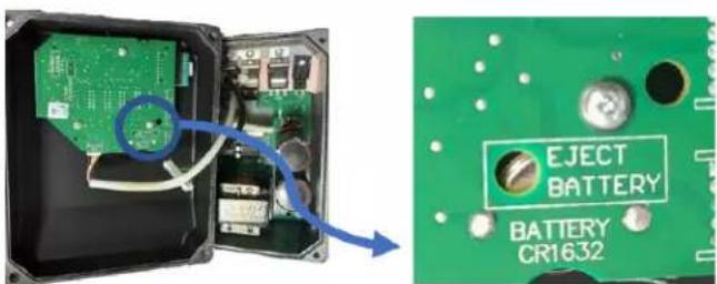
EN - STEP4:REMOVE THE BATTERY
Using a tool (small screwdriver or similar) introduce it into the hole indicated in the board for this purpose and carefully push the battery from its place.
FR-ETAPE4:RETIREZLABATTERIE
EN - Now, you can pick up the battery with your fingers and put it in the right place for the recycling.