DIC24122 - Intercom BYRON - Free user manual and instructions
Find the device manual for free DIC24122 BYRON in PDF.
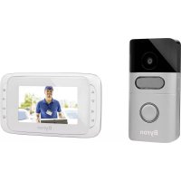
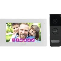
| Product type | Video intercom |
| Brand | Byron |
| Model | DIC24122 |
| Screen size | 7 inches (diagonal) |
| Screen resolution | 800 × 480 pixels |
| Video system | PAL/NTSC |
| Image sensor (outdoor unit) | 1/4" CMOS |
| Viewing angle | Approx. 100° |
| Minimum illumination | 0 Lux (night vision) |
| Power supply | DC 15V, 1A (AC adapter included) |
| Power consumption | 450 ± 200 mA |
| Operating temperature | -10°C to +50°C |
| Operating humidity | 85% RH max |
| Main functions | Videophone, intercom, video recording, photo, door and gate opening (optional) |
| Video storage | microSD card (not included) |
| Photo storage | Internal memory and microSD card |
| Video recording duration | 5 to 30 seconds (adjustable) |
| Number of photos per trigger | 1, 3 or 5 |
| Image settings | Brightness, contrast, saturation |
| Indoor intercom | Communication between two screens (additional screen required) |
| Package contents | Indoor unit, outdoor unit, mounting plates, AC adapter, cables, connection terminals, extra call button, instruction manual, screws and wall plugs |
Frequently Asked Questions - DIC24122 BYRON
User questions about DIC24122 BYRON
0 question about this device. Answer the ones you know or ask your own.
Ask a new question about this device
Download the instructions for your Intercom in PDF format for free! Find your manual DIC24122 - BYRON and take your electronic device back in hand. On this page are published all the documents necessary for the use of your device. DIC24122 by BYRON.
USER MANUAL DIC24122 BYRON
1.1 Installation Safety....6
1.2 Operation Safety 6
2 Parts description 6
2.1 What's in the box....6
2.2 Indoor unit (monitor)....6
2.3 Outdoor unit (doorbell) 7
3 Installation....7
3.1 Fix the mounting plate of the indoor unit (monitor) 7
3.2 Fix the mounting plate of the outdoor unit (doorbell) 7
3.3 Electrical installation 7
3.3.1 Connecting the terminal blocks (Indoor and Outdoor unit) 7
3.3.2 Mount the indoor units and outdoor unit 8
3.3.3 Connecting an additional monitor (not included) 8
3.3.4 Connecting the AC power 8
3.3.5 Connecting a door lock (not included) 8
3.3.6 Connecting a gate opener (not included)....9
4 Replace call button....9
5 Basic functions....9
Byron Table of Contents
5.1 Answering a call....9
6 Home screen and menus 9
6.1 Monitor menu 9
6.2 Internal intercom....10
6.3 Recording playback menu 10
6.4 Photo menu....10
6.5 Settings menu 10
6.5.1 Select photos or video recordings.... 10
6.5.2 Video duration.... 10
6.5.3 Number of photos 11
6.5.4 Image settings.... 11
6.5.5 Customer service information 11
6.5.6 Formatting MicroSD card\Internal memory 11
6.5.7 Date and time settings 11
6.5.8 Ringtone and volume 11
7 Frequently asked questions 11
8 Specifications 12
9 Environment....13
10 Declaration of Conformity.... 13
1 Safety
- Please read these instructions carefully before installing and using the product.
- Do not cut the power supply cable to extend it; the device (transformer) will not work with a longer cable. Do not plug in the device until all the wiring has been finished.
1.1 INSTALLATION SAFETY
- Keep children and bystanders away while installing the products. Distractions can cause you to lose control.
- Do not overreach when installing this product. Keep proper footing and balance at all times. This enables better control in unexpected situations.
- This product is not a toy. Mount it out of reach of children.
-
Do not operate electrically powered products in explosive atmospheres, such as in the presence of flammable liquids, gases, or dust. Electrically powered products create sparks which may ignite the dust or fumes.
-
The warnings, precautions, and instructions discussed in this instruction manual cannot cover all possible conditions and situations that may occur. It must be understood by the operator that common sense and caution are factors which cannot be built into this product, but must be supplied by the operator.
-
Do not expose the Power Adapter of this product to rain or wet conditions. Water entering the Power Adapter will increase the risk of electric shock.
- Do not abuse the Power Cord. Never use the cord for unplugging the plug from the outlet. Keep cord away from heat, oil, sharp edges or moving parts. Damaged or entangled cords increase the risk of electric shock.
- The adapter must match the outlet. Never modify the plug in any way. Unmodified plugs and matching outlets will reduce risk of electric shock.
2 Parts description
2.1 WHAT'S IN THE BOX
- Indoor unit (monitor)
- Outdoor unit (doorbell)
- Mounting plate outdoor unit (doorbell)
- Mounting plates monitors
- AC adapter
- Additional call button for outdoor unit
- Cables
- Terminal blocks
- Instruction manual
- Screws and plugs
2.2 INDOOR UNIT (MONITOR)
-
Microphone
-
Home button
-
Touchscreen
- MicroSD card slot
- Microphone
- Camera
- Speaker
- Call button (replaceable, extra button included)
- Call button 2 (replaceable, extra button included)
- Lock release time switch (On the back of the unit)
3 Installation
3.1 FIX THE MOUNTING PLATE OF THE INDOOR UNIT (MONITOR)
To mount the monitor, you will need the following tools:
√ A suitable screwdriver for the included screws.
√ A drill and suitable drill bit for the included screw plugs.
A. Position the provided mounting plate where desired.
B. Mark the screw positions with a pen.
C. Drill the necessary holes.
D. Insert the plugs.
E. Pull the required cables through the mounting plate.
F. Fasten the mounting plate with the screws.
G. Repeat steps a-f for the second monitor.
3.2 FIX THE MOUNTING PLATE OF THE OUTDOOR UNIT (DOORBELL)
To mount the outdoor unit, you will need the following tools:
√ A suitable screwdriver for the included screws.
√ A drill and suitable drill bit for the included screw plugs.
A. Position the provided mounting plate where desired.
B. Mark the screw positions with a pen.
C. Drill the necessary holes.
D. Insert the plugs.
E. Use a knife or sharp object to puncture the cable gland.
F. Pull the required cables through the cable gland.
G. Fasten the mounting plate with the screws.
3.3 ELECTRICAL INSTALLATION
3.3.1 Connecting the terminal blocks (Indoor and Outdoor unit)
There are three terminal blocks included. The GREEN (outdoor unit) and ORANGE (AC power) terminal blocks are always required. In case you wish to connect an additional monitor a BLUE terminal block is also available.
To connect the terminal blocks, you will need the following tool:
√ A small flat head screw driver.
A. GREEN terminal block: Loosen the terminal screws.
B. With the terminal facing you, insert the black wire on the left and the red wire on the right.
C. Fasten the terminal screws.
D. Connect the terminal block(s) to the indoor unit (monitor).
E. Loosen the terminal screws on the outdoor unit (doorbell). (See sticker on the outdoor unit.)
F. Insert the wires coming from the GREEN terminal block into the screw terminal on the outdoor unit (doorbell). Indoor unit (Monitor) 1 or 2.
G. Repeat steps a-f to connect the second monitor.
3.3.2 Mount the indoor units and outdoor unit
√ A suitable screwdriver for the included screws.
A. Attach the indoor units and outdoor unit to the mounting plates.
B. Fasten the screw at the bottom of the outdoor unit.
3.3.3 Connecting an additional monitor (not included)
In case you wish to connect an additional monitor to an existing monitor, a BLUE terminal block is available. This monitor acts as a repeater to one of the main monitors.
To connect the terminal blocks, you will need the following tool: √ A small flat head screw driver.
A. BLUE terminal block: Loosen the terminal screws.
B. With the terminal facing you, insert the black wire on the left and the red wire on the right.
C. Fasten the terminal screws.
D. Connect the terminal block to the monitor. (See sticker on the monitor for position)
E. Repeat steps a-d to fasten an identical terminal block to the other end of the cable and connecting it to the additional monitor.
3.3.4 Connecting the AC power
To connect the AC terminal blocks, you will need the following tool: √ A small flat head screw driver.
A. ORANGE terminal block: Loosen the terminal screws.
B. With the terminal facing you: Insert the (-) wire on the left and the (+) wire on the right.
C. Fasten the terminal screws.
D. Connect the terminal block(s) to the monitor.
3.3.5 Connecting a door lock (not included)
It is possible to connect a lock to the outdoor unit that can be opened, using the monitor. Door locks are sold separately. Article no: DB5005 & DB5005L
To connect the door lock, you will need the following tool: √ A small flat head screw driver.
A. On the outdoor unit: Loosen the terminal screws. (see sticker on the outdoor unit for position)
B. Insert the wires (any order)
C. Fasten the terminal screws.
D. Set the lock release time by setting switch no 1 on the doorbell. This will set whether the lock will open for 1 or 4-7 seconds after opening the lock on the monitor.
E. On the lock: Loosen the 2 terminal screws. (See the manual provided with your door lock.)
F. Insert the wires (any order)
G. Fasten the terminal screws.
3.3.6 Connecting a gate opener (not included)
It is possible to connect a gate opener to the outdoor unit that can be opened using the monitor.
To connect the gate opener, you will need the following tool:
√ A small flat head screw driver.
A. On the outdoor unit: Loosen the terminal screws. (see sticker on the outdoor unit for position)
B. Insert the wires. (see sticker on the outdoor unit for position) It is important that the + and - wires are in the correct position.
A. Fasten the terminal screws.
B. On the gate opener: (See the manual provided with your gate opener.)
4 Replace call button
An extra call button is added to the box. This button is marked with a bell symbol to avoid confusion on where to push.
The original call button (without marking) on the outdoor unit is replaceable.
Pull the call button with force to remove it.
You can use the blank button for engraving your name.
5 Basic functions
5.1 ANSWERING A CALL
When the doorbell rings, you can:
A. Press the gate button to open the gate (optional).
B. Press the lock button to open the door (optional).
C. Press the camera button to make a video or take a picture.
D. Press the talk button to talk to your visitor.
6 Home screen and menus
- Press the home button on the monitor to open the home screen. The screen will turn on, and you can view the home screen.
The home screen allows you to access the following menus:
- Time/date
- Monitor menu
- Intercom menu
- Playback recordings menu
- Photo menu
- Settings menu
- Power off
6.1 MONITOR MENU
√ Open the monitor menu from the home screen to check the live footage from the doorbell camera.
A. Press the gate icon to open your gate.
B. Press the lock icon to open your lock.
C. Press the photo icon to take a snap shot.
D. Press the speaker icon to communicate.
⇒ Press the home button to exit the menu and go back to the home screen.
6.2 INTERNAL INTERCOM
√ You need an additional monitor to use this function.
A. Open the intercom menu from the home screen on one of your monitors.
→ The other monitor will start chiming.
B. Press the answer icon in the top corner of the screen of the second monitor to accept the call.
→ You will now be able to talk to another person from one monitor to the other.
C. Press the end call icon in the top corner on one of the monitors to end the call.
√ You have made recordings.
A. Open the playback menu from the homescreen.
B. Use the onscreen arrow buttons to scroll through your recordings.
C. Use the onscreen controls to review or delete your recorded footage.
6.4 PHOTO MENU
You have taken photos
A. Open the photo menu from the home screen.
B. Use the onscreen arrow buttons to scroll through your saved photos.
C. Use the onscreen controls to review or delete your saved photos.
6.5 SETTINGS MENU
A. Select photos or video recordings
B. Video duration
C. Number of photos
D. Image settings
E. Customer service information
F. Formatting MicroSD card / Internal memory
G. Date and time settings
H. Ringtone and volume settings
6.5.1 Select photos or video recordings
You can choose if your intercom takes photos or video recordings of your visitors.
√ Make sure to have a MicroSD card installed if selecting video recording.
A. Tap on the video icon to select video recordings
B. Tap on the photo icon to select photos.
6.5.2 Video duration
You can select video recording duration. The video starts recording when the doorbell is activated.
√ Video must be selected in the settings menu.
A. Press the button with the desired duration, 5-30 seconds.
6.5.3 Number of photos
You can select amount of photos recorded. The photos are taken when the doorbell is activated.
√ Photos must be selected in the settings menu.
A. Press the button with the desired amount, 1, 3 or 5 photos.
6.5.4 Image settings
The image can be adjusted using the arrows. The settings include:
- Brightness
- Contrast
• Color saturation
6.5.5 Customer service information
At smartwares, we care about our customers and that the products work as intended. Please contact us if you run into any issues. You can also check out our YouTube videos by scanning the QR code below with your phone!

6.5.6 Formatting MicroSD card\Internal memory
The internal memory is used to store photos and is formatted separately from videos that can only be stored on a MicroSD card (not included).
A. Press the photo icon and confirm to format the internal memory
B. Press the video icon and confirm to format the MicroSD card (not included).
6.5.7 Date and time settings
A. Select the desired field to change.
B. Press the arrow keys up or down until the desired value is shown.
6.5.8 Ringtone and volume
The ringtone melody and volume can be adjusted using the arrow keys. The settings include:
• Volume
- Ringtone melody
7 Frequently asked questions
Problem Solution
- Monitor does not switch on. • Make sure that the monitor is connected to the power source.
- Do not use extension cords, as the voltage might not be sufficient to power on the device.
- Monitor is switched on but no image is displayed.
- Check the wire connections between the outdoor unit and the monitor (including the correct polarity).
• The picture quality is not good. - Adjust brightness and contrast in settings menu.
- Make sure there is no direct light source pointed at the monitor.
- The volume is too low. • Adjust the volume
- Connected gate opener does not work.
- Test the installation and the 12 V relay using wired control. Refer to the instruction manual of the gate opener.
- Connected gate opener and electric strike does not work.
- Use suitable accessories with 12 V, 500 mA specification. Only install lock having a mechanical storage system.
• Video and audio signal is too weak or with interference
• There is no sound coming from the outdoor unit.
- The monitor is installed too close to other electronic devices. Move other electrical devices away.
- Please check the distance between indoor unit with outdoor unit, and also check the thickness of the cables used,
• The microphone might be obstructed or stained. Clean it carefully with a soft moistened cloth.
8 Specifications Monitor
Screen size 7"(Diagonal) inch
Color Configuration R.G.B.delta
Video System PAL/NTSC
Effective Pixels 800X3(RGB)X480
Consumption Current 450±200mA
Operation Temperature -10°C \~ +50°C
Operation Humidity 85%(Max)
Supply Voltage DC 15V 1A
Doorbell
Imaging Sensor Type 1/4"CMOS
View Angle about 100o
Minimum Illumination 0Lux
Night vision distance 0.5 \~ 1m
Operating Temperature -10°C \~ +50°C
Operating Humidity ≤85%RH

EN
9 Environment

This appliance should not be put into the domestic garbage at the end of its durability, but must be offered at a central point for the recycling of electric and electronic domestic appliances. This symbol on the appliance, instruction manual and packaging puts your attention to this important issue. The materials used in this appliance can be recycled. By recycling of used domestic appliances you contribute an important push to the protection of our environment. Ask your local authorities for information regarding the point of recollection.
Support
You can find all available information and spare parts at www.chbyron.eu
Please read manual before use, and store it carefully for future use and maintenance.
You can also check out our YouTube videos by scanning the QR code below with your phone!
10 Declaration of Conformity
Hereby, Smartwares Europe declares that the radio equipment type DIC-24122 is in compliance with Directive 2014/53/EU
The full text of the EU declaration of conformity is available at the following internet address: www.chbyron.eu/doc
Inhalt
1 Sicherheit .... 17
6.5.5 Informations service client
8 Specifications Monitor
3 Installation....89
System wideo PAL/NTSC