MM 12 - Multimeter BENNING - Free user manual and instructions
Find the device manual for free MM 12 BENNING in PDF.
Pick your language and provide your email: we'll send you a specifically translated version.
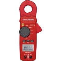
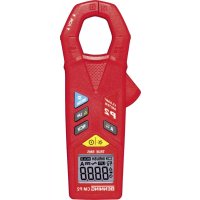
| Product Type | Portable Digital Multimeter |
| Brand | BENNING |
| Model | MM 12 |
| Dimensions (L x W x H) | Approx. 150 x 70 x 30 mm |
| Weight | Approx. 200 g (with battery) |
| Power Supply | 1 9V battery (type 6LR61/6F22) |
| Display | Digital LCD screen, 4000 counts |
| Auto-ranging | Yes |
| DC Voltage | 400 mV to 600 V (accuracy ±0.8%) |
| AC Voltage | 400 mV to 600 V (accuracy ±1.2%) |
| DC Current | 400 µA to 10 A |
| AC Current | 400 µA to 10 A |
| Resistance | 400 Ω to 40 MΩ |
| Capacitance | 4 nF to 100 µF |
| Diode Test | Yes |
| Continuity Test | Yes (audible) |
| Safety | CAT II 600 V / CAT III 300 V |
| Maintenance and Cleaning | Wipe with a dry cloth; do not use solvents |
| Supplied Accessories | Batteries, test leads, user manual |
| Repairability | Spare parts available via BENNING after-sales service |
| Warranty | 2 years |
Frequently Asked Questions - MM 12 BENNING
How to measure DC voltage with the BENNING MM 12?
Turn the selector to the V⎓ position. Connect the leads: red lead to the 'VΩmA' jack and black lead to 'COM'. Place the test probes on the measuring points. Read the value on the LCD screen.
How to measure AC voltage?
Turn the selector to the V~ position. Connect the leads as for DC voltage. Ensure you follow the safety instructions for high voltages.
How to measure electric current?
Turn the selector to the appropriate current range (A⎓ or A~). Connect the red lead to the '10A' jack for currents up to 10 A, or to 'VΩmA' for low currents. The circuit must be open and the multimeter inserted in series.
How to test continuity of a circuit?
Turn the selector to the ️ (continuity) position. Connect the leads as usual. If the resistance is below approximately 30 Ω, a beep sounds.
How to test a diode?
Turn the selector to the (diode) position. Connect the red probe to the anode and the black probe to the cathode. The display shows the forward voltage. Reversing the probes gives 'OL' if the diode is good.
What does 'OL' display mean?
'OL' means 'Overload' (exceeding the measurement range). This indicates that the measured value exceeds the selected range's capacity. Switch to a higher range or check your circuit.
How to replace the multimeter battery?
Turn off the device and remove the test leads. Open the battery compartment at the back. Replace the used 9V battery with a new one, observing polarity. Close the cover.
What safety precautions should be observed?
Never exceed the indicated maximum voltages or currents. Use appropriate leads. Do not measure voltages in resistance or continuity mode. Disconnect the leads before changing the battery.
How to clean the multimeter?
Clean the device with a soft, dry cloth. Never use chemicals or abrasives. Make sure no liquid enters the interior.
Where to find spare parts or after-sales service?
Contact BENNING after-sales service via the official website or an authorized dealer. Leads and batteries are available commercially. For any repairs, contact a professional.
User questions about MM 12 BENNING
0 question about this device. Answer the ones you know or ask your own.
Ask a new question about this device
No questions yet. Be the first to ask one.
Download the instructions for your Multimeter in PDF format for free! Find your manual MM 12 - BENNING and take your electronic device back in hand. On this page are published all the documents necessary for the use of your device. MM 12 by BENNING.