TB 312 - Multimeter Testboy - Free user manual and instructions
Find the device manual for free TB 312 Testboy in PDF.
| Product type | Digital multimeter |
| Brand | Testboy |
| Model | TB 312 |
| Dimensions (L x W x H) | 210 x 105 x 45 mm |
| Weight (with batteries) | 560 g |
| Power supply | 6 AAA 1.5 V batteries |
| Display | LCD 40 mm, 59999 counts (4 3/4 digits) with bar graph |
| Measurement category | CAT III 1000 V |
| Maximum voltages | 1000 V DC/AC between connectors and ground |
| Fuses | F 500 mA/1000 V (fast) and F 10 A/1000 V (fast) |
| Measurement functions | DC/AC voltage, DC/AC current, resistance, capacitance, frequency, duty cycle, diode test, continuity test, relative measurement, dBm |
| DC voltage range | 50 mV to 1000 V |
| AC voltage range | 50 mV to 1000 V (40 Hz – 20 kHz) |
| DC current range | 500 µA to 10 A |
| AC current range | 500 µA to 10 A (40 Hz – 20 kHz) |
| Resistance range | 500 Ω to 50 MΩ |
| Capacitance range | 50 nF to 5000 µF |
| Frequency range | 5 Hz to 2 MHz (logic), 5 Hz to 60 kHz (linear) |
| PC interface | USB (optical coupling) |
| Included software | Yes (CD) |
| Operating temperature | 0 °C to 50 °C, RH < 80 % |
| Storage temperature | -20 °C to 60 °C, RH < 80 % |
| Maximum altitude | 2000 m |
| Maintenance | Clean with damp cloth and mild detergent; batteries and fuses replaceable |
| Safety | Double insulation, complies with CE standards, surge protection |
Frequently Asked Questions - TB 312 Testboy
User questions about TB 312 Testboy
0 question about this device. Answer the ones you know or ask your own.
Ask a new question about this device
Download the instructions for your Multimeter in PDF format for free! Find your manual TB 312 - Testboy and take your electronic device back in hand. On this page are published all the documents necessary for the use of your device. TB 312 by Testboy.
USER MANUAL TB 312 Testboy
text_image
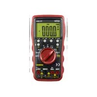
AUTO POWER OFF AC/AC+DC TRUE RMS WAKE MAX/MIN Hz LIGHT SELECT dbm- RANGE RIS. USB HOLD MHz % mV V V dB m A mA mA COM 10A MAX FUSED 300mA FUSED 100V- CAT II ΩTestboy® TB 312
Version 1.6
de Testboy® TB 312 3
Bedienungsanleitung
en Testboy® TB 312 27
Operating Instructions
fr Testboy® TB 312 51
Manuel d'utilisation
(es) Testboy® TB 312 75
Manual de instrucciones
pt Testboy® TB 312 99
Manual de instruções
Testboy® TB 312 123
Bruksanvisning
fi Testboy® TB 312 147
Käyttöohje
tr Testboy® TB 312 171
Kullanım kılavuzu
Testboy® TB 312 195
Инструкция по использованию
Inhaltsverzeichnis
text_image
Welcome to the InstallShield Wizard for TB312 Digital Multimeter Choose your Installation language. German Englishtext_image
MultiMeter - InstallShield Wizard Welcome to the InstallShield Wizard for MultiMeter The InstallShield(R) Wizard will allow you to modify, repair, or remove MultiMeter. To continue, click Next. < Back Next > Canceltext_image
MultiMeter - InstallShield Wizard InstallShield Wizard Completed The InstallShield Wizard has successfully installed MultiMeter. Click Finish to exit the wizard.Table of Contents 27
Notes 28
General safety notes 28
Safety notes 30
Operation 33
Introduction 33
Switches, buttons and jacks description 35
Display 36
DC voltage measurement / V= 38
AC voltage measurement / V\~ 39
DC current measurement / A= 40
AC current measurement / A\~ 41
Capacitance measurement / F* 42
Resistance measurement / Ω 42
Diode test 43
Continuity test 43
Frequency 44
Duty cycle 44
Relative value measurement 44
Maintenance 45
Cleaning 45
Changing the batteries 45
Changing the fuse 45
PC software 46
Technical data 50
Notes
General safety notes

WARNING
Unauthorised modification and/or changes to the instrument are not permitted, for reasons of safety and approval (CE). In order to ensure safe and reliable operation using the instrument, you must always observe the safety instructions, warnings and the information contained in the section "Intended use".

WARNING
Please observe the following information before using the instrument:
Do not operate the instrument anywhere near electrical welders, induction heaters or other electromagnetic fields.
Further to abrupt temperature fluctuation, the instrument must be allowed to adjust to the new ambient temperature for approx. 30 minutes before using it, in order to stabilise the IR sensor.
Do not expose the instrument to high temperatures for a long period of time.
Avoid dusty and humid environments.
Measuring instruments and their accessories are not toys, and must be kept out of the reach of children!
In industrial facilities, the accident prevention regulations for electrical systems and equipment, established by the employer's liability insurance association, must be observed.

Please observe the five safety rules:
1 Disconnect
2 Ensure that the instrument cannot be switched back on again
3 Ensure isolation from the power supply (check that there is no voltage on both poles)
4 Earth and short-circuit
5 Cover adjacent live parts
Intended use
The instrument is intended strictly for use in applications described in the operating instructions. Any other usage is considered improper and forbidden, and can result in accidents or the destruction of the instrument. Any such application will result in the immediate expiry of all guarantee and warranty claims on the part of the operator against the manufacturer.

Remove the batteries if the instrument is not in use for a long period of time, in order to protect the instrument from damage.

We assume no liability for damages to property or personal injury caused by improper handling or failure to observe the safety instructions. Any warranty claim expires in such cases. An exclamation mark in a triangle indicates safety notices in the operating instructions. Read the instructions completely before beginning the initial commissioning. This instrument is CE-approved and thus fulfils the required guidelines.
All rights reserved to alter specifications without prior notice
© Testboy GmbH, Germany.
Safety notes

WARNING
Sources of danger are mechanical parts, for example, which can cause serious personal injury.
Objects are also at risk (e.g. damage to the instrument).
WARNING
An electric shock can result in death or serious personal injury, and also functional damage to objects (e.g. damage to the instrument).
Disclaimer

The warranty claim expires in cases of damages caused by failure to observe the instructions! We assume no liability for any resulting damage!
Testboy is not responsible for damage resulting from
| failure to observe the instructions
changes to the product that have not been approved by Testboy or
the use of replacement parts that have not been approved or manufactured by Testboy
the use of alcohol, drugs or medication.
Accuracy of the operating instructions
These operating instructions have been compiled with due care and attention. No guarantee is given that the data, illustrations and drawings are complete or correct. All rights reserved with regard to changes, printing mistakes and errors.
Disposal
Dear Testboy customer: purchasing our product gives you the option of returning the instrument to suitable collection points for waste electrical equipment at the end of its lifespan.

The WEEE directive regulates the return and recycling of electrical appliances. Manufacturers of electrical appliances are obliged to take back and recycle all electrical appliances free of charge. Electrical devices may then no longer be disposed of through conventional waste disposal channels. Electrical appliances must be recycled and disposed of separately. All equipment subject to this directive is marked with this logo.
Disposal of used batteries

As an end user, you are legally obliged (battery law) to return all used batteries; disposal with normal domestic waste is prohibited!
Batteries containing contaminant material are labelled with adjacent symbols indicating the prohibition of disposal with normal domestic waste.
The abbreviations used for the respective heavy metals are:
Cd = cadmium, Hg = mercury, Pb = lead.
You can return your used batteries free of charge to collection points in your community or anywhere where batteries are sold!
Certificate of quality
All activities and processes carried out within Testboy GmbH relating to quality are monitored permanently within the framework of a Quality Management System. Furthermore, Testboy GmbH confirms that the testing equipment and instruments used during the calibration process are subject to a permanent inspection process.
Declaration of conformity
The product conforms to the most recent directives. For more information, go to www.testboy.de
Operation
Introduction
The Testboy ^® TB 312 is a universal multimeter. This measuring instrument has been manufactured to the latest safety specifications, and guarantees safe and reliable operation. The multimeter is a valuable aid for all standard measurement tasks in trade and industry as well as for electronics hobbyists.
Scope of delivery
Multimeter TB 312
Safety test leads (CAT III 1000 V)
Operating instructions
PC software (CD)
USB cable
Safety precautions
The TB 312 left the factory with its safety features in perfect working order. In order to maintain this condition, the user must observe the safety notes contained in this manual.

Caution!
Use only the enclosed safety test leads or equivalent test leads that meet the correct measurement category CAT III 1000 V.
In order to avoid risk of electric shock, you must observe the specified precautions when working with voltages greater than 70 V (35 V) DC or 33 V (16 V) eff AC. These values represent the limits of safe-to-touch voltages in accordance with DIN VDE. (Values given in brackets apply to medical or agricultural areas, for example)
Before taking each measurement, ensure that the test lead and the test instrument are in perfect working order
The test leads and test probes must only be handled using the grips provided. Avoid touching the test probes under any circumstances.

The test instrument must only be used for the measuring ranges specified.
According to the standard EN 61010-1, the following measurement categories are defined:
Measurement category CAT II
Measurements on circuits that are directly electrically connected to the network, via plugs in the home, office and laboratory.
Measurement category CAT III
Measurements on building installations: fixed consumer units, distributor connection, equipment fitted permanently to the distributor
Measurement category CAT IV
Measurements at the source of the low voltage installation: meters, primary surge protection, mains connection.
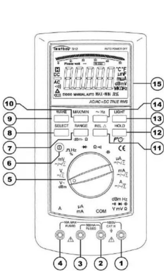
Switches, buttons and jacks description
text_image
testbay® 312 AUTO POWER OFF Please wait ... 30 40 50 DC AC Δ ST1000 MANUAL AUTO MAX-NIN JL% AC/AC+DC TRUE RMS WAKE MAX/MIN ~ Hz LIGHT SELECT RANGE REL Δ HOLD dBm-Ω Ω-1 CE mA =/-√2 mA =/-√2 A V~ dBm μA mA COM dBm Hz +0 -1 V mV Ω 10 9 8 7 6 5 4 3 2 1| (1)V / Ω/dBm/Hzjack | Red test lead for all types of signals supported by the instrument. |
| (2) COMjack | Black test lead for all types of signals supported by the instrument. |
| (3) mA jack | For current measurements up to 500 mA |
| (4) 10 A jack (left) | The 10 A jack must be used for current measurements above 500 mA. |
| (5) Measuring function selector switch | Use the rotary selector switch to select the various basic measurement modes. |
| (6) POWERSwitch | The device is turned on and off via a "POWER" push-button switch. |
| (7) RANGebutton | Manual measuring range selection |
| (8) SELECTbutton (yellow) | Measurement type selection (yellow lettering) |
| (9) WAKE button | Wakes the instrument from sleep mode |
| (10) MAX/MINbutton | Measured value display MAX, MIN and MAX-MIN value |
| (11) REL button | Switch-over to relative value display |
| (12) HOLD button | Measured value storage |
| (13) LIGHT button | Backlighting |
| (14) ~ HZ button | Frequency measurement during voltage and current measurement |
| (15) LCD display | See below |
Display

text_image
Please wait ... PCLINK °C °F μnF mμA dB mV MKΩHz 51000 MANUAL AUTO MAX-MIN Π% ⑥ ⑤ ④ ③ ②| Number | Icon | Function |
| 1 | °C °F | Temperature measurement °C or °F |
| 1 | mnF | Capacitance measurement nF or mF |
| 1 | mμA | Current measurement μA, mA or A |
| 1 | dBmV | dBm or voltage measurement mV or V |
| 1 | MKΩHz | Resistance measurement Ω, KΩ or MΩAlso frequency measurement Hz, KHz, MHz |
| 2 | Ω % | Duty cycle in % |
| 3 | MAX-MIN | Measured value recording MAX maximum, MIN minimum, MAX-MIN differentiated value |
| 4 | AUTO | Automatic measuring range selection |
| 5 | MANUAL | Manual measuring range selection |
| 6 | 51000 | Measured value display 5, 50, 500 and 1000, 5000, etc. |
| 7 | Battery icon indicating low battery | |
| 8 | Relative measurement | |
| 9 |  | Continuity measurement |
| 10 |  | Alternating voltage or alternating current measurement |
| 11 |  | Negative measured value |
| 12 |  | Direct voltage or direct current |
| 13 |  | Measured value storage |
| 14 | Please Wait ... | Pause indicator when measuring capacitances of 50 μF - 5000 μF in the automatic measuring range, in order to maintain accuracy until the capacitor has been completely discharged |
| 15 | 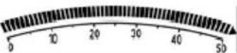 | Analogue bargraph display |
| 16 | PCLINK | USB connection |
| 17 |  | Measured value display |
DC voltage measurement / V=
Set the appropriate range (mV or V) using the selector switch. Connect the black test lead to the “COM” jack and the red test lead to the red V / mV / Ω jack. Connect test leads to the test specimen. Read off measurement result from the display. The voltage polarity is also displayed.
DC voltage
| Measuring range | Resolution | Accuracy |
| 50 mV | 0.001 mV | ± 0.03 % of meas. val. + 10 digits |
| 500 mV | 0.01 mV | ± 0.03 % of meas. val.+ 6 digits |
| 5 V | 0.1 mV | |
| 50 V | 1 mV | |
| 500 V | 10 mV | |
| 1000 V | 0.1 V |
-Input resistance: 10 MΩ.
-Max. input voltage: 1000 V DC.
Press the SELECT button to switch between DC, AC and AC+DC measurement methods.
AC voltage measurement / V\~
Set the appropriate range (mV or V\~) using the selector switch. Press the SELECT button to set to AC. Connect the black test lead to the "COM" jack and the red test lead to the red V / mV / Ω jack. Connect test leads to the test specimen. Read off measurement result from the display.
AC voltage
| Measuring range | Resolution | Accuracy | ||
| 40 Hz – 1 kHz | 1 kHz – 10 kHz | 10 kHz – 20 kHz | ||
| 50 mV | 0.001 mV | ± 0.5 % of meas. val. + 40 digits | ± 1 % of meas. val. + 40 digits | ± 2.5 % of meas. val. + 40 digits |
| 500 mV | 0.01 mV | |||
| 5 V | 0.1 mV | |||
| 50 V | 1 mV | |||
| 500 V | 10 mV | not specified | ||
| 1000 V | 0.1 V | not specified | not specified | |
Accuracy specified only valid for 10 % to 100 % of the measuring range.
-Input resistance: 10 MΩ.
-Max. input voltage: 1000 V AC RMS, frequency range: 40 Hz-20 kHz.
Press the SELECT button to switch between the AC and dBm measuring range.
DC current measurement / A=
Set the appropriate range ( A, mA or A) using the selector switch. Connect the black test lead to the “COM” jack and the red test lead to the mA or 10 A jack. Connect test leads to the test specimen. Read off measurement result from the display. The current direction is indicated by the sign.

You must use the “10 A” jack when measuring currents above 500 mA!
Direct current
| Measuring range | Resolution | Accuracy |
| 500 μA | 0.01 μA | ± 0.15 % of meas. val.+ 15 digits |
| 5000 μA | 0.1 μA | |
| 5 mA | 1 μA | |
| 50 mA | 10 μA | |
| 500 mA | 0.1 mA | ± 0.5 % of meas. val.+ 10 digits |
| 10 A* | 1 mA |
- 500 mA range is protected by a F 500 mA / 1000 V fuse.
- 10 A range is protected by a F 10 A / 1000 V fuse.
- in the 10 A range observe the maximum duty cycles!

* Following measurement, which should take a max. 10 seconds, allow the instrument to cool down for 15 minutes to protect against overheating.
Press the SELECT button to switch between DC, AC and AC+DC measurement methods.
AC current measurement / A\~
Set the appropriate range using the selector switch. Connect the black test lead to the "COM" jack and the red test lead to the mA or 10 A jack. Connect test leads to the test specimen. Read off measurement result from the display.

You must use the “10 A” jack when measuring currents above 500 mA!
Alternating current
| Measuring range | Resolution | Accuracy | ||
| 40 Hz – 1 kHz | 1 kHz – 10 kHz | 10 kHz – 20 kHz | ||
| 500 μA | 0.01 μA | ± 0.75 % of meas. val.+ 20 digits | ± 1 % of meas. val.+ 20 digits | ± 1.2 % of meas. val.+ 5 digits |
| 5000 μA | 0.1 μA | ± 0.75 % of meas. val.+ 10 digits | ± 1 % of meas. val.+ 10 digits | ± 1.2 % of meas. val.+ 5 digits |
| 50 mA | 1 μA | ± 0.75 % of meas. val.+ 20 digits | ± 1 % of meas. val.+ 20 digits | ± 1.2 % of meas. val.+ 5 digits |
| 500 mA | 10 μA | ± 0.75 % of meas. val.+ 10 digits | ± 1 % of meas. val.+ 10 digits | ± 1.2 % of meas. val.+ 5 digits |
| 5 A | 0.1 mA | ± 0.75 % of meas. val.+ 20 digits | ± 1.5 % of meas. val.+ 20 digits | ± 1.2 % of meas. val.+ 5 digits |
| 10 A* | 1 mA | ± 1 % of meas. val.+ 10 digits | ± 1.5 % of meas. val.+ 10 digits | not specified |
Accuracy specified only valid for 10% - 100% of the measuring range.
- 500 mA range is protected by a F 500 mA / 1000 V fuse.
- 10 A range is protected by a F 10 A / 1000 V fuse.
- in the 10 A range observe the maximum duty cycles!
- Frequency range: 40 – 20000 Hz.

* Following measurement, which should take a max. 10 seconds, allow the instrument to cool down for 15 minutes to protect against overheating.
Press the SELECT button to switch between DC, AC and AC+DC measurement methods.
Capacitance measurement / F\*
Set the appropriate range using the selector switch. Connect the black test lead to the "COM" jack and the red test lead to the V / mV / Ω jack. Connect test leads to the test specimen. Read off measurement result from the display.
| Measuring range | Resolution | Accuracy |
| 50 nF | 0.01 nF | ± 1 % + 5 digits |
| 500 nF | 0.1 nF | |
| 5 μF | 1 nF | |
| 50 μF | 10 nF | |
| 500 μF | 0.1 μF | ± 2 % + 5 digits |
| 5000 μF | 1 μF |
Input impedance: 180 kΩ, test voltage: 1,2 V, test current: 2.5 mA

\*Discharge the capacitors before every measurement!
Resistance measurement / Ω
Set the appropriate range using the selector switch. Connect the black test lead to the "COM" jack and the red test lead to the V / mV / Ω jack. Connect test leads to the test specimen. Read off measurement result from the display.
| Measuring range | Resolution | Accuracy |
| 500 Ω | 0.01 Ω | ± 0.1 % + 10 digits |
| 5 kΩ | 0.1 Ω | ± 0.1 % + 5 digits |
| 50 kΩ | 1 Ω | |
| 500 kΩ | 10 Ω | |
| 5 MΩ | 100 Ω | ± 0.1 % + 10 digits |
| 50 MΩ | 1 kΩ | ± 0.5 % + 10 digits |
Input impedance: 10 MΩ, test voltage: 3 V, test current: 2 mA.
Diode test
Set to “using the selector switch. Connect the black test lead to the “COM” jack and the red test lead to the V / mV / Ω jack. Connect test leads to the test specimen. Red test lead = anode, black test lead = cathode. The forward voltage drop is displayed.
| Measuring range | Resolution | Display |
| 0.1 mV | Forward voltage |
-Forward current: approx. 0.7 mA, flyback voltage: approx. 2.5 V.
Continuity test
Set to “Ω / °)”)” using the selector switch. Switch to continuity testing using the SELECT button. Connect the black test lead to the “COM” jack and the red test lead to the V / mV / Ω jack. Connect test leads to the test circuit. A signal is emitted if a resistance under 60 Ω is measured.

Important: Ensure isolation from the power supply and discharge capacitors in the circuit to be measured.
| Measuring range | Function |
| ○)) | The integrated buzzer signals continuity of up to 60 Ω |
Frequency
Set the selector switch to "Hz". Connect the black test lead to the "COM" jack and the red test lead to the V / mV / Ω jack. Connect test leads to the test circuit. Read off measurement result from the display.
| Measuring range | Resolution | Accuracy |
| Logic frequency (2.5 ~ 5 Vp) | ||
| 5 Hz ~ 2 MHz | 0.001 Hz | ± 0.006 % + 4 digits |
| Linear frequency (500 mV ~ 1000 V, only in the AC measuring range!) | ||
| 5 Hz ~ 60 kHz | 0.001 Hz | ± 0.006 % + 4 digits |
- Input impedance: 3 kΩ
Duty cycle
Set the selector switch to "Hz". Press the SELECT button to switch to the duty cycle measurement range. Connect the black test lead to the "COM" jack and the red test lead to the V / mV / Ω jack. Connect test leads to the test circuit. Read off measurement result from the display.
| Measuring range | Resolution | Accuracy |
| Duty cycle (2.5 ~ 5 Vp at 5 Hz ~ 60 kHz) | ||
| 5 % ~ 95 % | 0.01 % | ± 2 % + 5 digits |
- Input impedance: 3 kΩ
Relative value measurement
Press the “REL” button to enable the relative value measurement method. Pressing the button retains the last measured or displayed value and deducts the subsequent value. The “REL” button can also be used to compensate for test lead resistance.
Maintenance
The instrument does not require special maintenance when used as specified in these operating instructions.
Cleaning
Use a damp cloth and mild household detergent to clean the instrument should it become soiled through daily use. Never use aggressive cleaning agents or solvents to clean the instrument.
Changing the batteries
Change the batteries when the battery icon is displayed. Remove the test leads from the instrument before changing the batteries!
Remove the two screws on the rear of the instrument below the fold-down pedestal, open the battery compartment and remove the spent batteries. Insert new batteries (6 x 1.5 V AAA Micro). Ensure that the polarity is correct. Replace battery compartment and screw tight.

Only use the batteries specified!
Batteries must not be disposed of with normal domestic waste!
Observe the statutory regulations pertaining to disposal!
Changing the fuse
When you need to change the fuse, first remove the test leads from the instrument and remove the battery compartment's two screws on the rear behind the fold-down pedestal. Carefully remove the battery compartment lid, lift off the relevant protective cap of the fuse that is to be changed and replace the defective fuse with one of the same sort (F 10 A / 1000 V or F 500 mA / 1000 V fuse). Replace the protective cap and retighten the screws of the battery compartment.

Only use fuses with the values specified!
PC software
Open up the contents of the CD in your PC's Explorer and run the Setup.exe.
The following drop-down menu appears:
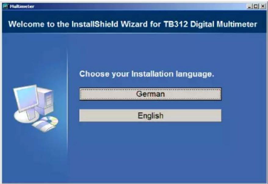
text_image
Welcome to the InstallShield Wizard for TB312 Digital Multimeter Choose your Installation language. German EnglishClick on the relevant button for the language.
After unpacking the installation files, the InstallShield Wizard appears:
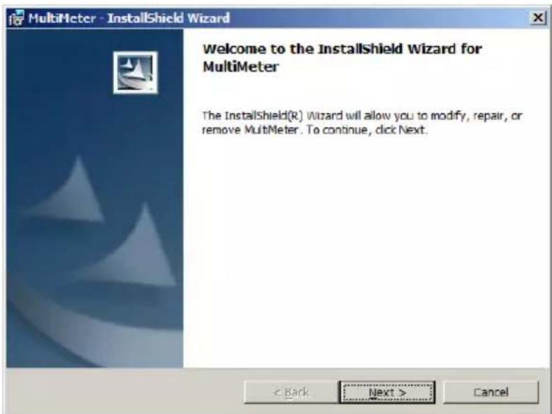
text_image
MultiMeter - InstallShield Wizard Welcome to the InstallShield Wizard for MultiMeter The InstallShield(R) Wizard will allow you to modify, repair, or remove MultiMeter. To continue, click Next. < Back Next > CancelClick on “Next”, select the installation directory and click again on “Next” and then on “Install”, and once installation is complete click on “Finish”:
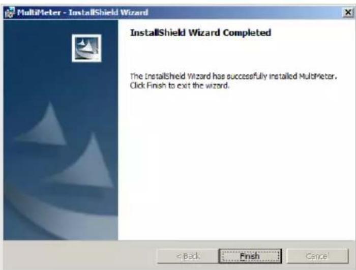
text_image
MultiMeter - InstallShield Wizard InstallShield Wizard Completed The InstallShield Wizard has successfully installed MultiMeter. Click Finish to exit the wizard.Under Programme/Multimeter click on Multimeter.exe or double click on the Multimeter.exe icon on the desktop and the main window appears:
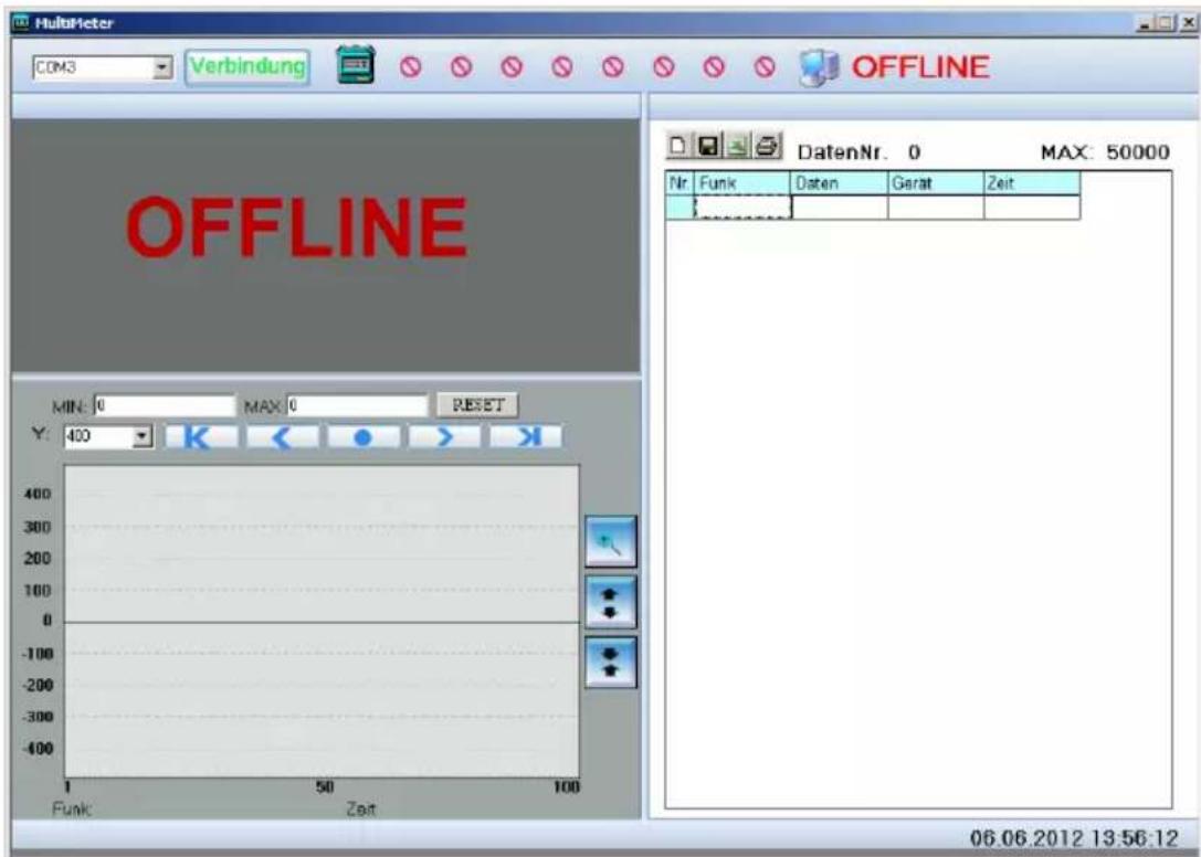
text_image
MultiMeter COM3 Verbindung OFFLINE OFFLINE DatenNr. 0 MAX: 50000 Min: 0 MAX: 0 RESET Y: 400 K < ● > Funk Zeit 06.06.2012 13:56:12Connect the multimeter to a USB port on your PC and hold down the “HOLD” button until “PCLINK” appears on the display.
If the driver is not installed automatically, open the “drivers” folder on the CD
Run the xxxInstaller.exe in the appropriate folder of your operating system.
The following operating systems are supported: Windows 2000, XP, 2003, Vista and Windows 7.
Once the drivers have been installed successfully, a virtual COM port is generated. Please refer to the device manager for the assigned COM port (COM2, COM3, etc).
Configure this COM port in the program's main window (top left) and press "Connection".
Depending on where the rotary selector switch is positioned on the multimeter, you will see a copy of the display in the top left section of the main window, with an XY plot beneath it, and on the right-hand side the data is transferred to a list that you can then easily save, transfer to EXCEL or print.
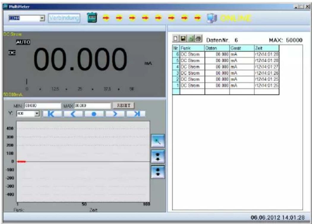
text_image
MultiMeter FCDC Verbindung ONLINE DC Strom AUTO DC 00.000 mA 0 125 25 37.5 60 50.000mA MIN: 09.000 MAX: 00.000 RESET Y: 400 Funk: Zeit DatenNr. 6 MAX: 50000 Nr Funk Daten Gerat Zeit 6 DC Strom 00.000 mA 12x14:01:28 5 DC Strom 00.000 mA 12x14:01:28 4 DC Strom 00.000 mA 12x14:01:27 3 DC Strom 00.000 mA 12x14:01:26 2 DC Strom 00.000 mA 12x14:01:25 1 DC Strom 00.000 mA 12x14:01:25 06.06.2012 14:01:28You can change the view of the XY plot using other tools:
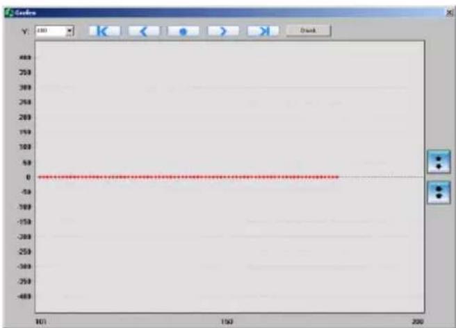
line
| X | Y | | ---- | --- | | 101 | 0 | | 150 | 0 | | 200 | 0 |You can change the time base (X-axis) by using the top arrows, and the Y-axis by using the side arrows. Clicking on “Print” sends the contents of the current display to the printer.
Exit the programme by closing the main window.
Technical data
The accuracy relates to 1 year used at temperatures of 18 °C - 28 °C and 75 % humidity (further annual calibrations are offered).
Max. voltage between the connection socket and ground:
1000 V AC / DC.
| Fuses | F 500 mA 1000 V quick-actingF10 A 1000 V quick-acting |
| Max. operating height | 2000 m above MSL |
| Height of display | 40 mm LCD with bargraph display |
| Display | max 59999 (43⁄4 digits) |
| Polarity indicator | Automatic |
| Over-range indicator | “1” is displayed |
| Sampling rate | Approx. 330 ms. |
| Battery status | Battery icon is displayed |
| Power supply | 6 x 1.5 V AAA Micro |
| Operating temperature | 0 °C to 50 °C RH < 80 % |
| Storage temperature | -20 °C to 60 °C RH < 80 % |
| Dimensions | 210 x 105 x 45 mm |
| Weight | 560 g incl. battery |
| Category | CAT III 1000 V |
| Interface | USB, optical coupling |
Table des matières
Cd = cadmium, Hg = mercure, Pb = plomb.
text_image
Welcome to the InstallShield Wizard for TB312 Digital Multimeter Choose your Installation language. German Englishtext_image
MultiMeter - InstallShield Wizard Welcome to the InstallShield Wizard for MultiMeter The InstallShield(R) Wizard will allow you to modify, repair, or remove MultiMeter. To continue, click Next. < Back Next > Canceltext_image
MultiMeter - InstallShield Wizard InstallShield Wizard Completed The InstallShield Wizard has successfully installed MultiMeter. Click Finish to exit the wizard.text_image
Screenshot of MultiMeter software interface showing DC current display, fault status, and a table for maximum voltage measurement.line
| X | Y | | ---- | --- | | 101 | 0 | | 150 | 0 | | 200 | 0 |text_image
Welcome to the InstallShield Wizard for TB312 Digital Multimeter Choose your Installation language. German Englishtext_image
MultiMeter - InstallShield Wizard Welcome to the InstallShield Wizard for MultiMeter The InstallShield(R) Wizard will allow you to modify, repair, or remove MultiMeter. To continue, click Next. < Back Next > Canceltext_image
MultiMeter - InstallShield Wizard InstallShield Wizard Completed The InstallShield Wizard has successfully installed MultiMeter. Click Finish to exit the wizard.text_image
Screenshot of MultiMeter software interface showing DC Strom display, fault status, and a 50000 timer reading.text_image
Welcome to the InstallShield Wizard for TB312 Digital Multimeter Choose your Installation language. German Englishtext_image
MultiMeter - InstallShield Wizard Welcome to the InstallShield Wizard for MultiMeter The InstallShield(R) Wizard will allow you to modify, repair, or remove MultiMeter. To continue, click Next. < Back Next > Canceltext_image
MultiMeter - InstallShield Wizard InstallShield Wizard Completed The InstallShield Wizard has successfully installed MultiMeter. Click Finish to exit the wizard.line
| X | Y | | ---- | --- | | 10 | 0 | | 150 | 0 | | 200 | 0 |Cd = kadmium, Hg = kvicksilver, Pb = bly.
text_image
Welcome to the InstallShield Wizard for TB312 Digital Multimeter Choose your Installation language. German Englishtext_image
MultiMeter - InstallShield Wizard Welcome to the InstallShield Wizard for MultiMeter The InstallShield(R) Wizard will allow you to modify, repair, or remove MultiMeter. To continue, click Next. < Back Next > Canceltext_image
MultiMeter - InstallShield Wizard InstallShield Wizard Completed The InstallShield Wizard has successfully installed MultiMeter. Click Finish to exit the wizard.line
| X | Y | | ---- | --- | | 101 | 0 | | 150 | 0 | | 200 | 0 |Cd = Kadmium, Hg = Elohopea, Pb = Lyijy.
text_image
Welcome to the InstallShield Wizard for TB312 Digital Multimeter Choose your Installation language. German Englishtext_image
MultiMeter - InstallShield Wizard Welcome to the InstallShield Wizard for MultiMeter The InstallShield(R) Wizard will allow you to modify, repair, or remove MultiMeter. To continue, click Next. < Back Next > Canceltext_image
MultiMeter - InstallShield Wizard InstallShield Wizard Completed The InstallShield Wizard has successfully installed MultiMeter. Click Finish to exit the wizard.line
| X | Y | | ---- | --- | | 101 | 0 | | 150 | 0 | | 200 | 0 |text_image
Welcome to the InstallShield Wizard for TB312 Digital Multimeter Choose your Installation language. German Englishtext_image
MultiMeter - InstallShield Wizard Welcome to the InstallShield Wizard for MultiMeter The InstallShield(R) Wizard will allow you to modify, repair, or remove MultiMeter. To continue, click Next. < Back Next > Canceltext_image
MultiMeter - InstallShield Wizard InstallShield Wizard Completed The InstallShield Wizard has successfully installed MultiMeter. Click Finish to exit the wizard.text_image
Screenshot of MultiMeter software interface showing DC current display and a 50000 timer reading for maximum voltage.line
| X | Y | | ---- | --- | | 100 | 0 | | 150 | 0 | | 200 | 0 |text_image
Welcome to the InstallShield Wizard for TB312 Digital Multimeter Choose your Installation language. German Englishtext_image
MultiMeter - InstallShield Wizard Welcome to the InstallShield Wizard for MultiMeter The InstallShield(R) Wizard will allow you to modify, repair, or remove MultiMeter. To continue, click Next. < Back Next > Canceltext_image
MultiMeter - InstallShield Wizard InstallShield Wizard Completed The InstallShield Wizard has successfully installed MultiMeter. Click Finish to exit the wizard.text_image
Screenshot of a MultiHeter multimeter interface showing DC current display, 50.000 mA digital display, and a table of DC Strom readings.Germany info@testboy.de