DHP 20 - Dehumidifier Master - Free user manual and instructions
Find the device manual for free DHP 20 Master in PDF.

| Product type | Dehumidifier |
| Brand | Master |
| Model | DHP 20 |
| Weight | 21 kg |
| Power supply | 220-240 V, 50 Hz |
| Power consumption | 395 W |
| Dehumidification capacity | 16 L/24h (at 30 °C, 80% RH) |
| Air flow | 375 m³/h |
| Operating temperature range | +5 °C to +32 °C |
| Operating relative humidity | 30 % to 90 % |
| Refrigerant | R-1234yf (0.27 kg) |
| Built-in pump | Yes, max. discharge height 6 m |
| Filter | Foam filter mat, washable |
| Automatic defrost | Yes |
| Humidity control | Rotary hygrostat, automatic on/off |
| Indicator lights | Green (on), Yellow (defrost), Red (fault) |
| Supplied accessories | Drain hose, filter, user manual |
| Intended use | Indoor, construction sites, garages, warehouses |
| Safety standards | CE, EN 60335-1, EN 60335-2-40 |
| Maintenance | Regular cleaning of filter, evaporator and sump |
| Warranty | Standard (see terms) |
Frequently Asked Questions - DHP 20 Master
User questions about DHP 20 Master
0 question about this device. Answer the ones you know or ask your own.
Ask a new question about this device
Download the instructions for your Dehumidifier in PDF format for free! Find your manual DHP 20 - Master and take your electronic device back in hand. On this page are published all the documents necessary for the use of your device. DHP 20 by Master.
USER MANUAL DHP 20 Master

| Instruction manual EN | |
| Istruzioni per l'uso IT | |
| Betriebsanleitung DE | |
| Manual de instrucciones ES | |
| Mode d'emploi FR | |
| Bedieningshandleiding NL | |
| Instrukcja eksploatacji PL | |
| Manual de instruções PT | |
| Betjeningsvejledning DA | |
| Käyttöohje FI | |
| Bruksanvisning NO | |
| Bruksanvisning SV |
I. EN - INSTRUCTION MANUAL
1 Device models.... 2
2 Product overview 3
3 Control panel.... 4
4 About this operating manual .... 5
5 Product description 5
6 Safety 6
7 Transport and installation.... 7
8 Device operation and control.... 8
9 Maintenance and care.... 9
10 Troubleshooting.... 11
11 Repair.... 12
12 Decommissioning, storage and disposal 12
13 EC Declaration of Conformity.... 13
1 Device models
This operating manual covers various device models. Their functions and operation are however nearly identical To find out which model you have, refer to the type plate. For more information, see Technical data.
Model Main features
DHP 20 Extendable handle, carrier handle, 2 castors
2 Product overview
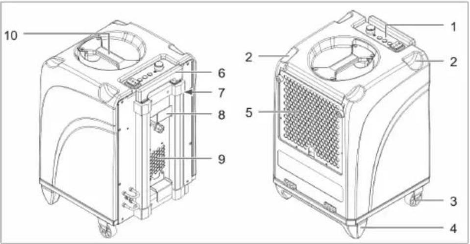
Illustration 1: Front and rear view
| 1 Control panel 2 Recess for stacking | ||
| 3 Castor 4 Base | ||
| 5 Inlet air grille with filter holder 6 Handle | ||
| 7 Operating hours counter 8 Cable winder | ||
| 9 Air outlet 10 Carry handle |
Button/indicator Description
Operating hours counter Display of operating hours
3 Control panel
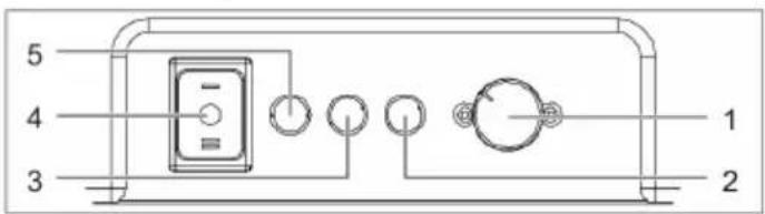
Illustration 2: Control panel
| 1 Hygrostat rotary selector 2 Red fault indicator | |
| 3 Yellow indicator 4 Device switch | |
| 5 Green indicator |
| Button/indicator Description | |
| Device switch Switching device ON/OFF:■ Position [I]: Device continuously on■ Position [II]: Starting pump and draining off condensate | |
| Indicators Operating status of device:■ Green: Device running■ Yellow: Device in defrosting mode■ Red: Fault, device shut down | |
| Hygrostat rotary selector | Setting desired target humidity When the set target humidity is reached, the device is automatically switched off. If the air humidity increases again, the device restarts automatically. |
4 About this operating manual
This operating manual (hereinafter referred to as the manual) allows the operator to operate the humidifier (referred to as the device) safely and efficiently.
Reproduction of this document or parts thereof is only permitted with the explicit written consent of HEYLO GmbH (herein-after referred to as the manufacturer).
NOTICE! Before using the device, please read this manual carefully. Keep this document for future reference.
Safety signs and instructions
DANGER! Warning regarding an imminent risk of injury
This safety instruction warns of an immediate dangerous situation which can lead to serious injury or death.
WARNING! Warning of a potential risk to human life.
This safety instruction warns of a potentially hazardous situation which, if not avoided, could result in death or serious injury.
CAUTION! Warning of a potential risk to human life.
This safety instruction warns of a potentially hazardous situation which, if not avoided, could result in minor to moderate injury.
ATTENTION! Warning regarding damage to property
These safety warnings highlight potential risks of damage to the device.
Contact details of manufacturer
See rear cover.
5 Product description
The device dehumidifies the air in the room. In the process, condensate collects in the condensate tank from where it can be removed by means of a built-in pump to a collecting vessel or an on-site drain. The device is automatically defrosted when necessary.
Scope of delivery
■ Dehumidifier
- Drain hose
■ Filter pad
■ Operating manual
Optional accessory
■ Prod. no. 1306539 Exhaust air adapter for 1 hose (100 mm)
■ Prod. no. 1306553 Exhaust air adapter for 3 hoses (3 x 50 mm)
Type plate
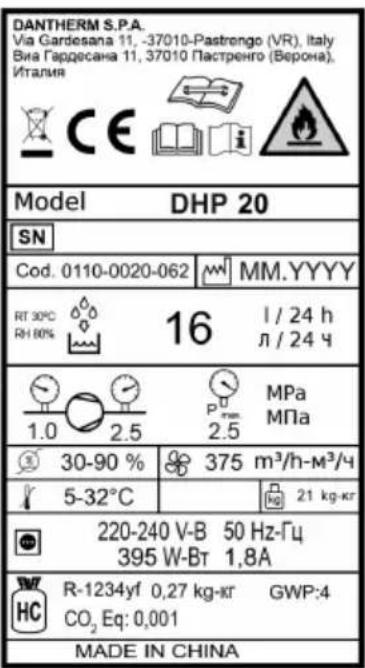
The type plate is attached to the device.
Intended use
The device is intended solely for dehumidifying air at atmospheric pressure in a commercial environment.
Intended use also includes compliance with the operating conditions (see Operating conditions).
Any use other than the specified is deemed improper. Improper use shall void all warranty cover.
The air dehumidifier must not be operated by children or by persons with limited physical, sensory or mental faculties.
Before operating the device, users must have read and understood this operating manual.
Reasonably foreseeable misuse
The device must not be used:
■ In rooms/spaces that are not enclosed, or outdoors
■ In rooms with a potentially explosive or aggressive atmosphere
In rooms with air that has been treated with ozone, or that contains a high concentration or solvents or dust.
■ At locations where the prescribed minimum safety distances cannot be maintained
6 Safety
General safety instructions
■ The device must only be operated by persons who have been properly instructed in its operation.
■ It is forbidden to make any modifications to device.
■ Maintenance and troubleshooting tasks must be performed by suitably qualified persons only. Shut down the device and disconnect the mains plug.
WARNING! Risk of explosion, injury from burns or poisoning by refrigerant
The device is operated with an odourless and flammable refrigerant. If the device is operated incorrectly, there is a risk that the refrigeration causes explosion, fire, poisoning or other injury. The refrigerant is pressurised.
- Only operate the device in rooms larger than 4 m ^2 .
- Never drill holes into the device, and do not use welding equipment or cutting torches in its vicinity.
Do not attempt to speed up defrosting by using implements.
All work on the refrigeration circuit must be performed by staff of the manufacturer or an authorised technician.
Avoid contact with the refrigerant.
When handling the refrigerant, strictly adhere to the applicable safety regulations.
WARNING! Risk of electric shock
When carrying out work on electrically powered components, or if such components come into contact with water, there is a risk of serious or even fatal injury from electric shock.
All work on the electrical equipment must be carried out by qualified electricians.
Take suitable measures to prevent electrically powered components coming into contact with water.
Before moving the device to a different location, disconnect the mains plug and empty the condensate tank.
WARNING! Risk of infection
The condensate may be contaminated with pathogens.
Never drink the condensate.
→ Regularly pump off the condensate. Avoid leaving condensate in the collecting vessel or in the condensate drain hose for a longer period of time.
Operating conditions
The device is intended for mobile or stationary use indoors, on construction sites, as well as in garages and storage rooms. The device operates efficiently:
■ At temperatures between +5 °C and +32 °C and within a relative air humidity range of 40 % to 100 %. Ideal room temperature range: 20 °C to 27 °C.
■ In enclosed rooms where there is as little air exchange as possible.
■ Placed at close as possible to the centre of the room.
■ When the dry air discharged by the device is directed towards the humid part of the room.
Do not use the device under the following ambient conditions:
■ Rooms with a potentially explosive atmosphere, or an atmosphere containing sulphur or salt.
■ Atmospheres with high solvent or dust concentration.
7 Transport and installation
Transport
WARNING! Risk of injury from device toppling over
- Transport the device in an upright position and secure it against tipping or slipping.
Place the device on a level, firm surface.
WARNING! Risk of injury during machine transport
To transport the device, use the handle and the castors.
For heavy loads, work in teams of two and use suitable lifting gear.
Procedure
- Before transporting the device, empty the condensate tank.
- Ensure that the drain hose is removed from the device and that the mains plug is disconnected.
- Transport the device to the location of operation.
- To transport heavy loads, work in teams of two and use suitable lifting gear.
- When the device is at its location of operation, apply the castor brake.
NOTICE! Ensure that the air can circulate freely around and through the device. Do not cover the air inlet and outlet openings. The distance between the air outlet and the air filter must be minimum 1 m.
Unpacking
- Remove the device from the cardboard box and place it on the ground.
- Check the scope of delivery for completeness.
Report any transport damage or incomplete delivery to your dealer.
Adjusting handle
- Release the locking mechanism of the handle, and pull out the handle to the desired length.
Connecting drain hose
For operation, the supplied drain hose must always be connected to the device.
ATTENTION! Poor device performance
Do not kink the drain hose.
Do not place any objects on the hose.
Procedure
- Secure the quick-release coupling of the drain hose to the connector at the rear of the device.
- Lead the drain hose away from the device and place the free end in an on-site drain opening or a sufficiently large collecting vessel (maximum level difference: 6 m).
Stacking devices
For operation or storage, it is permissible to combine maximum two devices in a stack.
- Do to this, loosen and fully retract the handle of the device at the bottom.
- Place the second device on the first one. Ensure that the bases of the second device slot into the recesses in the first one.
Connecting device to electric power mains
- Ensure that the voltage of the power mains corresponds to that specified in Technical data.
-
Ensure that the mains socket is sufficiently protected (see in Technical data).
-
The power socket to which the device is connected must be equipped with a RC circuit breaker. This is particularly important for operation in humid rooms and on construction sites.
- Make sure that the mains socket is earthed and matches the power plug of the device.
- Connect the power plug into the mains socket.
8 Device operation and control
Prior to switching on
- Make sure that the device is not standing on a wet ground and ensure that it is in an upright and stable position.
- Make sure that the condensate can drain off properly.
- If necessary, record the readings of the operating hours counter.
NOTICE! Before starting the device for the first time, after transport and after prolonged storage, leave the device in its final position for approx. 15 minutes before switching it on.
Setting target humidity, switching on device and running it in continuous mode
- Set the hygrostat to the desired target humidity.
- Set the device switch to position [I].
→ The green indicator is lit, indicating that the compressor is running.
The device starts in continuous mode and runs until the set target humidity is reached or the automatic defrost function is triggered (yellow indicator lit). In continuous mode, condensate is automatically pumped off.
The device switches off automatically as soon as the set target humidity is reached. The device remains however in ready mode. If the target humidity is again exceeded, the device is automatically restarted.
Pumping off condensate (before moving device to a different location)
√ The device must not be in defrost mode (yellow indicator must be off).
- Set the device switch to position [II].
⇒ The condensate pump starts to pump the condensate through the drain hose into the drain or the on-site drain / collecting vessel.
- As soon as there is no condensate left in the tank, quickly set the switch to position [0], to prevent the pump from running dry.
Switching device off
- Set the device switch to position [0].
→ The indicator in the device switch is off and the device is shut down.
NOTICE! For planned prolonged stand-stills, pump off the condensate before shutting down the device.
9 Maintenance and care
WARNING! Risk of injury from inhaling harmful substances
Depending on the location of operation, the components of the device may become contaminated with mould or other hazardous organisms or substances.
When using compressed air to clean the device and/or the filter, work in a well-ventilated area, preferably outdoors.
During cleaning, wear safety goggles and a breathing mask.
ATTENTION! Risk of damage to property
Detergents can cause damage to surfaces. Use only mild detergents.
→ Use only approved original spare parts.
Cleaning housing and filter
The cleaning intervals for the device depend on the actual operating conditions. Check and clean the device regularly.
If the device is used for drying at construction sites, it must be checked and cleaned after each use; the air filter must be replaced at least once a week.
- Switch off the device at the device switch.
- Disconnect the power plug.
- Clean the housing with a damp, lint-free cloth and a mild detergent. The original gloss can be restored with polish.
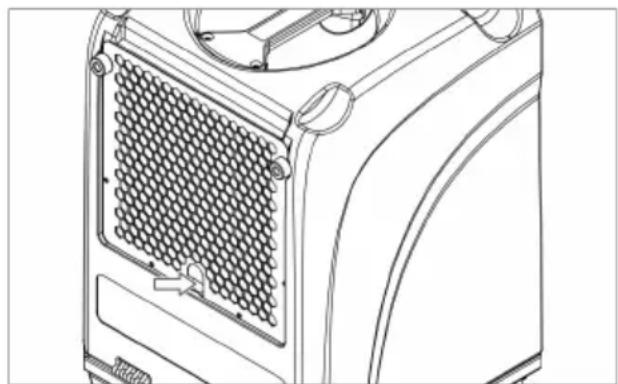
- Remove the filter holder by the recessed grip.
natural_image
Technical line drawing of a mechanical device with a mesh grille and control knobs (no text or symbols)- Take the filter from the housing. For foam filters: Clean the filter thoroughly with a mild detergent and water. Let the filter dry.
- Check the drain fitting and the connected drain hose for damage. Replace damaged components.
-
Insert the new or cleaned filter in the filter holder.
-
Mount the filter holder together with the filter in the same way as it was installed at the factory.
Cleaning evaporator
√ The evaporator must be de-iced and dry.
- Switch off the device at the device switch and disconnect the power plug.
- Remove the housing cover and place it on the ground.
- Clean the cooling coils from both sides with compressed air.
To remove greasy dirt from the cooling coils, proceed as follows:
- Clean the condensate tray under the cooling coils as well as the drain hose.
- Spray the cooling coils with a mild detergent solution, using a spray bottle.
- Let the cleaned components dry.
- Mount the covers in the same way as they were installed at the factory.
→ You have now cleaned the evaporator.
Cleaning pump sump
Depending on the way the device is used, deposits may form in the pump sump. To clean the pump sump, proceed as follows:
- Switch off the device at the device switch and disconnect the power plug.
- Remove the housing cover and place it on the ground.
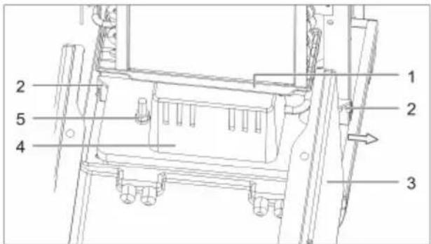
Illustration 3: Removing condensate tank
| 1 Condensate tray | 2 Securing screws of condensate pump |
| 3 Housing 4 Condensate pump | |
| 5 Fixture of condensate pump | |
- Disconnect the condensate hose from the condensate pump.
- Loosen the two securing screws of the condensate pump and slide the pump to the side to remove it from the device. The connecting cable is sufficiently long to remain attached to the device.
- Clean the condensate pump with a damp cloth and a mild detergent.
- Replace the condensate pump in the device. Secure the condensate pump and push the condensate hose into the pump.
Spare parts and customer service
If you have any queries regarding the device, or wish to order spare parts, contact your dealer or HEYLO.
10 Troubleshooting
WARNING! Risk of poisoning by refrigerant, injury from burns, crushing or electric shock during troubleshooting
All work in connection with troubleshooting and repairs must be carried out by authorised personnel or the manufacturer.
In the event of a malfunction, switch off the device and secure it against inadvertent switching on.
Before starting work, allow hot components to cool down.
Faults and malfunctions during operation
In the event of a fault or malfunction, refer to the table below. If necessary, contact the HEYLO Customer Service.
| Fault/malfunction Possible cause Remedy | ||
| No function available in continuous or pump mode (all indicators off) | No or incorrect power supply | Check the power cord and mains connection |
| Device switch is in position ON (continuous mode), but device fails to start (all indicators off) | Overpressure protection tripped due to high ambient temperature | Wait until the device switches on automatically (approx. 5-15 min) |
| Fan running but there is no condensate | Humidity or temperature in room too low | Check the indoor climate values using a thermo-hygrometer |
| Filter clogged Check filter and clean, if necessary | ||
| Refrigeration system defective (in this case, evaporator does not become cold) | Contact the manufacturer | |
| Device is noisy and vibrates, condensate escapes | Device is not in level and upright position | Check the operating conditions, particularly the installation site |
| Device heats up, makes a lot of noise and dehumidifies poorly | Insufficient air circulation; function only available when housing is closed | Ensure that the air can circulate freely; clean evaporator and filter |
| Water escaping from device | Leak in condensate system | Run condensate pump test with water and locate leak |
| Red indicator lit Pump runs dry | Check condensate pump | and drain hose for dirt/blockage |
Table 1: Troubleshooting table
11 Repair
During the warranty period, all repairs must be performed by persons authorised by the manufacturer.
After the warranty period has elapsed, certain repair can be carried out by the device owner, provided he or she has the necessary skills. Such repairs are not covered by the manufacturer's warranty.
If you have any queries concerning the repair of your device, contact your dealer or HEYLO Customer Service.
12 Decommissioning, storage and disposal
Decommissioning
- Pump out the condensate.
- Switch off the device at the device switch and disconnect the power plug.
- Clean the device (see Maintenance and cleaning).
- Disconnect all incoming and outgoing lines (discharge and power supply lines).
- Package the device so that it is protected against moisture and dust.
Storage
CAUTION! Risk of injury from device top-pling over
Do not stack more than two devices one on top of the other.
→ Secure devices against toppling over.
Procedure
Store the device at a temperature between 5 °C and +40 °C.
Disposal
CAUTION! Risk of damage to the environment from hazardous substances
Dismantle the device and recycle or dispose of the materials according to the applicable statutory regulations.
For the disposal of auxiliary materials and consumables, observe the information in the safety data sheets and the applicable statutory regulations.

Do not dispose of the device as household waste.
13 EC Declaration of Conformity
| EC Declaration of Conformity in accordance with Low Voltage Directive 2014/35/EC Annex IV | |||
| Manufacturer: DANTHERM S.p.A | Via Gardesana 11 370 | 10- Pastrengo (VR), ITALY | |
| Product: Dehumidifier Type: DHP 20 | |||
| We herewith declare that the machine conforms to all relevant requirements of the following EU Directives:■ 2014/35/EU Low Voltage Directive■ 2014/30/EU EMC Directive■ 2011/65/EU RoHS Directive | |||
| The following harmonised standards have been applied: | |||
| EN 60335-1 EN 60335-2-40 EN 55014-1:2017 EN 55014-2:2015 | |||
| Pastrengo, 2022 | Stefano Verani — Member of the Board | ||
II. IT - ISTRUZIONI PER L'USO
natural_image
Line drawing of a mechanical device with a mesh grille and control knob (no text or symbols)natural_image
Technical line drawing of a mechanical device with a grid-patterned panel and mounting bracket (no text or symbols)natural_image
Technical line drawing of a mechanical device with a grid-patterned panel and mounting bracket (no text or symbols)natural_image
Technical line drawing of a mechanical device with a grid-patterned panel and mounting bracket (no text or symbols)- Retirez le filtre encrassé.
natural_image
Technical line drawing of a mechanical device with a grid-patterned panel and mounting bracket (no text or symbols)natural_image
Technical line drawing of a mechanical device with a grid-patterned panel and mounting bracket (no text or symbols)natural_image
Technical line drawing of a mechanical device with a grid-patterned panel and adjustment knobs (no text or symbols)- Remova o filtro sujo.
natural_image
Technical line drawing of a mechanical device with a grid-patterned panel and mounting bracket (no text or symbols)natural_image
Technical line drawing of a mechanical device with a grid-patterned panel and mounting bracket (no text or symbols)ADVARSEL! Fare for personskade under transport
natural_image
Technical line drawing of a mechanical device with a grid-patterned panel and mounting bracket (no text or symbols)natural_image
Technical line drawing of a mechanical device with a grid-patterned panel and mounting bracket (no text or symbols)Unit 2B, 512 Yunchuan Rd.,
Shanghai, 201906, CHINA
Dantherm SP S.A.
C/Calabozos, 6 Polígono Industrial, 28108
Alcobendas, Madrid, SPAIN
Dantherm S.p.A.
Виа Гардесана 11,37010