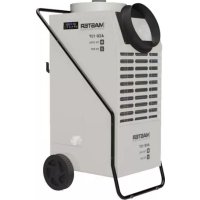
ACD 137 - Dehumidifier Master - Free user manual and instructions
Find the device manual for free ACD 137 Master in PDF.



| Product type | Dehumidifier with cooling and ventilation functions |
| Brand | Master |
| Model | ACD 137 |
| Refrigerant gas | R1234yf (flammable, GWP = 4) |
| Supply voltage | 230 V ~ 50 Hz (check rating plate) |
| Operating modes | Cooling (COOL), Dehumidification (DRYER), Ventilation (FAN) |
| Fan speed | Low (LOW) and High (HIGH) |
| Control panel | Digital display and LED indicators |
| Display | Shows [ - - ] in standby, set point, operating hours |
| Continuous drain connection | Possible via 3/4" male hose (remove the tank) |
| Air filter | Removable, located at the rear |
| Filter cleaning frequency | At least once a month |
| Full tank alarm | Signaled by "FULL" on display, resets after emptying |
| Low ambient temperature alarm | "Lo t" on display |
| Humidity sensor alarm | "Prob" on display (operation maintained) |
| Temperature sensor alarm | "Pro2" on display |
| Defrost thermostat alarm | "dEFr" on display |
| High pressure alarm | "HiPS" (clean filters, reset pressure switch) |
| Low pressure alarm | "LoPS" (clean filters, unplug/replug) |
| Protection | Mandatory grounding, unplug before maintenance |
| Optional accessory | Remote thermostat (compatible with COOL mode) |
| Use | Indoor only |
| Safety instructions | Do not insert objects into the grilles, do not use water for cleaning |
Frequently Asked Questions - ACD 137 Master
User questions about ACD 137 Master
0 question about this device. Answer the ones you know or ask your own.
Ask a new question about this device
Download the instructions for your Dehumidifier in PDF format for free! Find your manual ACD 137 - Master and take your electronic device back in hand. On this page are published all the documents necessary for the use of your device. ACD 137 by Master.
USER MANUAL ACD 137 Master
natural_image
Technical line drawing of a portable air purifier with labeled components and exploded view (no text or symbols)PICTURES - FIGURE - ABBILDUNGEN - FIGURAS - FIGURES - FIGUREN - FIGU- RAS - FIGURER - KUVAT - FIGURER - FIGURER - ILUSTRACJE - ИЛЛЮСТРАЦИИ - OBRÁZKY - ÁBRÁK - SLIKE - ŞEKİLLER - SLIKE - ILIUSTRACIJOS - ATTĚLI - JOONISED - IMAGINI - OBRÁZKY - CXEMI - МАЛЮНКИ - SLIKE - EIKONEΣ - 图示 - СУРЕТТЕМЕЛЕР
4
5
PICTURES - FIGURE - ABBILDUNGEN - FIGURAS - FIGURES - FIGUREN - FIGU- RAS - FIGURER - KUVAT - FIGURER - FIGURER - ILUSTRACJE - ИЛЛЮСТРАЦИИ - OBRÁZKY - ÁBRÁK - SLIKE - ŞEKİLLER - SLIKE - ILIUSTRACIJOS - ATTĚLI - JOONISED - IMAGINI - OBRÁZKY - CXEMI - МАЛЮНКИ - SLIKE - EIKONEΣ - 图示 - СУРЕТТЕМЕЛЕР
6
PICTURES - FIGURE - ABBILDUNGEN - FIGURAS - FIGURES - FIGUREN - FIGU- RAS - FIGURER - KUVAT - FIGURER - FIGURER - ILUSTRACJE - ИЛЛЮСТРАЦИИ - OBRÁZKY - ÁBRÁK - SLIKE - ŞEKİLLER - SLIKE - ILIUSTRACIJOS - ATTĚLI - JOONISED - IMAGINI - OBRÁZKY - CXEMI - МАЛЮНКИ - SLIKE - EIKONEΣ - 图示 - СУРЕТТЕМЕЛЕР
PICTURES - FIGURE - ABBILDUNGEN - FIGURAS - FIGURES - FIGUREN - FIGU- RAS - FIGURER - KUVAT - FIGURER - FIGURER - ILUSTRACJE - ИЛЛЮСТРАЦИИ - OBRÁZKY - ÁBRÁK - SLIKE - ŞEKİLLER - SLIKE - ILIUSTRACIJOS - ATTĚLI - JOONISED - IMAGINI - OBRÁZKY - CXEMI - МАЛЮНКИ - SLIKE - EIKONEΣ - 图示 - СУРЕТТЕМЕЛЕР
NOTE:
1... INTRODUCTION
2... GENERAL DESCRIPTION OF THE UNIT
3... PRELIMINARY OPERATIONS
4... START-UP
5... MAINTENANCE
6... ALARM LIST
▶▶▶1. INTRODUCTION
▶▶1.1. INTRODUCTION
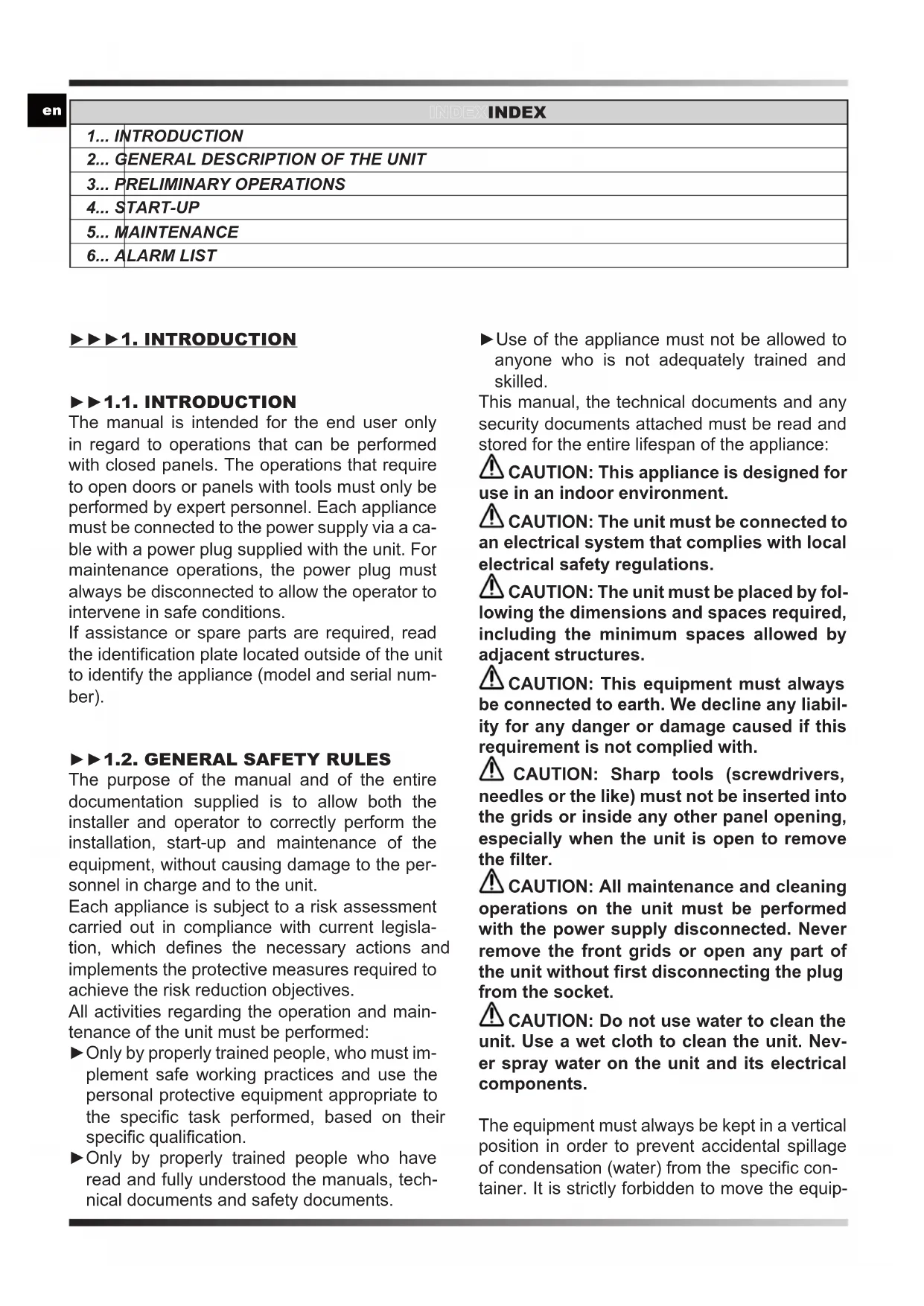
The manual is intended for the end user only in regard to operations that can be performed with closed panels. The operations that require to open doors or panels with tools must only be performed by expert personnel. Each appliance must be connected to the power supply via a cable with a power plug supplied with the unit. For maintenance operations, the power plug must always be disconnected to allow the operator to intervene in safe conditions.
If assistance or spare parts are required, read the identification plate located outside of the unit to identify the appliance (model and serial number).
▶▶1.2. GENERAL SAFETY RULES
The purpose of the manual and of the entire documentation supplied is to allow both the installer and operator to correctly perform the installation, start-up and maintenance of the equipment, without causing damage to the personnel in charge and to the unit.
Each appliance is subject to a risk assessment carried out in compliance with current legislation, which defines the necessary actions and implements the protective measures required to achieve the risk reduction objectives.
All activities regarding the operation and maintenance of the unit must be performed:
▶ Only by properly trained people, who must implement safe working practices and use the personal protective equipment appropriate to the specific task performed, based on their specific qualification.
▶ Only by properly trained people who have read and fully understood the manuals, technical documents and safety documents.
▶Use of the appliance must not be allowed to anyone who is not adequately trained and skilled.
This manual, the technical documents and any security documents attached must be read and stored for the entire lifespan of the appliance:
⚠️ CAUTION: This appliance is designed for use in an indoor environment.
⚠️ CAUTION: The unit must be connected to an electrical system that complies with local electrical safety regulations.
⚠️ CAUTION: The unit must be placed by following the dimensions and spaces required, including the minimum spaces allowed by adjacent structures.
⚠️ CAUTION: This equipment must always be connected to earth. We decline any liability for any danger or damage caused if this requirement is not complied with.
CAUTION: Sharp tools (screwdrivers, needles or the like) must not be inserted into the grids or inside any other panel opening, especially when the unit is open to remove the filter.
⚠️ CAUTION: All maintenance and cleaning operations on the unit must be performed with the power supply disconnected. Never remove the front grids or open any part of the unit without first disconnecting the plug from the socket.
⚠️ CAUTION: Do not use water to clean the unit. Use a wet cloth to clean the unit. Never spray water on the unit and its electrical components.
The equipment must always be kept in a vertical position in order to prevent accidental spillage of condensation (water) from the specific container. It is strictly forbidden to move the equip-
ment while connected to the power outlet, as the resulting vibrations and movements may cause the condensation to leak from the specific container, thus affecting the electrical parts.
The unit can only be moved after emptying the condensate tank, and in any case, it is ALWAYS REQUIRED to remove the plug from the socket before moving the appliance. Should water be accidentally spilled on the appliance, the unit must be immediately turned off and disconnected from the power supply and may only be turned on after eight HOURS/TAC have elapsed.

CAUTION: The equipment contains R1234yf refrigerant: this gas is flammable. The amount of charge is indicated in the data table of this user manual.
Warning, the refrigerant is odourless.
Do not use any means to accelerate the defrosting process or for cleaning other than those recommended by the manufacturer.
The appliance must be placed in a room that does not have ignition sources continuously in operation (e.g. open flames, a gas appliance while running or an electric heater running).
Do not drill holes into or burn the appliance.
▶▶1.3. PERSONAL PROTECTIVE EQUIPMENT
Use the following personal protective equipment during unit use and maintenance operations:
⚠ CLOTHING: Those who carry out maintenance or work on the unit in environments with slippery floors must wear safety shoes with non-slip soles.
⚠️ GLOVES: Appropriate gloves must be worn during cleaning and maintenance operations. When refilling the refrigerant gas, the use of appropriate gloves is mandatory in order to prevent the risk of freezing.
⚠️ MASK AND GOGGLES: Masks to protect the respiratory tract and safety goggles to protect the eyes must be worn during cleaning and maintenance operations.
▶▶1.4. GENERAL SAFETY RULES
The following safety signs, which must be respected, are affixed on the unit:
Read the user manual.
Read the technical manual.
Electric shock hazard.
Flammable material hazard.
⚠️ CAUTION: It is strictly forbidden to remove the safety signs on the units.
▶▶▶2. GENERAL DESCRIPTION OF THE UNIT
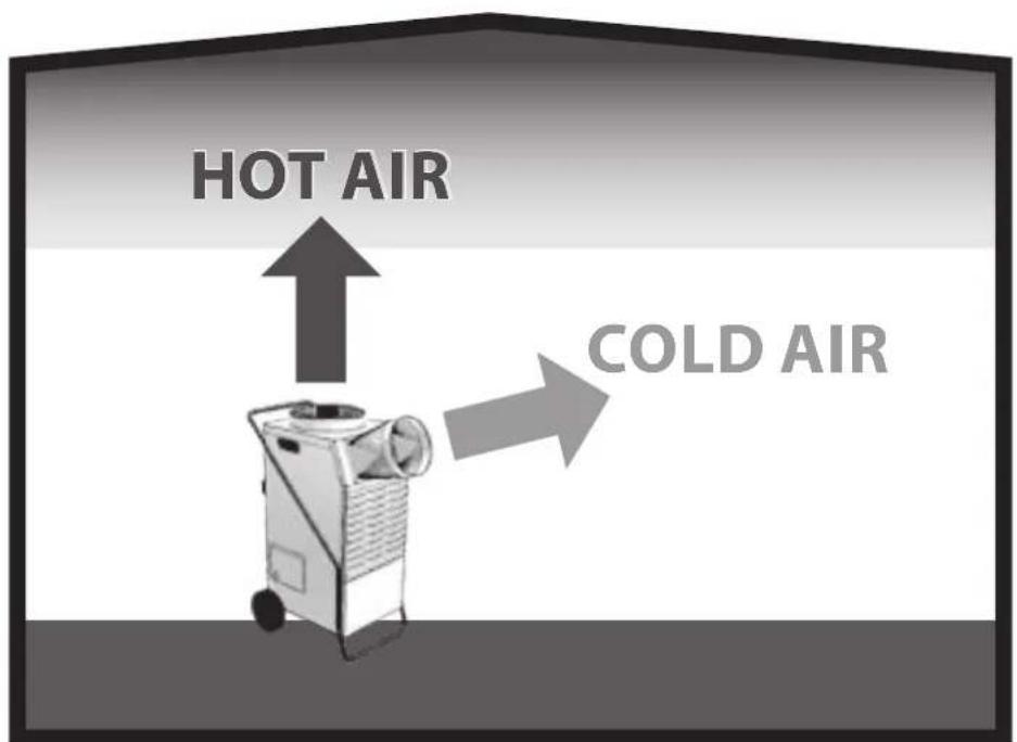
(PIC. 1)
(PIC. 2)
A. Ambient air inlet.
B. Ambient air inlet.
C. Hot air outlet.
D. Cold air outlet.
This appliance allows you to control the ambient temperature and relative humidity. The available functions are cooling, dehumidification and ventilation.
For correct ambient climate control, it is necessary to adapt the appliance and select the correct desired operating mode via the control panel, considering that the lower grids (front and rear) draw in the ambient air, whereas the upper grids release air into the environment [the upper/front grid (D PIC. 2) releases cold air, whereas the upper grid (C PIC. 2) releases hot air].
Refer to the "CONTROL PANEL" paragraph for the operating modes.
▶▶2.1. REFRIGERANT CIRCUIT
The refrigerant gas used in these units is R1234yf. The refrigerant circuit is built in compliance with current standards.

Flammable material hazard.
This unit is hermetically sealed and contains fluorinated gas R1234yf GWP (R1234yf) = 4.
▶▶▶3. PRELIMINARY OPERATIONS
▶▶3.1. REMOVAL OF THE PACKAGING AND ASSEMBLY
(PIC. 3)
Remove the packaging taking care not to damage the unit. Dispose of the packaging products (wood, plastic, cardboard), taking them to the specialised collection or recycling centres (follow the local regulations in force).
CAUTION: Assemble the appliance, with the adequate air outlet (1 or 2-way outlet, depending on the model), handles, wheels, cord reel and all the relevant nuts and bolts, before operating it.
NOTE: Correct operation requires the appropriate air outlet to be installed, according to the actual requirements (depending on the model).
▶▶3.2. INSPECTION
All units are factory assembled and wired (except for certain components). Upon receiving the unit, it must be immediately and thoroughly inspected, checking that it has not been damaged during transport or that no parts are missing.
Before use, specifically check for any dents on the external metal panels, including those in the tank compartment. Also check that the cable, plug and relevant insulation are intact. Otherwise, it is FORBIDDEN to connect and start the unit, which must be sent to an authorised service centre.
▶3.3. OPERATING PRINCIPLES
⚠️ CAUTION: To ensure correct operation of the appliance, it is recommended to operate the unit within the limits shown on the technical data table.
▶▶3.4. POSITIONING
Set up the appliance to ensure an adequate air flow.
⚠️ CAUTION: Make sure that the appliance is placed in such a way so as to prevent contact with water.
▶▶3.5. SERVICE AREA
The hot air expelled by the fan must not be obstructed. Avoid recirculation phenomena of the air expelled and drawn by the appliance so as to prevent compromising the performance of the unit or even interrupting normal operation.
⚠️ CAUTION: The equipment must not be placed in cramped environments, which do not allow adequate distribution of the air from the dedicated inlets and outlets in the room.
⚠️ CAUTION: Do not place or hang objects on the front panel, it may cause damage to the unit.
▶3.6. GENERAL INFORMATION
⚠️ CAUTION: Disconnect the power plug from the socket before carrying out any maintenance operation on the electrical part.
CAUTION: Check that the supply voltage corresponds to the unit's operating data (voltage and frequency) shown on the data plate on the dehumidifier. The appliance is fitted with a power cable for correct operation.
CAUTION: The earthing connection is mandatory.
▶▶▶4. START-UP
▶▶4.1. PRELIMINARY CHECKS
CAUTION: Check that the power cord is y connected.
CAUTION: Check that all the cover pan-in the correct position and are locked via crews before commissioning.
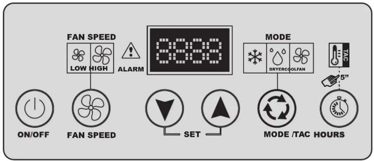
▶▶4.2. CONTROL PANEL
(PIC. 4)
The unit is equipped with a luminous control panel, which indicates the operating status of the appliance.
A brief description is provided below:
CONTROL PANEL:
▶[--] (SHOWN ON THE DISPLAY): The display shows [--] when the unit is connected to the mains and electrically powered.
LED:
▶FAN SPEED LED: These LEDs indicate the set ventilation speed (LOW > Low speed / HIGH > High speed).
▶ ALARM LED: This LED is on when the unit is in alarm. The display will show the error message.
▶ MODE LED: These LEDs indicate the selected operating mode:
-COOL LED: This LED indicates that the appliance is operating in "COOLING" mode.
This LED flashes during defrosting or if the temperature set point is reached.
-LED DRYER: This LED indicates that the appliance is operating in “DEHUMIDIFICATION” mode.
This LED flashes during defrosting or if the humidity set point is reached.
-LED FAN: This LED indicates that the appliance is operating in "VENTILATION" mode.
BUTTONS:
▶ ON/OFF: Press "ON/OFF" to turn the appliance on.
Press the "ON/OFF" button to turn the appliance off (with the appliance off, the display shows [ - - ]).
NOTE: When the appliance is turned off and then on immediately, the compressor does not start immediately. After a few minutes, the appliance restarts automatically.
▶FAN SPEED: Press the “FAN SPEED” button to select the desired ventilation speed (LOW > Low Speed / HIGH > High Speed).
▶ SET “▼” / “▲” (SET POINT): By pressing the SET “▼” / “▲” buttons it is possible to set the desired set point value. The display will start flashing, showing the new reference set point.
After a few seconds the display stops flashing and the new set point has been detected by the electronics.
It is possible to operate the appliance regardless of the degree of temperature or humidity in the environment; in fact, the appliance will work continuously while pressing the “▼” button until “CONT” appears on the display.
▶MODE: Press the "MODE" button to select the desired operating mode:
- COOLING MODE (PIC. 5) [COOL MODE]: Select the "COOL" cooling mode on the control panel.
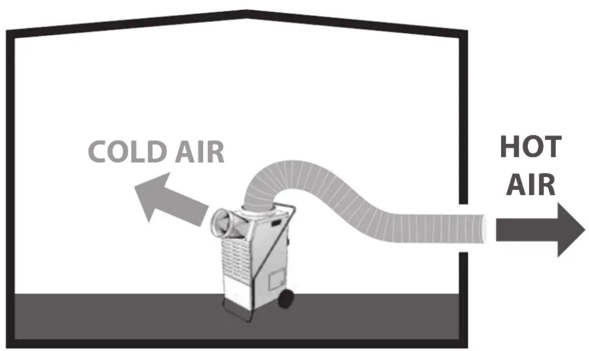
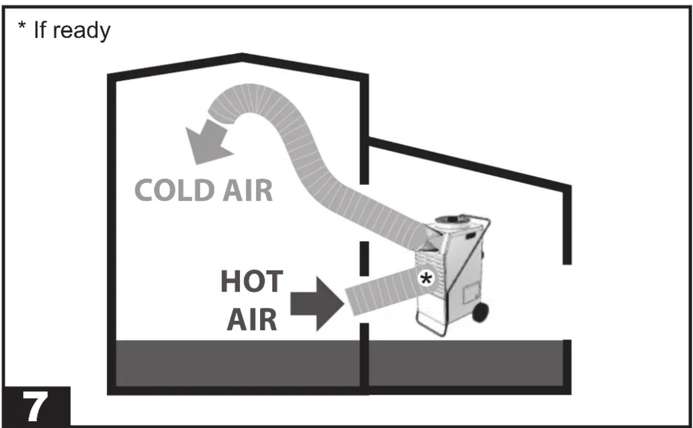
- COOLING MODE WITH DUCTING (PIC. 6-7) [COOL MODE]:
- I° - Duct the hot air from the upper grid (C PIC. 2) to outside the room.
- II° - Select the “COOL” cooling mode on the control panel.
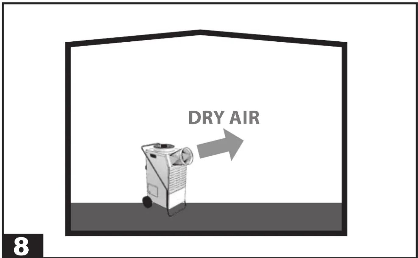
- DEHUMIDIFICATION MODE (PIC. 8) [DRYER MODE]: Select the "DRYER" dehumidification mode on the control panel.
▶ HOURS/TAC: Press the "HOURS/TAC" button to view the working HOURS/TAC of the appliance.
▶▶4.3. DISCHARGE PIPE CONNECTION (Set-up)
A discharge pipe can be connected to the appliance. Remove the tank and connect a fixed pipe to the condensate drain ( ^3/_4 " male fitting).
▶▶4.4. CONNECTING AIR DUCTING PIPES
Air ducting pipes can be connected to the appliance. It is recommended to use only pipes of adequate section and to avoid bends or narrowing of the duct sections.
It is forbidden to move the appliance when it is ON and when it is connected to ducting pipes.
▶▶4.5. CONNECTION AND ACTIVATION OF THE REMOTE TEMPERATURE CONTROL (optional)
(Valid for cooling only)
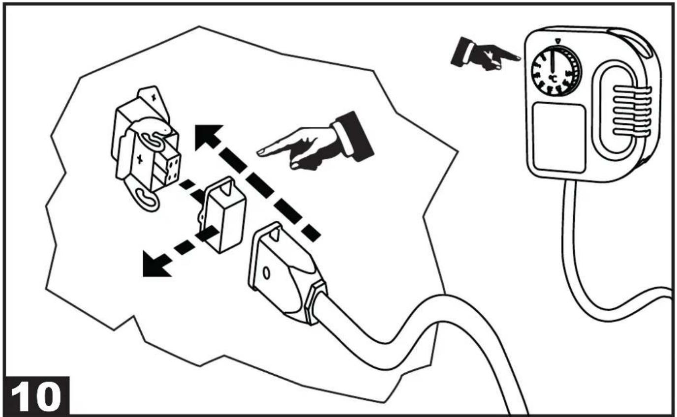
(PIC. 10)
NOTE: Use only original accessories.
Depending on the model, it is possible to connect a remote temperature control to the appliance in order to obtain the desired temperature in the room, even remotely (only compatible with the cooling feature).
With the appliance in stand-by mode (i.e. product switched off but powered by electricity), connect the remote temperature control (PIC. 10), press the "HOURS/TAC" button for about 5" on the control panel and set the desired temperature on the remote temperature control. The control panel display will show "RC". The "COOL" LED will flash during defrosting or if the temperature set point is reached.
▶▶▶5. MAINTENANCE
▶▶5.1. CHECKS TO BE PERFORMED BY THE USER
The only maintenance to be carried out by the user is the cleaning of the air filter, which must be performed at least once a month.
The cleaning frequency can be increased due to the dustiness of the working environment of the appliance.
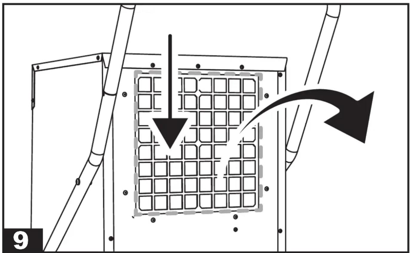
The filter is on the rear of the appliance. Remove the filter gently (PIC. 9) and then remove the dust by means of a low pressure air flow.
CAUTION: REMOVE THE FILTER FROM THE APPLIANCE TO PERFORM CLEANING. IT IS FORBIDDEN TO PERFORM CLEANING WITH THE FILTER INSTALLED.
▶5.2. SPARE PARTS
Should it be required to replace one or more parts during maintenance by specialised operators, this must be done by using original spare parts only.
If required, request the “spare parts list” from your vendor, specifying the model and serial number of the unit.
▶5.3. DISMANTLING THE UNIT
The unit has been designed and built to ensure continuous operation. The lifespan of some components such as the fan and the compressor depends on their maintenance.
CAUTION: The unit contains substances and components dangerous for the environment (electronic components, refrigerant gas and oils). At the end of its useful life, in the event of dismantling the unit, the operation must be carried out by specialised refrigerating personnel.
The unit must be sent to specific specialised centres for the collection and disposal of equipment containing dangerous substances. The refrigerant fluid and the lubricating oil contained in the circuit must be recovered, in accordance with the regulations in force in your country.
▶▶▶6. ALARM LIST
| ALARM POSSIBLE CAUSE | POSSIBLE SOLUTION | |
| FULL + “FULL” Full or missing | ng tank The alarm is autom | atically reset by empty-ing or inserting the tank |
| ALARM + “Lo t” Room temperature | low | Room temperature conditions not suitable for operation |
| ALARM + “Prob” Malfunction | of the humidity probe. In any case, the unit continues to operate | Contact the authorised service centre |
| ALARM + “Pro2” Malfunction | of the ambient temperature probe | Contact the authorised service centre |
| ALARM + “dEFr” ALARM + “Lotd” | Defrosting thermostat malfunction | Contact the authorised service centre |
| ALARM + “HiPS” High pressure | sure alarm in the refrigerant circuit | Clean both the air filters.Disconnect the unit from the power supply.Open the electrical panel and reset the high pressure switch.If the alarm persist contact the authorised service centre |
| ALARM + “LoPS” Low pressure | sure alarm in the refrigerant circuit | Clean both the air filters.Disconnect the unit from the power supply and riconnect.If the alarm persist contact the authorised service centre |
INDICE INDICE
▶▶▶3. OPÉRATIONS PRÉLIMINAIRES
▶▶3.1. DÉBALLAGE ET ASSEMBLAGE (FIG. 3)
▶▶4.3. BRANCHEMENT D'UN TUYAU D'ÉVACUATION (agencement)
▶▶1.2. GENERELLE SIKKERHEDSREG-LER
IMPORTANT: In order to have a correct function you must use an electrical generator in class G3 or more (frequency variation ±1%, tension variation ±2%). The maximum power of electrical generator must be three time the nominal power of device that you must connect.
| CE CONFORMITY CERTIFICATE | CE |
| CE CONFORMITY CERTIFICATE - DICHIARAZIONE DI CONFORMITÀ CE - EG-KONFORMITÄT-SERKLÄRUNG - DECLARACIÓN DE CONFORMIDAD CE - DECLARATION DE CONFORMITE CE - EG-CONFORMITEITVERKLARING - DECLARAÇÃO DE CONFORMIDADE CE - EU-OVERENSSTEMMELSESERKLÆRING - EY-VAATIMUSTENMUKAISUUSVAKUUTUS - CE-SAMSVAR-SERKLÆRING - EG-FÖRSÄKRAN OM ÖVERENSSTÄMMELSE - DEKLARACJA ZGODNOŚCI WE - ДЕКЛАРАЦИЯ О COOTBETCTВИИ CE - PROHLÁŠENÍ O SHODĚ CE - EK MEGFELELŐSÉGI NYILATKOZAT - IZJAVA O SKLADNOSTI IN OZNAKA CE - CE UYGUNLUK BEYANI - IZJAVA CE O SUKLADNOSTI - ES ATITIKTIES DEKLARACIJA - EK ATBILSTĪBAS - DEKLARĀCIJA - EŪ VA-STAVUSDEKLARATSIOON - DECLARAȚIE DE CONFORMITATE CE - PREHLÁŠENIE O ZHODE CE - ДЕКЛАРАЦИЯ ЗА СЪВМЕСТИМОСТ CE - ДЕКЛАРАЦІЯ ВІДПОВІДНОСТІ CE - IZJAVA CE O PRIKLADNOSTI ΔΗΛΩΣΗ ΣΥΜΜΟΡΦΩΣΗΣ CE - CE 符合性声明DANTHERM S.p.A. Via Gardesana 11, -37010- Pastrengo (VR), ITALYProduct: - Prodotto: - Produkt: - Produkt: - Produkt: - Produkt: - Produkt: - Produkt: - Produkt: - Produkt: - Изделие: - Výrobek: - Termék: - Izdelek: - Ürün: - Proizvod: - Gaminys: - Ierīce: - Toode: - Produsul: - Výro-bok: - Продукт: - Виріб: - Proizvod: - Проїїв: - 产品: | |
| ACD 137 - AC 22 | |
We declare that it is compliant with: - Si dichiara che è conforme a: - Es wird als konform mit den folgenden Normen erklärt: - Se declara que está en conformidad con: - Nous déclarons sa conformité à: - Hierbij wordt verklaard dat het product conform is met: - Declara-se que está em conformidade com: - Vi erklærer at produktet er i overensstemmel-se med: - Vakuutetaan olevan yhdenmukainen: - Man erklærer at apparatet er i overensstemmelse med: - Härmed intygas det att produkten är förenlig med följande: - Oświadcza się, że jest zgodny z: - Заявляем о соответствии требованиям: - Prohlašuje se, že je v souladu s: - Kijelentjük, hogy a termék megfelel az alábbiaknak: - Izpolnjuje zahteve: - Aşağıdaki standartlara uygun olduğunu beyan ederiz: - Izjavljuje se da je u skladu s: - Pareiškiame, kad atitinka: - Tiek deklarēts, ka atbilst: - Käesolevaga deklareeritakse, et toode vastab: - Declarăm că este conform următoarelor: - Prehlasuje sa, že je v súlade s: - Декларира се че отговаря на: - Відповідає вимогам: - Izjavljuje se da je u skladu s: - Δηλώνουμε ότι είναι σύμφωνο με: - 兹证明符合:2014/30/EU, 2014/35/EU, 2011/65/EUEN 60335-1; EN 60335-1 (2012)-AC; EN 60335-1 (2012)-A11;EN 60335-1 (2012)-A13; EN 60335-1 (2012)-A1; EN 60335-1 (2012)-A2;EN 60335-1 (2012)-A14; EN 60335-1 (2012)-A15; EN 60335-2-40;EN 60335-2-40 (2003)-A11; EN 60335-2-40 (2003)-A12; EN 55014-1;EN 55014-1 (2017)-A11; EN 55014-2; EN 55014-2 (1997)-AC; EN 55014-2 (1997)-A1;EN 55014-2 (1997)-A2; EN IEC 63000;IEC 60335-2-40; EN 378-2; Pastrengo, 2023Stefano Verani (Member of the Board) Pastrengo, 2023Stefano Verani (Member of the Board) | |
| UKCA CONFORMITY CERTIFICATE | UKCA |
| UKCA CONFORMITY CERTIFICATE | |
| DANTHERM S.p.A. Via Gardesana 11, -37010- Pastrengo (VR), ITALYProduct: | |
| ACD 137 - AC 22 | |
| We declare that it is compliant with:2014/30/EU, 2014/35/EU, 2011/65/EUBS EN 60335-1; BS EN 60335-1 (2012)-AC; BS EN 60335-1 (2012)-A11;BS EN 60335-1 (2012)-A13; BS EN 60335-1 (2012)-A1; BS EN 60335-1 (2012)-A2;BS EN 60335-1 (2012)-A14; BS EN 60335-2-40;BS EN 60335-2-40 (2003)-A11; BS EN 60335-2-40 (2003)-A12; BS EN 55014-1;BS EN 55014-1 (2017)-A11; BS EN 55014-2; BS EN 55014-2 (1997)-AC; BS EN 55014-2 (1997)-A1; BS EN 55014-2 (1997)-A2; BS EN IEC 63000; BS EN 378-2; | |
| Pastrengo, 2023Stefano Verani (Member of the Board) | |
NOTE:
▶en - DISPOSAL OF THE PRODUCT
-This product has been designed and manufactured with top-quality materials and components, which can be re-cycled and re-used. -When a crossed-wheely bin symbol is attached to the product, it means that the product is protected by the, 2012/19/UE European Directive.
-Please obtain information regarding the local differentiated collection system for electrical and electronic products.
-Respect local Standards in force and do not dispose of old products as normal domestic waste. Correct disposal of the product helps to prevent possible negative consequences for health, the environment and mankind.
▶pl - UTYLIZACJA PRODUKTU
▶Iv - PRODUKTA IZNĪCINĀŠANA

- NOTE:
- ▶▶▶1. INTRODUCTION
- ▶▶1.1. INTRODUCTION
- ▶▶1.2. GENERAL SAFETY RULES
- ▶▶1.3. PERSONAL PROTECTIVE EQUIPMENT
- ▶▶1.4. GENERAL SAFETY RULES
- ▶▶▶2. GENERAL DESCRIPTION OF THE UNIT
- ▶▶2.1. REFRIGERANT CIRCUIT
- Flammable material hazard.
- ▶▶▶3. PRELIMINARY OPERATIONS
- ▶▶3.1. REMOVAL OF THE PACKAGING AND ASSEMBLY
- ▶▶3.2. INSPECTION
- ▶3.3. OPERATING PRINCIPLES
- ▶▶3.4. POSITIONING
- ▶▶3.5. SERVICE AREA
- ▶3.6. GENERAL INFORMATION
- ▶▶▶4. START-UP
- ▶▶4.1. PRELIMINARY CHECKS
- ▶▶4.2. CONTROL PANEL
- CONTROL PANEL:
- LED:
- BUTTONS:
- ▶▶4.3. DISCHARGE PIPE CONNECTION (Set-up)
- ▶▶4.4. CONNECTING AIR DUCTING PIPES
- ▶▶4.5. CONNECTION AND ACTIVATION OF THE REMOTE TEMPERATURE CONTROL (optional)
- (Valid for cooling only)
- ▶▶▶5. MAINTENANCE
- ▶▶5.1. CHECKS TO BE PERFORMED BY THE USER
- ▶5.2. SPARE PARTS
- ▶5.3. DISMANTLING THE UNIT
- INDICE INDICE
- ▶▶▶3. OPÉRATIONS PRÉLIMINAIRES
- ▶▶3.1. DÉBALLAGE ET ASSEMBLAGE (FIG. 3)
- ▶▶4.3. BRANCHEMENT D'UN TUYAU D'ÉVACUATION (agencement)
- ▶▶1.2. GENERELLE SIKKERHEDSREG-LER
- ▶en - DISPOSAL OF THE PRODUCT
- ▶pl - UTYLIZACJA PRODUKTU
- ▶Iv - PRODUKTA IZNĪCINĀŠANA
Brand : Master
Model : ACD 137
Category : Dehumidifier