TIG 220 DC HF FV - Welding machine GYS - Free user manual and instructions
Find the device manual for free TIG 220 DC HF FV GYS in PDF.
| Product type | TIG DC HF welding machine with MMA process |
| Brand | GYS |
| Model | TIG 220 DC HF FV |
| Power supply voltage | 110-240 V single-phase (Flexible Voltage) |
| Frequency | 50/60 Hz |
| Nominal output current (TIG) | 5 to 220 A |
| Nominal output current (MMA) | 10 to 200 A |
| Open circuit voltage | 76 V |
| Peak ignition voltage | 9 kV |
| Duty cycle at 40°C (TIG at 220 A) | 30% |
| Duty cycle at 40°C (MMA at 200 A) | 25% |
| Dimensions (L x W x H) | 42 x 23 x 35 cm |
| Weight | 12 kg |
| Protection degree | IP21 |
| Welding processes | TIG DC, pulsed TIG DC, spot TIG, MMA |
| Ignition types | HF (high frequency) non-contact, Lift (contact) |
| Torch modes | 2T, 4T, 4T LOG |
| Welding functions | Pre-gas, post-gas, ramp up/down, hot start, arc force, pulsed mode |
| Program memories | 10 in TIG, 10 in MMA |
| Remote control | Manual (ref. 045675) or foot pedal (ref. 045682) |
| Compatible cooler | WCU0.5kW_A or WCU1kW_A (optional) |
| Torch connector | SRL18 connector for 1 or 2 trigger torch + potentiometer |
| Recommended maintenance | Regular dusting, checking connections, inspecting power cable |
| Safety | Thermal protection, over/under voltage protection, emergency stop by switch |
| Warranty | 2 years parts and labor |
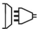
| Included accessories | CEE17 3-pole 16A plug, power cable |
Frequently Asked Questions - TIG 220 DC HF FV GYS
User questions about TIG 220 DC HF FV GYS
0 question about this device. Answer the ones you know or ask your own.
Ask a new question about this device
Download the instructions for your Welding machine in PDF format for free! Find your manual TIG 220 DC HF FV - GYS and take your electronic device back in hand. On this page are published all the documents necessary for the use of your device. TIG 220 DC HF FV by GYS.
USER MANUAL TIG 220 DC HF FV GYS
natural_image
Line drawings of two industrial testing devices with control panels and buttons (no text or symbols)FR 2 / 3-14 / 86-92
EN 2 / 15-25 / 82-92
DE 2 / 26-37 / 82-92
ES 2 / 38-49 / 82-92
RU 2 / 50-61 / 82-92
NL 2 / 62-73 / 82-92
IT 2 / 74-85 / 82-92
TIG 220 DC
TIG 300 DC
FIG-1
TIG 220 DCTIG 300 DC
text_image
Technical diagram of an electronic device with numbered components for identification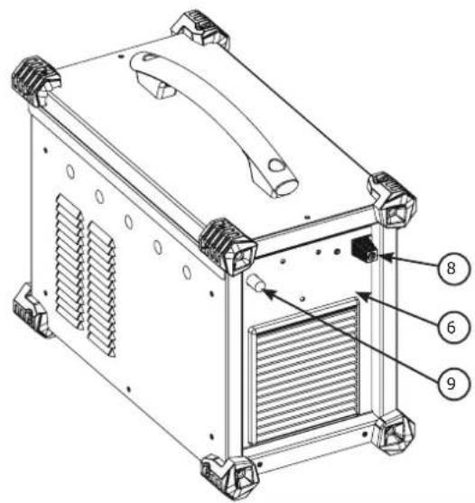
text_image
Technical diagram of a device with numbered components, likely an air conditioning unit or enclosure.
text_image
Technical diagram of a device with numbered components for identification
text_image
Technical diagram of a device with numbered parts labeled 6, 7, 8, and 9 pointing to internal components.FIG-2

text_image
INVERTER WELDER 888 A V S/Hz % A V JOB 7 5 10s 4 F(Hz) 0s 20s TIG - HF TIG - LIFT MMA 2T 4T 4T LOG %I + - Pulse F(Hz) %I Spot MMA Pulse F(Hz) 1 2 3AVERTISSEMENTS - RÈGLES DE SÉCURITÉ
CONSIGNE GÉNÉRALE

INSTALLATION – FONCTIONNEMENT PRODUIT
INTERFACE HOMME MACHINE (IHM) (FIG-2)
text_image
888 A V S/Hz % A V JOB TIG - HF TIG - LIFT MMA - + MMA Pulse FINDMMA (MMA PULSE)
text_image
888 A V S/Hz % A V JOB 10s 20s TIG - HF 2T TIG - LIFT 4T MMA 4T/OG %T - + Pulse (590%) Spottext_image
INVERTER WELDER 888 A V S/Hz % A V JOB 10r 20r TIG - HF 2T TIG - LIFT 4T MMA AT (sec. m) Pulse 2bit 1 Spot MMA Pulse 1text_image
888 A V S/Hz % A V JOB TIG - HF 2T TIG - LIFT 4T MMA Spot MMA Pattern INVERTER WELDERtext_image
Bouton principal T1 T2text_image
P L DB 1 5 2 4 2 3 P torch L torch DB torch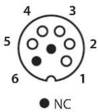
text_image
4 3 5 2 6 1 NC
text_image
DB torch L torch 2 3 4 2 5 1 DB + P torchMESSAGES D'ERREUR, ANOMALIES, CAUSES, REMÈDES
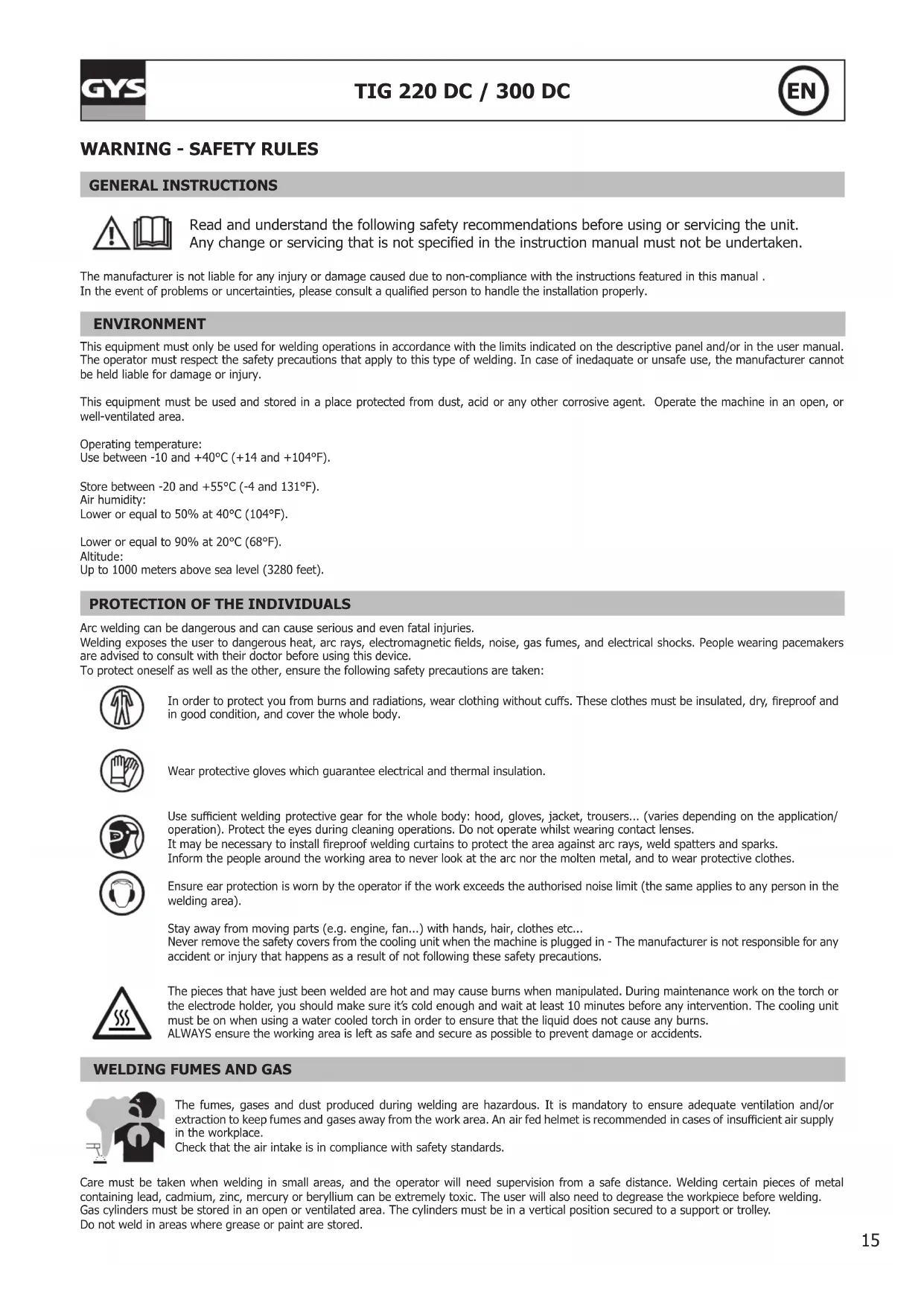
Read and understand the following safety recommendations before using or servicing the unit. Any change or servicing that is not specified in the instruction manual must not be undertaken.
The manufacturer is not liable for any injury or damage caused due to non-compliance with the instructions featured in this manual. In the event of problems or uncertainties, please consult a qualified person to handle the installation properly.
ENVIRONMENT
This equipment must only be used for welding operations in accordance with the limits indicated on the descriptive panel and/or in the user manual. The operator must respect the safety precautions that apply to this type of welding. In case of inedaquate or unsafe use, the manufacturer cannot be held liable for damage or injury.
This equipment must be used and stored in a place protected from dust, acid or any other corrosive agent. Operate the machine in an open, or well-ventilated area.
Operating temperature:
Use between -10 and +40°C (+14 and +104°F).
Store between -20 and +55°C (-4 and 131°F).
Air humidity:
Lower or equal to 50% at 40°C (104°F).
Lower or equal to 90% at 20°C (68°F).
Altitude:
Up to 1000 meters above sea level (3280 feet).
PROTECTION OF THE INDIVIDUALS
Arc welding can be dangerous and can cause serious and even fatal injuries.
Welding exposes the user to dangerous heat, arc rays, electromagnetic fields, noise, gas fumes, and electrical shocks. People wearing pacemakers are advised to consult with their doctor before using this device.
To protect oneself as well as the other, ensure the following safety precautions are taken:

In order to protect you from burns and radiations, wear clothing without cuffs. These clothes must be insulated, dry, fireproof and in good condition, and cover the whole body.

Wear protective gloves which guarantee electrical and thermal insulation.

Use sufficient welding protective gear for the whole body: hood, gloves, jacket, trousers... (varies depending on the application/operation). Protect the eyes during cleaning operations. Do not operate whilst wearing contact lenses.
It may be necessary to install fireproof welding curtains to protect the area against arc rays, weld spatters and sparks.
Inform the people around the working area to never look at the arc nor the molten metal, and to wear protective clothes.

Ensure ear protection is worn by the operator if the work exceeds the authorised noise limit (the same applies to any person in the welding area).
Stay away from moving parts (e.g. engine, fan...) with hands, hair, clothes etc...
Never remove the safety covers from the cooling unit when the machine is plugged in - The manufacturer is not responsible for any accident or injury that happens as a result of not following these safety precautions.
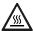
The pieces that have just been welded are hot and may cause burns when manipulated. During maintenance work on the torch or the electrode holder, you should make sure it's cold enough and wait at least 10 minutes before any intervention. The cooling unit must be on when using a water cooled torch in order to ensure that the liquid does not cause any burns.
ALWAYS ensure the working area is left as safe and secure as possible to prevent damage or accidents.
WELDING FUMES AND GAS

The fumes, gases and dust produced during welding are hazardous. It is mandatory to ensure adequate ventilation and/or extraction to keep fumes and gases away from the work area. An air fed helmet is recommended in cases of insufficient air supply in the workplace.
Check that the air intake is in compliance with safety standards.
Care must be taken when welding in small areas, and the operator will need supervision from a safe distance. Welding certain pieces of metal containing lead, cadmium, zinc, mercury or beryllium can be extremely toxic. The user will also need to degrease the workpiece before welding. Gas cylinders must be stored in an open or ventilated area. The cylinders must be in a vertical position secured to a support or trolley. Do not weld in areas where grease or paint are stored.
FIRE AND EXPLOSION RISKS

Protect the entire welding area. Compressed gas containers and other inflammable material must be moved to a minimum safe distance of 11 meters.
A fire extinguisher must be readily available.
Be careful of spatter and sparks, even through cracks. It can be the source of a fire or an explosion.
Keep people, flammable objects and containers under pressure at a safe distance.
Welding of sealed containers or closed pipes should not be undertaken, and if opened, the operator must remove any inflammable or explosive materials (oil, petrol, gas...).
Grinding operations should not be directed towards the device itself, the power supply or any flammable materials.
GAS BOTTLE

Gas leaking from the cylinder can lead to suffocation if present in high concentrations around the work area.
Transport must be done safely: Cylinders closed and product off. Always keep cylinders in an upright position securely chained to a fixed support or trolley.
Close the bottle after any welding operation. Be wary of temperature changes or exposure to sunlight.
Cylinders should be located away from areas where they may be struck or subjected to physical damage.
Always keep gas bottles at a safe distance from arc welding or cutting operations, and any source of heat, sparks or flames.
Be careful when opening the valve on the gas bottle, it is necessary to remove the tip of the valve and make sure the gas meets your welding requirements.
ELECTRIC SAFETY

The machine must be connected to an earthed electrical supply. Use the recommended fuse size.
An electrical discharge can directly or indirectly cause serious or deadly accidents.
Do not touch any live part of the machine (inside or outside) when it is plugged in (Torches, earth cable, cables, electrodes) because they are connected to the welding circuit.
Before opening the device, it is imperative to disconnect it from the mains and wait 2 minutes, so that all the capacitors are discharged.
Do not touch the torch or electrode holder and earth clamp at the same time.
Damaged cables and torches must be changed by a qualified and skilled professional. Make sure that the cable cross section is adequate with the usage (extensions and welding cables). Always wear dry clothes in good condition, in order to be insulated from the electrical circuit. Wear insulating shoes, regardless of the environment in which you work in.
EMC CLASSIFICATION

These Class A devices are not intended to be used on a residential site where the electric current is supplied by the public network, with a low voltage power supply. There may be potential difficulties in ensuring electromagnetic compatibility on these sites, because of the interferences, as well as radio frequencies.

- This equipment TIG 300 DC do not comply with IEC 61000-3-12 and is intended to be connected to private low-voltage systems interfacing with the public supply only at the medium- or high-voltage level. On a public low-voltage power grid, it is the responsibility of the installer or user of the device to ensure, by checking with the operator of the distribution network, which device can be connected.
- This equipment TIG 220 DC complies with the IEC 61000-3-12 standard.
This equipment TIG 220 DC complies with IEC 61000-3-11 if the power supply network's impedance at the electrical installation's connection point is inferior to the network's maximum admissible impedance Z_ = 0.29 Ohms.
ELECTROMAGNETIC INTERFERENCES

The electric currents flowing through a conductor cause electrical and magnetic fields (EMF). The welding current generates an EMF field around the welding circuit and the welding equipment.
The EMF fields may disrupt some medical implants, such as pacemakers. Protection measures should be taken for people wearing medical implants. For example, access restrictions for passers-by or an individual risk evaluation for the welders.
All welders should take the following precautions in order to minimise exposure to the electromagnetic fields (EMF) generated by the welding circuit::
- position the welding cables together – if possible, attach them;
- keep your head and torso as far as possible from the welding circuit;
- never enroll the cables around your body;
- never position your body between the welding cables. Hold both welding cables on the same side of your body;
- connect the earth clamp as close as possible to the area being welded;
- do not work too close to, do not lean and do not sit on the welding machine
- do not weld when you're carrying the welding machine or its wire feeder.

People wearing pacemakers are advised to consult their doctor before using this device.
Exposure to electromagnetic fields while welding may have other health effects which are not yet known.
RECOMMANDATIONS TO ASSES THE AREA AND WELDING INSTALLATION
Overview
The user is responsible for installing and using the arc welding equipment in accordance with the manufacturer's instructions. If electromagnetic disturbances are detected, it is the responsibility of the user of the arc welding equipment to resolve the situation with the manufacturer's technical assistance. In some cases, this remedial action may be as simple as earthing the welding circuit. In other cases, it may be necessary to construct an electromagnetic shield around the welding power source and around the entire piece by fitting input filters. In all cases, electromagnetic interferences must be reduced until they are no longer bothersome.
Welding area assessment
Before installing the machine, the user must evaluate the possible electromagnetic problems that may arise in the area where the installation is planned.
. In particular, it should consider the following:
a) the presence of other power cables (power supply cables, telephone cables, command cable, etc...) above, below and on the sides of the arc welding machine.
b) television transmitters and receivers ;
c) computers and other hardware;
d) critical safety equipment such as industrial machine protections;
e) the health and safety of the people in the area such as people with pacemakers or hearing aids;
f) calibration and measuring equipment
g) The isolation of the equipment from other machinery.
The user will have to make sure that the devices and equipments that are in the same room are compatible with each other. This may require extra precautions;
h) make sure of the exact hour when the welding and/or other operations will take place.
The surface of the area to be considered around the device depends on the building's structure and other activities that take place there. The area taken in consideration can be larger than the limits determined by the companies.
Welding area assessment
Besides the welding area, the assessment of the arc welding systems installation itself can be used to identify and resolve cases of disturbances. The assessment of emissions must include in situ measurements as specified in Article 10 of CISPR 11. In situ measurements can also be used to confirm the effectiveness of mitigation measures.
RECOMMENDATION ON METHODS OF ELECTROMAGNETIC EMISSIONS REDUCTION
a. National power grid: The arc welding machine must be connected to the national power grid in accordance with the manufacturer's recommendation. If interferences occur, it may be necessary to take additional preventive measures such as the filtering of the power supply network. Consideration should be given to shielding the power supply cable in a metal conduit. It is necessary to ensure the shielding's electrical continuity along the cable's entire length. The shielding should be connected to the welding current's source to ensure good electrical contact between the conduct and the casing of the welding current source..
b. Maintenance of the arc welding equipment: The arc welding machine should be submitted to a routine maintenance check according to the manufacturer's recommendations. All accesses, service doors and covers should be closed and properly locked when the arc welding equipment is on.. The arc welding equipment must not be modified in any way, except for the changes and settings outlined in the manufacturer's instructions. The spark gap of the arc start and arc stabilization devices must be adjusted and maintained according to the manufacturer's recommendations.
c. Welding cables: Cables must be as short as possible, close to each other and close to the ground, if not on the ground.
d. Electrical bonding : consideration should be given to bonding all metal objects in the surrounding area. However, metal objects connected to the workpiece increase the risk of electric shock if the operator touches both these metal elements and the electrode. It is necessary to insulate the operator from such metal objects.
e. Earthing of the welded part: When the part is not earthed - due to electrical safety reasons or because of its size and its location (which is the case with ship hulls or metallic building structures), the earthing of the part can, in some cases but not systematically, reduce emissions. It is preferable to avoid the earthing of parts that could increase the risk of injury to the users or damage other electrical equipment. If necessary, it is appropriate that the earthing of the part is done directly, but in some countries that do not allow such a direct connection, it is appropriate that the connection is made with a capacitor selected according to national regulations.
f. Protection and plating : The selective protection and plating of other cables and devices in the area can reduce perturbation issues. The protection of the entire welding area can be considered for specific situations.
TRANSPORT AND TRANSIT OF THE WELDING MACHINE

The machine is fitted with handle to facilitate transportation. Be careful not to underestimate the machine's weight. The handle(s) cannot be used for slinging.
Do not use the cables or torch to move the machine. The welding equipment must be moved in an upright position.
Never lift the machine while there is a gas cylinder on the support shelf. A clear path is available when moving the item. Do not place/carry the unit over people or objects.
EQUIPMENT INSTALLATION
- Put the machine on the floor (maximum incline of 10^ ).
- Ensure the work area has sufficient ventilation for welding, and that there is easy access to the control panel.
- The machine must not be used in an area with conductive metal dusts.
- The machine must be placed in a sheltered area away from rain or direct sunlight.
• The machine protection level is IP21, which means : - Protection against access to dangerous parts from solid bodies of a ≥12.5mm diameter and,
- Protection against vertically falling drops.
- The machine protection level is IP23, which means :
- Protection against access to dangerous parts from solid bodies of a ≥12.5mm diameter and,
- Protection against the rain inclined at 60% towards the vertical.
These devices can be used outside in accordance with the IP23 protection index.
The power cables, extensions and welding cables must be fully uncoiled to prevent overheating.

The manufacturer does not incur any responsibility regarding damages to both objects and persons that result from an incorrect and/or dangerous use of the machine.
MAINTENANCE / RECOMMENDATIONS


- Maintenance should only be carried out by a qualified person. Annual maintenance is recommended.
- Ensure the machine is unplugged from the mains, and wait for two minutes before carrying out maintenance work. DANGER
High Voltage and Currents inside the machine.
- Remove the casing 2 or 3 times a year to remove any excess dust. Take this opportunity to have the electrical connections checked by a qualified person, with an insulated tool.
- Regularly check the condition of the power supply cable. If the power cable is damaged, it must be replaced by the manufacturer, its after sales service or an equally qualified person.
- Ensure the ventilation holes of the device are not blocked to allow adequate air circulation.
- Do not use this equipment to thaw pipes, to charge batteries, or to start any engine.
INSTALLATION – PRODUCT OPERATION
Only qualified personnel authorized by the manufacturer should perform the installation of the welding equipment. During set up, the operator must ensure that the machine is unplugged. Connecting generators in a series or a parallel circuit is forbidden.
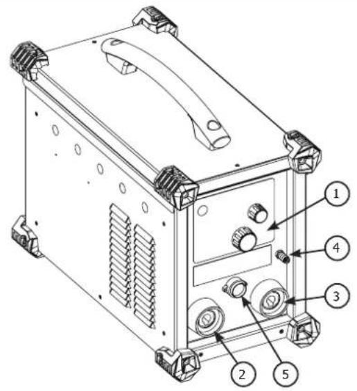
HARDWARE DESCRIPTION (FIG-1)
These TIGs are inverter welding power sources for direct current (DC) refractory electrode welding (TIG) and shielded metal arc welding (MMA). The TIG process requires gas shielding (Argon).
The MMA process can weld any type of electrode: rutile, basic, stainless steel and cast iron.
These TIGs can be equipped with a manual remote control (ref. 045675) or a foot pedal (ref. 045682).
The TIG 300 DC can be equipped with an automatic command (CONNECT-5).
1- Keyboard + buttons 5- Trigger connection
2- + polarity plug 6- Remote control connection
3- - polarity plug 7- ON / OFF switch
4- Gas connection for torch 8- Power supply cable
9- Gas inlet
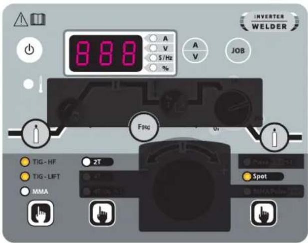
CONTROL BOARD (IHM) (FIG-2)
1- Process section 5- Thermal protection indicator
2- Trigger mode selection 6- Display and options
3- Process options selection 7- Sleep button
4- Welding parameters settings.
POWER SUPPLY – STARTING UP
- The TIG 300 DC is supplied with a 5-pole (3P+N+PE) 400V 16A three-phase plug of type EN 60309-1 and is supplied from a 400V (50 - 60 Hz) three-phase electrical installation WITH earth. This equipment must only be used on a three-phase four-wire power system with the neutral connected to earth. The TIG 220 DC is delivered with a single-phase 3-pole (P+N+PE) 230V 16A CEE17 plug, is equipped with a «Flexible Voltage» system and is supplied on an electrical installation with earth between 110V and 240V (50 - 60 Hz).
The effective absorbed current (I1eff) is indicated on the welding current source and for the maximum operating conditions. Check that the power supply and its protection (fuse and/or circuit breaker) are compatible with the current required in use. In some countries, it may be necessary to change the plug to allow use at maximum conditions. The user must ensure that the plug is accessible. - The welding current source goes into protection if the supply voltage is less than or greater than 15% of the specified voltage(s) (a fault code will appear on the keyboard display).
- The TIG 300 DC is switched on by turning the on/off switch (7) to position I, conversely, it is switched off by turning to position O. The TIG 220 DC is switched on by pressing the standby button. Caution! Never switch off the power supply when the welding current source is under load.
- Fan behaviour: In MMA mode, the fan runs continuously. In TIG mode, the fan runs only during the welding phase and then stops after cooling
- Warning: Increasing the length of the torch or return cables beyond the maximum length specified by the manufacturer will increase the risk of electric shock.
CONNECTION ON A GENERATOR
The machine can work with generators as logn as the auxiliary power matches these requirements :
- The voltage must be AC, always superior to 400Vac ±15%, and the peak voltage below 700V,
- The frequency must be between 50 and 60 Hz.
It is imperative to check these requirements as several generators generate high voltage peaks that can damage these machines.
USE WITH EXTENSION CABLES
All extension cables must have an adequate size and section, relative to the machine's voltage. Use an extension that complies with national safety regulations.
| Current input | Length - Extension selection | ||
| < 45m < 100m | |||
| TIG 300 DC 400V 2.5 mm ^2 | |||
| TIG 220 DC | 230V 2.5 mm ^2 | ||
| 110V 2.5 mm ^2 | 4 mm ^2 | ||
SYMBOLS & MENUS
| FUNCTION PICTOGRAM | TIG DC | MMA | Comment | |
| HF ignition X TIG process with HF ignition HF | ||||
| Lift ignition X TIG process with LIFT ignitionT | ||||
Pre-gas X Time to purge the t  | t the area | with gas | before ignition | |
| Up slope current X Up slope current I | ||||
| Welding current X Welding current I | ||||
| Courant froid | % I | X | Second welding current or «cold» current in standard 4TLOG or in PULSE mode | |
| PULSE Frequency | F(Hz) | X | X | PULSATION frequency of the PULSE mode (Hz) |
| Down slope current |  | X | Down slope current to minimum current, I Stop (S) to prevent weld defects and craters. | |
| Post gas |  | X | Length of time in which gas is released after the arc has stopped. It protects the weld pool and the electrode against oxidization when the metal is cooling (S). | |
| HotStart | X | Adjustable overcurrent at the beginning of the welding (%) | ||
| ArcForce |  | X | Overcurrent delivered to avoid sticking when the electrode enters the welding pool | |
| TIG PULSE X Pulse mode | ||||
| TIG SPOT | -  | X Spot mode | ||
| MMA PULSE | X | MMA process in PULSE mode | ||
| 2T |  | X 2 time torch mode | ||
| 4T | X 4 time torch mode | |||
| 4T LOG X 4 time LOG torch mode |  | |||
| Ampere (unit) | X | X | Amperes unit for welding current settings | |
| Volt (unit) | X | X | Volt unit for displaying welding voltage | |
| Second or Hertz (units) |  | X | X | Seconds or Hertz unit for time or frequency settings |
| Percentage (unit) | X | X | Percentages unit for proportionate settings | |
| Display switch A or V | A/V | X | X | Switches the display of voltage or current during and after welding |

| Program menu access X X Access to configuration | menu (SAVE, JOB, ...) | ||
| Thermal protection X X Standard symbol to indicate the thermal protection state | |||
| Sleep mode X X Sleep mode | |||
ELECTRODE WELDING (MMA)
CONNECTIONS AND RECOMMENDATIONS
- Connect the cables, electrode holder and earth clamp in the connectors,
- Respect the welding polarities and intensities indicated on the electrodes boxes,
- Remove the electrode from the electrode holder when the machin is not in use.

text_image
888 A V S / Hz % A V JOB INVERTER WELDER TIG - HF TIG - LIFT MMA 21° 45° 89 Hz - + MMA Pulse (Fire)MMA (MMA PULSE)
The grey areas are not useful for this mode.
| Adjustable values 0 - 100% 0 - 100% | ||
TIG WELDING WITH INERT GAS (TIG MODE)
CONNECTIONS AND RECOMMENDATIONS
Connect the earth clamp to the positive connector (+).
Connect the torch to the negative plug (−), the trigger cable and the gas hose.
Ensure that the torch is equipped and ready to weld, and that the consummables (Vise grip, ceramic gas nozzle, collet and collet body) are not damaged.
TIG WELDING PROCESSES

text_image
888 A V S/Hz % A V JOB 10s 20s TIG-HF 2T TIG-LIFT 4T MMA 4TLOG %I - + Pulse 5960 %I SpotTIG
The grey areas are not useful for this mode.

text_image
888 A V S / Hz % A V JOB INVERTER WELDER 10s 20s TIG - HF 2T TIG - LIFT 4T MMA Pulse Split %1 Spot ATTG - %1 MMA PulseTIG PULSE
The grey areas are not useful for this mode.
• TIG DC
This welding mode in direct current (DC) is designed for ferrous metal such as steel, stainless steel or even copper and its alloys.
• TIG DC Pulsed
This pulse welding mode chains high current pulses (I, welding pulse) then low current pulses (I_cold, pulses to cool the piece). This pulse mode allows to assemble pieces while limiting high temperatures.
Example :
The I welding current is set to a 100A and % (I_cold) = 50%, thus a Cold current of = 50% x 100A = 50A. F(Hz) is set to 10Hz, the signal period will be 1/10Hz = 100ms.
Every 100ms, a 100A pulse then a 50A pulse will succeed each other.
The choice of frequency
- If welding with TIG electrodes, then F(Hz) synchronised to the gesture,
- If thin plate without TIG electrodes (< 8/10 mm), F(Hz) >> 10Hz
- If special metal requiring a welding pool sweep for degasing, then F(Hz) >> 100Hz
• Tack weld feature SPOT
text_image
888 A V S/Hz % A V JOB TIG-HF 2T TIG-LIFT MMA Spot INVERTER WELDERTIG SPOT
The grey areas are not useful for this mode.
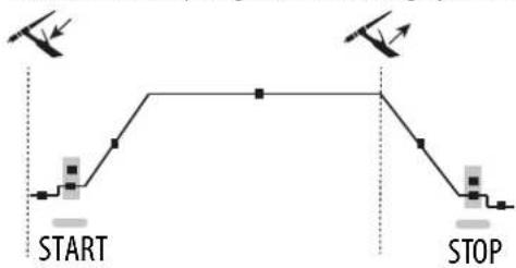
• TIG DC - Advanced menu
The Start and Stop stages of the welding cycle can be set.
flowchart
graph TD
    A["Start"] --> B["Step 1"]
    B --> C["Step 2"]
    C --> D["Stop"]
    D --> E["Step 3"]
    E --> F["Stop"]
To access these advanced parameters, press and hold the «JOB» button for more than 3 seconds until SET and then UP are displayed continuously. Once the button is released, in the drop-down menu, go to «SET» using the central wheel and validate by pressing the «JOB» button.
By scrolling the wheel, the following advanced settings can be accessed:
| Parameter Description Setting | |
| I_Start step current at welding start 10% - 200% | |
| T_Start time of the welding start stage 0s - 10s | |
| I_Stop stop welding stage current 10% - 100% | |
| T_Stop time of welding stop stage 0s - 10s |
The parameter to be modified is selected by pressing the «JOB» button. Once the modification has been made with the central wheel (I), it is validated by pressing the «JOB» button.
The exit of the advanced menu is done by validation «ESC».
SELECT STRIKING MODE
HF TIG: High Frequency start without contact
TIG LIFT : Contact start (for environments sensitive to HF disturbances).

text_image
Touch Switch Lift Pré Gaz 0.5s <1s1- Touch the work-piece with the electrode
2- Press the trigger on the torch
3- Pull back the torch to lift the electrode.
 |  |  |
| √ | √ | √ |
TORCHES AND TRIGGER MODES
For the 1 button torch, the button is called «main button».
For the 2 buttons torch, the first button is called «main button» and the second button is called «secondary button».
2T MODE
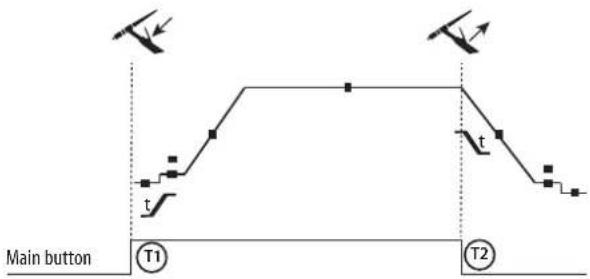
text_image
Main button T1 T24T MODE

flowchart
graph TD
    A["Main button T1"] --> B["T2"]
    B --> C["T3"]
    C --> D["T4"]
    style A fill:#f9f,stroke:#333
    style B fill:#ccf,stroke:#333
    style C fill:#cfc,stroke:#333
    style D fill:#fcc,stroke:#333
T1 - The main button is pressed, the welding cycle starts (PreGas, I_Start, UpSlope and welding).
T2 - The main button is released, the welding cycle is stopped (DownSlope, I_Stop, PostGas).
For the double button torch and in 2T mode only, the secondary button works like the main button.
T1 - The main button is pressed, the cycle starts at PreGas and stops in the I_Start phase.
T2 - The main button is released, the cycle continues in UpSlope and in welding.
T3 - The main button is pressed, the cycle switches to DownSlope and stops in I_Stop.
T4 - The main button is released, the cycle ends with PostGas.
Nb : for torches, double button and double button with potentiometer => command « up/welding current » and active potentiometer, command «low » inactive.
4T MODE log

text_image
Main button or Secondary button T1 T2 T3 T4 t ≥0.5s<0.5s<0.5sT1 - The main button is pressed, the cycle starts at PreGas and stops in the I Start phase.
T2 - The main button is released, the cycle continues in UpSlope and in welding.
LOG: this mode is used during welding :
- A brief press of the main button (<0.5s), the current switches from I welding current to I cold and vice versa.
- the secondary button is kept pressed, the weldin current switches from I welding current to I cold
- the secondary button is kept released, the current switched from I cold to I welding current.
T3 - A long press on the main button (>0.5s), the cycle switches to DownSlope and stops in the I_Stop phase.
T4 - The main button is released, the cycle finishes with PostGas.
For this mode it may be convenient to use the dual button torch option or dual button with potentiometer. The «up» command keeps the same function as the single button or trigger torch. The «down» button can, when pressed, switch to the cold current. The potentiometer of the torch, where available, allows control of the welding current from 50% to 100% of the value displayed.
RECOMMENDED COMBINATIONS
| Process Type HF Lift | |||
| TIG DC | STD | √ | √ |
| PULSE | √ | √ | |
| SPOT - | √ | ||
| MMA | STD |
| PULSE |
| DC |  | Current (A) Electrode (mm) Shroud (mm) | Argon flow rate (L/min) | |
| 0.3 - 3 mm 5 - 75 | 1 6.5 6 - 7 | |||
| 2.4 - 6 mm 60 - 1 | 50 1.6 8 6 - 7 | |||
| 4 - 8 mm 100 - 2 | 200 2 9.5 7 - 8 | |||
| 6.8 - 8.8 mm 170 - | 250 2.4 11 8 - 9 | |||
| 9 - 12 mm 225 - 3 | 300 3.2 12.5 | 9 - 10 |
ELECTRODE GRINDING
To optimise the welding process, it is recommended to grind the electrode prior to welding as described below:

text_image
d LL = 3 x d for a low current.
L = 3 x d for a high current
SAVE AND LOAD WELDING SETTINGS
There are 10 memories in MMA and 10 in DC TIG.
Menu is accessed with the «JOB» button.
Save settings
Once in program mode, select IN and press the access button.
Slect a program from P1 to P10. Press the access button and the current setting is saved.
Load an existing setting
Once in program mode, select OUT and press the access button.
Slect a program from P1 to P10. Press the access button and the setting is loaded.
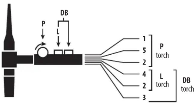
COMMAND TRIGGER CONNECTOR
text_image
P L DB 1 5 2 4 2 3 P torch L torch DB torch
text_image
4 3 5 2 6 1 NC
text_image
3 DB torch 4 L torch 2 2 5 DB + P torch 1Cabling diagram for the SRL18 torch.
Electric diagram according to torch type.
| Torch type | Wire description | Pin | ||
| Torch 2 triggers + poten- tiometer | Torch 2 triggers Torch 1 | trigger | Common/Earth | 2 (green) |
| Switch trigger 1 | 4 (white) | |||
| Switch trigger 2 | 3 (brown) | |||
| Common/Potentio- meter earth | 2 (grey) | |||
| 5 V | 1 (yellow) | |||
| Cursor | 5 (pink) | |||
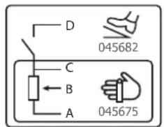
REMOTE CONTROL
The remote control operates in TIG mode and in MMA.

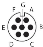
text_image
D 045682 C B A 045675ref. 045699 External view Electric diagram according to remote control type.
Connection
1- Plug the remote control into the connection at the back of the machine.
2- The machine will detect automatically the remote control and open a selection menu:
Foot pedal selection.
Remote control with potentiometer selection.
CONNECT-5 (automate-robot) selection.
Remote control is connected but inactive.
Connection
The material is equipped with a female socket for a remote control.
The specific 7 pin male plug (option ref. 045699) enables connection to the different types of manual remote control or foot pedal. For the cabling layout, please see the diagram below.
| REMOTE CONTROL TYPE Wire description Pin | ||||
| CONNECT-5 | Foot pedal Manual | remote control | 10V A | |
| Cursor B | ||||
| Common/Earth C | ||||
| Switch D | ||||
| AUTO-DETECT E | ||||
| ARC ON F | ||||
| REG I G | ||||
Operating :
- Manual remote control (option ref. 045675):
The remote control enables the variation of current from 50% to 100% of the set intensity. In this configuration, all modes and functions of the machine are accessible and can be set.
• Pedal (option ref. 045682):
The pedal control enables variation of the current from the minimum set current to a 100% of the set intensity.
In TIG mode, the machine will only operate in two-stage welding (2T mode). The upslope and downslope are not automatic, and are controlled by the User with the foot pedal.
- Connect 5 - automaton mode (TIG 300 DC only) :
This mode enables to pilot the TIG 300 DC from a console or from an automaton due to 5 pre-saved programs.
As the foot pedal, the «Switch (D)» enables to start or stop welding according to the chosen cycle. The voltage value for the «slider (B)» matches a program or the actual statut.
This voltage must be between 0 and 10V (step of 1.6V) which is linked to a program reminder:
- Actual status : 0 - 1.6 V
- Program 1 : 1.7 - 3.3 V
- Program 2 : 3.4 - 5.0 V
- Program 3 : 5.1 - 6.6 V
- Program 4 : 6.7 - 8.3 V
- Program 5 : 8.4 - 10.0 V
An additional potentiometer enables to change the current (+/- 15%) either whilst welding or not. The information ARC ON (arc presence) enables the automaton to synchronise itself (Pull Up 100kΩ entry, automaton side). Put the pin AUTO_DETECT to the earth enables to start the product without going through the window where you can select the type of remote control used.
The 5 programs loaded correspond to the frist 5 saved programs (P1 to P5).
COOLING UNIT (OPTION)
| TIG 220 DC | ||
| WCU0.5kW_A | P 1L/min = 500WCapacity = 1.5 LU1 = 185V - 265V | When working within the 185V-265V power supply range, the cooling unit is controlled by the welding machine,When working within the 85V-185V power supply range, the cooling unit is always switched off. |
| WCU1kW_A | P 1L/min = 1000WCapacity = 3 LU1 = 85V - 265V | The cooling unit is controlled by the welding machine throughout the 85V-265V power supply range. |
| TIG 300 DC | ||
| WCU1kW_B | P 1L/min = 1000WCapacity = 3 LU1 = 400V +/- 15% | The cooling unit is controlled by the welding machine throughout the power supply range. |
This machine may be connected to a cooling system for the cooling of the water torch. In the OPTION menu, this cooling unit system can be deactivated.
A 3 second press on the «JOB» button allows access to the cooling unit system menu.

Make sure that the cooling unit is turned off before disconnecting the inlet and outlet hoses for torch liquid.
The coolant is harmful and irritates the eyesm the mucus membranes and the skin. Hot liquid may cause burns.
TROUBLESHOOTING
This device integrates a default management system.
A series of messages displayed on the control board allows for a fault and anomalies diagnosis.
| ANOMALIES AND MMI DISPLAY | CAUSES SOLUTIONS | |
| WELDING MACHINE | ||
| « dEF » « 1 » Communication error | Check the internal cabling between the MMI and the PCB. | |
| « dEF » « 2 » Faulty MMI buttons Replace the MMI. | ||
| « dEF » « 3 » | Faulty torch(es) trigger(s) / button(s) | Replace the torch. |
| « dEF » « 4 » Foot pedal switch always active or faulty | Replace the pedal and check that the switch is not stuck. | |
| « E r r » « Co.5 » | In automaton mode, a command default is detected. | Check the automaton's cabling. |
| « --- » | An overvoltage was detected on the electrical distribution network. | A power surge is the origin of the message and originates from a motor overload, lightning... |
| « P h » | 1 phase missing from the three phase network. | The installation must be three phase (3P+N+E) |
| « d E » | A voltage unbalance was detected on the electrical distribution network. | Call your supplier. |
| WELDING MACHINE + COOLING UNIT | ||
| « Pb.1 » Cooling unit detection default. | Check the connectors between the welding current source. | |
| « Pb.2 » Cooling liquid supply default. Fill the cooling unit's tank. | ||
| « Pb.3 » Cooling liquid flow default. | Check the liquid flow's between the unit and the torch. | |
WARRANTY
The warranty covers faulty workmanship for 2 years from the date of purchase (parts and labour).
The warranty does not cover:
- Transit damage.
- Normal wear of parts (eg. : cables, clamps, etc..).
- Damages due to misuse (power supply error, dropping of equipment, disassembling).
- Environment related failures (pollution, rust, dust).
In case of failure, return the unit to your distributor together with:
- The proof of purchase (receipt etc ...)
- A description of the fault reported
text_image
888 A V S/Hz % A V JOB INVERTER WELDER TIG - HF TIG - LIFT MMA - + MMA Pulse WireE-HAND (MMA PULSE)
text_image
888 A V 5/Hz % A V JOB 10s 20s TIG-HF 2T TIG-LIFT 4T MMA 4T/OG %I - + Pulse 3960% I Spottext_image
888 A V S/Hz % A V JOB 10s 20s TIG - HF 2T TIG - LIFT 4T MMA Pulse 23% 1% Spot MMA Pulltext_image
888 A V S/Hz % A V JOB TIG-HF 2T TIG-LIFT 41 MMA Spot MMA Pulse INVERTER WELDERtext_image
P DB L 1 5 2 4 2 3 L torch DB torch NC 4 3 5 2 6 1 DB torch L torch 2 3 4 2 5 1 DB + P torch- Connect 5 - Automatikmodus (nur WIG 300 DC):
text_image
888 A V S/Hz % A V INVERTER WELDER % I LA TIG - HF TIG - LIFT MMA ATLDO - HL + Pulse 100% Spot MMA Pulse FINGtext_image
888 A V S/Hz % A V JOB 10s 20s TIG - HF 2T TIG - LIFT 4T MMA 4T/OG %T Pulse (590%) Spottext_image
INVERTER WELDER 888 A V S /Hz % A V JOB 10r 20r TIG - HF 2T TIG - LIFT 4T MMA ATG - 11 Pulse 3.90 % Spot MMA Pulsetext_image
888 A V S/Hz % A V JOB TIG - HF 2T TIG - LIFT MMA Spot MMA Pulsetext_image
Bouton principal T1 T2text_image
P L DB 1 5 2 4 2 3 P torch L torch DB torch
text_image
4 3 5 2 6 1 NC
text_image
DB torch L torch 2 3 4 2 5 1 DB + P torchtext_image
888 A V S/Hz % A V JOB INVERTER WELDER TIG - HF TIG - LIFT MMA - + MMA Pulse (pH) I II IIIMMA (MMA PULSE)
text_image
888 A V S/Hz % A V JOB 10s 20s 0s I TIG-HF 2T TIG-LIFT 4T MMA 4TLOG %I + Pulse Formo %I Spottext_image
INVERTER WELDER 8 8 8 A V S/Hz % A V JOB I % I 10s 20s TIG - HF 2T TIG - LIFT 4T MMA Pulse (50%) % Spot Mixer Pulsetext_image
888 A V S/Hz % A V JOB TIG-HF 2T TIG-LIFT 4T MMA Spot MAX/Min/Max/Mintext_image
DB P L 1 5 2 4 2 3 L torch DB torch NC 4 3 5 2 6 1 DB torch L torch 3 4 2 2 5 1 DB + P torchWAARSCHUWING - VEILIGHEIDSINSTRUCTIES
ALGEMENE INSTRUCTIES

INTERFACE HUMANE MACHINE (IHM) (FIG-2)
LASSEN MET BEKLEDE ELEKTRODE (MODE MMA)
AANSLUITING EN ADVIEZEN
text_image
888 A V S/Hz % A V JOB INVERTER WELDER TIG - HF TIG - LIFT MMA - + MMA Pulse FWDtext_image
888 A V S/Hz % A V JOB 10s 20s TIG - HF 2T TIG - LIFT 4T MMA 4T/OG %T Pulse (5900 %) Spottext_image
INVERTER WELDER 888 A V S/Hz % A V JOB 10s 20s TIG - HF 2T TIG - LIFT 4T MMA AT (On, n-1) Pulse 2(Sh) %1 Spot Mixer Pulsetext_image
888 A V S / Hz % A V JOB TIG - HF 2T TIG - LIFT MMA Spot INVERTER WELDERtext_image
Bouton principal T1 T2text_image
P DB L 1 5 2 4 2 3 L torch P torch DB torch NC 4 3 5 2 6 1 DB torch L torch 2 3 4 2 5 1 DB + P torch- Connect 5 - PLC modus (alleen TIG 300 DC):
SALDATURA AD ELETTRODO RIVESTITO (MODALITÀ MMA)
COLLEGAMENTO E CONSIGLI
I PROCESSI DI SALDATURA TIG

text_image
INVERTER WELDER 888 A V 5/Hz % A V JOB 10s 20s I TIG - HF 2T TIG - LIFT 4T MMA 4TLOG %I - + Spot Pulse 1000 % Itext_image
INVERTER WELDER 888 A V 5/Hz % A V JOB 10s 20s F### 0s TIG-HF 2T TIG-LIFT 4T MMA Pulse Rate %1 Spot MMA Rate 202text_image
Bouton principal T1 T2text_image
P L DB 1 5 2 P torch 4 2 L torch 3 DB torch 4 3 5 2 6 1 ● NC