Autopulse 320T1 - Welding machine GYS - Free user manual and instructions
Find the device manual for free Autopulse 320T1 GYS in PDF.
| Product type | Synergic MIG/MAG semi-automatic welding machine |
| Brand | GYS |
| Model | Autopulse 320T1 |
| Power supply | 400 V three-phase (50-60 Hz) or 208-240 V three-phase depending on version |
| Max welding current | 320 A (estimated from the reference) |
| Duty cycle | Variable according to current, up to 60% at 320 A (10 min cycle, 40°C) |
| Supported wire diameters | Steel: 0.6 to 1.2 mm; Stainless steel: 0.8 to 1.2 mm; Aluminum: 0.8 to 1.2 mm; CuSi/CuAl: 0.8 to 1.2 mm |
| Welding types | Synergic MIG/MAG, modes: Standard, Pulsed, Cold Pulse, Manual, Spot/Delay |
| Shielding gas | Ar+CO2 (steel/stainless), Pure Ar (aluminum, brazing) |
| Gas flow rate | 8-15 L/min (steel), 15-20 L/min (aluminum), 12-15 L/min (pulsed) |
| Cooling | Fan cooled (air) |
| Protection rating | IP23 |
| Operating temperature | -10°C to +40°C |
| Storage temperature | -20°C to +55°C |
| Connectivity | USB port for updates and data transfer |
| User interface | HMI screen with knobs and push buttons |
| Safety functions | Thermal protection, overvoltage/undervoltage, ground current detection, interface lock |
| Maintenance | Regular dusting, check connections, wire feeder calibration |
| Common spare parts | Push-Pull torches, Spool Gun, drive rolls, liners, contact tips, nozzles |
| Warranty | 2 years parts and labor (excluding wear and misuse) |
| Approximate weight | ~35 kg (estimate) |
Frequently Asked Questions - Autopulse 320T1 GYS
User questions about Autopulse 320T1 GYS
0 question about this device. Answer the ones you know or ask your own.
Ask a new question about this device
Download the instructions for your Welding machine in PDF format for free! Find your manual Autopulse 320T1 - GYS and take your electronic device back in hand. On this page are published all the documents necessary for the use of your device. Autopulse 320T1 by GYS.
USER MANUAL Autopulse 320T1 GYS
FR 02-06/7-20/94-104
EN 02-06/21-32/94-104
DE 02-06/33-45/94-104
ES 02-06/46-57/94-104
RU 02-06/58-69/94-104
NL 02-06/70-81/94-104
IT 02-06/82-93/94-104
AUTOPULSE T1-T3
INSTALLATION - FONCTIONNEMENT PRODUIT
INTERFACE HOMME-MACHINE (IHM)

| Current input Extension lead section (<45m) | |
| 400 V | 2.5 mm² |
INSTALLATION DE LA BOBINE

ANOMALIES, CAUSES, REMÉDES
CONDITIONS DE GARANTIE
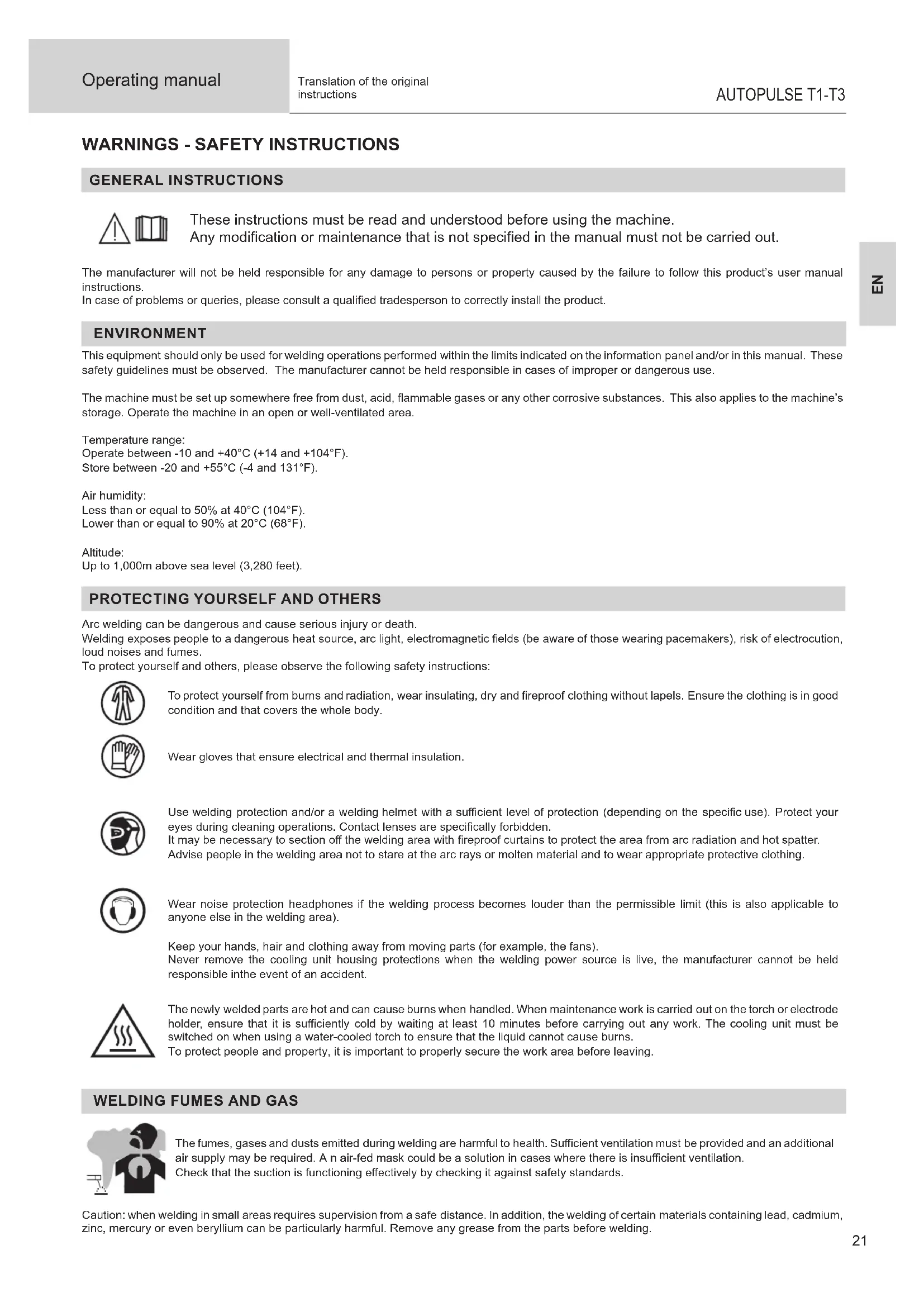
WARNING - SAFETY INSTRUCTIONS
GENERAL INSTRUCTIONS
These instructions must be read and understood before using the machine. Any modification or maintenance that is not specified in the manual must not be carried out.
The manufacturer will not be held responsible for any damage to persons or property caused by the failure to follow this product's user manual instructions.
In case of problems or queries, please consult a qualified tradesperson to correctly install the product.
ENVIRONMENT
This equipment should only be used for welding operations performed within the limits indicated on the information panel and/or in this manual. These safety guidelines must be observed. The manufacturer cannot be held responsible in cases of improper or dangerous use.
The machine must be set up somewhere free from dust, acid, flammable gases or any other corrosive substances. This also applies to the machine's storage. Operate the machine in an open or well-ventilated area.
Temperature range:
Operate between -10 and +40^ (+14 and +104^)
Store between -20 and +55^ (-4 and 131^
Air humidity:
Less than or equal to 50% at 40^ (104^)
Lower than or equal to 90% at 20^ (68^)
Altitude:
Up to 1,000m above sea level (3,280 feet).
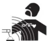
PROTECTING YOURSELF AND OTHERS
Arc welding can be dangerous and cause serious injury or death.
Welding exposes people to a dangerous heat source, arc light, electromagnetic fields (be aware of those wearing pacemakers), risk of electrocution, loud noises and fumes.
To protect yourself and others, please observe the following safety instructions:

To protect yourself from burns and radiation, wear insulating, dry and fireproof clothing without lapels. Ensure the clothing is in good condition and that covers the whole body.

Wear gloves that ensure electrical and thermal insulation.

Use welding protection and/or a welding helmet with a sufficient level of protection (depending on the specific use). Protect your eyes during cleaning operations. Contact lenses are specifically forbidden.
It may be necessary to section off the welding area with fireproof curtains to protect the area from arc radiation and hot spatter. Advise people in the welding area not to stare at the arc rays or molten material and to wear appropriate protective clothing.

Wear noise protection headphones if the welding process becomes louder than the permissible limit (this is also applicable to anyone else in the welding area).
Keep your hands, hair and clothing away from moving parts (for example, the fans).
Never remove the cooling unit housing protections when the welding power source is live, the manufacturer cannot be held responsible inthe event of an accident.
The newly welded parts are hot and can cause burns when handled. When maintenance work is carried out on the torch or electrode holder, ensure that it is sufficiently cold by waiting at least 10 minutes before carrying out any work. The cooling unit must be switched on when using a water-cooled torch to ensure that the liquid cannot cause burns.
To protect people and property, it is important to properly secure the work area before leaving.
WELDING FUMES AND GAS

The fumes, gases and dusts emitted during welding are harmful to health. Sufficient ventilation must be provided and an additional air supply may be required. An air-fed mask could be a solution in cases where there is insufficient ventilation.
Check that the suction is functioning effectively by checking it against safety standards.
Caution: when welding in small areas requires supervision from a safe distance. In addition, the welding of certain materials containing lead, cadmium, zinc, mercury or even beryllium can be particularly harmful. Remove any grease from the parts before welding.
Gas cylinders should be stored in open or well-ventilated areas. They should be kept in an upright position and kept on a cart or trolley. Welding should not be undertaken near grease or paint.
FIRE AND EXPLOSION RISKS

Fully protect the welding area, flammable materials should be kept at least 11 metres away. Fire fighting equipment should be present in the vicinity of welding operations.
Beware the expulsion of hot spatter or sparks, even through cracks, which can cause fires or explosions. Keep people, flammable objects and pressurised containers at a safe distance.
Do not weld in closed containers or tubes. If they are open, remove any flammable or explosive materials (oil, fuel, etc.) before welding. Grinding work must not be directed towards the source of the welding current or towards any flammable materials.
GAS CYLINDERS

Gas escaping from the cylinders can cause suffocation if it becomes concentrated in the welding area (ventilate well). Transporting the machine must be done safely: gas cylinders must be closed and the welding power source turned off. They should be stored upright and supported to reduce the risk of falling.
Tightly close the bottle between uses. Beware of temperature changes and sun exposure.
The bottle should not come into contact with flames, electric arcs, torches, earth clamps or any other sources of heat.
Keep away from electrical and welding circuits and never weld a pressurised cylinder.
When opening the cylinder valve, keep your head away from the valve and ensure that the gas being used is suitable for the welding process.
ELECTRICAL SAFETY

The electrical network used must be earthed. Use the recommended fuse size chosen from the information table. Electric shocks can cause serious direct and indirect accidents or even death.
Never touch live parts connected to the live current, either inside or outside the power source casing unit (torches, clamps, cables, electrodes), as these items are connected to the welding circuit.
Before opening the welding machine's power source, disconnect it from the mains and wait two minutes to ensure that all the capacitors have fully discharged.
Do not touch the torch or the electrode holder and the earth clamp at the same time.
If the cables or torches become damaged, they must be replaced by a qualified and authorised person. Measure the length of cable according to its use. Always wear dry, good quality clothing to insulate yourself from the welding circuit. Alongside this, wear well-insulated footwear in all working environments.
EMC CLASSIFICATION (400 V VERSION)

This Class A equipment is not intended for domestic use where electrical power is supplied from the low-voltage mains system. Ensuring electromagnetic compatibility may be difficult at these sites due to conducted, as well as radiated, radio frequency interference.
This equipment complies with IEC 61000-3-12.
Provided that the impedance of the low-voltage public electrical network at the common coupling point is less than Z_max = 0.349 Ohms, this equipment complies with IEC 61000-3-11 and can be connected to public low-voltage electrical mains. It is the responsibility of the installer or user of the equipment to ensure, in consultation with the distribution network operator if necessary, that the network impedance complies with the impedance restrictions.
ELECTROMAGNETIC INTERFERENCES
An electric current passing through any conductor produces localised electric and magnetic fields (EMF). The welding current produces an electromagnetic field around the welding circuit and the welding equipment.
Electromagnetic fields (EMFs) can interfere with some medical devices, for example pacemakers. Protective measures should be taken for those with medical, implanted devices. For example, restricted access for onlookers or an individual risk assessment for welders.
All welders should use the following guidelines to minimise exposure to the welding circuit's electromagnetic fields:
- position the welding cables together - if possible, securing them with a clamp,
- position yourself (head and body) as far away from the welding circuit as possible,
-
never wrap the welding cables around your body,
-
do not position yourself between the welding cables and keep both welding cables on your same side,
- connect the return cable to the workpiece, as close as possible to the area to be welded,
- do not work next to, sit or lean on the source of the welding current,
- do not weld while transporting the source of the welding current or wire feeder.

Pacemaker users should consult a doctor before using this equipment.
Exposure to electromagnetic fields during welding may have other health effects that are not yet known.
RECOMMENDATIONS FOR ASSESSING THE WELDING AREA AND EQUIPMENT
General Information
It is the user's responsibility to install and use the arc welding equipment according to the manufacturer's instructions. If electromagnetic disturbances are detected, it is the user's responsibility to resolve the situation using the manufacturer's technical support. In some cases, this corrective action may be as simple as earthing the welding circuit. In other cases, it may be necessary to construct an electromagnetic shield around the welding current source and around the entire workpiece by setting up input filters. In any case, electromagnetic interference should be reduced until it is no longer an inconvenience.
Assessing the welding area
Before installing arc welding equipment, the user should assess the potential electromagnetic problems in the surrounding area. The following should be taken into account:
a) the presence of power, control, signal and telephone cables above, below and next to the arc welding equipment,
b) radio and television receivers and transmitters,
c) computers and other control equipment,
d) critical safety equipment, e.g. the protection of industrial equipment,
e) the health of nearby persons, e.g. those using of pacemakers or hearing aids,
f) the equipment used for calibrating or measuring,
g) the protection of other surrounding equipment.
The operator has to ensure that the devices and equipment used in the same area are compatible with each other. This may require further protective measures;
h) the time of day when welding or other activities are to take place.
The size of the surrounding area to be taken into account will depend on the building's structure and the other activities taking place there. The surrounding area may extend beyond the boundaries of the premises.
Assessment of the welding equipment
In addition to the assessment of the surrounding area, the arc welding equipment's assessment can be used to identify and resolve cases of interference. It is appropriate that the assessment of any emissions should include in situ procedures as specified in Article 10 of CISPR 11. In situ procedures can also be used to confirm the effectiveness of mitigation measures.
GUIDELINES ON HOW TO REDUCE ELECTROMAGNETIC EMISSIONS
a. The mains power grid: Arc welding equipment should be connected to the mains power grid according to the manufacturer's recommendations. If any interference occurs, it may be necessary to take additional precautionary measures such as filtering the mains power supply. Consider protecting the power cables of permanently installed, arc welding equipment within a metal pipe or a similar casing. The power cable should be protected along its entire length. The protective casing should be connected to the welding machine's power source to ensure good electrical contact between the protective pipeline and the welding machine's power source housing.
b. The maintenance of arc welding equipment: Arc welding equipment should be subject to routine maintenance as recommended by the manufacturer. All access points, service openings and bonnets should be closed and properly locked when the arc welding equipment is in use. The arc welding equipment should not be modified in any way, except for those modifications and adjustments mentioned in the manufacturer's instructions. The spark gap of arc starters and stabilisers should be adjusted and maintained according to the manufacturer's recommendations.
c. Welding cables: Cables should be as short as possible, placed close together either near or on the ground.
d. Equipotential bonding: Consideration should be given to the joining of all metal objects in the surrounding area. However, metal objects connected to the workpiece increase the risk of electric shocks to the user if they touch both these metal parts and the electrode. The user should be isolated from such metal objects.
e. Earthing the workpiece: In cases where the part to be welded is unearthed for electrical safety reasons or due to its size and location, such as ship hulls or structural steel buildings, an earthed connection can reduce emissions in some cases, although not always. Care should be taken to avoid the earthing of parts which could increase the risk of injury to users or damage to other electrical equipment. If necessary, the workpiece's connection should be earthed directly, but in some countries where a direct connection is not allowed, the connection should be made with a suitable capacitor chosen according to national regulations.
f. Protection and protective casing: The selective protection and encasing of other cables and equipment in the surrounding area may limit interference problems. The safeguarding of the entire welding area may be considered for special applications.
THE TRANSPORTING AND MOVING OF THE MACHINE'S POWER SOURCE

Do not use the cables or torch to move the welding power source. It should be transported in an upright position. Do not carry or transport the power source overhead of people or objects.
Never lift a gas cylinder and the welding power source at the same time. Their transport requirements are different. It is advisable to remove the wire spool before lifting or transporting the welding power source.
SETTING UP THE EQUIPMENT
- Place the welding power source on a floor with a maximum inclination of 10^ .
- Provide sufficient space to ventilate the welding power source and access the controls.
- Do not use in an area with conductive metal dust.
- The welding power source should be protected from heavy rain and not exposed to direct sunlight.
The machine protection level is IP21, which means : - Protection against access to dangerous parts from solid bodies of a ≥ 12.5mm diameter and,
- Protection against vertically falling drops.

Stray welding currents can destroy earthing conductors, damage electrical equipment and devices and cause component parts to overheat leading to fires.
- All welding connections must be firmly secured and regularly checked!
- Make sure that the item's attachment is firm and secure, without any electrical problems!
- Join together or suspend any electrically conductive parts of the welding source such as the frame, trolley and lifting systems so that they are insulated!
- Do not place other equipment such as drills or grinding devices etc. on the welding source, trolley, or lifting systems unless they are insulated!
- Always place welding torches or electrode holders on an insulated surface when not in use!
Power cables, extension cables and welding cables should be fully unwound to avoid overheating.

The manufacturer assumes no responsibility for damage to persons or objects caused by improper and dangerous use of this equipment.
MAINTENANCE / RECOMMENDATIONS


- Maintenance should only be carried out by a qualified person. Annual maintenance is recommended.
-
Switch off the power supply by pulling the plug and wait two minutes before working on the equipment.. Inside the machine, the voltages and currents are high and dangerous.
-
Regularly remove the cover and blow out any dust. Take advantage of the opportunity to have the electrical connections checked with an insulated tool by a qualified professional.
Regularly check the condition of the power cord. If the power cable is damaged, it must be replaced by the manufacturer, the after sales service team or an equally qualified person to avoid any danger. - Leave the welding power source vents free for air intake and outflow.
- Do not use this welding power source for thawing pipes, recharging batteries/storage batteries or starter motors.
INSTALLATION - USING THE PRODUCT
Only experienced persons, authorised by the manufacturer, may carry out the installation. During installation, ensure that the power source is disconnected from the mains. Series or parallel power source connections are not allowed. It is recommended to use the welding cables supplied with the unit in order to obtain the best performance.
DESCRIPTION
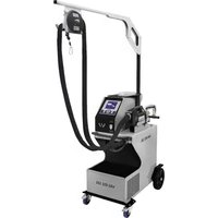
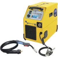
The AUTOPULSE is a «synergic» semi-automatic welding machine, ventilated for welding (MIG or MAG). This machine is recommended for welding steel, stainless steel, aluminium and the brazing. Its adjustment is quick and easy with its «synergic» mode.
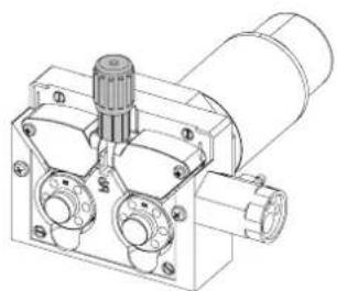
DESCRIPTION OF THE EQUIPMENT (I)
1-Cable gland (mains cable) 10-USB connector
2- On/Off switch 11-MMI
3-Gas connector T1 12-Push Pull (PP) connector
4- Gas connector T2 13- Spool Gun (SP) connector
5-Gas connector T3 14-Texas connector (-)
6-Cylinders support 15-Euro connector T1
7- Reel supports 1, 2 et 3 16-Euro connector T2
8-Wire feeder motor 17-Euro connector T3
9- Switch for purge-gas and wire feeding
HUMAN-MACHINE INTERFACE (HMI)

HMI
Please read the Human Machine Interface (HMI) which forms part of the equipment's user literature.
POWER SWITCH
- The 400V model is supplied with a 16 A plug, type EN 60309-1, and should only be used in a three-phase 400V (50-60 Hz) four-wire electrical installation with a grounded neutral conductor.
The 208/240 V model is supplied without a plug and should only be used in a three-phase 200-240 V (50-60 Hz) four-wire electrical installation with a grounded neutral.
The effective absorbed current (1eff) is indicated on the equipment, for maximum operating conditions. Check that the power supply and its protection (fuse and/or circuit breaker) are compatible with the current required in use. In some countries, it may be necessary to change the plug to allow use at maximum conditions. - The 400V model is designed to operate on 400V + / - 15% electrical voltage. It will go into protection if the supply voltage is less than 330Vrms or greater than 490Vrms. (a fault code will appear on the keypad display).
The 208/240V model is designed to operate on 220V - 15% +20% . It will go into protection if the supply voltage is less than 185Vrms or greater than 270Vrms. (a fault code will appear on the keyboard display). - It is switched on by turning the on/off switch (2 - FIG 1) to position I, and off by turning it to position O. Warning! Never switch off the power supply when the machine is under load.
CONNECTING TO A POWER SOURCE
The machine can work with generators as long as the auxiliary power matches these requirements:
- For the 400V model: The voltage shall be alternating, its RMS value shall be 400V + / - 15% , and its peak voltage shall be less than 700V .
- For the 208/240 V model: The voltage shall be alternating, its RMS value shall be 220V - 15% +20% , and its peak voltage shall be less than 375V.
- The frequency must be between 50 and 60Hz
It is imperative to check these requirements as several generators generate high voltage peaks that can damage these machines.
USING EXTENSION LEADS
All extension leads must be of a suitable length and width that is appropriate to the equipment's voltage. Use an extension lead that complies with national safety regulations.
| Current input Extension | sion lead section (<45m) |
| 400 V | 2.5 mm² |
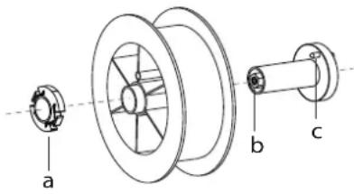
SETTING UP THE REEL

- Remove the nozzle (a) and contact tube (b) from your MIG/MAG torch.
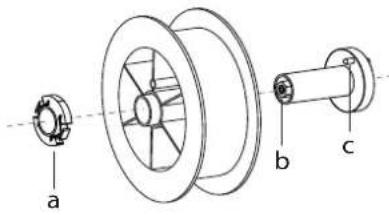
Open the power source's hatch.
- Position the reel on its holder.
- Take into consideration the reel stands's drive lug (c). To fit a 200mm reel, tighten the plastic reel holder (a) to the maximum.
- Adjust the brake wheel (b) to prevent the non-moving spool from tangling the wire when the welding stops. In general, do not overtighten, as this will cause the motor to overheat.
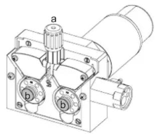
LOADING THE FILLER WIRE
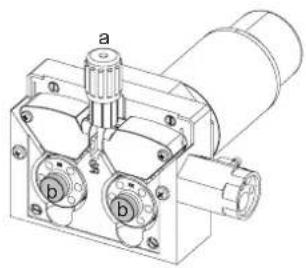
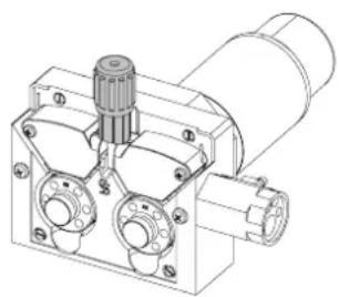
To change the rollers, do the following:
- Loosen the knobs (a) to the maximum and lower them.
- Unlock the rollers by loosening the retaining screws (b).
- Insert the correct motor rollers for your application and tighten the retaining screws.
The rollers supplied are double groove rollers: - alu 0.1/0.2 (T1 + T3)
-steel0.8/1.0(T3)
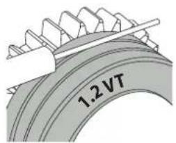
- Check the inscription on the roller to ensure that the rollers are suitable for the wire diameter and the wire material (for a 1.2 wire, use the 1.2 groove).
- Use V-grooved rollers for steel and other hard wires.
- Use U-grooved rollers for aluminium and other soft, alloyed wires.

: visible inscription on the roller (example: 1.2 VT)
→:groove to use
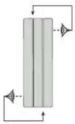
Do the following to install the filler wire:
- Loosen the dials to the maximum and lower them.
- Insert the wire, then close the motor reel and tighten the dials as shown.
- Operate the motor using the torch trigger or the manual wire feed button (I-9).

Notes:
- Too narrow a sheath can lead to unreeling issues and can lead to the overheating of the motor.
- The torch connection must also be properly tightened to prevent it from overheating.
- Ensure that neither the wire, nor the reel, touches the device's mechanism, otherwise there is a danger of short-circuiting the machine.
RISK OF INJURY FROM MOVING COMPONENTS

The reels have moving parts that can trap hands, hair, clothing or tools causing injuries!
- Do not touch rotating, moving or driving parts of the machine!
- Ensure that the housing covers or protective covers remain fully closed when in operation!
- Do not wear gloves when threading the filler wire or changing the filler wire reel.
SEMI-AUTOMATIC STEEL/STAINLESS STEEL WELDING (MAG MODE)
AUTOPULSE can weld steel wire from 0.6 to 1.2mm and stainless steel from 0.8 to 1.2mm (II-A).
Welding steel requires a specific gas (Ar+CO2). The proportion of CO2 may vary depending on the gas used. For stainless steel, use a mixture with 2% CO2. When welding with pure CO2, it is necessary to connect a gas preheating device to the gas cylinder. For specific gas requirements, please enquire with your gas distributor. The gas flow rate for steel is between 8 and 15 litres / minute depending on the environment. Synergies in Pulse mode are optimized for a gas flow between 12 and 15 liters / minute. To measure the gas flow at the flare outlet, you can use the optional flowmeter (ref. 053939).
SEMI-AUTOMATIC ALUMINIUM WELDING (MIG MODE)
AUTOPULSE can weld aluminium wire from 0.8 to 1.2mm (II-B).
Aluminium use requires a specific pure argon gas (Ar). For specific gas requirements, please enquire with your gas distributor. The aluminium gas flow rate is between 15 and 20 l/min depending on the environment and the welder's experience. Synergies in Pulse mode are optimized for a gas flow between 12 and 15 liters / minute.
The differences between using the unit on steel or aluminum are:
- Use specific drive rolls for aluminium welding.
- Apply minimum pressure on the pressure rollers of the motor-driven reel to avoid crushing the wire.
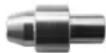
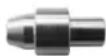
- Use the capillary tube (designed to guide the wire between the drive rolls in the motor and the EURO connector) only for steel/stainless steel welding (II-B).
- Use a torch designed for aluminium. This aluminium torch is fitted with a teflon torch liner in order to reduce frictions. DO NOT cut the liner at the edge of the fitting! This liner guides the wire from the drive rolls.
- Contact tube: use a SPECIAL aluminium contact tube corresponding to the diameter of the wire.
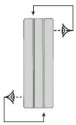
When using red or blue sheathing (aluminium welding), it is recommended to use the 90950 (II-C) accessory. This stainless steel sheath guide improves the centering of the sheath and facilitates the flow of the wire.

Video
SEMI-AUTOMATIC WELDING IN CUSI AND CUAL (SOLDERING MODE)
The machine can weld CuSi and CuAl wire from 0.8 to 1.2mm
In the same way as with steel, a capillary tube must be set up and a torch with a steel sheath must be used. When braze welding, pure argon (Ar) should be used.
GAS SUPPLY
- Fit a suitable pressure regulator to the gas cylinder. Connect it to the welding station with the pipe supplied. Attach the two hose clamps to prevent leaks.
- Ensure that the gas cylinder is held securely in place with a chain attached to the power source.
- Set the gas flow rate by adjusting the dial on the pressure regulator.
NB: To adjust the gas flow rate more easily, use the rollers on the motorised spool by pulling the trigger on the torch (loosen the brake wheel on the motorised reel so that no wire is drawn in). Maximum gas pressure: 0.5 MPa (5 bar).
This procedure does not apply to welding in «No Gas» mode.
RECOMMENDED COMBINATIONS
| (mm) | Current (A) Ø Wire (mm) Ø Nozzle (mm) Flow rate | L/min | ||
| MIG | 0.8-2 20-100 0 | 8 12 10-12 | ||
| 2-4 100-200 1 | .0 12-15 12-15 | |||
| 4-8 200-300 1 | .0/1.2 15-16 15-18 | |||
| 8-15 | 300-500 1.2/1.6 | 16 18-25 | ||
| MAG | 0.6-1.5 | 15-80 | 0.6 | 12 |
| 1.5-3 80-150 0 | 8 12-15 10-12 | |||
| 3-8 150-300 1 | .0/1.2 15-16 12-15 | |||
| 8-20 | 300-500 1.2/1.6 | 16 15-18 |
MIG/MAG(GMAW/FCAW)WELDING MODE
| Welding processes | ||||||
| Settings | ADJUSTABLE SETTINGS | MANUAL | STD DYNAMIC | PULSE | COLD PULSE | |
| Couple material/gas | - Fe Ar 25% CO2- ... | - | ✓ | ✓ | ✓ | Choice of the material to be welded.Pre-installed welding user settings |
| Wire diameter | Ø 0.6 > Ø 1.2 mm | - | ✓ | ✓ | ✓ | Choice of wire diameter |
| ModulArc | OFF - ON | - | - | ✓ | ✓ | Activating or deactivating the welding current's modulation (Double Pulse) |
| USING THE TRIG-GER | 2T, 4T | ✓ | ✓ | ✓ | ✓ | Choice of trigger welding management mode. |
| Spot welding mode | SPOT, DELAY | ✓ | ✓ | - | - | Selecting spot welding mode |
| First Setting | Thickness Start-up Speed | - | ✓ | ✓ | ✓ | Choosing the main setting to be displayed (thickness of the workpiece, average welding current or wire speed). |
| Power | Hold Thermal coefficient | ✓ | ✓ | ✓ | ✓ | See «Power» section on the following pages. |
Access to some welding settings depends on the selected display mode: Settings/Display mode: Easy, Expert, Advanced. Refer to the HMI manual.
WELDING PROCESSES
For more information on GYS pre-installed user settings and welding processes, scan the QR code:

SPOT WELDING MODE
- SPOT WELDING
This welding mode allows the pre-assembly of parts before welding. Spot welding can be done manually using the trigger or timed with a predefined spot welding period. This spot welding makes reproduction and execution of non-oxidised weld points easier (accessible in the advanced menu).
- TIME LIMITS
This is a welding mode similar to SPOT welding but with predefined weld and dwell times, as long as the trigger is held down.
CONFIGURING THE SETTINGS
Units
| Wire speed | m/min | Amount of filler metal deposited and consequently the welding intensity and penetration. |
| Voltage V Control over the cord's | width. | |
| Self - Lessens the welding current | more or less. To be set according to the welding position. | |
| Pre-Gas s When the torch is bled | and the gas shield is created before ignition. | |
| Post-Gas | s | Duration of the gas protection after the arc is extinguished. It protects the workpiece and the electrode from oxidation. |
| Thickness | mm | The pre-installed user settings (synergies) allow for a fully-automatic set-up. Working with different thicknesses automatically sets the appropriate thread tension and speed. |
| Start-up | A | The welding current is set according to the type of wire used and the material to be welded. |
| Arc length | - | Used to adjust the distance between the end of the wire and the weld pool (tension adjustment). |
| Approach speed | % | Progressive yarn speed. Before priming, the wire moves slowly to create the first contact without jolting. |
| Hot Start | % & s | The Hot Start is an overcurrent used at the start that prevents the wire from sticking to the workpiece. The intensity (% of welding current) and the time (seconds) can be programmed. |
| Crater Filler | % | This idling bearing current is a phase after the current is lowered. The intensity (% of welding current) and the time (seconds) can be programmed. |
| Soft Start | s | Gradual current increase. The current is controlled between the first contact and the welding process in order to avoid the possibility of violent ignitions or jolts. |
| Uplipse | s Upslope current | |
| Cold current | % | Second welding current known as a «cold» welding current. |
| Pulse frequency | Hz | Pulse frequency |
| Duty cycle | % | In pulsed mode, the hot current time is adjusted in relation to the cold current time. |
| Downslope | s Downslope current. | |
| Tack welding | s Set duration. | |
| Time between two points | s | Time between the end of a point (excluding Post-Gas) and the start of a new point (including Pre-Gas). |
| Burnback | s | Feature preventing the thread sticking to the bead. This is timed to coincide with the wire rising from the weld pool. |
Access to some welding settings depends on the welding process (Manual, Standard, etc.) and the selected display mode (Easy, Expert or Advanced). Refer to the HMI manual.
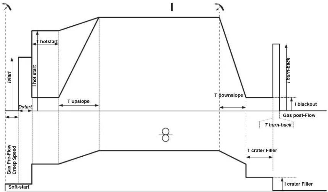
MIG/MAG WELDING CYCLES
Standard 2T process:
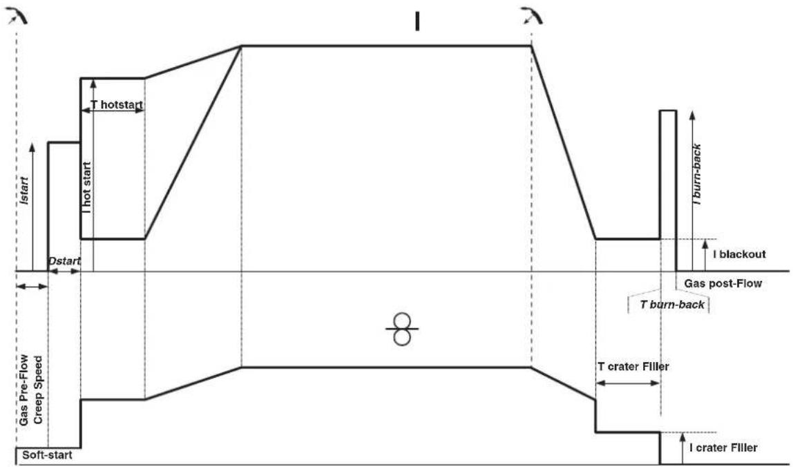
When the trigger is pulled, the pre-gas starts. When the wire touches the workpiece, a pulse initiates the arc and the welding cycle starts. When the trigger is released, the wire feeding stops and a current pulse cleanly cuts the wire, followed by the post-gas. As long as the post-gas has not finished, pressing the trigger will allow a quick restart of the weld (manual chain stitch) without going through the HotStart phase. A HotStart and/or a crater filler can be added to the cycle.
Standard 4T process:
In a standard 4T process, the timing of pre-gas and post-gas is managed automatically. HotStart and crater filler are both controlled by the trigger.
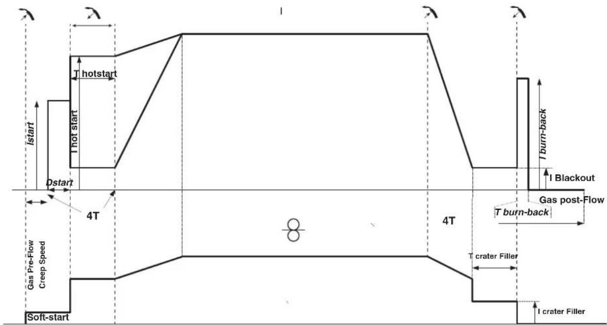
Pulsed 2T process:
When the trigger is pulled, the pre-gas starts. When the wire touches the workpiece, a pulse initiates the arc. Then, the machine starts with HotStart or upslope and finally, the welding cycle starts. When the trigger is released, the downslope initiates until it reaches crater fill. Then the STOP PEAK cuts the wire followed by the Post gas. Just as in Standard mode, the user can quickly restart the welding process during the post-gas phase without going through the HotStart phase.
Pulsed 4T process:
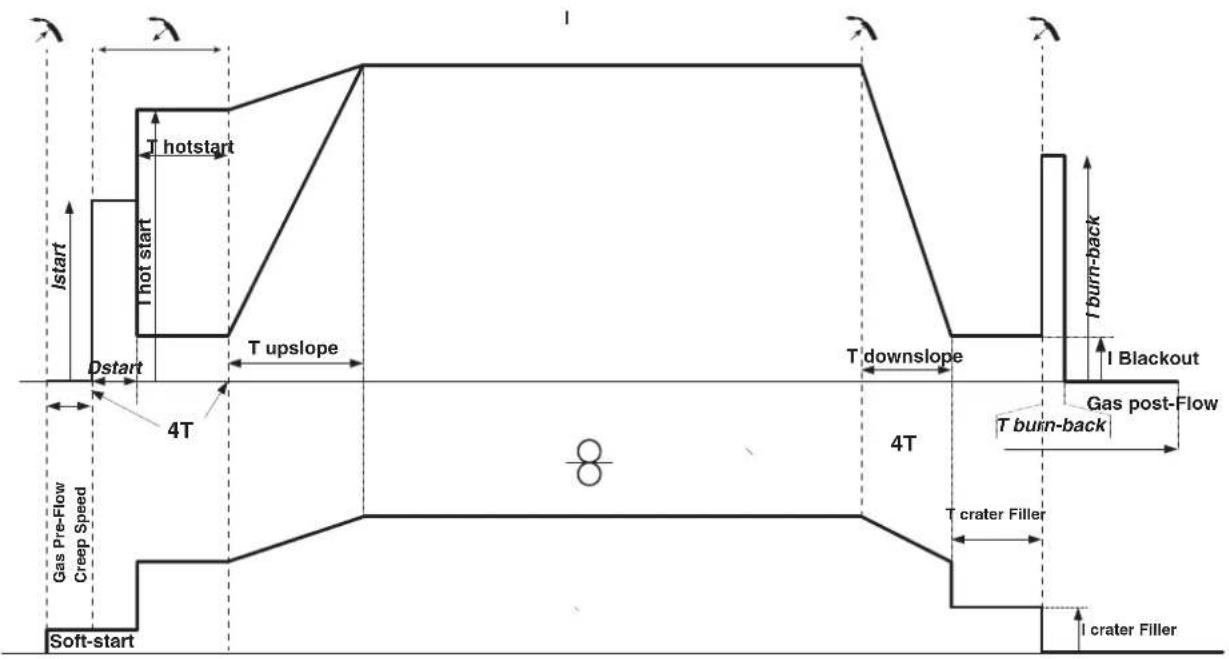
In pulsed 4T mode, the timing of the pre-gas and post-gas is managed automatically. HotStart and crater fill are controlled by the trigger.
POWER
A method developed for welding with DMOS-regulated energy control. As well as displaying the energy of the weld bead after welding, this mode allows the setting of the thermal coefficient according to the standard used: One for ASME standards and 0.6 (TIG) or 0.8 (MMA/MIG-MAG) for European standards. The energy displayed is calculated taking into account this coefficient.
OPTIONAL PUSH-PULL TORCH
| Reference number | Wire diameter Length | Cooling type | |
| 044111 0.6 > | 1.0 mm 4 m Air | ||
| 046283 0.6 > | 1.2 mm 4 m Air |
A push-pull torch can be connected to the power source via the socket (I-12). This type of torch allows the use of AlSi wire even in 0.8mm with a torch length of 8m . This torch can be used in all MIG-MAG welding modes.
The Push-Pull torch is detected by simply pulling the trigger.
When using a push-pull torch with potentiometer, the highest control range setting can be set using the interface.
The potentiometer can then range anywhere between 50% and 100% within this setting.
OPTIONAL SPOOL GUN TORCH
| Reference number | Wire diameter Length Cooing type | |
| 041486 0.6 > | 1.0 mm 4 m Air |
A Spool Gun torch can be connected to the power source via the socket (I-13). It can only be used in synergic, standard and manual mode.
-
In manual mode, only the wire speed adjustment button is remote on the torch (no adjustment possible on the machine interface).
-
In synergic mode, the adjustment button allows to act between 50% and 100% of the value set on the HMI.
The detection of the Push-Pull torch is done by simply pressing the trigger.
For more details, please read the instructions provided with the torch.
DEFECTS: CAUSES & SOLUTIONS
| SYMPTOMS POSSIBLE CAUSES SOLUTIONS | ||
| The flow of the welding wire is not constant. | Clogs blocking the opening. | Clean the contact tube or replace it with non-stick material. |
| The wire slips in the roller. Reapply the non-stick product. | ||
| One of the rollers is spinning. Check the tightness of the roller screw. | ||
| The torch cable is twisted. | The torch cable should be as straight as possible. | |
| The reel motor is not working. Reel brake or roller is too tight. Loosen the brake and rollers. | ||
| Incorrect wire unwinding. | Dirty or damaged wire guide. Clean or replace. | |
| Roller pin key is missing. Reposition the pin in its slot. | ||
| Reel brake is too tight. Loosen the brake. | ||
| No current or wrong welding current. | Improper connection of mains plug. | Check the plug connection and verify that the plug is connected to the power supply. |
| Poor earth connection. | Check the earthing cable (its connection and the condition of the clamp). | |
| No power. | Check the torch trigger. | |
| The wire jams after passing through the rollers. | Crushed wire guide sheath. | Check the sheath and torch. |
| Wire jamming in the torch. | Replace or clean. | |
| No capillary tube. | Check that the capillary tube is present. | |
| Wire speed too high. | Reduce the wire speed. | |
| The weld bead is porous. | The gas flow is insufficient. | Adjustment range from 15 to 20 L / min. Clean the base metal. |
| Gas cylinder empty. | Replace it. | |
| Unsatisfactory gas quality. | Replace it. | |
| Air circulation or wind influence. | Avoid draughts and protect the welding area. | |
| Gas nozzle is too clogged. | Clean or replace gas nozzle. | |
| Bad wire quality. | Use a wire suitable for MIG/MAG welding. | |
| Condition of the welding surface is too poor (rusted, etc.). | Clean the workpiece before welding. | |
| The gas is not connected. | Check that the gas is connected to the power source's inlet. | |
| Excessive sparks. | Arc voltage is too low or too high. See welding settings. | |
| Poor earth connection. | Check and position the earth clamp as close as possible to the area to be welded. | |
| Insufficient gas protection. Adjust the gas flow. | ||
| No gas coming from the torch. Poor gas connection. | Check the connections of gas inlets. | |
| Check that the solenoid valve is working. | ||
| Error while downloading. | The data on the USB stick is incorrect or corrupted. | Check your data. |
| Backup error. | You have exceeded the maximum number of backups. | You need to delete some programs. The number of backups is limited to 500. |
| Automatic deletion of JOBS. | Some of your JOBs have been deleted because they were incompatible with the new pre-installed user settings (synergies). | - |
| Push Pull torch detection error. - Check Push Pull torch connection. | ||
| USB key error. | There is no JOB detected on the USB stick. - | |
| The product's memory space is full. Free up some space on the USB key. | ||
| File error. | The file does not match the pre-installed user settings (synergies) downloaded to the product. | The file was created with pre-installed user settings (synergies) that are not present on the machine. |
WARRANTY CONDITIONS
The warranty covers any defects or manufacturing faults for two years from the date of purchase (parts and labour).
The warranty does not cover:
- Any other damage caused by transportation.
- General wear of parts (eg.: cables, clamps, etc.).
- Damage caused by misuse (incorrect power supply, the dropping or dismantling of equipment).
Environmental failures (pollution, rust and dust).
In the event of a breakdown, return the appliance to your distributor, together with:
- dated proof of purchase (receipt, invoice, etc.),
- a note explaining the breakdown..
IpeDynpEnTe OkpykaHouix He CMOTpeTb Ha dny I o6paBaTaBbAembIe DeTaN HnHaDeBaTb 3aunTHyo paOchUOJeKdy.

Hocnte HayuHnKn npoTnB uMa, ecn cbapOchb npocecc doCTnraet 3ByKOBOrO ypOBH BAWe Do3BOIeHHOrO (To Je OTHOCITc K0 BCem IInzam, HaxoJauuMmC B 3OHe CBAPKn).
Depknte pykn, BONocbl, Odekny noaJIbwe ot noDbNkhbIX uactei (BnIraTeIb, BeHTnIyTOp...).
HnKOrda He ChnMaIte 3aunThbI KOpNyc C CnCTeMbI OxnaXdEHHa, KOra nctOuHN KIOHn HnnpxKeHHm. PpOn3BODHTeH He Hecet OTBeTcBEHHO B Cnyae HeCuaCTHO CnyaJ.
ToIbKO YTO CBapeHHbIe DeTaNIN ROPaYH MOrYT Bbl3BaTb OxOri PnI KOHTAKTe C HIMM. Bo BpMa TExo6cnyKbAHNr rOpEKN IIN 3JIeKTPOdoepKaTeJy y6eInTECb, YTO OHN DoCTaTOHO OxNaDInCb NIOOxDNITE KAK MMHNYM 10 MNHT nepeH naON paBcT. PnI nCnOB3OBAHUN rOpEIKN C KUnkOCTbIM OxNaXDeHem CNTema OxNaXDeHn DOnJXHa 6bIT bKNIIOUHe, YTObI He O6KeYbCS KJNDKoCTbIO.
Oueh Baxho o63oanTb pa6oyu 30hy nepei TeM, kak ee nokHyt, yTo6bl 3aunTntb IIOeH N MUYIecTBO.
CBAPOHbIE DbIM IΓA3

BbIeIeIeMbIe npn CBapKe DbIM, ra3 n nbIb onaChb I dIy 3doOpBb. BeHTnIaIg DoJNkHa 6bIb DoCTaOHyH, m MoKet notpe6oBaTc DOONHITeNbHa NoaHa BO3dyXa. Pn HeIOCTaTOUHO BHTnIaIg MOxHO BocNoIb3OBA Tc MaKoI CBAPuNka-peCnpaTopom.
PpOBepTe, YTO6bI BCaCbIBaHHe BO3dyXa 6blIO 3ΦΦeKTHBbIM B COOTBeTCTBn C HOpMaMn 6e3OnacHOCTn.
Bbte BnMaTeIbHb: CBapKa B He6oJIbXnx NOMEeEHNx Tpe6yEt Ha6bnOeHna Ha 6e3OnaChom pacCToHnn. Kpome Toro, Cbapka HekOTopbIX MeTannOB, CoepKaaXnx CBnHeu, KaDMn, cHk, pTyTB n nn daXe 6epnIInm, MoKet 6bIt bYpe3BbUaHnBOpeHno. CneJyET OHNCTITb OT Xnpa DetanPi nepeD cbapko.
Ta30BbIe BaIIIOHbI DoJIKNbI XpaHITbcB OTKpbItbIX ININ XopoOo npoBeTpnaEBaEMbIX NOMEueHnX. OHn DoJNkbI 6bITb B BepTnKaJIbHOM NOIOKeHN I 3aKpeIeHbHa cToIke INI TeneXke.
Hn B Koem cIyuae He Bapntb 6Jnn3n Jknpa nn Kpackn.
PNCIOKAPA INB3PbIBA

NoHocTbO 3aunntte 30Hy CBapKn. Bo3ropaembl MaTePnAbl DoNkHb6bTy ydaenHb KaMHNMym Ha 11 MetpoB. PpnoBnOIOKapHoe o6opynobAHne DoNkHO HaxoOnTBcB6n3n npObeHn CBapOhyx pa60t.
OcToPoxKHO C 6bpyI3rAmn ropAryero MaTeepnana nnN nckp. OH MoYr NOBNeB 3a co6oN noXap nnN B3pbV D aKe chepe3 uen.
YdaHnTe IIOeN, Bo3ropaembIe NpeMTeB IN Bce EMKoCTn NOd DaBHeHEm Ha 6e3OnacHoe paccToHHe.
Hn B KOem cnyae He BaPte B KOHTeHepax nnn 3akpbItbIX Tpy6ax. B cnyae, ecn OHn OTkpbl, To nepeD cbapKOn Hx HxHo OCBOOaNTb OT BCEx
B3pbIBaTbIX NIN BO3RopaembIX BeueCTB (MacNO, TOnJIINBO, OCTaTOUHbIe ra3bl ...).
Bo Bpem onepaunu nnnoobnna He hnapabnTe nHCTpymEnB CTOpOHy nCToUHnKa CBapOHOro ToKa IIN BO3rpaembIX MaTePnaNoB.
T3OBBIEBAJIIOHBI

Tg30M, BbIXoJHIM N3 ra3ObBix 6aIIOHOB, MoXHO 3aDOxHybC B Cnyae erO KOHcHTpaunn B nOmeueHN CBapKn (Xopoio npOBeTrpuaite).
TpaHcnpTnpoBka DoJNkHa 6bTB BbIbIeHHe 6e3oNaChO: UINHApbl 3aKpbItb, a NCTOCHK CBAPOHOr TOKa BbIKIOueH. BaIIHO bdoJHKb6bTB BepTKaJIbHOM IonoKeHN I 3aKpeJIeHbI Ha NoCTaBKe, YTObI OpraHHTb Pnck NaDeHnA.
3aKpbBaiTe 6aIIOH B nepepbIbe MeJy DByMg IcNoJIb3OBAHnM. ByIbTe BHNMaTeJIbHbI K N3MeHeHIO TeMnepaTpybI nIpe6bIBaHIO Ha cONHc. BaIIOH He dOnKeH cOpNkacatbcra C pIameHem, 3JeKTpueckoD yToR, rOpEko, 3aXIMOM Maccbl nC JIObIM dpYIM nCTOUYKOM Tepna nn CBeueHn.
Depknte er noanbwe ot 3neKtpueecknx n CBapouhbx cenei n, cneObaTeNbHO, HNKoIa He BapTe 6aannOH ndoabneHem.
BbIe BnHMaTeBnHbI: npn OTKpbTmN BeHTnla 6aIIHOHa y6epnte roIOy o THrnoy H6eNTecb, qTO nCNoIb3yeMbl ra3 COOTBeTcTBey MeToDy CBapKn.
JIKTPNUECKA B3OONACHOCTb

IcnoB3ayemar 3JKeTpuceckara cetb doJxHa o6a3aTeNbHO 6bITb 3aEmneHHo. Co6nOdaTe kaH6p npedoxpaHnteYkzaahhhha annapate.
3NeKtpueckn pa3pnd MOKeT Bbl3BaTb npMbIe NIN KOCBeHHbIe paHeHry, I DaXe CMeptb.
HkoIa He doTpaBaiTeb Do uacteI noI HanpRKeHHeM KaK BHyTpN, TaK n ChapyKn NCTOuyHnka, KOrIa OH nOd HapPaeHnEM (ropeKN, 3axMbI, ka6en, 3neKTpobl), T.K. OHI NOIKIOUeHbI K CBAPoHNo ceHn.
IpeTeM, KaK OTkpItb NcToHnK, eO HyXHO OTKnIOuHTb OT cETN IIOJOKDaTb 2 MInHyTb IINr TORO, YTO6bI BCE KOHNDeHCaTOPb pa3pRdNtncB.
HnKOrda He DoTpaHbAaTeCb OndHOBpeMeHHo Do ropeKNn Nn 3JeKToPOOepKaTeJn I Do 3axMa Maccbl.
Ecn KabeHn, ropEnK nOBpeXeHbI, nonpocnte KbaInnncnpoBaHHbIX u ynoHMOeHHbIX cneuaJIncTOB IN 3aMeHHTb. Pa3Mepbl cehenna KaBeen dOgKhbl COOTBcTBOBaTb npimeHenIO. Bcerda Hocnte cyxyo odexdy B xopoWem coCToAHIN DnA I3OJUuN OT CBAPOHIO UEN. Hocnte I30npyioyoo6byb Hezabncmo OTo Tcpebl, rde bbl pa6oTaTe.
KJIACCHNΦHKAUNI 3JEKTPOMAHHTHO COBMECTMOCTN (BEPCN400B)

3TO 60pOyOBAHnKlACCA A He NoDxOoNT DnI NcNoBtOBAHnB B KInbIX KBaPTanax, rIe 3NeKTPuYeckn TOK noJaetc
6ObseCTBeHHOn CnCTEmoN nHTAHn Hn3KOrO HanpJKeHnB. B TaKnx KBaPTanax MOrY TB O3HNKHyTb TpyHOCTn ObecneueHn
3JIeKTPoMaTHHrTHyIO COBMeCTMOCbT h3-3a KOHdyKTNBbIx INHdyKTHBbIX NOMex Ha paAnOacToTe.
3ToT annapaT COOTBETCTBYET HopMe CEI 61000-3-12.
Pn ycnoBn, YTO cnpotNBHeHne HN3KOBnTHoC eTn O6eero NHTaHnB B o6e Toke CoedHHeH Mehwe Zmax = 0.349 om, 3TO o6OpyOBaHne COOTBeCTByET IEC 61000-3-11 n MoKet 6bIb NOKnOHeo K HN3KOBnTBHbIM CTeAM O6eero NtTaHnA. CneuaNNCT, yCTaHOBwHnn annapat, INI NoJIb3OBaTeNb, DOnJHbI y6eINbC8, O6paTnBwHncb Pn HaIObHOCTN K opraHn3aun, OTBeauOe 3a EKnpyatauio CnCTeMb IITaHnB, B TOM, YTO ee NnHOe cnpotNBHeHne COOTBeCTByET npedeJaM NOnHoro conpoTNBHeHn.
MAGHHTBIEIOJIa
3NeKtpnueckn TOK, npoxoJauu chpe3 IIO60 npOoHb Kbl3bBaet NkAn3OBaHHbe 3NeKtpomarHHTbIe nna (EMF). CbaOpHbTOK Bbl3bBAET 3NeKTPomarHHTHOE NOE BOKpyc CBapOHOU cENN CBAPOHOrO o6opydoHAHn.
3neKtpomarHHTbIe nOJ EMF Moryt co3daTb NOMEXI INE HeKOTopbIX MeiunHckNX IMnlaHTaTOB, HApPIMep 3neKtpokapDIOCTMnyIaTOpOB. Mepbl 6e3oNaChocTN DoNkHbI 6bITb npInHbTI dIg IIOdeI, HOcAUX X MeiunHckXe IMnlaHTaTbI. HanpIMep: orpaHueHne DocTyna dIpynpoxKnx, INI OeHKa ININBvduyabHBO rCKa IJI CBAPsKa.
Bce cbapuikn doJKNbI nCIOJIb3OBaTb CneDyUOUIne npOeDpybI DnA MHHMm3aUN B03DeiCTBnA 3JEKTPOMaTHNbIX NOJe:
paonnooxnCTcBapouhIe Kaebm BmecTe - no BO3MOXHOCTN 3aKpeHNTe INC NOMOuBIO 3aKIMa;
-ДерхИТecь кak MOЖHOДаЛБшо OT CBAPОHOn ZEN
HnB Koem cnyae He o6opauBaIte BOKpyc 6e6a CBapOuHbke Ka6eJI.
He pa3MeuaTe KOpNc MeXdy CbapOuHbIM Na6eIaMn. DepeKte oBa CbapOuHbIX Ka6eIa Ha OJHO CTopoHc KopNyca;
- PoiocoeunHte o6paTHbI Ka6eJIb K 3aROTOBKe KaK MoXHO 6nIXe K CBAPuBaEMOMy yAcTky;
He paobotaTe pAnOM, He caNTecb Hn PnpCNOHnTEcB K nCTOuHky CBapOuHoro TOka;
He CBapNBaTb npu TpaHCnOpTnpOBKe nCTOChNka CBapOCHoro TOKa NIn yCTpOJIcTBa NOdaU npOBOLOKN.

Iiua, nCnoB3yUoHne 3JekTpokapDnocTmMyJrTopbI, DOnKhbl npOKOHcyNbTnpOBaTbcR y Bpau nepeD pa6ToC daHHbIM o6opuyoBaHnem.
Bo3eCTBnE 3NektpomarHHTHO NOI B IpoceCE CBAPKIMoKET IMeTB NdpyRNe, eue He n3BeCTHbIe HayKe, nocIeCTBnI
IJI 3IOPOBbI.
PEKOMEHDAUINIJI OUEHKN 3OHbICBAPKN CBAPOHON YCTAHOBKN
06nne CBeHn
Ponb30BATENB OTBeaet 3a yctahOBky nncnObl30BaHne ycTaHO npHOn dyroBOCBAPKn, cneyra yka3AHmnpo3BOHTEN. PnO6hApyeHHnJIeKTPOMaHTHBIX M3nyehn NpIb30BATENB annapata pyHOn dyROB CBAPKn DOJNKeH paoBn IPO6NEMY C NOMOuBIO TexNHueCKO NOpeKNNPON3BOHTEN.B HEKOToBPx CnyAax 3TO KOPpeTKpyIOUee DeICTBNE MOKET 6bITb DOCTaTOHO IpocTbIM, HAnpIMep 3a3EmHeHE CBAPoHOI CEPII B DpyrNX CNYAAX BO3MOXHO NoTpe6yETcC O3dAHN He 3NeKTPOMaHTHoro 3kpaHa BOKpy INCTOHNKA CBAPoHOrTO KA u BCsE CBAPuBAemDeTANI NYTeM MoTHpOBOHn BXODHBx FInbTPOB.B IIO6OM CNYAae 3NeKTPOMaHTHtBE IN3nyehn DOJXHbI 6bITb YMeHbSeHbI TAK, YTO6BI OH6Bol7e He CO3DaBANI NOMex.
OueHka CBapoHoi 3Onbl
Ipeep yctahOBKO oobopyoBaHnry dYROB CBAPKn noJIb30BaTeJIb DOJIKeH OueHNT bO3MOXHbIe 3NeKTpOMaHHTHbIe np6neMb, KOtOpblc MOrTy BO3HNKHyT b OKpyKaIOUe cpeJe. YTO DoJNXHO 6bITb yUTeHo:
(a) HAIHnue HAD, IODI pRdOM C O6OpOBAHnEM DnIyROBcBapKn dpynx CnIOBbIX, YnpaBnIooX, CNHaNbHbIX N TepeOHbIX Ka6eJIe; 6)PpneMHnKn npepaTChnKa paINO n TeneBnDEHn.
(B) KOMNbIOTepbI IN dpyroe KOHTpOJIbHoe o6OpydoBaHne;
r) obopydoBaHne, IMeOoee pewaOooee 3NaueHne dIy 6eOanacHOCTn, HApIMep 3aunTa npOMbIIeHHoro o6OpdyoBaHnra;
13OpOBBe HIODei, KOToPbIe HaxoJrTcH No6JIIO3OCTn HAnpIMep, pN IcNoJIb3OBAHmN KApDIOcTmYJrTOPOB INN CNYXOBbIX annpaTOB;
(e) 060pyoBaHHe, nCnONb3yeMoE dIg KaJIINb6pOBKn IIN NImMpeHnA
(K)HEBOCINPMMHNBOCTbDpyrOoobopydOBaHnKOKpyKaIOuei CpeJe.
IoiJIb3OBeaTeIb DoJIxHcY6eIITbcraB TOM, YTO BCE aIIapatbI B NOMEueHIN COBMeCTUMbl dpyr c dpyrom. 3To MOXET NOIHTpe6oBaT bONJHInTeIbHbIX 3aUHTbIX Mep;
(Ⅲ)BpemCyTOK, KOrdaIOnJXHbI pOBoDnTbcra CBapOuHbIe IINIpyrme pa60TbI.
Pa3MepbI paccMatpmbaem030hblcBapKn 3abncrt OT ctpkTybpI 3daHnN I pynnx pa6oT, KOtOpbI B HEM npoBoaTcR. PacmtpnbAemaar 30Ha MoKeT npocTpapa3a npedeJIbI pa3MeueHnY yTaHOBKn.
OueHka cbapouHoh yctaHOBKn
POMMIMO OueHKN 30HbI, OueHKa annapaTOB pyHOn dyROBO CBAPKn MOKeT NOMOy ONpeDeNTb N peWHTcNyan 3neKtpomarHnTHbIX NOMEX. OueHKa H3nyeHn IOnKHa yHTbBaTb H3MepeHn B ycNoBnx 3KcnNyatauun, KaK 3To yKa3aHO B CtaTbe 10 CISPR 11:2009. 3MepeHn B ycNoBnx 3KcnNyatauun MOrTy TAKKe NO3BOHnT b NOITBePntb 3ΦΦeKTHBHOCTb Me pNo CMrYeHIO BO3dEChTBnA.
PEKOMEHDAUINIPO METODNIKE CHNXEHHN3JIeKTPOMAHHTHOI N3JnyEHn
a.ObseCTBeHHa CeTb Ch6KeHn: ObopyoBaHHe dny DyROBcBapKn DoJNHO bItb NodKIOUeHO K O6IeCTBeHHOMy 3NeKTPocHa6KeHnIO B COOTBETBm C peKomeHdaunrMn PpO3BOIDTeR. B cNYae BO3HNKHOBEHn NOMex BO3MOXHO 6yEt Heo6xOdIMo pInHrTa IOnOJIHTeINbHbIe PpeDyPpeITbHbIe MepIs, Taek KAc FInltpauiu O6IeCTBeHHOH CImCTeMbl NITAHN. Bo3MOXHO 3auNTb 1wyp nITAHnAnnapaTa C NOMouh0 3kpaH3npyuOe OnnETrk, NIO So NOxOHMn PpCnOC6NeHem (B cNYae eCN AnnpaT pyHoi DYROB CBAPKn NocToHNO HaxOHTcRa Ha ONPeDEHNO paOboMeTe. Heo6xOIMO o6ecneHtB 3NEKTPnuCeKyo HnpepeBbHOctb 3kpaH3npyuOe OnnETrk No Bce DNnHE. Heo6xOIMO noODcoEHNHb 3kpaH3npyuOuyo ONnETrk K NTouHNIc CBAPoHORo TOKa dNRe OecneueHn XopoWero 3NeKTPnuCeKOro KOHTa MeXdy WHPom I Kopyncom hctOHHa CBAPoHORo TOka.
6. Texnueckoe 06cnyxnbHne 06pOyobAHnI ydyroBo CBAPK: O6opyoBaHne IJy dyroBOCBAPK DoJXHO npoxoNtbperynnpHoeTexnueckoe 06cnykmbAHne B COOTBETCTBN C pekOMehaunm NPO3BODHTENr. Heo6xoDMIO, Yo6bl BCE DOCTYbI, IIOK IN OTKnDbBAUOpceCAhT KOPNyca 6bln 3akpytbl n npabInbHO 3akpenHebl, KO4a annapaT pyHOn DYROBO CBAPK rTOB K pa6ote HaxoNTCB B pa6oemcoTOnHn. Heo6xOIMO, YTObl annapaT pyHOn DYROBO CBAPK He 6bl npeEpanah KaKIM 6bl TO HN 6bl NO opa3OM, 3a NCKIOuOHeHem HAcTpoE, yka3AHbX B PkyOBODCTBE pON3BOITENr. B qACTHOCTn, cJeTyEOTpReynipOBaT b NocnykbAtb NCKPOBO pOMeKytOK dYr n yctPoCTB nOdknra n CTaBnnaaun3aun Dyr B COOTBETCTBN C pekOMehaunm NPO3BODHTENr.
B.CBAPOHbIE KABEN CINOBIE Kaen : Kaen DoJHKbI 6bTb KaK MOXHO KOPOe N NOMeueHb Ipyr prdom C dpyrom B6n3N OT nOHa nnY.
r. 3KBNIOTeHuaJIbHOe coeHNHeHne: 3KBnIOTeHuaJIbHbIe coeHNHeHne: Heo6xoJIMO o6ecNeHTb coeHNHeHne Bcex MeTaNIIuecknx npedMeTOB OKpykaOuSei 30hI. TeM He MeHee, MetaJIINueckne npedMeTbI, coeHNHeHbIe Co CBapNBAeMoI detaIbU, yBeNJUHBAOT pNCK IINb3OBaTeJIy Udapa 3NEKTPuueckm TOkOM, ecNI OH OJHOBpeMeHHo KOCHeTcA TNX MeTAJIINuecknx npedMeTOB n 3NEKTPoJa. OepaTop DoJxhen 6blb NOnIpobAH OT TAKNX MetaJIINuecknx npedMeTOB.
d.3a3emnne 3arotobkn: 3a3emnne Cbapnaem DetanB B cnnyae, ecn Cbapnaemag DeTaN He 3a3emnne H No coo6paKeHHM 3JIeKTPnueeckOBe30AnachocntuN INBcNYCBOxP a3MepeOB u CBOero pacnoNoxeHnK, KaHnpimep, B cnyae Kopnyca cyHa NIN MetaIIOKOHCTpyknn npomblneHHORO Obekta, To cOeHNHeMe DeTAN C 3emNei, MoKET B HEKOToBbX CUYaXn HO He CNCTeMaTHueCKn, COpATNT bBb6pOcbI. Heo6xoJIMo 136Berat3a3emnne Detane, KOToPBte MOrNb 6bl yBEInuHT nDa IONb3ObaTeNe pNcK paHENH NIN Ke NOpeDnB dpyRne 3NEKTOpyctAHOBKn. Pn HAdo6HOCTn, cndyet Hapmyo NODcoeHNHtDe TAE MNE, HO B HEKOToBbX CTpaHax, KOTOpBE He paePbAOTn Pnmaoe NDOceHNHeH, ero HyKHO CdeNaTb C NOMouBIO NOxOJaUe KOHDeHCaTopa, BB6paHBO R 3ABNCIMOCn OT HAIOHOaBHO 3AKOHDATeBCTBA.
e. 3aunTa n 3kpaHnpoBaHHe: 3aunTa n 3kpaHn3npyUOaonlTeKa: BbIbOpOHaHa 3aunTa n 3kpaHn3npyUOaonlTeKa dpYrN K6beNe i O6bpyoBaHn, HaxOJaXxCB B 6n3JExaUeP a6OcE yAcTKe, NOMOeT orpaHnHTb np6IeMb, CBraHHbIe C nomexAmN. 3aunTa Bce CBapOHyOH 30Hb MoKET paccMaTPuBaTcB R HeKOToBix OC6bIx cnyAax.
TPAHCNOPTNPOBKA IN TPAH3NT NCTOCHNKA CBAPOHORO TOKAK

He nonb3yItecb ka6eIaMn nnr ropEnKo dnn nepeHoc a nToCHNka CBapOCHoro ToKa. Ero moXHO nepeHocHTb TOnbKO B BePTNKaJIbHOM nIOJKeHHN.
He nepeHocntb nCTouHnK Toka HaJ NIOdbMn NIN PpeMeTaMn.
HnKorTa He NoHNMaIte Ra3OBbI 6aIIIOH N IcTOOH KCBAPOHTo Ka OHOBpeMeHH. Xx TpaHCnOpTbHe HOPMb pa3NmuOTca. XeNaTeNbHO ChrTB 6oBuHy npoBOIOKn peep TeM, Ka KIOHMAtb IIIN PepeHOCITb IcTOOH KCBAPOHTo KA.
YCTAHOBKA ANIAPATA
-Поставыгосточик CBаочного TOKa Ha non, MaKсимаьнй Нан KaHNOH KOTOPORO 10°.
- PnpDcMoTnTe DoCTaTOH 6oJIbwoe npocTpaHCTBO nIg XopoWero npoBepuBaHn IctOCHNk CBapOHHOro ToKa nDocTyna KynpabNeHIO.
- He nCnoB3OBAb B cpe de coepkauei MeTaNnueckyU nbIb-NpBOoDnK.
- NCTOCHK CBAPOHORO TOKA DOJXKeH 6bITb ykpblOT npONNBHOrO DoXJa HcTOrHa coJIHue.
- 06opudobahne Imeet 3aunTy IP21,чTo 03naaet:
- 3aunty OT nonadHnB ONachIe 30hbl TBePdbIX TeI dNaMeTpom >12,5MMn,
-3aunTyOTBepTnKaJbHbIXKaneJIbBoDbl.

Bnykaohue CBAPOHyT a3eMnHOuNE npOBOa, NOpeHb o6OpDObAHne n3eKtpnueckne np6opbN BblBaHarpeBaHne KOMJIeKTKUOnx, YTO MOKeT npNBecTN K NoXapy.
-Bce cbapouhble coeHHeHHdoJKNbI KpENKO depKaTbcra. PPOBepaTe nx perynpaHNO!
- Y6eDnTeCb B Tom, UTo KpennHeNe DeTaN pOuHoe N 6e3 3neKtpnuecknx npo6nem!
- CoeINHtBe Bmte HIN NIOBcTe BCE 3nemEtbl CBapOCHoro nCToHnka, npoBOJrue 3nEKeTpUHeCTBO,Takne,KaK WACCn, TELeKKa IN NODbEMHbIe 3nemEtbl, YTO6bl I3OJIInpObaTb Hx!
- He Klaadne Ha CBapOHb I NCTOHHK, Ha TepeKky INI HA NOBemHbIe 3IeMeHTbI TAKHe np6Opbl, KaK dpEn, ToHJIbHbIe MaunHKn I T.D., ecIn OHn He n3OJInpoBaHb!
- Bcerda klaaTe cbapouhIe ropeKn IINI 3neKtpoOepKeTNe Hn IIOIpOBaHHyIO NOBepXHocTb, KOrDa Bbl Nc HcNtOJIb3yeTe!
Hyp nTahn ynnntenb n Cbapouhki Kaebj donxhbl nonhcTbpoa3MoTaHb BO n36kaHne neperpeBa.

Ipnoun3Bounten He Hecet OTBeTcBEHOCn OTHOCHTeINbHO yuepe6a,HaHeceHHoro Nuaam nnnpedMeTam, n3-3a HenpaBnBHorO nOnachoro nCnoNb3OBAHn 3TOrO o6OpydoBaHn.
OBCLNYKUBAHNE/PEKOMEHDAUIN


- TexHnueckoe 06cnyKbAHne DoJXHO pON3BOuNTbcra TOnbKO KBaINΦNpOBAHHbIM CNeUmaNCTOM. COBeyETc npOBoNDtbeExeroDHe TexO6cnyKbAHne.
-
OTKIIOHTe NITAHne, BByIdepHyB BNIKy H3 po3eTKn, IN NOIOKJNTe 2 MNHYtBi nepei Tem, KAK pNCTyTNb K TEXO6cnyKUBaHIO. BHyTpI annapata BbICOKne I onaChIe HanpRAKeHne I TOK.
-
Perynpho OtkpbBaIte annapat n npOyBaIte ero, yTo6bI ONUCTMb OT bIIIN. Heo6xOIMMo TAke XnpOBepaB BCE 3neKTPnuueckne CoeHHeNc c IOMOsbIO h01nIpOBaHHOrO INCTpyMeHTA. IpOBepKa DOJIKHA OCUyecTBaTc KBAJIINΦUINpOBaHHbIM CNEuaJIInCTOM.
Peynpno npobepre Te coToHne uHpy nTahn. Ecnu hyp nTahn noBpeKde, OH donKeH 6bIb 3aMeHeh npou3BOUnteEm, erc cepBncHO cnkybo nn KbaanfumpoabHHm cneuaanctom BO n36exaHne onaCHOt. - OctabnTe OTBepCTnI NCTOuHnKa CBapouHOro ToKa CBO6oHbIMN DnI IPOXoxJeHnB O3dyxa.
- He nCnoB3OBAb TaHnB annapat dna pa3Mop03Kn Tpy6, 3apAkn 6aTapei/AkKymIyIaTOPOB uIN 3anycka DnurateJe.
YCTAHOBKA IN PPNHUN DEIeCTBNA
ToIbKO onbITbHn ynoNHOOMOeHHb npOn3BODHTeNm CneuAnmCT MoKet OcyueCTBnTb YcTaHOBky. BoBpeM yctAHOBKn y6eHntecb, TTO nCTOHNK OKIOHcHOT cTeN. IocNeIOBaTeHbIe INI napAaIIeHbIe coeINHeHn IcTOHnKa 3anpeUeHbI. PeKOMeHNyETcNcNOJIb3oBaTb CBapOHTbe Ka6eHn INdyuHBe B KOMPiKeTE c AnnapaTOM dIra ONTImaIbHOH HAcTPOKN MaunHbI.
ONICAHNE
AUTOPULSE - 30 noynyabTomatueckn cnHepreTueckn cbapohb annapa c BHTnlauee nIg CBAPK (MNT nIN MAF). OH peKOMeHyIOCTc IINCBAPK CTAN, HEPKABeKN, anHomnna, a TAKKe dIg CBAPKn-NAKn. Bnaorapr «CNHePretueckomy» peXIMy annapat hactpanBaetc npocTo n 6blcTpo.
ONICAHNEOBOPYIOBAHNA (I)
1-Ka6eBbHbI BBOID (cTeBov Ka6eBb) 10-USB-pa3beM
2- PepeKIOUOaTeJIb BkIOUHeHr/ByIKIOUHeHr
3-Pa3bemT12-HaKIMHOoCoeHNHTenb(PP)
4- Ra3OBbI pa3bEM T2 13-Pa3bEM kaTyueHoro nCTOneta (SP)
5- Ra30BbI pa3bEm T3 14-Texacckn pa3bem (-)
6- Onopa unnnnnpa 15-Pa3bem Euro T1
7- Onopa katyuken 1, 2 n 3 16-Pa3bem Euro T2
8-KaTyuKa DvIraTeTn 17-Pa3bEm Euro T3
9-PeBepCnBnIperyIaTOpIaBHeHra3a,IoJaA npOBoJokn
11-HMI
HHTEPΦENC YEJIOBEK-MAUINHA (IHM)

HHTeppeic
Ioxayncta, 03nakombtec b c nHCTpyknei no 3Kcnnyatau nHTeppeca (HM), KOTOPaR ABnEeTcra aactbIO noNHOJ DOKyMeHaTaun Ha o6OpdyoBaHne.
ПИТAHNE-BKЛIOUYEHNE
·MoTeJIb 400B nocTaeTc C BnIKoN 16A, TnEN 60309-1, ndoJxHa nCIOJIb3OBA TbBCr ToIbKO B TpExpa3HO 400B (50-60Tc)
YeTbipexXPnpoBODHO3JeKTPoycTaHOBKe C 3a3eMJIeHHbIM HeItpaJIbHbIM PPOBODHNKOM.
·Modenb 208/240 B noctabnetaTcB 63 BnJIK n DOnkHa nCnObn3oBaTbcra TOnbKO B Tpexpa3Hoi YeTbipexnpoBOHOH 3NeKTpocetN 200-240 B (50-60 Tc) c 3a3eMneHHo HnEHTpaIbIO.
30000000000000000000000000000000000000000000000000000000000000000000000000000000000000000000000000000
·Modenb400B npedha3nepa5oBtbpnp3eKtpueckom HapxHm 400B+/-15%.Onpeeiet B pekm3aunTb,ecn hpanpkeHne nHTAHN6yET Mehwe 330 Brms nn6onbe 490 Brms.(Ha dncnnee KnaBnAtpyb noBnTC KO HecnPabHOCT).
- Modèle 208/240 Bnpénha3hauheha npaobto pnpn hapjkeHHN 220 B - 15% +20%. OH nepei dt b pexm 3aunTb, ecn n hapjkeHne nHTAHN 6ydt Mehwe 185 Brms nnn 60hwe 270 Brms. (Ha dncnnee knabnatpby noBnTc kO HeNCnPabHOCTn).
- OH BkIIOUaETc NOBOPOT M BbIKIOUaTeTg (2 - PNC. 1) B noIOKeHne I, a BbIKIOUaETc NOBOPOT M B noIOKeHne O. BnHMnHe! HnKOrda He OTKnIOuAte 3JeKTPoNITAHne, KOrDa MaUNHa HxOOnITc NoI Harpy3KoI.
NODKIIIOUeyHNE K 3JEKTPPOEHEPATOPY
AUTOPULSE moKet pa6oTaB c rHepaTOpAMn npu yCIOBm, YTO BCNOrOaTeJIbHaA MOUHOCTb COOTBeTCTByET CNeDyUOUM Tpe6oBaHnA:
-Дя moĐи 400В: habржспспдддддддддддддддддддддддддддддддддддддддддддддддддддддддддддддддддддддддддддддддддддддддддддддддддддд徳нгьадраитчhoe 3нayehne doлжсбьтб 400B+/-15%,а nkoBoe habржспспспспспспспспспспспспспспспспспспспспспспспспспспспспспспспспспспспспспспспспспспспспспспспспспспс.
700В,
-Длma moeHn 208/240 B:нарражену долхно 6bIbпермehнbIM, ergcpeHneKBaIpaTmHoe 3hauehene doLxho 6bIb 220B -15%+20%, a nkoBoe Hapraжену doLxho 6bIb MeHee 375 B,
- YacToTa DOnJXHa 6bItb B Dnna3OHe ot 50 Do 60 Fu.
Heo6xodmo npOBepntb 3TN ycNoBn, TAK KAK MHOrne reHepaTOpbl npOn3BoJrT cKaUKN BbICOKO HAnpJKeHN, KOtOpbl e MOryT NOBpeDHTb noCTaHcnn.
NcNoJIb3OBAHNE YdJIINHHTeJIa
YdHnHTeIN DOnKHBi NMeTb DInHy I CeueHne B COOTBeTCTBm C HAnpJxKeHnEM O6OpyIOBaHnI. IcNoJIb3yIte yDInHNTeN, OTBeHaOuN HopMaM BaSeI CTpaHbI.
| Нарожени на в王先生 | Сechени удиниителя (<45м) |
| 400В | 2.5mm2 |
YCTAHOBKA BOBHHbI
- OTKpoTKe KpbIuKy reHepaTopa.
-
YctaHOBnte 6o6nHy Ha epKaTeJIb.
-
O6paTne BHIMAHHe Ha npBODHOI WTHOCT (c) CTOKN MOTOBUNa. YTObI yCTAOHOBNTb KaTyWky DnAmETpOM 200 MM, MaKcImaJIbHO 3aTaNHTe PIIaCTIKOBBI JepKaTeJIb KaTyWkN (a).
-
OtperynpyTe TOpMO3 606HbI (b) TaK, YTO6bl npn ocTaHOBKe CBAPKn 6o6Hn no INhePmHe 3anyTalna npOBJOKy. He 3axHMaTe CInuKOM CInlbHo. 3To MOKeT pINBeCTN K nepepeBy Dniratela.
YCTAHOBKA PIPNCAIDOCHOH NPOBOJOKN
YTo6bI 3aMeHHTb POJIKN, BbINOJIHHTe CNeDyHOuJe DeIcTBnA:
- Ocna6bTe pyuKn (a) Do MaKcMMyMa n onyctnte nx.
-Pa36nokpyTepoNkU,ocna6bIKpepeXhBcBHTbI(b). - BCTaBbTe pOJIKN DVBraTeIe, NOxOJaIe IJRA BaIero npImeHEnr, n 3aTHeNTE KpeNXHbE BVHTbl.
IocTaNReMbIe pONIKN - 3TO CTaNbHbIe POJIKN C DBOHOn KaHaBKO:
- aIOM 0.1.2 (T1 + T3)
- cTanb 0.8/1.0 (T3)
-Поверпге Надимсь на рогик,чтобу yбeинъся,чTO OHI COOTBETCTBYOT ДИмETPy ПоволOKN n MaTePnAnI npOBONOK (ДЯnpОВONOK 01,2 ИСоюь3уte na3 01,2).
- IcnoIb3yIe poIKN c V-o6pa3HOJ KAHaBKOJ dRg CTAJIbHOJ npOBOJOKN n DpyrO JecTKoJ npOBOJOKN.
- IcnoIb3yIte poNkC U-06pa3Hoi KaHaBkoI dIra aIIOMHHeBbIX npoBOOB IN dpYnx IeInpoBaHHbIX npoBOOB, rI6Knx.
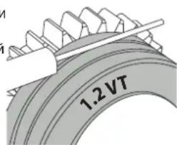

HaanbBnHaHa polnke (npmep: 1.2 VT)
:JIO6IJIYNCIOJIb3OBAHIN
YTO6bI yCTaHOBnTB npcaOCHbI npoBOd, BblONHIne CneDyUOnne DeiCTBn:
- Ocna6bTe pyuKn Do MaKcMMyMa n onyCTNe HX.
- BCTaBbTe npOBd, 3aTeM 3akpoTe nOdaIOuN MEXaHn3M DnBraTeTn 3aTaNTE pyKn, KaK
yka3aHO. - PnBBeNTe B DeIcTBVe DBrTaTeNb c NOMOuBIO KHOKN BKNIOueHnpe3aKa nn KHOKN pyHOn IpaN npoBOJOKn (1-6).

PpmeuHn
CnIuKOM y3kN mHaH MoKET Bb3BaT np6JIeMbIC noaey n nepepeBOM DnRaTeJIA.
KOHHeKToP rOpEnKn DOnKeH TaXe 6bTb XopoWo 3aTHyT Bo N36exKaHne nepepeBa.
- PpOBePbTe, YToBbH Hn npoBoIoka, Hn 6obHa He Kacanncb MexaHnuecknx 6nokOB annapaT. B O6paTHOM cnUyae cyuecTByeT onaCHOCTb KOpOTKOrO 3AmbKaHnR.
PNUCK OXKOROB, CBA3AHHbI C NOBUNKHBIMN 3JEMEHTAMN

IpaIOUIOue yCTpOCTBA IMeIO T NOBnKHbE 3neMeHTbl, B KOTOpble MOryT nonactb pyKn, BOIOcbl, OeJka ININ INHCTpyMeHTbl IN TAKIM oBaPazOM npBecTN KaPHeHnM!
- He npBnKaTe pyKn K NOBnKbIM IIN NOBopaUBaIOUMc 3JeMeHTaM, a TaKke K DeTaIam npuBoDa!
- PocneIte 3a TEM, TTo6b BCE KpbIuK Kopnyca IIn 3auHTbIe KpbIuK 6bln 3akpbITb BO BpempaOb!
He hocnte nepaTkn, kOrda npOeBaTe npoBOJIOky nIIN 3aMeHReTe KaTyUKy.
IONYABTOMATUeCKA CBAPKA CTAJN / HEPKABEIOUEN CTAJN (PEXIM MAF)
AUTOPULSE MoKET CBAPINBaTb CTaIbHyIO npOBONOKy DnAmEtPOM OT 0,6 Do 1,2 MM n npOBONOKy u3 HepXaBeIOuei CtaNN DnAmEtPOM OT 0,8 Do 1,2 MM (II-A).
IcnoB3oBaHne annapata dny cbapkn cTann Tpe6yET cneuPhiueckn ra3 (Ar + CO2).Ponopzra CO2 moKet MeHrbc8 B 3abncmoctn ot Tna nCnoB3yeMoro r3a.Дян HeKpaBekn HcNpO3yIte Cmecb C 2%-codepxahnEM CO2.Пи CBAPKe YHCTbIM CO2 He06XoDMIO NOkKnIOHTb NODPeBaTeB r3a K Ra3OBOMy BaIHOHy.Дян KOHKpeTHbIX Tpe6oBamn K ra3y, noKaanycta, CBKNTeCb BaAMm DCntpn6bIoTOpm Ra3a. PAcxoD r3a npn CBAPKe CTAN OT 8 do 15 /mNIn B 3abxCIMoCTn OT OKpykaioe I cpebl.CHeprIm3B HmnylbChom peKmme ONTHMN3npOBAH DnI CKOpOCTn NotOKaRa3 O 12 do 15 nItpOB B Mmhyt.
Iy n3MepeHn paXoHa ra3a Ha BbXOe ropeJIKN peKOMeHdyETcN cNOJb3OBaTb dONOLHTenbHbI paXoHomep (apT. 053939).
IONYABTOMATUeCKAR CBAPKA AJIOMHINRA (PEXIM MIG)
AUTOPULSE MoKet CBapnBaT aHOMmHHeBvI npOBONky DnAmEtPOM OT 0,8 Do 1,2 MM (II-B).
IcnoIb3OBAHnE annapaTaNpaTaN CbAPKn aIIOHMnN Tpe6yeT cneuΦmueckn ra3 - YcTbI aproH (Ar). IyBaBopa r3a cnpoCtte coBerta
cneuaicnta no npdae ra3a. Pacxod rata npn cbrke aHmHnO T 15 do 20 mHn B 3abncmoCTn O OKpykaooe Cpebl n onbta cbapuika.
CnHepn3M B Nmnybchom pexime ONTNm3npoBaH nra CKopoCTn ntoKa rata 12 do 15 nTpoB mHyTu.
Hnke npBedeHb pa3nHm Mekdy nCnoIb3ObaHne mannapaT da CBapK n TaII n I dI CBAPKn aIOMHHN
-Дя aIIOHMnHn IcNoIb3yIte cneuaJIbHbIe poNKn.
- OtperynpyTe daBHeHne HaxmHbIX poNIOKOB nOdaIOoero MexAHn3Ma Ha MNHMym, YTo6bl He pa3dABNTb PpOBOnOky.
- Kaninllnpy Tpy6ky, npedHa3HaeneHHyD nIe HanpaBneHnI pOboNOKo NT oDaIOcero MexaHm3Ma Do EBpopa3BeMa, HxKHO NcIOJb30BaTb
TOnbko npn cBapKe CTaH/NHePxABeKIM.
- TOpelka : nCnoIb3yIte CneuIaNbHyIO ropeIky dIra aIOMHHN. 3Ta rOpeIka dIra aIOMHHN OCHAeHa TeqHNOHOBbIM WnAHROM, YTo6bl
OrpaHnHTb TpeHr. HE O5PE3ATb WnAhr No KpAIO CTbIa! 3TOT WnAHR NcONlb3yETc Ira HnPaBHeHn IpoBOLOKN OT POJIKOB.
-KoHTaKTHaTpy6ka:nCnoJIb3yIte CNEUIAJbHYO KOHTaKTHyIO Tpy6ky IJRAJIOMMHN,COOTBeTcTBYIOU dyAmET
PnncnoB3oBaHmKpachon mCHeOboOncN (CBapka aHOMHHa) peKoMeHdyETc nNoB3oBaTb akceccyap 90950 (II-C). 3ToT akceccyap n3 hepXabeUe cheTn HappaBnEe Tpy6ky, ynyuwa ee ceHTpnpobAHne n o6neray noaduy npOBolokn.

Bndeo
IONYABTOMATNUECKAR CBAPKA CUSIN CUAL (PEXKIM CBAPKN-NAIKN)
AUTOPULSE mokeT cbapnbTaB npoBOnoky CuSi n CuAl dnaMeTpom ot 0,8 do 1,2 MM.
TakmKe 6pa3oM, KaN dIaCTaIIN, NOJIb3yIteCb KAnIIIpaHIO Tpy6ko I rOpEIKO CO cTaIbHbIM UHaHROM. IJIcBapKn-NAKK INCNOB3yIe
HCTbI apHO (Ar). TaKKe MoXHO nCnOJIb3OBaTb yrIpeOpHyIO oBOnOChy 6e3 KaIIJIJIpaHOr Tpy6Kn, Ka IJIaIIOHMnHa.
NOKJIIOUCHNEI43A
- PnBnHTne noxOaun Cbapouhny peyKTop K ra3OBomy 6aIHOHy. CoeHNHTe ero CO cbapouHbIM annapaTOM c nomoouho JnaHra
(nocTbIeTCB KOMnEKeTe).YcTaHOBtE 2 3aTAAKhBIX XOMyTa, YTO6bI He 6bIOn yTeueK.
-
Y6eHnTeCb, yTo ra30BbI 6aIIIOH HAdExHo yDexKBaETcR, coBIOJdA KpennHeHne cENK TRehePApOpy.
-
OtperynpyTe paXoIra3a c nomouIkoJonecNka Ha peyKtope.
Pometkn: nnynpouenpyepunpoBKn pacxoda rata npBedeNte B deiCTBne BeDyune pOAnKn HaxaTneHn KaHONky ropelkn (ocna6bTe Koneciko
MOTOpN3HpOBaHHoro NOdaIOeRO MEXAHIN3Ma, YTO6bI IPOBONOKa He NOdaBaaLac). MakcImaJIbHOH Hanop r3a. 0,5 MPa (5 6ap).
3TOT anropTM He pa6oTaETnCbApKn B pexnme « No Gas »
PEKOMEHdyEMbIe KOMbHaAUH
| (MM) | TOK (A) ∅ npoboi | KN (MM) CoIIIO (MM) CkOpoCT | ItoKa (I/MnH) | ||
| M/G | 0.8-2 20-100 0 | 8 12 10-12 | |||
| 2-4 100-200 1 | .0 12-15 12-15 | ||||
| 4-8 200-300 1 | .0/1.2 15-16 15-18 | ||||
| 8-15 | 300-500 1.2/1.6 | 16 18-25 | |||
| MAG | 0.6-1.5 | 15-80 | 0.6 | 12 | 8-10 |
| 1.5-3 80-150 0 | 8 12-15 10-12 | ||||
| 3-8 150-300 1 | .0/1.2 15-16 12-15 | ||||
| 8-20 | 300-500 1.2/1.6 | 16 15-18 | |||
PEKIM CBAPKN MIG/MAG (GMAW/FCAW)
WAARSCHUWINGEN - VEILIGHEIDSINSTRUCTIES
ALGEMENE INSTRUCTIES

INTERFACE HUMAN - MACHINE (IHM)

MMI
IEC 60974-1 IEC 60974-10 Class A
L'appareil respecte la norme EN60974-1 et EN 60971-10 appereil de classifie device is complian with standard EN60974-1 and EN60971-10 class A device. Das Geraf erflt die Norm EN 60974-1 und EN 60971-10 der Gerateklasse A El aparato se ajustla la norma EN60974-1 y EN 60971-10, aparato de clase Annapat cootBCTbyET HOPAM EN60974-1 H EN60971-10 annapat knaCa D it klasse A apparaat vdoet aan de EN60974-1 en EN60971-10 normen. Il dispositivo rispetta la norma EN60974-1 e EN 60971-10 dispositiva classe A.
| IEC 60974-5 | FR L'appareil respecte la norme EN 60974-5. EN This product is compliant with standard EN 60974-5. DE Das Gerät entspricht der Norm EN 60974-5. ES El aparato es conforme a las normas EN60974-5. RU Annapat coblmojaert hopmbi EN 60974-5. NL Het apparaat voldoet aan de norm EN 60974-5. IT Il disposittivo rispetto la norma EN 60974-5. |
| FR Ce matériel faisant l'objet d'une collecte sélective selon la directive européenienne 2012/19/UE. Ne pas jeter dans une poubelle domestique! EN This hardware is subject to waste collection according to the European directives 2012/19/EU. Do not throw out in a domestic bin! DE Für die Entsorgung Ihres Gerätes gellen besondere Bestimmungen (sondermüll) gemäß europäische Bestimmung 2012/19/EU. Es dar nicht mit dem Haummüll entsorgt werden! ES Este material requiere una recogida de basuras selecta se-gún la直达eva europea 2012/19/UE. JNo tirar este produits a la basura domestica! RU Θto obórpodanne no déléktrin nepeperabotte cornaccho dipecktnibe Ebrocdoa 2012/19/UE. He biebpaibatb b obssm mycopocboptnik! NL Afzonderlijke inzameling vereist volgens de Europese richtlijn 2012/19/UE. Gooi het apparaat net bij het huishoudelijk afval! IT Questo materiale é soggetto alla raccolta differenziata segundo la dirittiva europea 2012/19/UE. Non smalire coni rifiuti domestici! | |
| FR Produkt recyclable qui relève d'une consigne de tri. EN This product should be recycled appropriately DE Recyclingprodukt, das gesonder entsorgt werden muss. ES Producto reciclable que require une separación determinada. RU Θrot annapat no déléktrn ytmilazoun. NL Product recyclebaar, net bij het huishoudelijk afval gooien IT Prodotto riciclabile soggetto a raccolta differenziata. | |
| FR Marque de conformité EAC (Communauté économique Eurasienne) EN EAEC Conformity marking (Eurasian Economic Community). DE EAC-Konformitätszeichen (Eurasische Wirtschaftsgemeinschaft) ES Marca de conformidad EAC (Comunidad económerica euroasiática). RU Θnak cootbetctbna EAC (Ebrassinkoe ekonomnieckoe coobüectvo) NL EAC (Eurazialische Economische Gemeenschap) merkteken van overeenstemming IT Marca di conformità EAC (Comunità Economica Eurasiatica) | |
| FR Information sur la température (protection thermique) EN Temperature information (thermal protection) DE Information zur Temperatur (Thermoschutz) SE Informação sobre la temperatura (protection térmica) RU Inφormaúnia no tempepatyne (termpozaúnta). NL Informatie over de temperatuur (thermische bevelling) IT Informazione sulla temperatura (protezione termiche) | |
| FR Entrée de gaz EN Gas input DE Gaseingang ES Entrada de gas RU Μoçau ra3a NL Ingang gas IT Entrata di gas | |
| FR Polarité (+)/(-) EN Polarity (+)/(-) DE Polarità (-) ES Polaridad (+)/(-) RU Μolapnoctb (-) NL Polariteil (+)/(-) IT Polarità (+)/(-) | |
| FR Marche (mise sous tension) / Arrêt (mise hors tension) EN On (power on) / Off (power off) DE Ein (Einschallen) / Aus (Ausschallen) ES On (encendido) / Off (apagado) RU Bkn (Bknoucheine) / Bkvkn (Bknoucheine) NL Aan (stroom aan) / Uit (stroom uit) IT On (accensione) / Off (spegnimento) | |
| FR Protégé contre l'accès aux parties dangereuses des corps solides de diam >12,5 mm et protégé contre la plule dirigeée à 60° par rapport à la verticale lorsque les parties mobiles de l'appareil ne sont pas encore en fonctionnement. EU Protected against access to dangerous parts of solid bodies with diam >12,5 mm and protected against rain directed at 60° to the vertical when the moving parts of the device are not yet in operation. DE Geschütz gegen den Zugang zu gefährlichen Teilen von festen Körpern mit einem Durchmesser >12,5 mm und geschützt gegen Regen, der unter einem Winkel von 60° zur Senkrechten gerichtet ist, wenn die beweglichen Teile des Geräts noch nicht in Betrieb sind. ES Protegado contra el accesso a partes peligrosas de cueros solidos de diametro >12,5 mm y protegidio contra la lluvia dirigida a 60° con besoin o. Spagado a la vertical cuando las partes moviles del dispositivo ain no estan en funzioniamento. RU 3aeta tme opdtyma k onasbnchm nactr Tverbix Tnel dmametrom >12,5 MM n haizeta ot To doxjda. Haprabvenhoro pod ytmol 60° k Bertinkain, korgla dbnkyuzmece cactny uystrojctbva eune he pabotaoj. NL Beschemd tergen de toegang tot gevaartijke delen van vaste lichamen met een diameter >12,5 mm en beschemd tergen regen under een hoek van 60° ten opzichte van de vertical wonneer de bewegende delen van het toestel nog nit in werkinq zijn. IT Protetto contro l'acceso a parti pencolose di corpi solidi con diam >12,5 mm e protetto contro la pioggia diretta a 60° rispetto alla verticale quando le parti mobili del dispositivo non sono alcora in funzione. | |
| FR Purge gaz EN Gas purgege DE Gasventil einschalten ES Epurazione del gas RU Ipoydubka B3oporom NL Afvoeren gas IT Gas del lavaggio PT Purga de gás |
GYS
Tolerance I (courant)
Tolerance U (tension)
Identification - Options ON
This interface (HMI) manual forms part of the complete documentation. A general manual is included with the product. Read and follow the general manual's instructions, particularly the safety instructions!
Only for use with the following products:
AUTOPULSE

Version du logiciel
This user manual describes the following software versions:
1.86.
The software's version can be found on the main menu: Information / MMI
Using the device
The main screen contains all the necessary information for the entire welding process, including the pre-, mid- and post-welding phases (the interface may change slightly depending on the selected process).
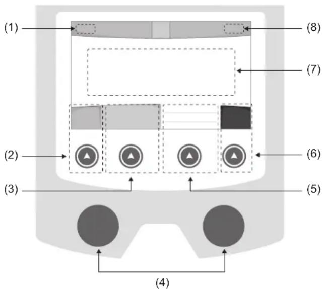
(1)User name/Traceability
(2) Push button n°1: Main menu or return to the previous menu
(3) Push button n°2 : Current Welding Process Settings
(4) Navigation buttons
(5)Push button n^3 :Settings
(6)Push button n^4 :Job or Validation
(7) Current settings
(8) Voltage, Current and Power Readings
Main menu
The main menu screen is displayed when the product is first started.
Navigating between the different sections is done using the dials and buttons.
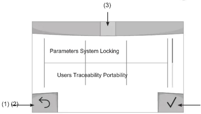
(1) Back
(2) Validation
(3) The current section's computer icon
Settings (User settings)
Display mode
- Easy: reduced display and functionality (no access to the welding cycle).
- Expert: full display, allows the user to adjust the timing of the different welding cycle phases.
- Advanced: full display, allows the user to adjust all the welding cycle settings.
Language
Choice of the interface language (English, French, German, etc).
Units of measurement
Choice of measurement units: International (SI) or Imperial (USA).
Material naming
European standard (EN) or American standard (AWS).
Brightness
Adjusts the interface screen's brightness (setting from 1 [very dark] to 10 [very bright]).
User Code
Customise the user's access code to safely lock the machine (default 0000).
Tolerance I (current)
Current tolerance control:
OFF: Freely adjustable, the current setting is not limited.
± 0A : no tolerance, current limitation.
± 1A > ± 50A : The setting range at which the user can adjust their current.
Tolerance U (voltage)
Voltage tolerance control:
OFF: freely adjustable, the voltage setting is not limited.
± 0.0V : no tolerance, voltage limiting.
± 0.1V > ± 5.0V : setting range at which the user can vary the voltage.
Tolerance wire speed)
Wire speed setting tolerance (m/min):
OFF: freely adjustable, wire speed setting is not limited.
± 0.0m / min : no tolerance, wire speed control.
± 0.1m / min > ± 5.0m / min : setting range at which the user can vary the wire speed.
Using the machine's System
Naming Device Interface
Information about the device's name and the option to customise it can be reached by pressing on the interface.
Clock
Setting the time, date and format (AM/PM).
Reset
Pressing 'Reset' will reset the machine's settings:
- Partial: will reset the default value of the present welding process.
- Total: Will reset all the device's configuration data to the factory settings.
Locking
This machine's interface screen can be locked to protect any work in progress and prevent unintentional or accidental changes. The current settings window can still be modified with the settings chosen in the Settings menu (see previous page). All other functions are inaccessible.
To unlock the interface, press push button #1 and enter your 4-digit user code (default 0000).
Users
The user mode enables the machine to be shared between several users. The first time that the machine is started, it will be in Admin mode. The administrator can create user profiles. Each user has his own setup (mode, setting, process and JOBs etc.) and this cannot be modified by another user. Each user needs a personal four-digit code in order to sign in to the machine.
- The administrator has access to the entire general menu.
- Users have access to a simplified interface. Users do not have the ability to delete information (Tracking, Jobs, User profiles, etc).
User configuration interface (reserved for the administrator).
The left side of the screen lists the users. The administrator has the ability to sort these users by name or by date by quickly pressing button n°2. Pressing this button for a prolonged time will delete the active user(s) instead (although the Admin account cannot be deleted).
On the right side of the screen, you can see the details of all the users previously created with the following information: Avatar, Name, Team No. and Tolerance (%) .
Creating a user profile
Press button n°3 to create a new user.
-User:Customise the user's name by pressing push button n^3
-Avatar:Choice of avatar colour
- Team : Assignment of the team number (10 max)
-Usercode:personalaccesscode(default0000)
- Current setting tolerance I:
OFF: freely adjustable, the current setting is not limited.
± 0.0A : no tolerance, limiting the current (not recommended).
± 0.A > ± 50A : Setting interval at which the user can vary their current.
- Voltage setting tolerance U:
OFF: freely adjustable, the voltage setting is not limited.
± 0.0V : no tolerance, limiting the voltage (not recommended).
± 0.1V > ± 5.0V : setting range at which the user can vary the voltage.
- Wire speed setting tolerance (m/min):
OFF: freely adjustable, the wire speed setting is not limited.
± 0.0m / min : no tolerance, limiting the wire speed (not recommended).
± 0.1m / min > ± 5.0m / min : the range of settings at which the user can vary the wire speed.
It is not possible to change the admin name or avatar for the «Admin» user.
Changing a user profile
Select the user on the left side of the screen and press the push button n^4
Selecting users
If one or more user profiles are created, the user block displays all of the machine's users.
Select the user of your choice and press to confirm the choice. You will be asked for an unlock code.
The «Close» feature locks the machine on the user's choice so that no other settings are accessible. This screen remains the same when the machine is switched on (OFF -> ON switch).
User display
The active avatar and username are displayed at the top left of the screen.
Unlocking code
Each user profile is protected by a personal, four-digit code. The default code will be 0000 if not changed. After failing to correctly enter your personal code three times, the interface will be blocked and you will be asked for an unlock code. This code is made up of six digits and cannot be changed. It is: 314159.
Using the machine's Tracking interface
This welding management interface allows you to track/record every step of the welding operation, bead by bead, during any industrial operation. This quality-driven approach ensures high post-production welding quality through analysis, evaluation, reporting and documentation of the recorded welding settings. This feature allows for the accurate and fast collection and storage of data required under EN ISO 3834. This data can be recovered and exported to a USB stick.
1- Start - Creating a tracking system
- Personalise the site's name by pressing push button n^3 .
- Sampling interval :
- Hold: No recording of current/voltage values (average along the wire) during welding.
- 250 ms, 500 ms, etc.: Recording of the current/voltage values (average along the wire) every X milliseconds or seconds during welding.
- Options - OFF: simple tracking
- Options - ON: full tracking
Pass counter (ON/OFF)
Weld counter (ON/OFF)
Temperature (ON/OFF): Temperature of the part to be welded at the beginning of the weld bead.
Length (ON/OFF): Length of the wire (units of measurement are displayed according to the choices made in Settings/Units of Measurement).
Variable(s): allows you to add additional personalised information (weight, notes, wire speed, etc.).
Press to start tracking.
Tracking display
At the top left of the screen, the job name and the bead number are displayed (the bead number goes up automatically and cannot be changed).
Identification - Options ON
At the end of each bead, an identification window appears: Pass N^ , Weld N^ , Part temperature and/or Bead length.
Validation
Confirmation can be done on the HMI or by pressing the torch's trigger.
Stop - Stop tracking
To stop tracking during a welding process, the user must return to the Tracking block and select «Stop».
Export
The recovery of this information is done by exporting the data to a USB stick.
The CSV data can be processed with a spreadsheet program (Microsoft Excel®, Calc OpenOffice®, etc).
The file name is linked to the machine name and serial number.
2- Start -Tracking management
The left-hand side of the screen lists previously created work sites.
The user has the possibility to sort these worksites by name or by date by quickly pressing button n°2. Holding down this button will delete the active job or all jobs.
The right-hand side of the screen shows the details of each of the previously created jobs with the following information: sampling frequency, number of recorded welds, total welding time, welding energy supplied, setup of each weld (process, timestamp, welding time and welding U-I).

Rec
Creation of a tracking system (see previous paragraph)
Start the active site's tracking system
Portability
Import Setup.
Upload the machine settings from a USB memory stick (directory: Removable Disk\PORTABILITY\CONFIG) to the machine. Press and hold to delete the settings on the USB stick.
Export Configuration
Export the machine settings to a USB stick (directory: Removable Disk\PORTABILITY\CONFIG)
Import Job
Importing Jobs to the machine according to the processes available in the USB key's Removable Disk directory.
Export Job
Exporting jobs from the machine to a USB stick according to the processes (directory: Removable Disk|PORTABILITY|JOB). Caution, older jobs on the USB stick may be deleted.
To prevent data loss during data import or export, do not remove the USB flash drive or turn off the machine. The file name is linked to the machine name and serial number.
Calibration
Calib. Speed
Feature designed to calibrate the speed of the motorised reel. The purpose of calibration is to compensate for variations in reel speed in order to adjust the displayed voltage measurement and to refine the energy calculations.
The procedure, once started, is explained with an animation on the screen.
Calibration of the motorised reel speed must be done regularly to ensure optimal welding.
Information
Setup data of the product's system components:
- Model
- Serial number
Device name - Software version
- Job and Synergies (preinstalled user settings) used.
Pressing any push button will exit the information screen.
Job memories and reminders
Can be accessed via the «JOB» icon on the main screen.
The settings in use are automatically saved and remembered the next time you turn on the machine.
In addition to the current settings, it is possible to save and remember so-called «JOB» settings.
There are 500 JOBS for the MIG/MAG and TIG processes, as well as 200 for the MMA process. Data storage is based on the current process settings, the current settings and the user profile.
Job
This JOB mode enables JOBs to be created, saved, remembered and deleted.
Quick-Load - Recall JOBs from the trigger when not welding.
Quick Load is a non-welding JOB recall mode (20 max) and only possible in MIG-MAG and TIG processes.
From a list of previously created JOBs, JOB recalls are done by short trigger presses. All trigger modes and welding modes are supported.
Error codes
The following table shows a non-exhaustive list of messages and error codes that may appear.
Carry out these checks and controls before contacting an authorised GYS technician.

If the user needs to open the product, they must turn off the power supply by unplugging the electrical plug and waiting two minutes for safety.
| Error codes | Messages Solutions | |
| 001 | OVER VOLTAGE FAULTCheck the electrical installation | Have your electrical installation checked by an authorised person. |
| 002 | UNDERVOLTAGE FAULTCheck the electrical installation | |
| 005 Earth current fault. | There is a stray current. Check the wiring of the welding accessory (torch, earth clamp, electrode holder, etc.) | |
| 010 | GENERATORThermal protection | Wait a few minutes for the power source to cool down. Ensure that the recommended duty cycle for the welding current used is not exceeded. Thermal protection Ensure that the air inlets and outlets are not obstructed. Installing a dust filter (ref. 063143). Please note that the dust filter reduces the duty cycle. |
| 011 | FanFan fault | Fan Switch off the power supply by unplugging the electrical plug and check the fan. Ensure that the fan is not blocked. |
| 012 | TRIGGERThe trigger is pressed. | Remove the torch and check that the message is still applicable Check that the «Gas purge / Wire feed» switch is not obstructed or stuck. Check that the MIG/MAG torch trigger is not obstructed or stuck. |
| 015 | MOTORUnable to reach the required speed | Check the pressure settings of the motorised reel rollers. Check that the filler wire is not blocked in the torch sheath. If it is Impossible to reach the requested speed, calibrate the speed of the motorised wire reels (Menu «Calibration»). |
| 019 | If overloaded, please check your settings. Release the trigger to clear | Check the power source's settings and the machine's installation (filler wire, rollers, etc.)If the problem persists, carry out an update (Via Planet GYS). |
| 020 | Welding start problemPlease check your welding parametersPress and release the trigger to clear. | Check the power source's settings and the machine's installation (filler wire, rollers, etc.)If the problem persists, carry out an update (Via Planet GYS). |
| 024 | USB overload Unplug your USB. | Change the USB stick. |
| - | An internal system error has occurred. Please restart your machine | Restart your machine by turning the machine off and on again. If the problem persists, carry out update (via Planet GYS) |
| - Error during motor calibration Recalibrate the motor reel speed (Menu «Calibration») | ||
| - Error during calibration Recalibrate the welding cables (Menu «Calibration») | ||
| - No more memory space in the machine Delete Jobs to free | up the internal storage space. | |
| - | Unsupported files %s Err %d Continue anyway? | The data on the USB stick is corrupted. |
| - Unable to save to the USB stick | Free up space on the USB stick. If the problem persists, change the USB stick. | |
| - | Number of attempts exceeded. Unlock code required | Enter unlock code: 314159 |
| - | Wrong user code | Wrong user code If the personal code is wrong, enter the correct code. By default, this code is 0000. |
If an unlisted error code appears or your problems persist, contact GYS Customer Service.
Warning icons
The alert icons at the top right of the screen provide you with more information about your product.
| Warning Meaning | |
| DEMO | Alert meaning the machine is in Demonstration mode. Check your electrical installation (mains voltage). |
| End-of-life interface battery. Change the battery (CR2032) and update the [product's date and time (System / Clock). | |
| The fan is not running at the right speed. Check the fan's condition. | |
Export Job (Export von Jobs)
CyeTuk CBapKn (ON/OFF)
TemnepaTypa (ON/OFF): TemnepaTypa cBapuBaemoi DeTani B hauane cbapouHoro Wba.
Динha (ON/OFF):Динha shhya (eDHHNcbl n3MepeHnO TOp6paKaOTcB COOTBeTCTBnC Bbl6opom, cdeNaHHbIM B HAcToPouK/EDHHNcbl n3MepeHn).
Ipeemehna(ble): no3BOJnE TdoabnTb DOnONHnTeNbHyIO NOJB3OBaTeJbCKyIO HOpMaunio (Bec, aHHotaun, ckopocTb npoBOJOKN t.d.)
HaxMNTe VTO6bl HaaytB OTCnEKNBaHne.
OTo6paXeHne npocJexKuBaEmoCTn
B BepxHem IeBOM yIy 3KpaHa OTo6pKaIOTCa Ha3BaHne Uexa N HOpE npoBOda (HOpE npoBOda BBOHTcA ABTOMaTUnCeCKN IN He MoKeT 6bITb N3MeHe).
INDnkaun -Onnn ON
B KOHue KaJDoRo 1Ba NOBnREcra OKHO NDeHTnФkaun: HOpE npoxoJa, HOpE cBapHoro 1Ba, TempepaTa3aROTOBKn n/nnn DnHa npOBOda.
Повтберждениe
IopTBePxJdHHe MoKET 6bITb BbINOnHeHa HA IHM nn HaxKaTneH Ma TprIrep RopeNk.
CTON - OctaHOBKa OTCJexKuBaHnA
YTO6bIOCTAHOBNTbOTCNEXKBAEMOCTBHa 3Tane CBAPKN,NOJB3OBATEJIb DOnJKeH BepHyTbCByB 6JOK
《OTCnHexKBAeMOCTb》N Bbl6paTb《OCTaHOBNTb》
3KcnpTnpoBaTb
IOnyehne 3To HnΦopMaun npon3BODNTcnyTEM 3KcnpTa daHbIX Ha KInou USB.
Ha3aHue dokymehma coomcmyem Ha3aHuO MaunuHbU ee cepuHomy Homepy.
2- Start - Co3dahne oTcJIeKINBaEMOCTn
B JEBOY qactn 3KpaHa nepeuCJIeHbI paHee co3JaHbI cTpOnTeJbHbI nNoJzAdKn.
IOnb30BaTeB IMeET BO3MOXHOCTb COPTnPOBaTb NO HA3BaHnIO NnIO NaTe KopoTKO HaxKa H KONky KNaBnAtpyb n°2.
DionrOe Haxkata He 3Tu KhoNky no3BOJarey dAnITb AKTNBbHbI pa6ooye MeCTO nIN BCE pa6ooye MeCTa.
B npaboi yactn 3kpaHa moKHO npocmoTpeb deTaN KaKdoRo n3 paHee co3daHbIX pa6oynx Mect co cneDyUoey HΦopMaueNe: yactota Bb6OpKn, KOINueCTBO COXpAHHeHHbx WBOB, oBua JPODOJHXTeNbHOCTB CBAPKn, KOHNpyaunna NapametpoB KaKdoRo IBa (MeToD CBAPKn, ABTomATNueCKoe IpocTabHeHne DaTbI N BPemEHN, PPODOJHXTeNbHOCTB CBAPKn u-1CBapKn).

3anncb
Co3dahne oTcIeXnBaemoctB
3KcnpTnpoBaTb KoHOpnpyaunIO
3Kcnpot KOHpUpyaun MaunHbHa USB KapTy (kataor: CbeMhbu duck MObunbHocmb Hacmpouku)
3arpy3ntbJob
IIMnpt Jobs B COOTBETCTBm C npoueDypamH, HaxoJauimncB KaTalore Removable disk \ Portability c USB-Klouha
KOMNbIOTep.
3KcnpTnpoBaTb Job
3KcnpT 3aAHH n3 annapata Ha USB hakonnteB B COOTBeTCTBnC npoueDypAMN (kataJor: CbemHbU duckMoBunbHocmb Job)
BHumaue, cmapbte 3adaHua Ha USB Kapme, mozym 6bimy ydaenbl.
UTo6bI n36exaTb Notepn DaHbIX npn NMnopTe nn EKcnopTe daHHbx, He n3BneKaite USB-Hakonnte Ih Ne BbIKnouaTe annapat. Ha3eaHue DokyMeHa coomeemcmyem Ha3eaHIO MaunHbI u ee cepuiHomy Homepy.
KannibpoBka
KaJIb6pOBka CkOpocTb
Функц,在нднаньнгдяКалбрвсКорocTmMexaHn3MaNoDAHINPpOBONK。JIbkoKanl6pOBKnYBJIeTcKOMNehcaunI3MeHeHnДINHbCBAPOHybIXKaBeNeCTeM,UTo6blOTKOppeKTHpOBaTB3aMep aDnHpyEmoHapJxHnIyUnHb paChETAhePnn.10ce3anycka npoucecca,OHOTOppaKaTeHa3kpaHecAnHmauee.
Ig oecneueHn ONTMaJIbHO CBAPK Heo6xOIMo nepnoDnueckn npOBODHT KaIIbpoBky ckopocTn BpaueHna 6apabana dBriratela.
HΦopMaçña
ДаHHье HabtpoIGN CnCTeMHbIX KOMNoHErTOB IpoJyKtA:
-MoJenb
- CepinHbH Homep
- HazbaHne annapapa
-BercnIPO
-Pa6oTaHINcNoIb3yEmbIe CnHeprnn
Haxamue IIO6O KHOKU npueedem K bIXOy u3 UHOpMaUOHHo2O 6noka.
CoxpaheHne n Bbl3OB n3 namTn konhngypaun JOBs
Дocупен чере зйонку «JOВ» на ос hobом заразе.
Bo BpemnncnoB30BaHnnpaMeTpblABToMaTHueckn CoXpaHryOTcN BocCTaHaBnBaIOTc PnCneDyUeEM BKJIIOHeHN.
ПOMМО TEKUYUNI napametpoB,MOXHOCoxpaHrTb N Bbl3bIbA Tb KOHpMIRpyaUNI «JOB».
Ectb 500 KoHpyaun JOBS nIy MeToIOB MIM/MAM TIN 200 dNMA XpaHeHne oChOBaHO Ha npaMeTpax Tekyuero npocecca, Tekuixn HAcTpoek n npoqnn nonb3ObaTeTn.
JOB
PexMM JOB no3BOJnREt CO3daBaTb, COxpaHrTb, ydaJIbTb N Bbl3bIaTb KOHpMrypaun JOB.
QUICK LOAD-BbI3OB KOHΦnrgpaun JOBc nOMoUTo TpNiTrepa BHe CBapKn.
Quick Load - 3TO pexim Bbl0Ba KOHpIpyaun JOB (MaKc. 20) BHe CBapOHHo Ipocecca N KOTOpbN Bo3MOKeH ToJIbKO B peXIMe MIG-MAG n TIG.
Bb3OB KOHnpyaun JOB n3 npeBapntelbHo co3daHORo cncsKa KOHnpyaunm JOB, npou3BOuNTcK oPOTKM haxaTneM Ha Tpnrrep. Bce TpnrrepHble pexMbI n peXMBI CBAPKn noDepxNBAOTcR.
KoД oшибкn
B cIeDyUoSe Ta6nue npBVeH eNoJhB cnCoc coo6eHn I KOOB ow6ok, KOTOpbIe MoryT NOBtbcra.
BbnoJHnTe 3Tn npOBepKn KOHTpoJIb nepeI TeM, KaK BblBaTb aBTOpN3OBAHHO rcePbUcHOro cneuaHncta GYS.

Ecn nno3oBATEHNO Heo6xOIMBOCKpbITb 3dene, 08a3aTeIbHO Heo6xOIMO OTKIOHTb annapat OT pO3eTKN, IN NOOXdaTb 2 MNHybl dla 6eONaCHOCTN.
Ecnn noBnTcH He3apeHCTpnpoBaHHb KOD Own6Kn Nn Baan npo6neMbHe nCye3aOT, CBxKntecb c SAV GYS
Иконки педунрекдени (Warning)
3NaUpNpeDpynpExHnB BepxHe npaBoy qactn 3KpaHa daIOT HΦopMaunO BaWem npoDyKe.