Progys 220E FV CEL - Welding machine GYS - Free user manual and instructions
Find the device manual for free Progys 220E FV CEL GYS in PDF.
User questions about Progys 220E FV CEL GYS
0 question about this device. Answer the ones you know or ask your own.
Ask a new question about this device
Download the instructions for your Welding machine in PDF format for free! Find your manual Progys 220E FV CEL - GYS and take your electronic device back in hand. On this page are published all the documents necessary for the use of your device. Progys 220E FV CEL by GYS.
USER MANUAL Progys 220E FV CEL GYS
natural_image
Technical line drawing of a portable electronic device with control knobs and buttons (no text or symbols)FR 02-14 / 106-112
EN 15-27 / 106-112
DE 28-40 / 106-112
ES 41-53 / 106-112
RU 54-66 / 106-112
NL 67-79 / 106-112
IT 80-92 / 106-112
PL 93-105 / 106-112
PROGYS 220E FV CEL
MMA (SMAW) and TIG (GTAW) welding machine
INSTALLATION – FONCTIONNEMENT PRODUIT
INTERFACE HOMME MACHINE (IHM) (FIG-2)
text_image
DispswitchMESSAGES D'ERREUR, ANOMALIES, CAUSES, REMÈDES
Read and understand the following safety recommendations before using or servicing the unit. Any change or servicing that is not specified in the instruction manual must not be undertaken.
The manufacturer is not liable for any injury or damage caused due to non-compliance with the instructions featured in this manual. In the event of problems or uncertainties, please consult a qualified person to handle the installation properly.
ENVIRONMENT
This equipment must only be used for welding operations in accordance with the limits indicated on the descriptive panel and/or in the user manual. The operator must respect the safety precautions that apply to this type of welding. In case of inedaquate or unsafe use, the manufacturer cannot be held liable for damage or injury.
This equipment must be used and stored in a place protected from dust, acid or any other corrosive agent. Operate the machine in an open, or well-ventilated area.
Operating temperature:
Use between -10 and +40°C (+14 and +104°F).
Store between -20 and +55°C (-4 and 131°F).
Air humidity:
Lower or equal to 50% at 40°C (104°F).
Lower or equal to 90% at 20°C (68°F).
Altitude:
Up to 1000 meters above sea level (3280 feet).
INDIVIDUAL PROTECTIONS AND OTHERS
Arc welding can be dangerous and can cause serious and even fatal injuries.
Welding exposes the user to dangerous heat, arc rays, electromagnetic fields, noise, gas fumes, and electrical shocks. People wearing pacemakers are advised to consult with their doctor before using this device.
To protect oneself as well as the other, ensure the following safety precautions are taken:

In order to protect you from burns and radiations, wear clothing without cuffs. These clothes must be insulated, dry, fireproof and in good condition, and cover the whole body.

Wear protective gloves which guarantee electrical and thermal insulation.

Use sufficient welding protective gear for the whole body: hood, gloves, jacket, trousers... (varies depending on the application/operation). Protect the eyes during cleaning operations. Do not operate whilst wearing contact lenses.
It may be necessary to install fireproof welding curtains to protect the area against arc rays, weld spatters and sparks. Inform the people around the working area to never look at the arc nor the molten metal, and to wear protective clothes.

Ensure ear protection is worn by the operator if the work exceeds the authorised noise limit (the same applies to any person in the welding area).
Stay away from moving parts (e.g. engine, fan...) with hands, hair, clothes etc...
Never remove the safety covers from the cooling unit when the machine is plugged in - The manufacturer is not responsible for any accident or injury that happens as a result of not following these safety precautions.
The pieces that have just been welded are hot and may cause burns when manipulated. During maintenance work on the torch or the electrode holder, you should make sure it's cold enough and wait at least 10 minutes before any intervention. The cooling unit must be on when using a water cooled torch in order to ensure that the liquid does not cause any burns.
ALWAYS ensure the working area is left as safe and secure as possible to prevent damage or accidents.
WELDING FUMES AND GAS

The fumes, gases and dust produced during welding are hazardous. It is mandatory to ensure adequate ventilation and/or extraction to keep fumes and gases away from the work area. An air fed helmet is recommended in cases of insufficient air supply in the workplace.
Check that the air intake is in compliance with safety standards.
Care must be taken when welding in small areas, and the operator will need supervision from a safe distance. Welding certain pieces of metal containing lead, cadmium, zinc, mercury or beryllium can be extremely toxic. The user will also need to degrease the workpiece before welding.
Gas cylinders must be stored in an open or ventilated area. The cylinders must be in a vertical position secured to a support or trolley.
Do not weld in areas where grease or paint are stored.
FIRE AND EXPLOSIONS RISKS

Protect the entire welding area. Compressed gas containers and other inflammable material must be moved to a minimum safe distance of 11 meters.
A fire extinguisher must be readily available.
Be careful of spatter and sparks, even through cracks. It can be the source of a fire or an explosion.
Keep people, flammable objects and containers under pressure at a safe distance.
Welding of sealed containers or closed pipes should not be undertaken, and if opened, the operator must remove any inflammable or explosive materials (oil, petrol, gas...).
Grinding operations should not be directed towards the device itself, the power supply or any flammable materials.
GAS BOTTLE

Gas leaking from the cylinder can lead to suffocation if present in high concentrations around the work area.
Transport must be done safely: Cylinders closed and product off. Always keep cylinders in an upright position securely chained to a fixed support or trolley.
Close the bottle after any welding operation. Be wary of temperature changes or exposure to sunlight.
Cylinders should be located away from areas where they may be struck or subjected to physical damage.
Always keep gas bottles at a safe distance from arc welding or cutting operations, and any source of heat, sparks or flames.
Be careful when opening the valve on the gas bottle, it is necessary to remove the tip of the valve and make sure the gas meets your welding requirements.
ELECTRIC SAFETY

The machine must be connected to an earthed electrical supply. Use the recommended fuse size.
An electrical discharge can directly or indirectly cause serious or deadly accidents.
Do not touch any live part of the machine (inside or outside) when it is plugged in (Torches, earth cable, cables, electrodes) because they are connected to the welding circuit.
Before opening the device, it is imperative to disconnect it from the mains and wait 2 minutes, so that all the capacitors are discharged.
Do not touch the torch or electrode holder and earth clamp at the same time.
Damaged cables and torches must be changed by a qualified and skilled professional. Make sure that the cable cross section is adequate with the usage (extensions and welding cables). Always wear dry clothes in good condition, in order to be insulated from the electrical circuit. Wear insulating shoes, regardless of the environment in which you work in.
EMC CLASSIFICATION
These Class A devices are not intended to be used on a residential site where the electric current is supplied by the public network, with a low voltage power supply. There may be potential difficulties in ensuring electromagnetic compatibility on these sites, because of the interferences, as well as radio frequencies.
Provided that the impedance of the low-voltage public electrical network at the common coupling point is less than Zmax = 0.246 Ohms, this equipment complies with IEC 61000-3-11 and can be connected to public low-voltage electrical mains. It is the responsibility of the installer or user of the equipment to ensure, in consultation with the distribution network operator if necessary, that the network impedance complies with the impedance restrictions.
This equipment complies with the IEC 61000-3-12 standard.
ELECTROMAGNETIC INTERFERENCES
The electric currents flowing through a conductor cause electrical and magnetic fields (EMF). The welding current generates an EMF field around the welding circuit and the welding equipment.
The EMF fields may disrupt some medical implants, such as pacemakers. Protection measures should be taken for people wearing medical implants. For example, access restrictions for passers-by or an individual risk evaluation for the welders.
All welders should take the following precautions in order to minimise exposure to the electromagnetic fields (EMF) generated by the welding circuit::
- position the welding cables together – if possible, attach them;
- keep your head and torso as far as possible from the welding circuit;
- never enroll the cables around your body;
- never position your body between the welding cables. Hold both welding cables on the same side of your body;
- connect the earth clamp as close as possible to the area being welded;
- do not work too close to, do not lean and do not sit on the welding machine
- do not weld when you're carrying the welding machine or its wire feeder.

People wearing pacemakers are advised to consult their doctor before using this device.
Exposure to electromagnetic fields while welding may have other health effects which are not yet known.
RECOMMENDATIONS TO ASSESS THE WELDING AREA AND WELDING INSTALLATION
Overview
The user is responsible for installing and using the arc welding equipment in accordance with the manufacturer's instructions. If electromagnetic disturbances are detected, it is the responsibility of the user of the arc welding equipment to resolve the situation with the manufacturer's technical assistance. In some cases, this remedial action may be as simple as earthing the welding circuit. In other cases, it may be necessary to construct an electromagnetic shield around the welding power source and around the entire piece by fitting input filters. In all cases, electromagnetic interferences must be reduced until they are no longer bothersome.
Welding area assessment
Before installing the machine, the user must evaluate the possible electromagnetic problems that may arise in the area where the installation is planned.
In particular, it should consider the following:
a) the presence of other power cables (power supply cables, telephone cables, command cable, etc...) above, below and on the sides of the arc welding machine.
b) television transmitters and receivers ;
c) computers and other hardware;
d) critical safety equipment such as industrial machine protections;
e) the health and safety of the people in the area such as people with pacemakers or hearing aids;
f) calibration and measuring equipment
g) The isolation of the equipment from other machinery.
The user will have to make sure that the devices and equipments that are in the same room are compatible with each other. This may require extra precautions;
h) make sure of the exact hour when the welding and/or other operations will take place.
The surface of the area to be considered around the device depends on the building's structure and other activities that take place there. The area taken in consideration can be larger than the limits determined by the companies.
Welding area assessment
Besides the welding area, the assessment of the arc welding systems installation itself can be used to identify and resolve cases of disturbances. The assessment of emissions must include in situ measurements as specified in Article 10 of CISPR 11. In situ measurements can also be used to confirm the effectiveness of mitigation measures.
RECOMMENDATION ON METHODS OF ELECTROMAGNETIC EMISSIONS REDUCTION
a. National power grid: The arc welding machine must be connected to the national power grid in accordance with the manufacturer's recommendation. If interferences occur, it may be necessary to take additional preventive measures such as the filtering of the power supply network. Consideration should be given to shielding the power supply cable in a metal conduit. It is necessary to ensure the shielding's electrical continuity along the cable's entire length. The shielding should be connected to the welding current's source to ensure good electrical contact between the conduct and the casing of the welding current source.
b. Maintenance of the arc welding equipment: The arc welding machine should be submitted to a routine maintenance check according to the manufacturer's recommendations. All accesses, service doors and covers should be closed and properly locked when the arc welding equipment is on.. The arc welding equipment must not be modified in any way, except for the changes and settings outlined in the manufacturer's instructions. The spark gap of the arc start and arc stabilization devices must be adjusted and maintained according to the manufacturer's recommendations.
c. Welding cables: Cables must be as short as possible, close to each other and close to the ground, if not on the ground.
d. Electrical bonding : consideration should be given to bonding all metal objects in the surrounding area. However, metal objects connected to the workpiece increase the riskof electric shock if the operator touches both these metal elements and the electrode. It is necessary to insulate the operator from such metal objects.
e. Earthing of the welded part: When the part is not earthed - due to electrical safety reasons or because of its size and its location (which is the case with ship hulls or metallic building structures), the earthing of the part can, in some cases but not systematically, reduce emissions. It is preferable to avoid the earthing of parts that could increase the risk of injury to the users or damage other electrical equipment. If necessary, it is appropriate that the earthing of the part is done directly, but in some countries that do not allow such a direct connection, it is appropriate that the connection is made with a capacitor selected according to national regulations.
f. Protection and plating : The selective protection and plating of other cables and devices in the area can reduce perturbation issues. The protection of the entire welding area can be considered for specific situations.
TRANSPORT AND TRANSIT OF THE WELDING MACHINE

The machine is fitted with handle(s) to facilitate transportation. Be careful not to underestimate the machine's weight. The handle(s) cannot be used for slinging.
Do not use the cables or torch to move the machine. The welding equipment must be moved in an upright position.
Do not place/carry the unit over people or objects.
EQUIPMENT INSTALLATION
Rules to follow:
- Put the machine on the floor (maximum incline of 10^ .)
- Ensure the work area has sufficient ventilation for welding, and that there is easy access to the control panel.
- The machine must be placed in a sheltered area away from rain or direct sunlight.
- The machine must not be used in an area with metal dusts.
- The machine protection level is IP23, which means :
- Protection against access to dangerous parts from solid bodies of a ≥12.5mm diameter and,
- Protection against the rain inclined at 60% towards the vertical.
These devices can be used outside in accordance with the IP23 protection index.
- The power cables, extensions and welding cables must be fully uncoiled to prevent overheating.

The manufacturer does not incur any responsibility regarding damages to both objects and persons that result from an incorrect and/or dangerous use of the machine.
MAINTENANCE / RECOMMENDATIONS

- Maintenance should only be carried out by a qualified person. Annual maintenance is recommended.
- Ensure the machine is unplugged from the mains, and wait for two minutes before carrying out maintenance work. DANGER High Voltage and Currents inside the machine.
- Remove the casing 2 or 3 times a year to remove any excess dust. Take this opportunity to have the electrical connections checked by a qualified person, with an insulated tool.
- Regularly check the condition of the power supply cable. If the power cable is damaged, it must be replaced by the manufacturer, its after sales service or an equally qualified person.
- Ensure the ventilation holes of the device are not blocked to allow adequate air circulation.
- Do not use this equipment to thaw pipes, to charge batteries, or to start any engine.
INSTALLATION – FONCTIONNEMENT PRODUIT
Only qualified personnel authorized by the manufacturer should perform the installation of the welding equipment. During set up, the operator must ensure that the machine is unplugged. Connecting generators in a series or a parallel circuit is forbidden.
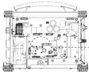
EQUIPMENT DESCRIPTION (FIG-1)
The PROGYS 220 FV CEL is a portable, ventilated Inverter welding station designed for welding the coated electrode (MMA) and the refractory electrode (TIG Lift) in direct current (DC).
The MMA process allows to weld all types of electrodes : rutile, basic, cast-iron and cellulosic.
The TIG process requires gas protection (Argon) and welds most metals except aluminum and its alloys.
It is protected for operation on generators (Power supply, 230V +-15%).
These products can be fitted with a remote control (ref. 045675) or a foot pedal (ref. 045682).
- Keypad
- Positive polarity connector
- Negative polarity connector
- Remote control connection
- ON / OFF switch
- Power supply cable
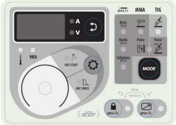
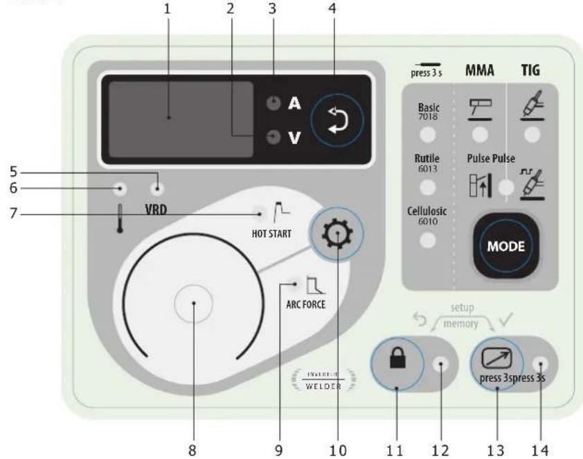
CONTROL BOARD (MMI) (FIG-2)
1- Display 12- Locked keypad indicator
2- Welding voltage display indicator 13- Remote control activation button
3- Welding current display indicator 14- Active remote control indicator
4- Selection button for displaying the welding voltage or welding current 15- Basic electrode indicator
5- Voltage Reducing Device (VRD) protection indicator
16- Rutile electrode indicator
6- Thermal protection indicator 17- Cellulosic electrode indicator
7- Hotstart range adjustment indicator 18- Refractory electrode mode indicator (TIG)
8- Main control wheel 19- Coated electrode mode indicator (MMA))
9- Arcforce range adjustment indicator
20- MMA and TIG mode indicator with pulse
10- Hotstart or Arcforce selection button
21- Mode selection button
11- Keypad lock button
POWER SUPPLY – START UP
- This equipment is supplied with a 16 A CEE7 / 7 plug and must be connected to a three-wire 230V (50-60 Hz) single-phase electrical installation with the earthed neutral. The PROGYS 220E FV CEL integrates a « Flexible Voltage » system. It has to be plugged on a power supply variable between 110V and 240V (50 – 60 Hz) WITH earth. The absorbed effective current (I1eff) is shown on the machine, for maximal using conditions. Check that the power supply and its protection (fuse and/or circuit-breaker) is compatible with the necessary current during use. For intensive use at 230Vrms and 110Vrms, disconnect the original plug and replace it with a 32A plug protected by a 32A circuit breaker. The welder must be installed so that the main plug is accessible.
- The power is switched on by rotating the On/Off switch to position I, conversely the power is switched off by rotating it to position O. Warning! Never disconnect the power supply while the machine is charging.
The device turns into protection mode if the supply voltage is over 265V for the single-phase products (the screen displays - - - -). Normal operation will resume when the voltage has returned to its nominal range.
CONNECTION ON A GENERATOR
The machine can work with generators as long as the auxiliary power matches these requirements :
- The voltage must be AC, always set as specified, and the peak voltage below 400V,
- The frequency must be between 50 and 60 Hz.
It is imperative to check these requirements as several generators generate high voltage peaks that can damage these machines.
USE WITH EXTENSION CABLES
All extension cables must have an adequate size and section, relative to the machine's voltage. Use an extension that complies with national safety regulations.
| Current input | Length - Extension selection | |
| < 45m < 100m | ||
| 230V 2.5 mm ^2 | ||
| 110V 2.5 mm ^2 4 mm ^2 | ||
ELECTRODE WELDING (MMA AND MMA VERTICAL UP)
CONNECTIONS AND RECOMMENDATIONS
- Connect the cables, electrode holder and earth clamp in the connectors,
- Respect the welding polarities and intensities indicated on the electrodes boxes,
- Remove the electrode from the electrode holder when the machin is not in use.
- Your machine is equipped with 3 specific functions to Inverters :
The Hot Start increases the current at the beginning of the welding.
- The Arc Force increases the current in order to avoid the sticking when electrode enters in melted metal.
- The Anti Sticking allows you to easily withdraw your electrode without damaging it in case of sticking.
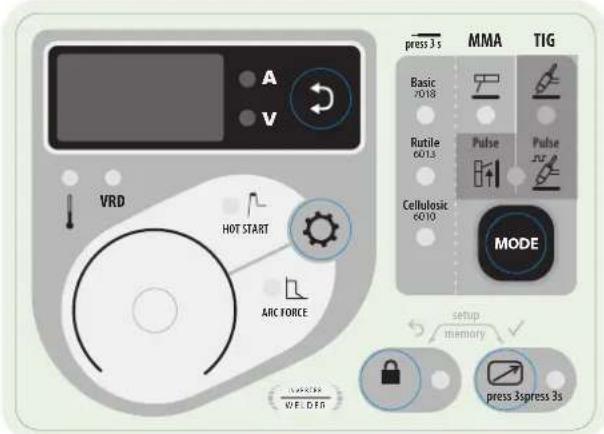
text_image
A V VRD HOT START AVIC FORCE press 3 s MMA TIG Basic 7018 Rutile 6013 Cellulosic 6010 Pulse Pulse JF MODE setup memory press 3spress 3s AVIC WE.DTGMMA
The grey areas are not useful for this mode.
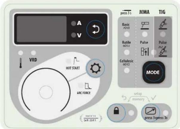
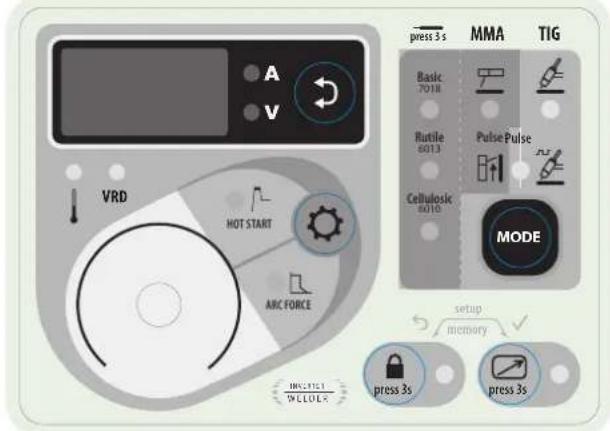
text_image
A V VRD HOT START ARC FORCE PRESS 3 s MMA TIG Basic V018 Rutile 6013 Cellulosic 6010 Pulse Pulse MODE setup memory press 3spress 3s WELDESMMA VERTICAL UP
The grey areas are not useful for this mode.
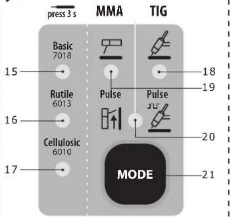
SELECTION MODE
MMA
Press button MODE several times until the LED lights up under the symbol
MMA PULSE
Press button MODE several times until the LEDs light up under the symbol and to the right of the symbol. The MMA vertical up mode adds a current pulse which makes vertical up welding easier.
MAIN SETTINGS
1. Selection of the type of coating
Select the electrode coating type by holding button MODE for more than 3 seconds until the LED lights up under the desired electrode type.
2. Setting the welding current
Adjust the welding current using the main knob according to the electrode diameter and the type of connection to be made. The current selected is indicated on the display.
3. Adjusting the Hotstart level
Press button ⚙️ until the LED lights up to the left of the symbol HOT START.
Adjust the Hotstart level using the main control wheel, which is expressed as a percentage of the current selected. The Hotstart level is indicated on the display.
4. Adjusting the Arcforce level
Press button ⚙ until the LED lights up to the left of the symbol ARC FORCE.
Adjust the Arcforce level using the main dial, which is indexed from -10 to +10. The lower the Arcforce level, the softer the arc, the higher the Arcforce level and the higher the welding overcurrent. The default value is 0.
WELDING INTENSITY SETTINGS
The following settings concern the intensity range that may be used depending on the electrode's type and diameter. These ranges are quite large as they depend on the application and the welding position.
| ∅ electrode (mm) | Rutile E6013 (A) | Basic E7018 (A) | Cellulosic E6010 (A) |
| 1.6 30-60 30-55 - | |||
| 2.0 50-70 50-80 - | |||
| 2.5 60-100 80-110 60-75 | |||
| 3.15 80-150 90-140 85-90 | |||
| 4.0 100-200 125-210 120-160 | |||
| 5 150-220 200-220 110-170 |
ARCFORCE SETTINGS
It is recommended to set the arc force in median position (0) to start the welding and adjust it according to the results and welding preferences. Note: the arcforce setting range is specific to the selected electrode type.
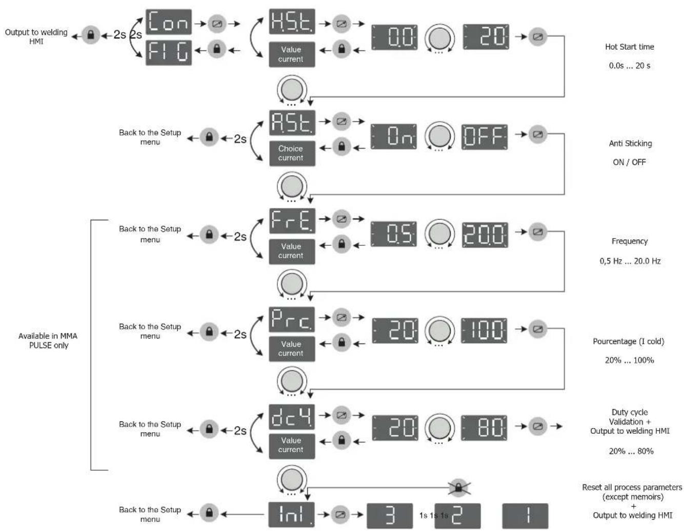
ADVANCED SETTINGS (MMA)
Refer to the chapter « Menu access » for more details regarding welding parameters.
The two MMA modes and come with the following additional settings:
H5. E.: Hotstart Time, duration of the extra current at arc strike, expressed in seconds.
RST: Antisticking, active (On), the current will stop after 2 consecutive seconds of short circuit, inactive (Off), the current will not stop, even in the event of long short circuit.
In MMA Pulse mode extra settings are available :
FrE: Frequency, determines the number of pulses per second (Hz).
Prc.: Percentage, determines the background/cold current expressed in percentage of the welding current.
dc4: Duty cycle, determines the duty cycle expressed as a percentage of the pulsation frequency.
TUNGSTEN ELECTRODE WELDING WITH INERT GAS (TIG AND TIG VERTICAL UP

CONNECTIONS AND RECOMMENDATIONS
TIG welding requires a torch as well as a gas bottle equipped with a regulator.
Connect the earth clamp to the positive connector (+).
Connect the torch's earth cable to the negative plug (-).
Connect the torch's gas hose to the regulator's output.
Ensure that the torch is equipped and ready to weld, and that the consumables (Vise grip, ceramic gas nozzle, collet and collet body) are not damaged.
text_image
A V VRD HOT START ABC FORCE PRESS WELDER press 3 s MMA TIG Basic 7018 Rutile 6013 Cellulosic 6010 Pulse Pulse MODE setup memory press 3s press 3sTIG
The grey areas are not useful for this mode.
text_image
press 3 s MMA TIG Basic 7018 Rutile 6013 Pulse Pulse Cellulosic 6010 MODE HV2011 W CLOL HOT START ARC FORCE setup memory press 3s press 3sTIG (TIG VERTICAL UP)
The grey areas are not useful for this mode.
SELECTION MODE
TIG
Press button MODE several times until the LED lights up under the symbol
TIG PULSE
Press button MODE several times until the LEDs light up under the symbol and to the left of the symbol
The pulsed TIG mode adds current pulsation to facilitate the welding of thin sheets while limiting temperature rise.
WELDING STETTINGS
- Welding intensity settings :
Adjust the welding current using the main knob according to the thickness and type of connection to be made. The current selected is indicated on the display.
ARC STRIKE / IGNITION :
LIFT start : Using the torch, make contact between the electrode and the metal piece, then slightly lift the electrode to start the arc.
WELD STOP / SWITCHING TO DOWNSLOPE :
To stop the weld, slightly lift the torch, the intensity will gradually reduce (downslope).
ASSISTANCE FOR SETTING UP AND SELECTING CONSUMABLES
| DC |  | Current (A) Electrode (mm) Shroud (mm) | Argon flow rate (L/min) | ||
| 0.3 - 3 mm 5 - 75 | 1 6.5 6 - 7 | ||||
| 2.4 - 6 mm 60 - 1 | 50 1.6 8 6 - 7 | ||||
| 4 - 8 mm 100 - 2 | 00 2 9.5 7 - 8 | ||||
| 6.8 - 8.8 mm 170 - | 250 | 2.4 | 11 | 8 - 9 | |
ELECTRODE GRINDING
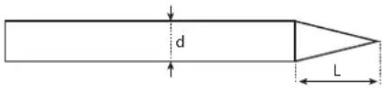
text_image
d LL = 3 x d for a low current.
L = 3 x d for a high current
ADVANCED SETTINGS (TIG)
Refer to the chapter « Menu access » for more details regarding welding parameters.
The two TIG modes = and =r= come with the following additional settings :
- : I_Start, determines the level of the starting current expressed as a percentage of the welding current.
UPS : UpSlope, duration of the ramp up (if I_Start < Welding) or ramp down (if I_Start > Welding) of the welding current expressed in seconds.
do5: DownSlope, duration of the welding current decreasing expressed in seconds.
In TIG Pulse mode Pulse sur , 3 extra settings are available :
FrE: Frequency, determines the number of pulses per second (Hz).
Prc: Percentage, determines the background/cold current expressed in percentage of the welding current.
dc4: Duty cycle, determines the duty cycle expressed as a percentage of the pulsation frequency.
DISPLAY CURRENT/VOLTAGE DURING WELDING
During welding, the machine measures and displays the welding current and voltage. After the weld, the average current and voltage values are displayed during 30 seconds, as soon as a knob or a button is pressed, the welding parameters are displayed.
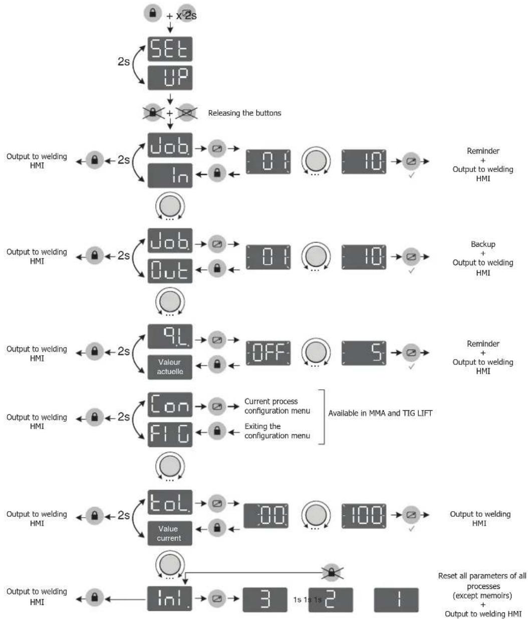
SAVE AND RECALL WELDING SETTINGS
The current settings are automatically saved and will load next time the machine is used.
In addition to the current settings it is possible to save and recall configurations
There are 10 memory slots per mode.
The memory settings apply to :
- The main parameter (process, current setpoint)
- The secondary parameters (Hotstart, Arcforce, Upslope, etc.)
Save a configuration :

and

for 2 seconds.


appears, release the buttons.
- Turn one of the two knobs to display Job In. Confirm by pressing button
- The display flashes to indicate a memory slot (01 to 10).
- Turn the knob to select the memory slot in which the desired settings will be saved. Validate by pressing the button

Recall existing settings:
- Press and hold the buttons and for 3 seconds. appears, release the buttons.
- Turn the control wheel to display . Validate by pressing the button .
- The display flashes to indicate a memory slot (01 to 10).
- Turn the control wheel to select the memory slot containing the settings to be recalled. Validate by pressing the button
QUICK LOAD « q.L. »
The Quickload is a JOB reminder mode outside welding. This mode is possible in MMA.
JOB reminders are made by briefly pressing and releasing the SWITCH of the remote control via a dedicated remote control.
E.g.: if JOB 2, 5, 7 and 10 have been created and the user has entered the number 7, then the recalled JOBs will be 2, 5 and 7.
When the mode is activated, the first JOB is recalled and displayed at the HMI (in the example: JOB 2 and display «J.02»).
If unlocked, the HMI behaves with the specificities:
- the HMI displays «J.XX» continuously as well as the parameters (welding process, Pulse, electrode type,...).
- The cycle is accessible and modifiable (the JOB is out of adjustment (*)),
- The menus are accessible and can be modified. Ex :
- JOB 5, out of adjustment, SAVE IN / JOB 5, the JOB is overwritten with the new parameters and taken into account.
- JOB 5, out of adjustment, SAVE IN / JOB non-existent, it will be taken into account in the current q.L. if and only if this new JOB X is lower than the number of the JOB entered.
- The JOB reminder is inactive when navigating through the welding cycle or one of the two menus.
(*) A JOB is disturbed by HMI action (welding parameter, JOB recall...), welding is allowed with the new settings. If a JOB recall is performed, then the first JOB in the series is recalled.
VOLTAGE REDUCING DEVICE (VRD)
The voltage reducing device (or VRD) reduces the assigned no-load voltage to a level not exceeding 35V when the resistance of the external welding circuit exceeds 200Ω. The reaction time is less than 300ms.
By default, the voltage reducer device is disabled. In order to activate it, the user must open the product and follow the following procedure:
- Switch off and disconnect the product from the network
- Set the switches as below:
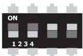
text_image
ON 1 2 3 4| 1 2 3 4 VRD | ||||
| 0 0 | 1 1 NO (by default) | |||
| 0 0 | 0 0 YES | |||
natural_image
Technical line drawing of a mechanical or electronic device with no visible text, numbers, or symbols.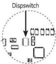
flowchart
graph TD
    A["Input Module"] --> B["Splitter"]
    B --> C["Output Module 1"]
    B --> D["Output Module 2"]
    B --> E["Output Module 3"]
    B --> F["Output Module 4"]
    style A fill:#f9f,stroke:#333
    style B fill:#ccf,stroke:#333
    style C fill:#cfc,stroke:#333
    style D fill:#fcc,stroke:#333
    style E fill:#cff,stroke:#333
    style F fill:#ffc,stroke:#333
- When the product is switched on, the device is active and the «VRD» LED on the keypad lights up.
REMOTE CONTROL
The remote control operates in TIG mode and in MMA.
text_image
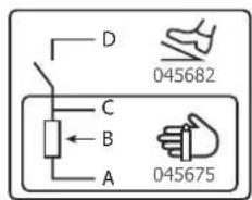
D 045682 C B A 045675ref. 045699 External view Electric diagram according to remote control type.
Connection
1- Plug the remote control into the connection at the back of the machine.
2- The machine will detect automatically the remote control and open a selection menu:

Foot pedal selection.
Remote control with potentiometer selection.
3- The selection of the type of remote control is made using the wheel, the validation is made using the button.
4- The LED (FIG-2, n°14) switches on.
5- It is possible to activate / deactivate the remote control without having to physically unplug the remote control. Press the button ☐, for 3 seconds, the LED (FIG-2, n°14) indicates the state of the remote control (LED on = remote control on).
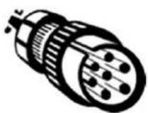
Connection
The TIG 300 DC is equipped with a female socket for a remote control.
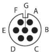
The specific 7 pin male plug (option ref.045699) enables connection to the different types of manual remote control or foot pedal. For the cabling layout, please see the diagram below.
| REMOTE CONTROL TYPE Wire description Pin | |||
| Foot pedal Manual remote control | VCC A | ||
| Cursor B | |||
| Common/Earth C | |||
| Switch D | |||
Operating :
• Manual remote control (option ref. 045675)
The remote control enables the variation of current from 50% to 100% of the set intensity. In this configuration, all modes and functions of the machine are accessible and can be set.
• Pedal (option ref. 045682):
The pedal control enables variation of current from 10% to 100% of the set intensity.
In TIG LIFT mode, the arc strike, upslope and downslope are not automatic, and are controlled by the User with the foot pedal.
COOLING FAN
To minimise sound and dust aspiration, the station integrates a controlled fan system. The fan's rotation speed depends on the temperature and the machine's settings.
LOCKING CONTROLS
That feature can lock the knobs and keypad to prevent accidental changes in the settings.
Operation :
Press the button 🔒 for 3 seconds, the display shows Loc. and goes back to current display. The LED (FIG-2, n°12) switches on. No button is enabled, the secondary knob is disabled, the main knob can adjust the value at +/- of the percentage, defined by the «tolerance» setting tol. (see chapter «Access to menus»).
To unlock the commands, press the button for 3 seconds, the display shows Un Loc then goes back to current display. The LED (FIG-2, n°12) switches off.
ACCESS TO MENUS
flowchart
graph TD
    A["SET-up"] --> B["Releasing the buttons"]
    B --> C["Output to welding HMI"]
    C --> D["Job/In/Out"]
    D --> E["0:1/... 10:1/√"]
    E --> F["Reminder + Output to welding HMI"]
    G["Output to welding HMI"] --> H["Job/Out"]
    H --> I["0:1/... 10:1/√"]
    I --> J["Backup + Output to welding HMI"]
    K["Output to welding HMI"] --> L["9L Valeur actuelle"]
    L --> M["OFF... 5:1/√"]
    M --> N["Reminder + Output to welding HMI"]
    O["Output to welding HMI"] --> P["Con FI G"]
    P --> Q["Current process configuration menu\nExiting the configuration menu\nAvailable in MMA and TIG LIFT"]
    Q --> R["Value current"]
    R --> S["100:100:100:100:100:100:100:100:100:100:100:100:100:100:100:100:100:100:100:100:100:100:100:100:100:100"]
    T["Input"] --> U["Inl."]
    U --> V["3 1s 1s 2 1"]
    V --> W["Reset all parameters of all processes (except memoirs) + Output to welding HMI"]
Advanced MMA process menu
flowchart
graph TD
    A["Output to welding HMI"] --> B["Con 2s"]
    B --> C["FIG 2s"]
    C --> D["HSI. Value current"]
    D --> E["0.0"]
    E --> F["20"]
    F --> G["Hot Start time 0.0s ... 20 s"]
    H["Back to the Setup menu"] --> I["AST. Choice current"]
    I --> J["On"]
    J --> K["OFF"]
    K --> L["Anti Sticking ON / OFF"]
    M["Available in MMA PULSE only"] --> N["FR.E. Value current"]
    N --> O["0.5"]
    O --> P["200"]
    P --> Q["Frequency 0.5 Hz ... 20.0 Hz"]
    R["Back to the Setup menu"] --> S["Prc. Value current"]
    S --> T["20"]
    T --> U["100"]
    U --> V["Pourcentage (I cold) 20% ... 100%"]
    W["Back to the Setup menu"] --> X["dC4. Value current"]
    X --> Y["20"]
    Y --> Z["80"]
    Z --> AA["Duty cycle Validation + Output to welding HMI 20% ... 80%"]
    AB["Back to the Setup menu"] --> AC["Ini."]
    AC --> AD["3"]
    AD --> AE["1s 1s 1s 2"]
    AE --> AF["Reset all process parameters (except memoirs) + Output to welding HMI"]
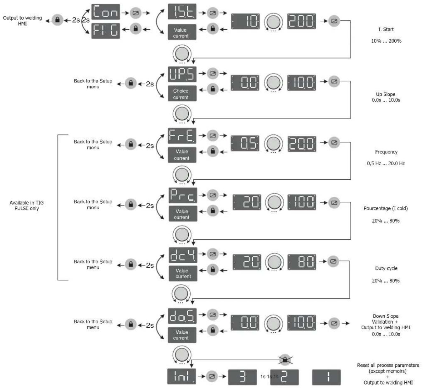
Advanced TIG process menu
flowchart
graph TD
    A["Output to welding HMI"] --> B["Con 2s"]
    B --> C["FI G 2s"]
    C --> D["15t. Value current 10 200"]
    D --> E["I. Start 10% ... 200%"]
    F["Back to the Setup menu"] --> G["2s"]
    G --> H["UPS. Choice current 0.0 10.0"]
    H --> I["Up Slope 0.0s ... 10.0s"]
    J["Available in TIG PULSE only"] --> K["Back to the Setup menu"]
    K --> L["2s"]
    L --> M["FrE. Value current 0.5 200"]
    M --> N["Frequency 0.5 Hz ... 20.0 Hz"]
    O["Back to the Setup menu"] --> P["2s"]
    P --> Q["Prc. Value current 20 100"]
    Q --> R["Pourcentage (1 cold) 20% ... 80%"]
    S["Back to the Setup menu"] --> T["2s"]
    T --> U["dC4. Value current 20 80"]
    U --> V["Duty cycle 20% ... 80%"]
    W["Back to the Setup menu"] --> X["2s"]
    X --> Y["dQ5. Value current 0.0 10.0"]
    Y --> Z["Down Slope Validation + Output to welding HMI 0.0s ... 10.0s"]
    AA["Inl. Reset all process parameters (except memoirs) + Output to welding HMI"] --> AB["3 1s 1s 2"]
    AC["Reset all process parameters (except memoirs) + Output to welding HMI"] --> AD["1"]
TROUBLESHOOTING
This device integrates a default management system. In the event of a default, error messages may be displayed.
| Error code Meaning CAUSES SOLUTIONS | |||
 | Thermal protection | "Exceeding the duty cycleAmbient temperature above 40°CBlocked air inlets" | "Wait for the indicator to turn off before resuming welding operations.Observe the operating factor and ensure good ventilation" |
 | Mains overvoltage fault Mains | voltage outside maximum tolerance | Have the sensors connection checked by a qualified person. |
 | Mains undervoltage fault Mains | voltage outside minimum tolerance | Have your electrical installation checked by a qualified person. The mains voltage must be between 95Vrms and 265Vrms. |
 | Fan fault The fan is not running | at the right speed. | Check for foreign bodies that could slow down the fan, check the correct wiring, replace the fan |
| «HE1» | Power relay control fault The | power relay could not be closed | Have the wiring of the relay control system checked by qualified personnel |
| «HE2» | Settings memorisation fault The EEPROM memory is defective Contact your reseller | ||
| «HE3» | No temperature information | The temperature sensors are disconnected | Have the sensor wiring checked by qualified staff |
| «HE4» | Defective keyboard buttons | One or more buttons on the keyboard are permanently short-circuited | Replace the keyboard |
| «SE» | Software Error Communication problemn Contact your reseller | ||
All operations requiring the removal of the machine's cover and checking the electrical systems must be done by a qualified technician.
WARRANTY
The warranty covers faulty workmanship for 2 years from the date of purchase (parts and labour).
The warranty does not cover:
- Transit damage.
- Normal wear of parts (eg. : cables, clamps, etc..).
- Damages due to misuse (power supply error, dropping of equipment, disassembling).
- Environment related failures (pollution, rust, dust).
In case of failure, return the unit to your distributor together with: - The proof of purchase (receipt etc ...)
- A description of the fault reported.

text_image
Dispswitchnatural_image
Technical line drawing of a mechanical or electronic device with no visible text, numbers, or symbols.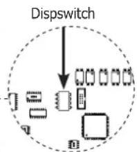
flowchart
graph TD
    A["Input"] --> B{Dispswitch}
    B --> C["Process Unit 1"]
    B --> D["Process Unit 2"]
    B --> E["Process Unit 3"]
    B --> F["Process Unit 4"]
    B --> G["Output"]
    style B fill:#f9f,stroke:#333,stroke-width:2px
text_image
DispswitchWAARSCHUWING - VEILIGHEIDSINSTRUCTIES
ALGEMENE INSTRUCTIES

INSTALLATIE VAN HET APPARAAT
INTERFACE HUMANE MACHINE (IHM) (FIG-2)
text_image
Dispswitchflowchart
graph TD
    A["Uitgang naar las-HMI"] --> B["2s"]
    B --> C["Con"]
    B --> D["FIG"]
    C --> E["2s"]
    D --> E
    E --> F["HST"]
    E --> G["Waarde huidig"]
    F --> H["00:00:20:00:00:00:00:00:00:00:00:00:00:00:00:00:00:00:00:00:00:00:00:00:00:00:00:00:00:00:00:00:00:00:00:00:01"]
    G --> I["..."]
    I --> J["..."]
    J --> K["..."]
    K --> L["..."]
    L --> M["RST"]
    L --> N["Keuze huidig"]
    M --> O["On:On:Off:Off:Off:Off:Off:Off:Off:Off:Off:Off:Off:Off:Off:Off:Off:Off:Off:Off:Off:Off:Off:Off:Off:Off:Off:Off:Off:Off:Off:Off:Off:Off:Off:Off:Off:Off:Off:Off:Off:Off:Off:Off:Off:Off:Off:Off:Off:Off:Off:Off:FF"]
    N --> P["..."]
    P --> Q["..."]
    Q --> R["..."]
    R --> S["FRE"]
    R --> T["Waarde huidig"]
    S --> U["2s"]
    T --> V["2s"]
    U --> W["2s"]
    V --> X["2s"]
    W --> Y["2s"]
    X --> Z["2s"]
    Y --> AA["2s"]
    Z --> AB["..."]
    AA --> AC["Prc"]
    AA --> AD["Waarde huidig"]
    AC --> AE["2s"]
    AD --> AF["2s"]
    AE --> AG["2s"]
    AF --> AH["2s"]
    AG --> AI["2s"]
    AH --> AJ["2s"]
    AI --> AK["dc4"]
    AI --> AL["Waarde huidig"]
    AK --> AM["2s"]
    AL --> AN["2s"]
    AM --> AO["..."]
    AN --> AP["..."]
    AO --> AQ["..."]
    AP --> AR["..."]
    AQ --> AS["..."]
    AR --> AT["Inl."]
    AS --> AU["3s 1s 1s 2s 1s 1s 1s 1s 1s 1s 1s 1s 1s 1s 1s 1s 1s 1s 1s 1s 1s 1s 1s 1s 1s 1s 1s 1s 1s 1s 1s 1s 1s 1s 1s 1s 1s 1S"]
text_image
Dispswitchtext_image
Dispswitch*The duty cycles are measured according to standard EN60974-1 à 40°C and on a 10 min cycle.
While under intensive use (> to duty cycle) the thermal protection can turn on, in that case, the arc switches off and the indicator switches on
Keep the machine's power supply on to enable cooling until thermal protection cancellation.
The welding power source describes an external drooping characteristic.
text_image
Technical diagram of a portable electronic device with labeled components including control panel, buttons, and ventilation grilles.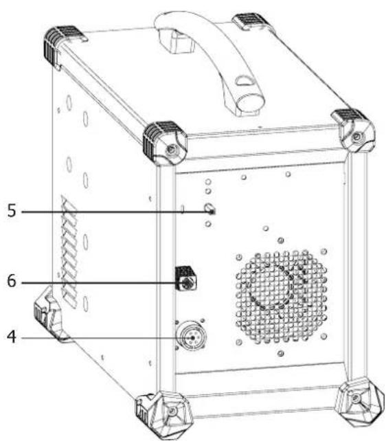
text_image
5 6 4INTERFACE / INTERFACE / SCHNITTSTELLE / INTERFAZ / ИНТЕРФЕЙС / INTERFACE / INTERFACCIA / INTERFEJS
FIG. 2
text_image
1 2 3 4 press 3 s MMA TIG Basic 7018 Rutile 6013 Pulse Pulse Cellulosic 6010 MODE 5 6 7 VRD HOT START ARC FORCE setup memory 10 11 12 13 14 WELDER press 3spress 3s
text_image
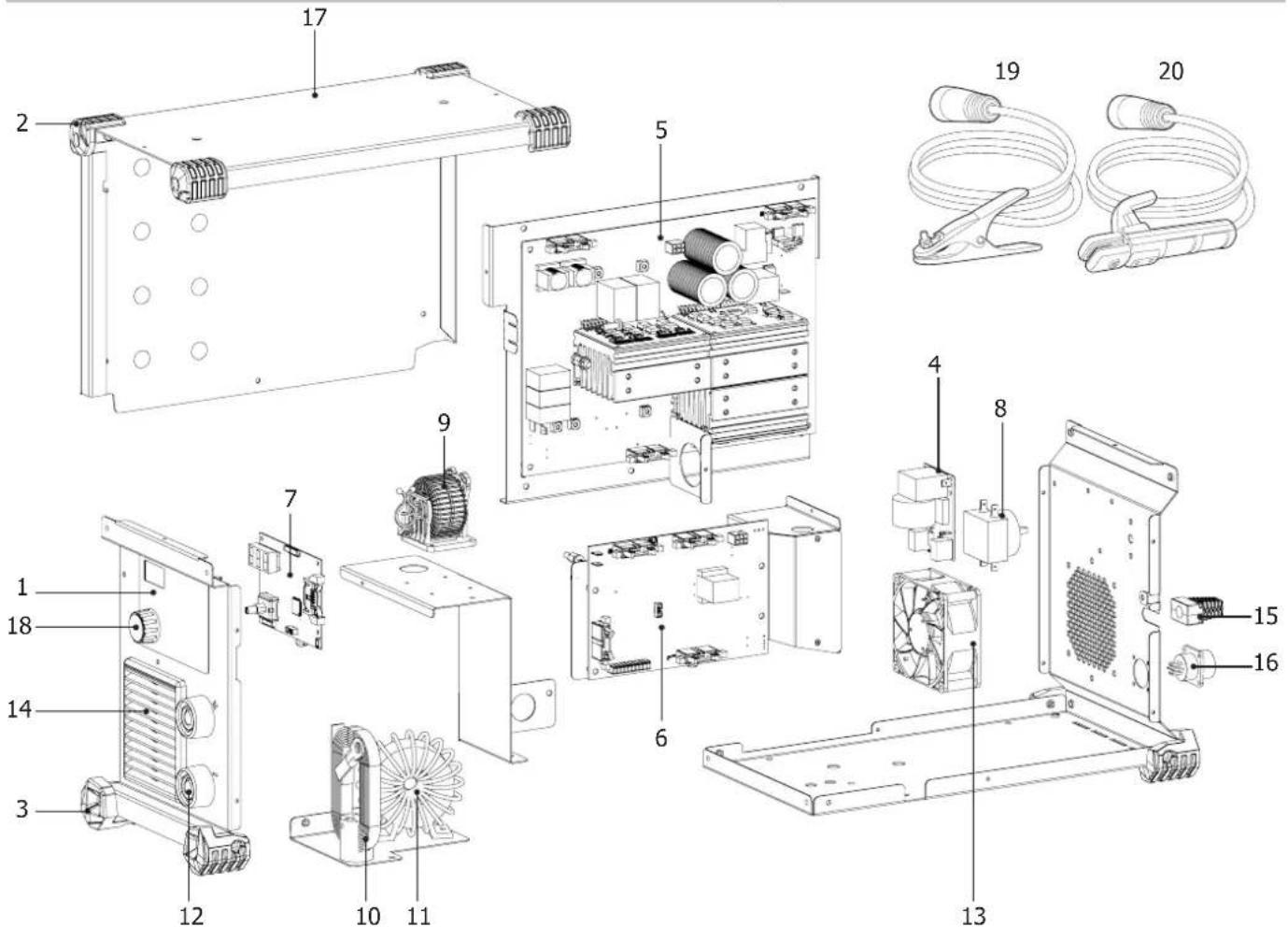
press 3 s MMA TIG Basic 7018 Rutile 6013 Cellulosic 6010 15 16 17 Pulse Pulse 20 MODE 21 18 19PIÈCES DE RECHANGE / SPARE PARTS / ERSATZTEILE / PIEZAS DE REPUESTO / ЗАПАСНЫЕ ЧАСТИ / RESERVE ONDERDELEN / PEZZI DI RICAMBIO / CZĘŚCI ZAMIENNE
text_image
Exploded view diagram of an electronic device with numbered components for identification| Désignation | ||
| 1 | Clavier / Keypad / Bedienfeld / Teclado / Панель управления / Bedieningspaneel / Tastiera / Klawiatura | 51975 |
| 2 | Patin supérieur (1point) / Upper skid (1 point) / oberer Gummifuß (1 Punkt) / Soporte superior (1punto) / Верхний башмак (1точка) / Rubberen blokje boven (1 punt) / Patina superiore (1 punto) / Stopka górna (1 punkt) | 56163 |
| 3 | Patin inférieur (3points) / Lower skid (3 points) / unterer Gummifuß (3 Punkte) / Suporte inferior (3puntos) / Нижний башмак (3точки) / Rubberen blokje onder (3 punten) / Patina inferiore (3 punti) / Stopka niższa (3 punkty) | 56120 |
| 4 | Carte CEM / CEM board / EMV-Platine / Tarjeta CEM / Плата Электромагнитной совместимости / Printplaat / Carta CEM / Karta EMC | 97771C |
| 5 | Carte de Puissance / Power Chart / Leistungsplatine / Tarjeta de potencia / Плата Мощности / Vermogens printplaat / Carta di potenza / Karta mocy | 97756C |
| 6 | Carte de Contrôle / Control Chart / Steuerplatine / Tarjeta de control / Плата Управления / Controle-kaart / Carta di controllo / Karta kontrolna | 97758C |
| 7 | Carte d'affichage / Display circuit board / Anzeigeplatine / Tarjeta de vídeo / Плата индикации / Videokaart / Scheda video / Karta graficzna | 97757C |
| 8 | Commutateur Marche/Arrêt / On/off switch / Schalter Start/Stop / Conmutador Encendido/Apagado / Переключатель ВКЛ/ВЫКЛ / Schakelaar Aan/Uit / Commutatore Avvio/ Arresto / Przełącznik ON / OFF | 51075 |
| 9 | Self PFC / Auto PFC / Drossel PFC / Inductancia PFC / Дроссель PFC / Inductie PFC / Self PFC / Self PFC | 63691 |
| 10 | Self de sortie / Output capacitor / Ausgangsdrossel / Inductancia de salida / Выходной дроссель / Uitgaande smoorklep / Self di uscita / Dławik wyjściowy | 96141 |
| 11 | Transformateur de puissance torque / Toroidal power transformer / Ringkernetztransformator / Transformador de potencia toroidal / Тороидальный трансформатор мощности / Ringkerntransformator / Trasformatore di potenza torica / Toroidalny transformator mocy | 63802 |
| 12 | Douilles Texas 50 femelles / 50 female dinse sockets / Texas 50 Buchsen / Conector Texas 50 hembra / Гнезда Texas 50 / Texas vrouwelijke aansluiting 50x / Connettori Texas 50 femmine / Gniazda żcńskie TEXAS 50 | 51468 |
| 13 | Ventilateur PWM / PWM fan / PWM Lüfter / Ventilador PWM / Ventilator PWM / Вентилятор PWM / Ventilatore PWM / Wentylator PWM | 50999 |
| 14 | Grille plastique 92x92 / Plastic grid 92x92 / Plastikgitter 92x92 / Rejilla de plástico 92x92 / Пластмассовая решетка 92x92 / Plastic rooster 92x92 / Griglia plastica 92x92 / Kratka z tworzywa sztucznego 92x92 | 51011 |
| 15 | Cordon secteur 3x2,5mm ^2 / Power cord 3x2.5mm ^2 / Netzleitung 3x2,5mm ^2 / Cable de conexión eléctrica 3x2,5mm ^2 / Сетевой шнур 3x2,5mm ^2 / Netsnoer 3x2,5mm ^2 / Cavo corrente 3x2,5mm ^2 / Główny kabel 3x2,5mm ^2 | 21464 |
| 16 | Faisceau connectique commande à distance / Remote control connection cable / Fernregelunganschlusskabel / Conector cableado de control a distancia / Подключение дистанционного управления / Aansluiting afstandsbediening / Fascio connessioni comando a distanza / Wiązka złączeń zdalnego sterowania | 71513 |
| 17 | Poignée / Handle / Handgriff / Mango / Ручка / Handvat / Impugnatura / Uchwyt | 56048 |
| 18 | Bouton potentiomètre / Potentiometer button / Potentiometerknopf / Botón de potenciómetro / Кнопка потенциометра / Draaiknop / Tasto potenziometro / Pokrętło potencjometru | 73016 |
| 19 | Câble de masse / Earth cable / Massekabel / Cable de masa / Кабель массы / Massakabel / Cavo di massa / Kabel uziemienia | 043794 |
| 20 | Porte-électrode assemblé / Assembled electrode holder / Montierter Elektrodenhalter / Portaelectrodos ensamblados / Электрододержатель в сборе / Geassembleerde elektrode-houder / Porta elettrodo assemblato / Zmontowany uchwyt elektrody | 043862 |
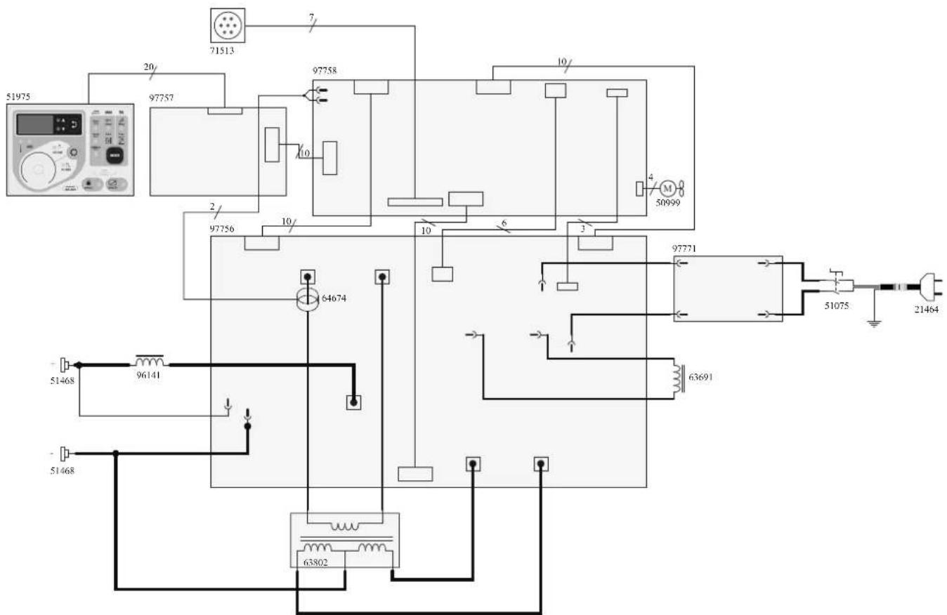
SCHÉMA ÉLECTRIQUE / CIRCUIT DIAGRAM /SCHALTPLAN/ DIAGRAMA ELECTRICO / ЭЛЕКТРИЧЕСКАЯ СХЕМА / ELEKTRISCHE SCHEMA / SCEMA ELETTRICO / SCHEMAT ELEKTRYCZNY
text_image
51975 20 71513 97757 97758 10 10/1 97756 2 10/ 64674 3 97771 51075 21464 51468 96141 63691 51468 63802ICÔNES / SYMBOLS / ZEICHENERKLÄRUNG / SÍMBOLOS / СИМВОЛЫ / PICTOGRAMMEN / ICONA / IKONY
 | - Attention ! Lire le manuel d'instruction avant utilisation. - Caution ! Read the user manual. - Achtung! Lesen Sie die Betriebsanleitung. - Cuidado, leer las instrucciones de utilización. - Внимание ! Читайте инструкцию по использованию. - Let op! Lees voorzichtig de gebruiksaanwijzing. - Attenzione! Leggere il manuale d'istruzioni prima dell'uso. - Uwaga! Przed użyciem należy dokladnie zapoznać się z instrukcją obsługi. |
| - Convertisseur monophasé - Single phase inverter, converter-rectifier - Einphasiger statischer Frequenzumformer/ Trafo/ Gleichrichter - Convertidor monofásico transformador-rectificador - Однофазный преобразователь, трансформатор-выпрямитель - Enkel fase omvormer - Trasformatore monofase - Jednofazowy transformator-prostownik. | |
| EN60974-1EN60974 - 10Class A | - La source de courant de soudage est conforme aux normes EN60974-1/-10 et de classe A. - This welding machine is compliant with standard EN60974-1/-10 of class A. - Die Stromquelle entspricht der Norm EN60974-1/-10. Gerät Klasse A. - El aparato es conforme a las normas EN60974-1/-10 y de classe A. - Источник сварочного тока отвечает нормам EN60974-1/-10 и относится к классу A. - De lasstroomvoorziening is conform aan de EN60974-1/-10 en klasse A norm. - La fonte di corrente di saldatura è conforme alle norme EN60974-1/-10 e di classe A. - Žródło prądu spawania, zgodne jest z normami EN60974-1/-10 i klasą A. |
 | - Soudage à l'électrode enrobée (MMA - Manual Metal Arc) - Electrode welding (MMA - Manual Metal Arc) - Schweißen mit umhüller Elektrode (E-Handschweißen) - Soldadura con electrodos refractarios (TIG - Tungsten Inert Gas) - Ручная дуговая сварка (MMA - Manual Metal Arc) - Booglassen met beklede elektrode (MMA - Manual Metal Arc) - Saldatura ad elettrodo rivestito (MMA - Manual Metal Arc) - Spawanie elektrodami otulonymi (MMA - Manual Metal Arc) |
 | Soudage TIG (Tungsten Inert Gaz)TIG - welding (Tungsten Inert Gas) - Schweißen mit Wolfram Elektrode (Wolfram Edelgas) - Soldadura TIG (Tungsten Inert Gaz) - Сварка TIG (Tungsten Inert Gaz) - Saldatura TIG (Tungsten Inert Gaz) - TIG lassen (Tungsten Inert Gaz) - Spawanie TIG (Wolfram Gazu Obojętnego) |
| [WWKC] | - Convient au soudage dans un environnement avec risque accru de choc électrique. La source de courant elle-même ne doit toutefois pas être placée dans de tels locaux. - Adapted for welding in environments with increased risk of electrical shock. However, the welding machine should not be placed in such places. - Geeignet für Schweißarbeiten im Bereich mit erhöhten elektrischen Risiken. Trotzdem sollte die Schweißquelle nicht unbedingt in solchen Bereichen betrieben werden. - Adaptado a la soldadura en un entorno que comprende riesgos de choque eléctrico. La fuente de corriente ella misma no debe estar situada dentro de tal locales. - Подходит для сварки в среде с повышенной опасностью удара электрическим током. Тем не менее не следует ставить источник тока в такие помещения. - Geschikt voor het lassen in een ruimte met verhoogd risico op elektrische schokken. De voedingsbron zelf moet echter niet in dergelijke ruimte worden geplaatst. - É consigliato per la saldatura in un ambiente con grandi rischi di scosse elettriche. La fonte di corrente non deve essere localizzata in tale posto. - Nadaje się do spawania w środowisku o zwiększonym ryzyku porażenia prądem. Samo źródło prądu nie może jednak być umieszczzone w tego typu pomieszczeniach. |
 | Courant de soudage continu - Welding direct current - Gleichschweisstrom - La corriente de soldadura es continua - Сварка на постоянном токе - Continue lasstroom -Corrente di saldatura continua - Staly prąd spawania |
| Uo | Tension assignée à vide - Rated no-load voltage - Leerlaufspannung - Tensión asignada de vacío - Напряжение холостого хода - Nullastspanning - Tensione nominale a vuoto - Znamionowe napięcie próżniowe |
 | X : Facteur de marche à ...% - X : duty cycle at ...% - X : Einschaltdauer ...% - X : Factor de funcionamiento de ...% - X : Продолжительность включения ...% - X: Inschakelduur bij ...% - X : Ciclo di lavoro a ...% - X : Cykl pracy wynosi....% |
| I2 | I2 : courant de soudage conventionnel correspondant - I2 : corresponding conventional welding current - I2 : entsprechender Schweißstrom - I2 : Corrientes correspondientes - I2 : Соответствующий условный сварочный ток - I2 : overeenkomstige conventionele lasstroom - I2 : corrente di saldatura convenzionale corrispondente - Odpowiedni prąd spawania konwencjonalnego |
 | - Ampes - Ampere - Amperio - Amper - Ampère - Amper - Ampery |
| U2 | U2 : Tensions conventionnelles en charges correspondantes - U2 : conventional voltages in corresponding load - U2 : entsprechende Arbeitsspannung - U2 : Tensiones convencionales en carga - U2 : Соответствующие условные напряжения под нагрузкой - U2 : conventionele spanning in corresponderende belasting - U2 : Tensioni convenzionali in cariche corrispondenti - Napięcia konwencjonalne przy odpowiednich obciążenich |
 | - Volt - Voltios - Вольт - Volt - Volt - Volt - Volt |
| Hz Hertz - Hertz | - Hertz - Hertz - Hertz - Герц - Hertz - Hertz - Herc |
150-1  | - Alimentation électrique monophasée 50 ou 60Hz - Single phase power supply 50 or 60Hz - Einphasige Netzversorgung mit 50 oder 60Hz - Alimentación eléctrica monofásica 50 o 60 Hz - Однофазное напряжение 50 или 60Гц - Enkel fase elektrische voeding 50Hz of 60Hz - Alimentazione elettrica monofase 50 o 60Hz - Zasilanie jednofazowe 50 lub 60Hz |
| U1 | Tension assignée d'alimentation - rated supply voltage - Netzspannung - Tensión de la red - Напряжение сети - Nominale voedingsspanning - Tensione nominale d'alimentazione - Napięcie znamionowe zasilania |
| I1max | - Courant d'alimentation assigné maximal (valeur efficace) - Rated maximum supply current (effective value) - Maximaler Versorgungsstrom (Effektivwert) - Corriente maxima de alimentacion de la red - Максимальный сетевой ток (эффективная мощность) - Maximale nominale voedingsstroom (effectieve waarde) - Corrente d'alimentazione nominale massima (valore effettivo) - Maksymalny prąd znamionowy zasilania (wartość skuteczna) |
| I1eff | - Courant d'alimentation effectif maximal - Maximum effective supply current - Maximaler tatsächlicher Versorgungsstrom - Corriente de alimentacion efectiva maxima - Максимальный эффективный сетевой ток - Maximale effectieve voedingsstroom - Corrente di alimentazione massima effettiva - Maksymalny skuteczny prąd zasilania |
 | - Marque de conformité EAC (Communauté économique Eurasienne) - Conformity mark EAC (Eurasian Economic Commission) - EAC-Konformitätszeichen (Eurasische Wirtschaftsgemeinschaft) - Marca de conformidad EAC (Comunidad económica euroasiática) - Маркировка соответствия EAC (Евразийское экономическое сообщество) - EAC (Euraziatische Economische Gemeenschap) merkteken van overeenstemming. - Marca di conformità EAC (Comunità Economica Eurasiatica) - Znak zgodności EAC (Euroazjatyckiej wspólnoty Gospodarczej) |
 | - Ce matériel fait l'objet d'une collecte sélective selon la directive européenne 2012/19/UE. Ne pas jeter dans une poubelle domestique !- This hardware is subject to waste collection according to the European directives 2002/96/UE. Do not throw out in a domestic bin !- Für die Entsorgung Ihres Gerätes gelten besondere Bestimmungen (sondermüll) gemäß europäische Bestimmung 2012/19/EU. Es darf nicht mit dem Hausmüll entsorgt werden.- Este material sujeto a la recogida por separado de acuerdo con la Directiva de la UE 2012/19 / UE. No tire en un cubo de basura doméstia!- Это оборудование подлежит переработке согласно директиве Евросююза 2012/19/UE. Не выбрасывать в общий мусоросборник!- Afzonderlijke inzameling vereist volgens de Europese richtlijn 2012/19/UE. Gooi het apparaat niet bij het huishoudelijk afval !- Questo dispositivo è oggetto di raccolta differenziata secondo la direttiva europea 2012/19/UE. Non gettare nei rifiuti domestici !- Urządzenie to podlega selektywnej zbiorce odpadów zgodnie z dyrektywą UE 2012/19/UE. Nie wyrzucać do zwykłego kosza! |
 | - Appareil conforme aux directives européennes. La déclaration de conformité est disponible sur notre site internet. - The device complies with European Directive. The certificate of compliance is available on our website. - Gerät entspricht europäischen Richtlinien. Die Konformitätserklärung finden Sie auf unsere Webseite. - El aparato está conforme a las normas europeas. La declaración de conformidad está disponible en nuestra página Web. - Устройство соответствует европейским нормам, Декларация соответствия есть на нашем сайте. - Het toestel is in overeenstemming met de Europese richtlijnen. De conformiteitsverklaring is te vinden op onze internetsite. - Dispositivo in conformità con le norme europee. La dichiarazione di conformità è disponibile sul nostro sito internet. - Urządzenie spełnia wymagania dyrektyw europejskich. Deklaracja zgodności dostępna jest na naszej stronie internetowej. |
 | - Matériel conforme aux normes Morcalines. La déclaration C_ (CMIM) de conformité est disponible sur notre site (voir à la page de couverture).- Equipment in conformity with Moroccan standards. The declaration C_ (CMIM) of conformity is available on our website (see cover page).- Das Gerät entspricht die marokkanischen Standards. Die Konformitätserklärung C_ (CMIM) ist auf unserer Webseite verfügbar (siehe Titelseite).- Equipamiento conforme a las normas marroquées. La declaración de conformidad C_ (CMIM) está disponible en nuestra página web (ver página de portada).- Товар соответствует нормам Марокко, Декларация C_ (CMIM) доступна для скачивания на нашем сайте (см на титульной странице).- Dit materiaal voldoet aan de Marokkaanse normen. De verklaring C_ (CMIM) van overeenstemming is beschikbaar op onze internet site (vermeld op de omslag).- Materiale conforme alle normative marocchine. La dichiarazione C_ (CMIM) di conformità è disponibile sul nostro sito (vedi scheda del prodotto)- Urządzenie zgodne ze standardami marokarskimli. Deklaracja zgodności C_ (CMIM) jest dostępna na naszej stronie internetowej (patrz strona tytułowa). |
 | - Matériel conforme aux exigences britanniques. La déclaration de conformité britannique est disponible sur notre site (voir à la page de couverture).- Equipment in compliance with British requirements. The British Declaration of Conformity is available on our website (see home page).- Das Gerät entspricht den britischen Richtlinien und Normen. Die Konformitätserklärung für Grossbritannien ist auf unserer Internetseite verfügbar (siehe Titelseite).- Equipo conforme a los requisitos británicos. La Declaración de Conformidad Británica está disponible en nuestra página web (véase la portada).- Материал соответствует требованиям Великобритании. Заявление о соответствии для Великобритании доступно на нашем веб-сайте (см. главную страницу).- Materiaal conform aan de Britse eisen. De Britse verklaring van overeenkomt is beschikbaar op onze website (zie omslagpagina).- Materiale conforme alla esigenze britanniche. La dichiarazione di conformità britannica è disponibile sul nostro sito (vedere pagina di copertina).- Sprzęt spełnia wymagania brytyjskie. Brytyjska deklaracja zgodności jest dostępna na naszej stronie internetowej (patrz strona tytułowa). |
| EN60974-1EN60974-10Class A | - L'appareil respecte les norme EN60974-1, EN60974-10 et Class A - The device complies with EN60974-1, EN60974-10, Class A standard relative to welding units - Das Gerät entspricht der Norm EN60974-1, EN60974-10, Class A für Schweißgeräte - El aparato está conforme a la norma EN60974-1, EN60974-10, Class A referente a los aparatos de soldadura - Аппарат соответствует европейской норме EN60974-1, EN60974-10, Class A - Dit toestel voldoet aan de EN60974-1, EN60974-10, Class A norm.- Il dispositivo rispetta la norma EN60974-1, EN60974-10, Class A. - Urządzenie to jest zgodne z normą EN60974-1, EN60974-10 i Klasą A |
 | - Produit recyclable qui relève d'une consigne de tri - This product should be recycled appropriately - Produkt muss getrennt ensorgt werden. Werfen Sie das Gerät nicht in den Hausmüll. - Producto reciclable que requiere una separación determinada. - Этот аппарат подлежит утилизации - Product recyclebaar, niet bij het huishoudelijk afval gooien - Prodotto riciclabile che assume un ordine di smistamento - Produkt nadaje się do recyklingu zgodnie z instrukcjami sortowni |
 | - Compatible groupe électrogène. - Compatible with generators. - kompatibel mit Stromaggregat - Compatible con el grupo electrogeno. - Совместимость с генераторной установкой. - Compatibel met generatorset. - Compatible con il gruppo elettrogeno. - Kompatybilny z agregatem prądotwórczym. |
| ... | - Information sur la température (protection thermique) - Thermal protection information - Information zur Temperatur (Thermoschutz) - Información de la temperatura (protección térmica) - Информация по температуре (термозащита) - - Informatie over de temperatuur (thermische beveiliging) - Informazione sulla temperatura (protezione termiche) - Informacja o temperaturze (ochrona termiczna) |
 | Commande à distance - Remote control - Fernregler - Control a distancia - Дистанционное управление - Afstandsbediening - Telecomando a distanza. - Zdalne sterowanie |