Exafeed 4L - Welding machine GYS - Free user manual and instructions
Find the device manual for free Exafeed 4L GYS in PDF.
| Product Type | Wire feeder for MIG/MAG welding |
| Brand | GYS |
| Model | Exafeed 4L |
| Compatible Generator | EXAGON 400 CC/CV (ref. 010925) |
| Welding Modes | MIG/MAG with shielding gas |
| Operating Modes | 2T, 4T, Spot/Delay |
| Available Adjustments | Voltage, wire speed, inductance (-9 to +9) |
| Advanced Parameters | Pre-gas, Post-gas, Hot Start, Crater Filler, Burnback, Creep Speed, etc. |
| Program Memories | 50 welding programs |
| Quick Load Function | Yes (sequential recall of programs by trigger) |
| Remote Control | Yes (ref. 047679) - voltage and wire speed adjustment |
| Keyboard Lock | Yes (protection against accidental adjustments) |
| Power Supply | Via the EXAGON 400 generator (dedicated harness) |
| Protection Rating | IP23 |
| Operating Temperature | -10°C to +40°C |
| Storage Temperature | -20°C to +55°C |
| Maximum Humidity | 50% at 40°C / 90% at 20°C |
| Maximum Altitude | 1000 m |
| Weight (estimated) | Approximately 15 kg |
| Dimensions (L × W × H, estimated) | 450 × 250 × 350 mm |
| Spool Capacity | Up to 200 mm (with drive pin) |
| Supported Wire Diameter | 1.0 and 1.2 mm (double groove rollers supplied) |
| Cooling | Air or liquid depending on harness |
| Maintenance | Regular dust removal, checking electrical connections |
| Safety | Emergency stop not specified, but protections against overheating, short circuit |
| Warranty | 2 years (parts and labor) |
| Spare Parts Available | Rollers, contact tip, nozzle, liner, etc. |
| Repairability | By qualified personnel only |
Frequently Asked Questions - Exafeed 4L GYS
User questions about Exafeed 4L GYS
0 question about this device. Answer the ones you know or ask your own.
Ask a new question about this device
Download the instructions for your Welding machine in PDF format for free! Find your manual Exafeed 4L - GYS and take your electronic device back in hand. On this page are published all the documents necessary for the use of your device. Exafeed 4L by GYS.
USER MANUAL Exafeed 4L GYS
natural_image
Technical line drawing of a mechanical device with mounting flanges and control panel (no text or symbols)FR 2-3 / 4-13 / 74-80
EN 2-3 / 14-23 / 74-80
DE 2-3 / 24-33 / 74-80
ES 2-3 / 34-43 / 74-80
RU 2-3 / 44-53 / 74-80
IT 2-3 / 53-63 / 74-80
NL 2-3 / 64-73 / 74-80
EXAFEED 4L
FIG-1
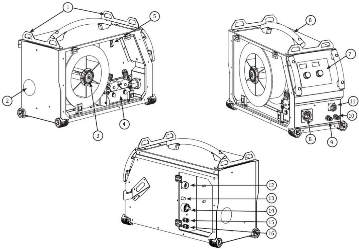
FIG-2
text_image
1 8.8.8 V 2 8.8.8 A m/min 5 6 7 10 -9 0 INDUCTANCE 9 11 +9 MODE 2T 4T SPOT/DELAY 13 14 15 16 17 18 press 3s setup memory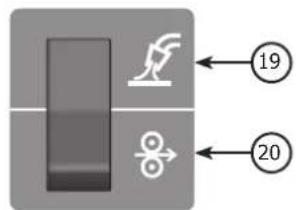
text_image
Diagram showing a device with a handle and a butterfly, labeled with numbers 19 and 20 pointing to it.FIG-3
A/
text_image
- Acier / Steel / Stahl / Acero / Staal / Aço - Inox - Stainless steel Gaine acier / Steel sheath / StahlseeleB/
text_image
- Alu NO USE Tube capillaire / Capillary Pipe / Kapillarrohr Gaine téflon / Teflon sheath / TeflonseeleFIG-4
natural_image
Close-up of a mechanical fan or impeller with a central hub and radial blades (no visible text or symbols)A
natural_image
Close-up of a mechanical component with a central hub and radial blades, no visible text or symbolsB
natural_image
Close-up of mechanical components with two circular flanges and bolts (no visible text or symbols)©
natural_image
Mechanical assembly with numbered components (4), no visible text or symbols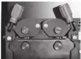
natural_image
Close-up of a mechanical clamp or bracket component with two flanged ends and three circular holes (no visible text or symbols)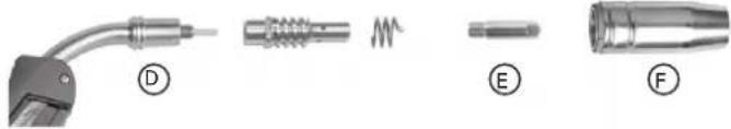
natural_image
Four types of welding torches and connectors labeled D, E, F, showing different mechanical designs (no text or symbols on the objects themselves)FIG-5
text_image
M5x10 (x4)AVERTISSEMENTS - RÈGLES DE SÉCURITÉ
CONSIGNE GÉNÉRALE

INSTALLATION – FONCTIONNEMENT PRODUIT
INTERFACE HOMME MACHINE (IHM) (FIG-2)
Read and understand the following safety recommendations before using or servicing the unit. Any change or servicing that is not specified in the instruction manual must not be undertaken.
The manufacturer is not liable for any injury or damage caused due to non-compliance with the instructions featured in this manual. In the event of problems or uncertainties, please consult a qualified person to handle the installation properly. Read the welding machine's instruction manual before using the wire feeder.
ENVIRONMENT
This equipment must only be used for welding operations in accordance with the limits indicated on the descriptive panel and/or in the user manual. The operator must respect the safety precautions that apply to this type of welding. In case of inadequate or unsafe use, the manufacturer cannot be held liable for damage or injury.
This equipment must be used and stored in a place protected from dust, acid or any other corrosive agent. Operate the machine in an open, or well-ventilated area.
Operating temperature:
Use between -10 and +40°C (+14 and +104°F).
Store between -20 and +55°C (-4 and 131°F).
Air humidity:
Lower or equal to 50% at 40°C (104°F).
Lower or equal to 90% at 20°C (68°F).
Altitude:
Up to 1000 meters above sea level (3280 feet).
INDIVIDUAL PROTECTIONS AND OTHERS
Arc welding can be dangerous and can cause serious and even fatal injuries.
Welding exposes the user to dangerous heat, arc rays, electromagnetic fields, noise, gas fumes, and electrical shocks. People wearing pacemakers are advised to consult with their doctor before using this device. Protect yourself and others. Ensure the following safety precautions are taken:

In order to protect you from burns and radiations, wear clothing without cuffs. These clothes must be insulated, dry, fireproof and in good condition, and cover the whole body.

Wear protective gloves which guarantee electrical and thermal insulation.

Use sufficient welding protective gear for the whole body: hood, gloves, jacket, trousers... (variable depending on the application/operation). Protect your eyes during cleaning operations. Do not operate whilst wearing contact lenses.
It may be necessary to install fireproof welding curtains to protect the area against arc rays, weld spatters and sparks.
Inform the people around the working area to never look at the arc ray or the molten metal, and to wear protective clothes.

Ensure ear protection is worn by the operator if the work exceeds the authorised noise limit. Ensure ear protection is worn by anyone in the welding area.
Stay away from moving parts (e.g. engine, fan...) with hands, hair, clothes etc...
Never remove the safety covers from the cooling trolley when the machine is plugged in - The manufacturer is not responsible for any accident or injury that happens as a result of not following these safety precautions.
The pieces that have just been welded are hot and may cause burns when manipulated. During maintenance work on the torch, you should make sure it's cold enough and wait at least 10 minutes before any intervention. The cooling trolley must be on when using a water cooled torch in order to ensure that the liquid does not cause any burns.
ALWAYS ensure the working area is left as safe and secure as possible to prevent damage or accidents.
WELDING FUMES AND GAS

The fumes, gases and dust produced during welding are hazardous. It is mandatory to ensure adequate ventilation and/or extraction to keep fumes and gases away from the work area. An air fed helmet is recommended in cases of insufficient air supply in the workplace.
Check that the air intake is in compliance with safety standards.
Caution, welding in small work areas requires surveillance from a safe distance. Welding certain pieces of metal containing lead, cadmium, zinc, mercury or beryllium can be extremely toxic. The user will also need to degrease the workpiece before welding.
Gas cylinders must be stored in an open or ventilated area. The cylinders must be in a vertical position secured to a support or trolley.
Do not weld in areas where grease or paint are stored.
FIRE AND EXPLOSIONS RISKS

Protect the entire welding area. Compressed gas containers and other inflammable material must be moved to a minimum safe distance of 11 meters.
A fire extinguisher must be readily available.
Be careful of spatter and sparks, even through cracks. It can be the source of a fire or an explosion.
Keep people, flammable objects and containers under pressure at a safe distance.
Welding of sealed containers or closed pipes should not be undertaken, and if opened, the operator must remove any inflammable or explosive materials (oil, petrol, gas...).
Grinding operations should not be directed towards the device itself, the power supply or any flammable materials.
GAS BOTTLE

Gas leaking from the cylinder can create a hazard if present in high concentrations around the work area.
Transport must be done safely: Cylinders closed and product off. Always keep cylinders in an upright position securely chained to a fixed support or trolley.
Close the bottle after any welding operation. Be careful with gas bottles placed in areas of high temperature, or in sunlight.
Cylinders should be located away from areas where they may be struck or subjected to physical damage.
Always keep gas bottles at a safe distance from arc welding or cutting operations, and any source of heat, sparks or flame.
Be careful when opening the valve on the gas bottle, it is necessary to remove the tip of the valve and make sure the gas meets your welding requirements.
ELECTRIC SAFETY

The machine must be connected to an earthed electrical supply. Use the recommended fuse size.
An electrical discharge can directly or indirectly cause serious or deadly accidents.
Do not touch any live part of the machine (inside or outside) when it is plugged in (Torches, earth cable, cables, electrodes) because they are connected to the welding circuit.
Before opening the device, it is imperative to disconnect it from the mains and wait 2 minutes, so that all the capacitors are discharged.
Do not touch the torch or electrode holder and earth clamp at the same time.
Damaged cables and torches must be changed by a qualified and skilled professional.
Make sure that the cable cross section is adequate with the usage (extensions and welding cables).
Always wear dry clothes in good condition, in order to be insulated from the electrical circuit. Wear insulating shoes, regardless of the environment in which you work in.
ELECTROMAGNETIC INTERFERENCES
The electric currents flowing through a conductor cause electrical and magnetic fields (EMF). The welding current generates an EMF field around the welding circuit and the welding equipment.
The EMF fields may disrupt some medical implants, such as pacemakers. Protection measures should be taken for people wearing medical implants. For example, access restrictions for passers-by or an individual risk evaluation for the welders.
All welders should take the following precautions in order to minimise exposure to the electromagnetic fields (EMF) generated by the welding circuit::
- position the welding cables together – if possible, attach them;
- keep your head and torso as far as possible from the welding circuit;
– never enroll the cables around your body; - never position your body between the welding cables. Hold both welding cables on the same side of your body;
- connect the earth clamp as close as possible to the area being welded;
- do not work too close to, do not lean and do not sit on the welding machine
- do not weld when you're carrying the welding machine or its wire feeder.

People wearing pacemakers are advised to consult their doctor before using this device.
Exposure to electromagnetic fields while welding may have other health effects which are not yet known.
TRANSPORT AND TRANSIT OF THE WIRE FEEDER
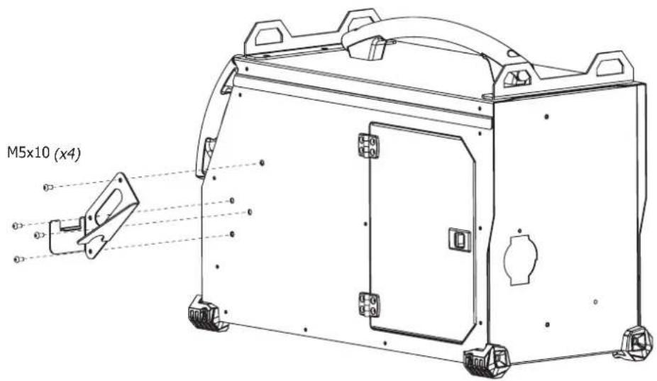
The wire feeder is equipped with handles for easy transportation. Be careful not to underestimate the machine's weight. The handle cannot be used to hang the machine from other equipment. Never lift the machine while there is a gas cylinder on the support shelf. A clear path is available when moving the item.
Do not place/carry the unit over people or objects.
The removal of the wire reel from the machine is recommended before undertaking any lifting operation.
The machine is fitted with non-insulated lifting eye bolts, they are designed for wire feeder maintenance and not for wire feeder lifting during welding operations. If they are used during welding, the eye bolts must be insulated from the building's earth.

Stray welding currents/voltages may destroy earth conductors, damage electrical equipment or cause components to warm up which may cause a fire.
- All welding connections must be firmly secured, check regularly!
- Check that the metal piece fixation is strong and without any electrical problems!
- Attach or hang all the electrically conductive elements, such as the trolley in order to insulate them
- Do not place any electrical equipment such as drills on top of the welding machine without insulating them!
- Always place welding torches or electrodes holders on an insulated surface when they're not in use!
INSTALLATION
Rules to follow :
- The wire feeder must be switched on with all access panels closed.
- Put the wire feeder on a floor with a maximum incline of 10^ .
- The machine must be placed in a sheltered area away from rain or direct sunlight.
- The equipment's protection level is IP23, which means :
- Protection against access to dangerous parts from solid bodies of a ≥12.5mm diameter and,
- Protection against the rain inclined at 60^ towards the vertical.
These devices can be used outside in accordance with the IP23 protection index.

The manufacturer does not incur any responsibility regarding damages to both objects and persons that result from an incorrect and/or dangerous use of the machine.
MAINTENANCE / RECOMMENDATIONS


- Maintenance should only be carried out by a qualified person. Annual maintenance is recommended.
-
Ensure the wire feeder is disconnected from the welding machine, and wait for two minutes before carrying out maintenance work.
-
Remove the casing 2 or 3 times a year to remove any excess dust. Take this opportunity to have the electrical connections checked by a qualified person, with an insulated tool.
- Regularly check the connection cable between the wire feeder and the machine. If damaged, the connection cable must be replaced.
- Warning! If the welding machine is transported/handled by another solution than the one recommended by the manufacturer; the wire feeder casing must be insulated from the transporting/handling solution.
Rules to follow - The wire feeder must be switched on with all access panels closed.
INSTALLATION – PRODUCT OPERATION
Only qualified personnel authorized by the manufacturer should perform the installation of the welding equipment. During set up, the operator must ensure that the machine is unplugged. It is recommended to use the welding cables supplied with the unit in order to obtain the optimum product settings.

Risk of injury due to moving parts!
The wire feeders contain moving parts that may catch hand, hair, clothes or tools which can lead to injuries! Take extra care.
- Do not place your hand on mobile/pivoting/wire feeding parts of the machine!
- Make sure that all panels remain closed when in use!
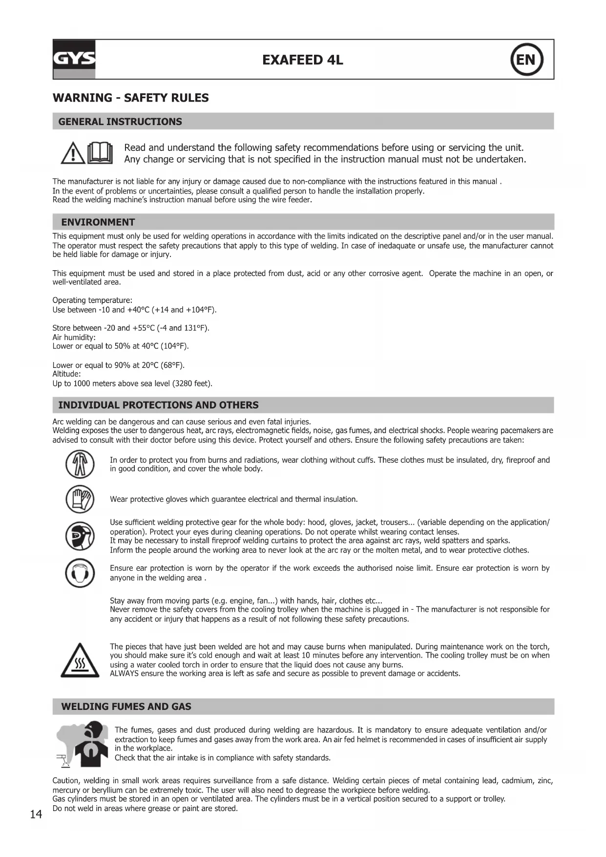
HARDWARE DESCRIPTION (FIG-1)
1- Lifting ring 9- Water connector
2- Connection cable access 10- Water connector
3- Reel support 11- Remote control cable connector
4- Wire feeding motor 12- Connection cable control connector
5- Rocker switch Wire inch / Gas purge 13- Gas connector
6- Transport handles. 14- Power relay connector
7- Man to Machine Interface 15- Water connector
8- EURO connector
16- Water connector
CONTROL BOARD (MMI) (FIG-2)
1- Voltage display
2- Wire speed / current display
3- Amperes indicator
4- m /mn indicator
5- Overheat indicator
6- Disruption of normal operations indicator
7- Voltage adjustment knob:
8- Wire speed / inductance adjustment knob
11- Inductance mode indicator
12- Active remote control indicator
13- Locked keypad indicator
14- Locked keypad button
15- Remote control selection button / remote control activation
16-2T indicator
17- 4T indicator
18- Spot/Delay indicator
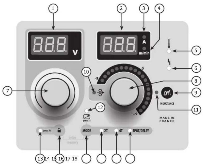
9- Inductance selection button 19- Gas purge
10- Wire speed indicator 20- Wire inching
POWER SUPPLY – STARTING UP
The EXAFEED 4L wire feeder has been solely designed to operate with the EXAGON 400 CC/CV welding machine (ref. 010925).
The connection between these two elements is done via one of the following connection cables :
| Cooling Length Section Reference | |||
| Air | 5m 70mm2 047587 | ||
| 10m | 70mm2 047594 | ||
| 95mm2 047600 | |||
| 15m | 95mm2 | 038349 | |
| 20m 038431 | |||
| Liquid | 1.8m 70mm2 037243 | ||
| 5m 70mm2 047617 | |||
| 10m | 70mm2 047624 | ||
| 95mm2 047631 | |||
| 15m | 95mm2 | 038448 | |
| 20m 038455 | |||
CONNECTIONS AND RECOMMENDATIONS
The connection between the welding machine and the wire feeder must be done while the power supply is off.
Connection cable on the wire feeder :
- Open the connection cable's access panel (FIG 1 - n°2)
- Pass the cable through the opening at the back of the wire feeder
- Lock the connection cable on the wire feeder by twisting it clockwise by 1/4 then lock the support using the screw supplied with the connection cable.
- Perform the connection.
Connection cable on welding machine :
- Connect the earth clamp on the positive (+) or negative (-) terminal depending on the wire type.
- Connect the connection cable on the remaining terminal for power.
- Connect the command connector on the 10 pin DIN connector located between the welding machine's power connectors.
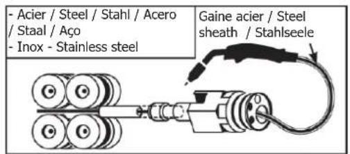
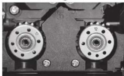
WIRE REEL INSTALLATION (FIG-4)
- Remove the torch shroud (FIG-4, F) and contact tip (FIG-4, E). Open the door of the machine.
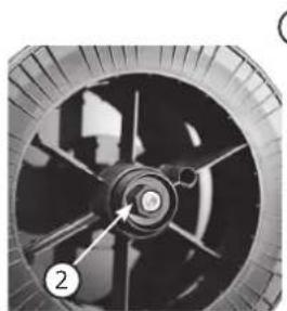
FIG-4, A :
- Place the reel on the driving pin of the reel support. For a 200 mm (10kg) wire reel, tighten the wire reel support to the maximum.
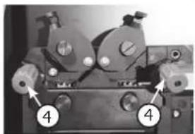
- Set the brake (FIG-4, 2) to prevent wire entanglement when the weld stops. In general, do not excessively tighten the brake, which would cause the motor to overheat.
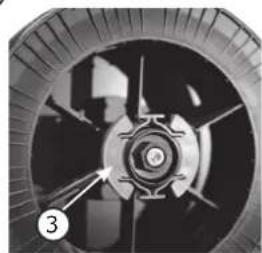
FIG-4, B :
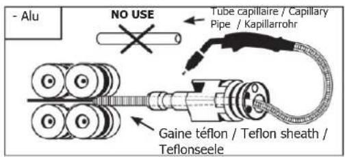
- Set the rollers that fit the intended use of the machine. The supplied rollers are double groove rollers ( 1/ and 1.2 ). The indication on the visible side of the roller is the diameter in use. For a 1.2 mm wire, use the 1.2 groove. For aluminium welding, use suitable rollers (U groove).
FIG-4, C :
To change the wire, proceed as follows :
- Untighten the wheels (FIG-4, 4) at the maximum and lower them, insert the wire, then close the wire feed motor and tighten the wheels according to the instructions.
- Start the motor by pressing the torch trigger (FIG 1 - n°5)
- Make the wire come out of the torch by 5 cm, then put a suitable contact tip at the end of the torch (FIG-4, E), as well as the shroud (FIG-4, F).
Remarks :

- A torch liner that is too narrow may cause wire feeding problems as well as motor overheating.
- The torch connector must also be securely tightened to prevent overheating.
- Check that neither the MIG/MAG wire nor the wire reel are in contact with the machine's mechanical parts, otherwise there is a danger of short-circuit.
MODE SELECTION ON THE WELDING MACHINE
On the machine, press the button MODE several times until the LED light switches on below the symbol 📄. Both display show — — and the knobs are inactive, all controls are now operated from the wire feeder's interface (FIG-2).
WELDING PARAMETERS SETTINGS
1. Setting the welding voltage :
Adjust the welding voltage using the main knob (○) depending on the work to be carried out. The voltage setpoint is indicated on the left side display.
2. Setting the wire speed :
Adjust the wire speed using the right knob depending on the work to be carried out. The speed setpoint is indicated on the right side display.
3. Setting the inductance :
While pressing the button m, turn the knob 2, the index shows a value from -9 à +9. The lower the inductance level, the harder and more guiding the arc. The higher the inductance and the softer the arc with little splatter.
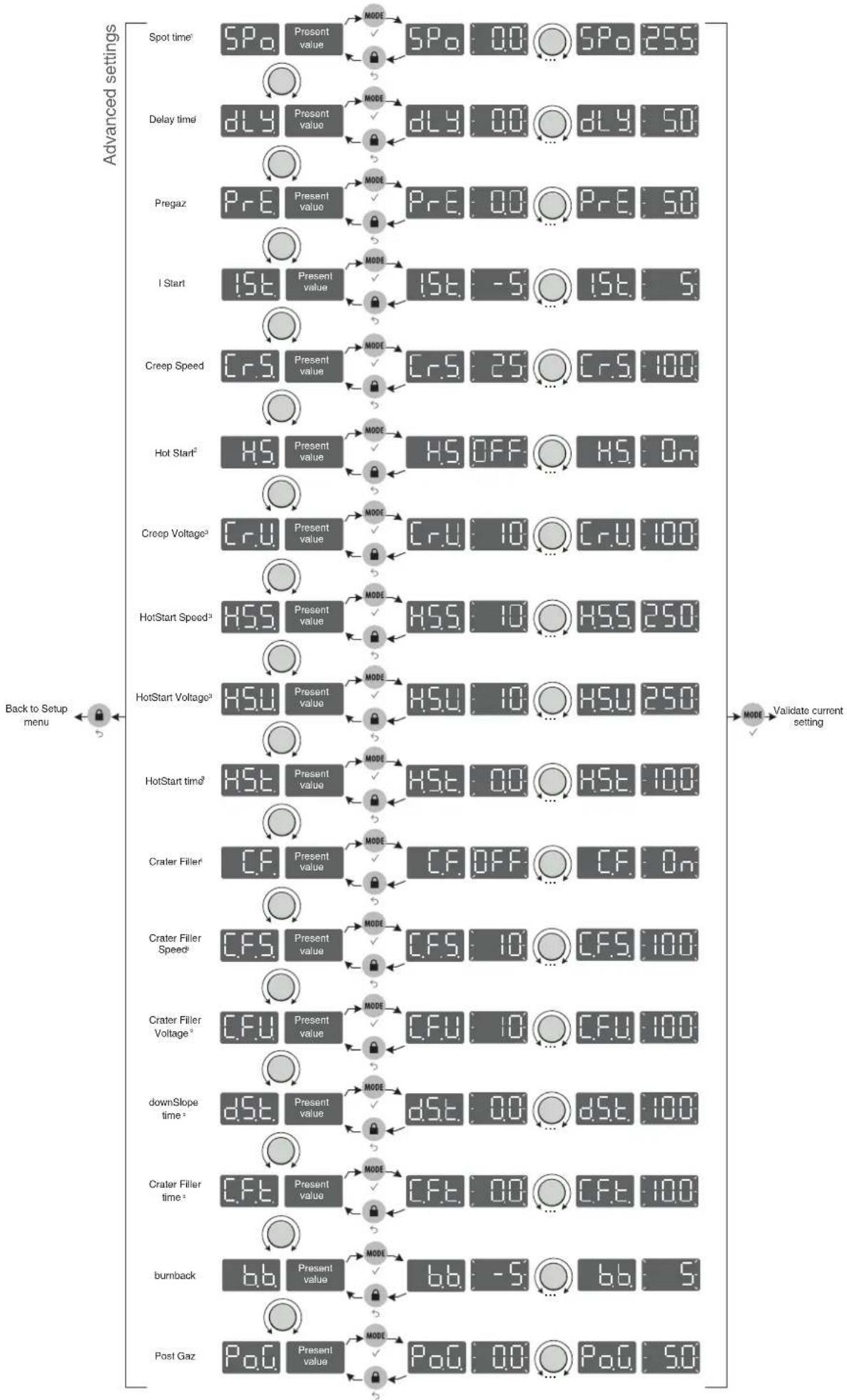
ACCESS TO ADVANCED SETTINGS
Refer to the chapter « menu access » for more details regarding welding parameters.
SPo. (1) « SPot », welding duration (in seconds) in Spot / Delay mode.
dLH. (1) « DeLaY », stop duration (in seconds) in Spot / Delay mode
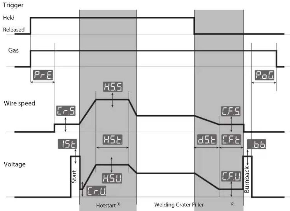
P_rE « PrEgaz », Pre gas, duration (in seconds) of the gas flow between the pressing of the trigger and the start of the wire feeding.
1.5t. « I Start », starting current (relative scale from -5 to +5), the default value is 0
« Creep Speed », wire creep speed (percentage) before arc ignition
H5. (2) « Hot Start », Activation / deactivation of hotstart settings (On/Off)
(3) « Creep Voltage », voltage (percentage) at arc ignition
HSS (3) « HotStart Speed », speed (percentage) during Hotstart
HSH (3) « HotStart Voltage », voltage (percentage) during Hotstart
HS. (3) « HotStart time », duration (in seconds) of the Hotstart phase
C.F. (4) « Crater Filler », activation / deactivation of crater filler mode (On/off)
(5) « Crater Filler Speed », speed (percentage) during crater filling
CFU ^(5) « Crater Filler Voltage », voltage (percentage) during crater filling phase
dSt. (5) « downSlope time », duration (in seconds) of the downslope from main welding current to crater filling phase
(5) « Crater Filler time », duration (seconds) of the crater filling phase
« burnback », energy required to draw back the wire (relative scale from -5 à +5), the default value is 0
P.O.C. « Post Gaz », duration (in seconds) of the gas flow after the welding stops
(1): these settings are only available in Spot / Delay mode.
(2): the Hotstart settings are only available in Spot / Delay mode.
(3): these settings are only visible if H.S. is set to « On ».
(4): the CraterFiller settings are only available in Spot / Delay mode.
(5): these settings are only visible if C.F. is set to « On ».
DISPLAY CURRENT/VOLTAGE DURING WELDING
During welding, the machine measures and displays the welding current and voltage. After the weld, the average current and voltage values are displayed during 30 seconds, as soon as a knob or a button is pressed, the welding parameters are displayed.
Depending on the operation (short-circuit, globular or spray-arc), the average voltage can slightly differ from the setpoint voltage.
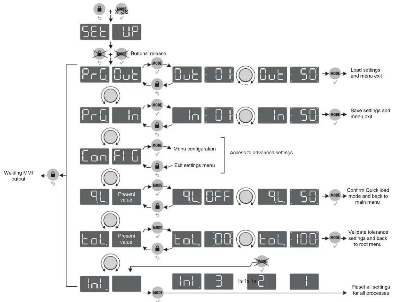
SAVE AND LOAD WELDING SETTINGSS
The current settings are automatically saved and loaded at start up.
On top of the current settings, it is also possible to save and load settings per each mode.
There are 50 memory slots
The saved settings include :
- voltage, wire speed and inductance,
- advanced settings.
- 2T / 4T / SPOT DELAY mode
Save new settings :
- Hold buttons and during 3 seconds. appears, release the buttons.
- Turn one of the two knobs - Validate by pressing the button .
-
The display indicates a memory set (01 to 50) while blinking.
-
Turn the knob to select the memory set in which the desired settings will be saved. Validate by pressing the button
- The settings are saved / the menu exit is instantaneous.
Load existing settings :
- Hold buttons

.MODE
during 3 seconds.

the butt
- Turn one of the two knobs. Validate by pressing the button.

- The display indicates a memory set (01 to 50) while blinking.
MODE
- Turn one of the two knobs to select the memory slot containing the settings to load. Validate by pressing the button. The settings are loaded / the menu exit is instantaneous.
Quick Load mode: Easy recall of saved welding parameters :
When the « Quick load » mode is active, the user can sequentially recall previously saved welding parameters, by briefly pressing/releasing the trigger. Slots 2 to 50 can store customisable welding parameters. (Example : Setting 5 will allow the user to recall, using he trigger, programs 01 to 05).
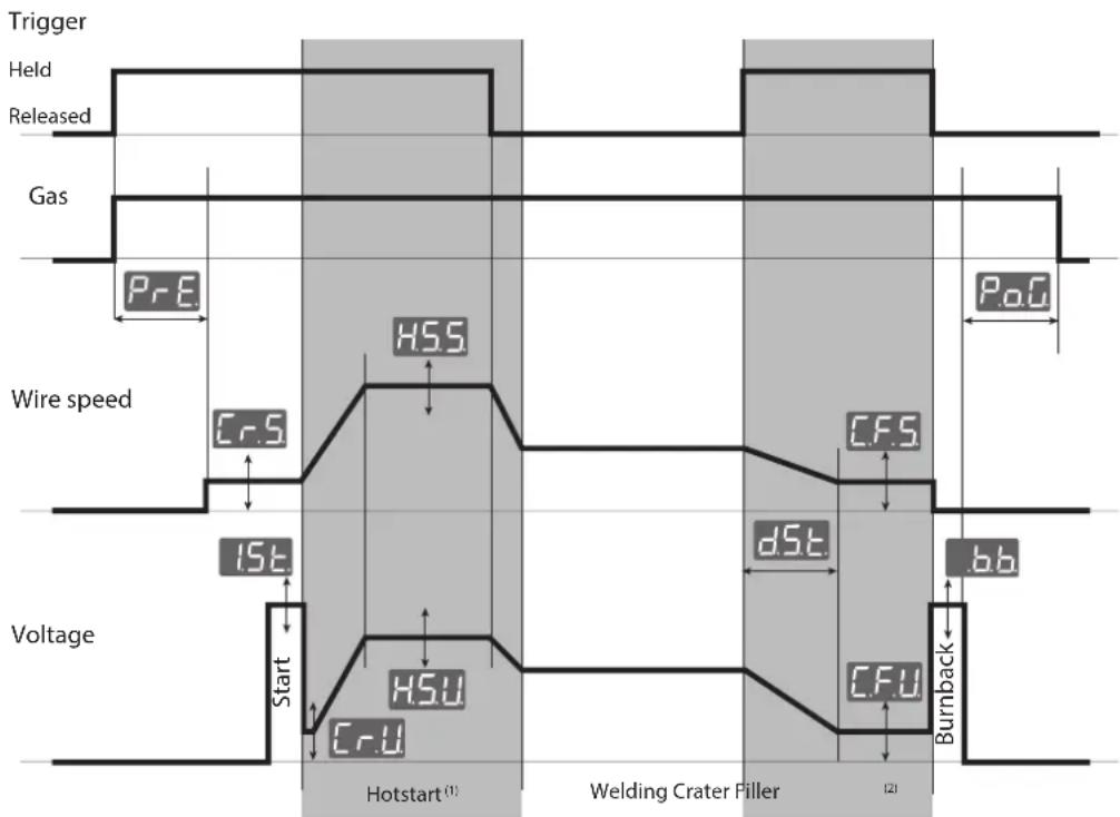
WELDING CYCLES
2T mode:
other
| Signal | Value | |--------|-------| | Trigger | HSS | | Held | 0 | | Released | 0 | | Gas | 0 | | Wire speed | 15E | | Wire speed | Cr.S | | Wire speed | HSt | | Wire speed | HSt | | Wire speed | Cr.U | | Voltage | 0 | | Voltage | HSU | | Voltage | Cr.U | | Hotstart (1) | 0 | | Welding Crater Filler (2) | 0 | | Welding Crater Filler (2) | c.F.S | | Welding Crater Filler (2) | dS.E | | Welding Crater Filler (2) | c.F.T | | Welding Crater Filler (2) | c.F.U | | Welding Crater Filler (2) | Burnback |(1): If the Hotstart phase feature is deactivated, the welding starts immediately after the arc ignition (Start).
(2): If the Crater Filler feature is deactivated, the wire is drawn back immediately after the trigger is released.
4T mode:
The 4T mode allows the user to manage various steps with the trigger The behaviour varies depending on the activation / deactivation of the Hotstart and Crater Filler features.
flowchart
graph TD
    A["Trigger"] --> B["Held"]
    B --> C["Released"]
    C --> D["Gas"]
    D --> E["PrE"]
    E --> F["Wire speed"]
    F --> G["1st"]
    G --> H["Start"]
    H --> I["Hotstart (1)"]
    I --> J["Welding Crater Filler"]
    J --> K["CrU"]
    K --> L["Burnback"]
    L --> M["bb"]
    M --> N["CrS"]
    N --> O["HSS"]
    O --> P["CrU"]
    P --> Q["HSU"]
    Q --> R["End"]
(1): if the Hotstart feature is active, the Hotstart phase lasts until the trigger is released. If the Hotstart feature is deactivated, the pregas phase lasts while the trigger is held (no graph).
^(2) : if the Crater Filler feature is active, the Crater Filler phase lasts while the trigger is held. If the Crater Filler is deactivated, the postgas phase lasts while the trigger is held (no graph).
Spot / Delay mode:
The Spot / Delay is a 2T mode to weld beads of a specific length (Spot settings expressed in seconds) with a specific spacing (Delay settings expressed in seconds). If the Delay setting is set to 0.0 seconds then a single weld bead will be welded, you will have to release and press the trigger again to weld another weld bead.
REMOTE CONTROL
A remote control (ref. 047679) can be connected to the EXAFEED wire feeder via the connector (FIG-1, 5). The remote control acts on the voltage (1st potentiometer) and the wire speed (2nd potentiometer). Thus these settings cannot be accessed on the wire feeder's interface.
LOCKING CONTROLS
That feature can lock the knobs and keypad to prevent accidental changes in the settings.
Operation :
Press the button for 3 seconds, the display shows and goes back to current display. The LED (FIG-2, n°13) switches on. No button is enabled, the knobs can adjust the voltage and wire speed (value at +/- of the percentage, defined by the «tol» setting) (see the welding machine's instruction manual).
To unlock the commands, press the button for 3 seconds, the display shows Un Loc then goes back to current display. The LED (FIG-2, n°13) switches off.
ACCESS TO MENUS
flowchart
graph TD
    A["SET UP"] --> B["SET UP + MODE"]
    B --> C["Buttons' release"]
    C --> D["ProgOut"]
    D --> E["MODE"]
    E --> F["Out 01 Out 50"]
    F --> G["MODE"]
    G --> H["Load settings and menu exit"]
    D --> I["Prog In"]
    I --> J["MODE"]
    J --> K["In 01 In 50"]
    K --> L["MODE"]
    L --> M["Save settings and menu exit"]
    D --> N["Con FIG"]
    N --> O["MODE"]
    O --> P["Menu configuration"]
    P --> Q["Exit settings menu"]
    Q --> R["Access to advanced settings"]
    R --> S["9L Present value"]
    S --> T["MODE"]
    T --> U["9L OFF 9L 50"]
    U --> V["Confirm Quick load mode and back to main menu"]
    S --> W["tol. Present value"]
    W --> X["MODE"]
    X --> Y["tol. 00 tol. 100"]
    Y --> Z["MODE"]
    Z --> AA["Validate tolerance settings and back to root menu"]
    W --> AB["Ini."]
    AB --> AC["MODE"]
    AC --> AD["Ini. 3 1s 1s 2 1"]
    AD --> AE["Reset all settings for all processes"]
flowchart
graph TD
    A["Spot time²"] --> B["5Po"]
    C["Delay time²"] --> D["dLy"]
    E["Pregaz"] --> F["PRe"]
    G["I Start"] --> H["1St"]
    I["Creep Speed"] --> J["CrS"]
    K["Hot Start²"] --> L["H.S"]
    M["Creep Voltage³"] --> N["CrU"]
    O["HotStart Speed³"] --> P["HSS"]
    Q["HotStart Voltage³"] --> R["HSU"]
    S["HotStart time³"] --> T["HSt"]
    U["Crater Filler⁴"] --> V["CF"]
    W["Crater Filler Speed⁵"] --> X["CF.S"]
    Y["Crater Filler Voltage⁶"] --> Z["CF.U"]
    AA["downSlope time⁷"] --> AB["dSt"]
    AC["Crater Filler time⁸"] --> AD["CF.T"]
    AE["burnback"] --> AF["b.b"]
    AG["Post Gaz"] --> AH["PoG"]

    B --> I
    D --> I
    F --> I
    H --> I
    J --> I
    L --> I
    N --> I
    P --> I
    V --> I
    V --> T
    V --> U
    V --> W
    V --> X
    V --> Z
    V --> Z
    V --> AB
    V --> AB
    V --> AD
    V --> AD
    V --> AF
    V --> AF

    style A fill:#f9f,stroke:#333
    style C fill:#f9f,stroke:#333
    style E fill:#f9f,stroke:#333
    style G fill:#f9f,stroke:#333
    style K fill:#f9f,stroke:#333
    style M fill:#f9f,stroke:#333
    style O fill:#f9f,stroke:#333
    style Q fill:#f9f,stroke:#333
    style S fill:#f9f,stroke:#333
    style U fill:#f9f,stroke:#333
    style V fill:#f9f,stroke:#333
    style X fill:#f9f,stroke:#333
    style Y fill:#f9f,stroke:#333
    style Z fill:#f9f,stroke:#333

    subgraph Advanced settings
        direction TB
        A2["5Po"]
        A3["Present value"]
        A4["MODE"]
        A5["5Po 0.0 ... 5Po 25S"]
        A6["Delay time²"]
        A7["Present value"]
        A8["MODE"]
        A9["dLy 0.0 ... dLy 5O"]
        A10["Present value"]
        A11["MODE"]
        A12["PrE 0.0 ... PrE 5O"]
        A13["Present value"]
        A14["MODE"]
        A15["1St -5 ... 1St 5"]
        A16["Present value"]
        A17["CREP Speed"]
        A18["CRS 25 ... CRS 100"]
        A19["Present value"]
        A20["MODE"]
        A21["Cr.S 25 ... Cr.S 100"]
        A22["Present value"]
        A23["MODE"]
        A24["H.S OFF ... H.S 0n"]
        A25["CRU 10 ... CrU 100"]
        A26["HSS 10 ... HSS 25O"]
        A27["HSU 10 ... HSU 25O"]
        A28["HSLT 0.0 ... HST 100"]
        A29["Present value"]
        A30["MODE"]
        A31["CF OFF ... CF 0n"]
        A32["Present value"]
        A33["MODE"]
        A34["CF.S 10 ... CF.S 100"]
        A35["CF.U 10 ... CF.U 100"]
        A36["dSt 0.0 ... dSt 100"]
        A37["CPF 0.0 ... CF.F 100"]
        A38["b.b -5 ... bb 5"]
        A39["PoG 0.0 ... PoG 5O"]
        end

    note right of A2: Back to Setup menu
        Back to Setup menu
        Back to Setup menu
        Back to Setup menu
        Back to Setup menu
        Back to Setup menu
        Back to Setup menu
        Back to Setup menu
        Back to Setup menu
        Back to Setup menu
        Back to Setup menu
        Back to Setup menu
        Back to Setup menu
        Back to Setup menu
        Back to Setup menu
        Back to Setup menu
        Back to Setup menu
        Back to Setup菜单
        Back to Setup menu
        Back to Setup menu
        Back to Setup menu
        Back to Setup menu
        Back to Setup menu
        Back to Setup menu
        Back to Setup menu
        Back to Setup menu
        Back to Setup menu
        Back to Setup menu
        Back to Setup menu
        Back to Setup menu
        Back to Setup menu
        Back to Setup menu
        Back to Setup menu
        Back to Setup menu
        Back-to-Setup menu
        Back-to-Setup menu
    end
(1): settings available only in Spot / Delay mode
(2): settings unavailable in Spot / Delay mode
(3): settings available only if Hot start mode is active (H.S. set to On).
(4): settings unavailable in Spot / Delay mode
(5): settings available only if Crater Filler is active (C.F. set to On)
WARRANTY
The warranty covers faulty workmanship for 2 years from the date of purchase (parts and labour).
The warranty does not cover:
- Transit damage.
- Normal wear of parts (eg. : cables, clamps, etc..).
- Damages due to misuse (power supply error, dropping of equipment, disassembling).
- Environment related failures (pollution, rust, dust).
In case of failure, return the unit to your distributor together with:
- The proof of purchase (receipt etc ...)
- A description of the fault reported
18- Signal-LED Spot/Delay
19- Gas-Ventil ein
WAARSCHUWING - VEILIGHEIDSINSTRUCTIES
ALGEMENE INSTRUCTIES

INTERFACE HUMAN MACHINE (IHM) (FIG-2)
text_image
Exploded view diagram of an electronic device with numbered components for identification| 1 | Clavier / Keypad / Tastatur / Teclado / Панель управления / Tastiera / Bedieningspaneel | 51966 |
| 2 | Circuit IHM Exafeed / Exafeed MMI circuit / Bedienfeldplatine Exafeed / Circuito Interfaz Exafeed / Плата IHM (интерфейс человек-машина) Exafeed / Circuito IHM Exafeed / Circuit IHM Exafeed | 97396C |
| 3 | Liquide de refroidissement / Cooling liquid / Brennerschlussbuchsen Kühlung / Líquido de refrigeración / Охлаждающая жидкость / Liquido di raffreddamento / Koelvloeistof | 71437 |
| 4 | Faisceau analogique / Analog connection cable / Brenneranschlussbuchse Steuerleitung / Cable conector analógico / Аналоговый соединительный шланг / Fascio cavo analogico / Analoge verbindingskabel | 91828ST |
| 5 | Pieds / Feet / Füße / Pies / Ножки / Piedini / Poten 56120 | |
| 6 | Poignée / Handle / Tragegriff / Mango / Ручка / Manico / Handvat | 56014 |
| 7 | Anneaux de levage / Lifting ring / Kranösen / Anillos de suspensión / Подъёмные кольца / Golfari di sollevamento / Oogbouten | 99415GT |
| 8 | Circuit dévidoir / Wire feeder circuit / Drahtvorschubplatine / Circuito devanadera / Плата подающего механизма / Circuito trainafilo / Circuit draadaanvoersysteem | 97394C |
| 9 | Moto dévidoir / Wire feeder motor / Drahtvorschubmotor / Motodevanadera / Моторизированный подающий механизм / Trainafilo / Haspel | 51259 |
| 10 | Faisceau interne / Internal connection cable / Anschlussbuchse Steurleitung / Conector cableado interno / Внутренний соединительный шланг / Fascio cavo interno / Interne verbindingskabel | 91683ST |
| 11 | Electrovanne / Solenoid valve / Gasventil / Electroválvula / Электроклапан / Elettromagnete / Gasventiel | 71542 |
| 12 | Embase puissance H24 mâle / DIN connector H24 male / Leistungsstecker / Conector potencia H24 macho / Цоколь мощности H24 папа / Base potenza H24 maschio / Vermogensstekker H24 mannelijk | 51481 |
| 13 | Raccord rapide / Quick connector / Anschlussbuchsen Kühlung / Conector rápido / Быстроразъёмное соединение / Collegamento rapido / Snelkoppelingen | 71437 |
| 14 | Support bobine / Reel support / Drahtförderrollen / Soporte de bobina / Держатель бобины / Draadspoel houder / Supporto bobina | 71613 |
SCHÉMA ÉLECTRIQUE / CIRCUIT DIAGRAM / STROMLAUFPLAN / ESQUEMA ELÉCTRICO / ЭЛЕКТРИЧЕСКАЯ СХЕМА / SCHEMA ELETTRICO / ELEKTRISCH SCHEMA
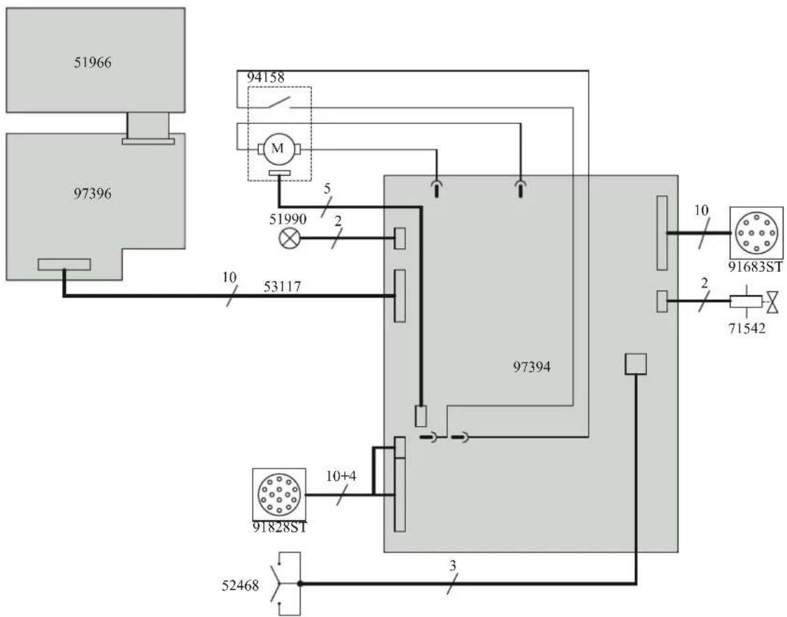
flowchart
graph TD
    A["97396"] --> B["51966"]
    A --> C["94158"]
    C --> D["M"]
    D --> E["51990"]
    E --> F["2"]
    F --> G["53117"]
    G --> H["97394"]
    H --> I["10"]
    H --> J["10+4"]
    J --> K["91828ST"]
    K --> L["52468"]
    L --> M["3"]
    M --> N["71542"]
    N --> O["91683ST"]
    O --> P["10"]
    style A fill:#ccc
    style B fill:#ccc
    style C fill:#ccc
    style D fill:#ccc
    style E fill:#ccc
    style F fill:#ccc
    style G fill:#ccc
    style H fill:#ccc
    style I fill:#ccc
    style J fill:#ccc
    style K fill:#ccc
    style L fill:#ccc
    style M fill:#ccc
    style N fill:#ccc
    style O fill:#ccc
    style P fill:#ccc
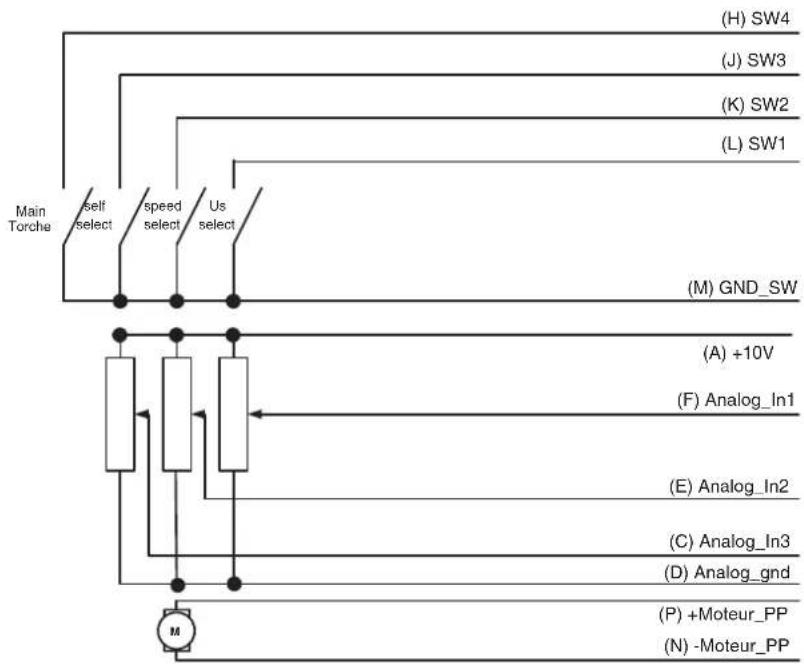
SCHÉMA ÉLECTRIQUE DE LA COMMANDE A DISTANCE ANALOGIQUE / ELECTRIC DIAGRAM FOR THE ANALOGUE REMOTE CONTROL/ SCHALTPLAN DES ANALOGEN FERNREGLERS / SCHEMA ELETTRICO DEL TELECOMANDO ANALOGICO / ELEKTRISCH SCHEMA VAN DE ANALOGE AFSTANDSBEDIENING / ЭЛЕКТРИЧЕСКАЯ СХЕМА АНАЛОГОВОГО ДИСТАНЦИОННОГО УПРАВЛЕНИЯ. / ESQUEMA ELÉCTRICO DEL CONTROL A DISTANCIA ANALÓGICO
flowchart
graph TD
    A["Main Torche"] --> B["Self select"]
    B --> C["speed select"]
    C --> D["Us select"]
    D --> E["(A) +10V"]
    E --> F["(F) Analog_In1"]
    F --> G["(E) Analog_In2"]
    G --> H["(C) Analog_In3"]
    H --> I["(D) Analog_gnd"]
    I --> J["(P) +Moteur_PP"]
    J --> K["(N) -Moteur_PP"]
    L["(H) SW4"] --> M
    N["(J) SW3"] --> O
    P["(K) SW2"] --> Q
    R["(L) SW1"] --> S
    T["(M) GND_SW"] --> U
    V["M"] --> W
LOGIQUE DE PRISE EN COMPTE DE LA TORCHE PUSH-PULL / WIRING THE PUSH-PULL TORCH / LOGIK DES EINBEZUGS DES PUSH-PULL-BRENNERS / LOGICA DI CONSIDERAZIONE DELLA TORCIA PUSH-PULL / LOGICA VAN DE INGEBRUIKNAME VAN DE PUSH-PULL TOORTS / ОПРЕДЕЛЕНИЕ ПОДКЛЮЧЕНИЯ ГОРЕЛКИ PUSH-PULL / ESPECIFICACIÓN DE LA ANTORCHA PUSH-PULL
| SW5 Analog_In4 Detect | |
| 0 0 No Push-Pull | |
| 0 =+10V No Push-Pull | |
| 1 0 Push-Pull 24V | |
| 1 =+10V Push-Pull 42V |
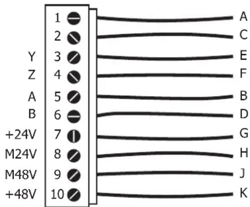
SPÉCIFICATION FAISCEAU ARRIÈRE DÉVIDOIR (VERS GÉNÉRATEUR) / SPECIFICATIONS FOR THE INTERCONNECTION CABLE (WIRE FEEDER INTO POWER SOURCE) / SPEZIFIKATION DES HINTEREN DRAHTVORSCHUBKOFFER (NICHT BEIM SCHWEISS-☐ GERÄT) / SPECIFICHE DEL FASCIO CAVO POSTERIORE DEL TRAINAFILO (VERSO IL GENERATORE) / SPECIFICATIE KABEL ACHTERZIJDE DRAADAANVOERSYSTEM (NAAR DE GENERATOR) / СПЕЦИФИКАЦИЯ РУКАВА СЗАДИ ПОДАЮЩЕГО УСТРОЙСТВА (К ИСТОЧНИКУ) / ESPECIFICACIÓN DEL CABLE DE UNIÓN TRASERO DE LA DEVANADERA (HACIA EL GENERADOR)
text_image
1 2 3 4 5 6 7 8 9 10 Y Z A B +24V M24V M48V +48V A C E F B D G H J K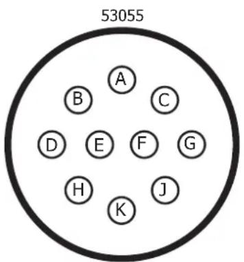
text_image
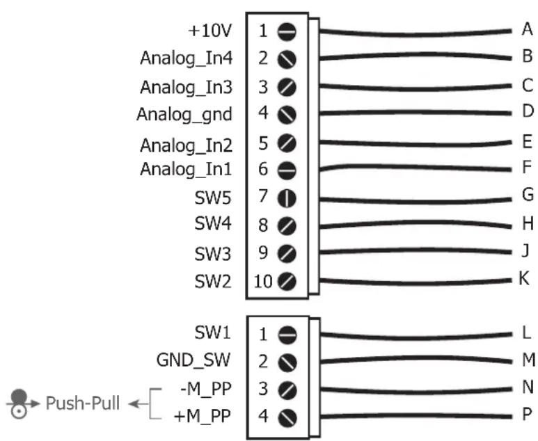
53055 A B C D E F G H K JSPÉCIFICATION FAISCEAU ANALOGIQUE (AVANT DÉVIDOIR) / SPECIFICATIONS FOR THE ANALOGUE INTERCONNECTION CABLE (FRONT OF THE WIRE FEEDER) / SPECIFICA FASCIOCAVO ANALOGICO (PRE-TRAINAFILO) / SPECIFICATIE ANALOGE KABEL (VOOR HET DRAADAANVOERSYSTEEM) / СПЕЦИФИКАЦИЯ АНАЛОГОВОГО РУКАВА (ПЕРЕД ПОДАЮЩИМ УСТРОЙСТВОМ) / ESPECIFICACIÓN DEL CONECTOR ANALÓGICO (PARTE FRONTAL DE LA DEVANADERA)
text_image
+10V Analog_In4 Analog_In3 Analog_gnd Analog_In2 Analog_In1 SW5 SW4 SW3 SW2 1 2 3 4 5 6 7 8 9 10 A B C D E F G H J K SW1 GND_SW -M_PP +M_PP L M N P Push-Pull ←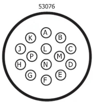
text_image
53076 A B K J L C P H N M D G F ESPÉCIFICATIONS TECHNIQUES / TECHNICAL SPECIFICATIONS / TECHNISCHE DATEN / ESPECIFICACIONES TECNICAS / ТЕХНИЧЕСКИЕ СПЕЦИФИКАЦИИ / SPECIFICHE TECNICHE / TECHNISCHE GEGEVENS
EXAFEED 4L
| Tensions d'alimentation (DC) – issues du générateur / Power supply voltage (DC) – generator output / Versorgungsspannung (DC) – aus dem Generator / Напряжения питания (DC) – из источника / Tensione di alimentazione (DC) - creata dal generatore / Voedingsspanning (DC) - afkomstig uit het lasapparaat / Tensioni di alimentazione (DC) - dal generatore | U11 = 48V-2A / U12 = 24V-1A |
| Vitesse de moteur / Motor speed / Versorgungsspannung (DC) – aus dem Generator / Скорость двигателя / Velocidad del motor / Snelheid motor / Velocità del motore | 1.0-22.0m/mn |
| Connectique de torche / Torch connector / Brenneranschluss / Соединения горелки / Sistema de conexión de linterna / Aansluiting toorts / Sistema di connessione della torcia elettrica | EURO |
| Bobines supportées / Supported wire reels / geeignete Drahtspulen / Подходящие бобины / Bobinas soportadas / Ondersteunde spoelen / Bobine supportate | 200mm / 300mm |
| Fils supportés / Supported wires / Geeignete Drähte / Подходящие виды проволоки / Hilos soportados / Ondersteunde draden / Fili supportati | Fe : 0.6mm – 1.6mm |
| SS : 0.8mm – 1.6mm | |
| Al : 1.0mm – 1.6mm | |
| Cored : 0.9mm – 2.4mm | |
| Facteur de marche à 40°C (10 min)* Norme IEC 60974-1.Duty cycle at 40°C (10 min)* Standard IEC 60974-1.Einschaltdauer @ 40°C (10 min)* IEC 60974-1-Norm.ПВ% при 40°C (10 мин)* Норма IEC 60974-1.Ciclo de trabajo a 40°C (10 min)* Norma IEC 60974-1.Inschakelduur bij 40°C (10 min)* Norm IEC 60974-1.Ciclo di lavoro a 40°C (10 min)* Norma IEC 60974-1. | 60% 500A |
| 100% 400A | |
| Gaz de protection / Protectice gas / Schutzgas / Защитный газ / Gases de protección / Beschermingsgas / Gas di protezione ( Pmax = 5 bar ) | Fonction du matériau à souderDepending on the material to weldAbhängig vom zu schweißenden MaterialDependiendo del material a soldarФункция свариваемого материалаFunctie van het te lassen materiaalFunzione del materiale da saldare |
| Type de galet / Drive roller type / Drahtführungsrolle-Typ / Tipo de rodillo / Тип ролика / Type draadaanvoerrol / Tipo di rullo | C |
| Température de fonctionnement / Functioning temperature / Betriebstemperatur / Рабочая температура / Temperatura de funcionamiento / Gebruikstemperatuur / Campo di temperatura d’esercizio | -10°C +40°C |
| Température de stockage / Storage temperature / Lagertemperatur / Lagerungstemperatur / Температура хранения / Temperatura de almacenamiento / Bewaartemperatuur / Temperatura di stoccaggio | -20°C +55°C |
| Degré de protection / Protection level / Schutzart / Степень защиты / Grado de protección / Beschermingsklasse / Grado di protezione | IP23 |
| Dimensions (Lxlxh) / Dimensions (LxWxH) / Abmessungen (LxBxT) / Размеры (ДхШхВ) / Dimensiones (LxAnxAl) / Afmetingen (Lxbxh) / Dimensioni (Lxlxh) | 67.5 x 30 x 23 cm |
| Poids / Weight / Gewicht / Bec / Peso / Gewicht / Peso 19 kg |
*Les facteurs de marche sont réalisés selon la norme IEC 60974-1 à 40°C et sur un cycle de 10 min.
Lors d'utilisation Intensive (supérieur au facteur de marche) la protection thermique peut s'enclencher, dans ce cas, l'arc s'éteint et le témoin s'allume. L'assez l'appareil alimenté pour permettre son réfroidissement jusqu'à annulation de la protection.
L'appareil, en fonction du mode choisi, décrit une caractéristique soit de type courant constant, soit de type tension constante.
*The duty cycles are measured according to standard IEC 60974-1 à 40°C and on a 10 min cycle.
While under Intensive use (> to duty cycle) the thermal protection can turn on, in that case, the arc switches off and the indicator switches on. KKeep the machine's power supply on, to enable cooling until thermal protection cancellation.
The device, depending on the selected mode, describes either an output characteristic of «constant current» type, or an output characteristic of «constant voltage» type.
*Einschaltdauer gemäß IEC 60974-1 (10 Minuten - 40°C).
Bei sehr intensivem Gebrauch (>Einschaltdauer) kann der Thermoschutz ausgelöst werden. In diesem Fall wird der Lichtbogen abgeschaltet und die entsprechende Warnung erscheint auf der Anzeige. Das Gerät zum Abkühlen nicht ausschalten und laufen lassen bis das Gerät wieder bereit ist.
Das beschriebene Gerät hat eine Ausgangscharakterisitk vom Typ «Konstantspannung».
*Los factores de funcionamiento se realizan según la norma IEC 60974-1 a 40°C y a lo largo de un ciclo de 10 minutos.
Durante el uso intensivo (por encima del ciclo de trabajo) se puede activar la protección térmica, en este caso el arco se apagará y la luz indicadora se encenderá. Deje la unidad encendida para que se enfrié hasta que se cancelle la protección.
Dependiendo del modo elegido, el dispositivo describe una característica del tipo de corriente constante o de tensión constante.
*ПВ% указаны по норме IEC 60974-1 при 40°C и для 10-минутного цикла.
При интенсивном использовании (> ПВ%) может включиться тепловая защита. В этом случае дуга погаснет и загорится индикатор
Оставьте аппарат подключенным к питанию, чтобы он остыл до полной отмены защиты.
Аппарат, в зависимости от выбранного режима, имеет характеристику либо «постоянный ток», либо «постоянное напряжение».
*De inschakelduur is gemeten volgens de norm IEC 60974-1 bij een temperatuur van 40°C en bij een cyclus van 10 minuten.
Bij intensief gebruik (superieur aan de inschakelduur) kan de thermische beveiliging zich in werking stellen. In dat geval gaat de boog uit en gaat het beveiligingslampje branden.
Laat het apparaat aan de netspanning staan om het te laten afkoelen, totdat de beveiliging afslaat.
Het apparaat, afhankelijk van de gekozen modus, heeft een eigenschap van constante stroom of van contante spanning.
*I cicli di lavoro sono realizzati secondo la norma IEC 60974-1 a 40°C e su un ciclo di 10 min.
Durante l'uso intensivo (> al ciclo di lavoro) la protezione termica può attivarsi, in questo caso, l'arco si spegne e la spia si illumina. Lasciate il dispositivo collegato per permetterne il raffreddamento fino all'annullamento della protezione.
Il dispositivo, in base alla modalità scelta, presenta una caratteristica sia di tipo corrente costante che di tipo tensione costante.
ICÔNES / SYMBOLS / SYMBOLE / ICONOS / СИМВОЛЫ / ICONE / ZEICHENERKLÄRUNG
 ____ ____ | - Attention I Lire le manuel d'instruction avant utilisation.- Caution I Read the user manual.- Achtung! Betriebsanleitung vor Gebrauch losen | - iCuidado! Lea el manual de instrucciones antes de su uso.- Внимание! Пронтите инструкцию перед использованием.- Let op! Lees voor gebruik aandachtig de gebruiksaanwijzing door.- Attenzione! Leggere il manuale d'istruzioni prima dell'uso. |
| IEC 60974-5 | - Le dévidoir est conforme à la norme IEC 60974-5.- The wire feeder complies with the IEC 60974-5 standard.- Der Drahtvorschubkoffer entspricht der Norm IEC 60974-5. | - Подающее устройство соответствует норме IEC 60974-5.- Il trainafilo è conforme alla norma IEC 60974-5.- Het draadaanvoersysteem voldoet aan de eisen van de norm IEC 60974-5.- Il dispositivo rispetta la norma 60974-5. |
 | - Soudage MIG / MAG- MIG / MAG welding- MIG / MAG-Schweißen | - Soldadura MIG / MAG- Сварка MIG / MAG- MIG / MAG lassen- Saldatura MIG / MAG |
•  | - Vitesse du fil- Wire speed- Drahtgeschwindigkeit | - Velocidad de hilo- Скорость проволоки- Draadsnelheid- Velocità di filo |
| IP23 | - Protection contre l'accès aux parties dangereuses des corps solides de ≥ 12,5mm et chute d'eau (60° par rapport à la verticale).- Protected against the access of dangerous parts from solid bodies of a ≥ 12,5mm and water (60° towards the vertical).- Gegen Eindringen von Körpern mit einem Durchmesser >12,5mm und gegen Sprühwasser geschützt (Einfallwinkel 60° horizontal)- Защита от попадания в опасные зоны твердых тел ≥ 12,5mm и капель воды (горизонтальный наклон 60°).- Protezione contro l'accesso alle aree pericolose di corpi solidi di ≥ 12,5mm e cadute d'acqua (60° rispetto alla verticale).- Bevelligid tegen toegang tot gevaarlijke delen van ≥ 12,5mm , en tegen regendruppels (60° ten opzichte van een verticale lijn).- Protezione contro l'accesso a parti pericolose di corpi solidi di ≥ 12,5mm e cascata (60° rispetto alla verticale). | |
 | - Courant de soudage continu.- Direct welding current.- Invertergleichstromquelle (DC) | - Постоянный сварочный ток.- Corrente di saldatura continua.- DC lasstroom- Corrente di saldatura continuo |
 | - Facteur de marche selon la norme IEC 60974-1 (10 minutes – 40°C).- Duty cycle according to standard EN 60974-1 (10 minutes – 40°C).- Einschaltdauer @ 40°C (10 min)* IEC 60974-1-Norm. | - ПВ% согласно норме EN 60974-1 (10 минут – 40°C).- Ciclo di lavoro conforme alla norma IEC 60974-1 (10 minuti – 40°C).- Inschakelduur volgens de norm IEC 60974-1 (10 minuten – 40°C).- Ciclo di lavoro conforme alla norma IEC 60974-1 (10 minuti – 40°C). |
| I2 | - Courant de soudage conventionnel correspondant.- Corresponding conventional welding current.- Entsprechender Schweißstrom. | - Соответствующий номинальный сварочный ток.- Corrente di saldatura convenzionale corrispondente.- Overeenkomstige conventionele lasstroom.- Corrente di saldatura convenzionale |
| A | Ampères - Amperes - Ampere - Amperios - Амперы - Ampère - Amper | |
| U11U12 | - Tensions d'alimentation assignés.- Rated power supply voltage- Netzspannung | - Номинальное напряжение питания- Tensioni di alimentazione nominali- Nominale voedingsspanning- Tensioni nominali di alimentazione. |
 | - Courants d'alimentation assignés.- Rated power supply current- Eingangstrom | - Номинальный ток питания- Correnti di alimentazione nominali- Nominale voedingsstroom- Correnti nominali di alimentazione. |
| CE | - Matériel conforme aux Directives européennes. La déclaration UE de conformité est disponible sur notre site (voir à la page de couverture).- Device complies with europeans directives. The EU declaration of conformity is available on our website (see cover page).- Gerät entspricht europäischen Richtlinien. Die Konformitätserklärung finden Sie auf unsere Webseite.- Aparato conforme a las directivas europeas. La declaración de conformidad UE está disponible en nuestra página web (dirección en la portada).- Устройство соответствует директивам Еаросюзоза. Декларация о соответствии доступна для просмотра на нашем сайте (ссылка на обложке).- Apparaat in overeenstemming met de Europese richtlijnen. De verklaring van overeenstemming is te downloaden op onze website (adres vermeld op de omslag).- Materiale in conformità alle Direttive europee. La dichiarazione di conformità è disponibile sul nostro sito (vedere sulla copertina). | |
 | - Matériel conforme aux normes Marocaines. La déclaration C_P (CMIM) de conformité est disponible sur notre site (voir à la page de couverture).- Equipment in conformity with Moroccan standards. The declaration C_P (CMIM) of conformity is available on our website (see cover page).- Das Gerät entspricht die marokkanischen Standards. Die Konformitätserklärung C_M (CMIM) ist auf unserer Webseite verfügbar (siehe Titelseite).- Equipamiento conforme a las normas marroquies. La declaración de conformidad C_R (CMIM) está disponible en nuestra página web (ver página de portada).- Товар соответствует нормам Марокко. Декларация C_P (CMIM) доступна для скачивания на нашем сайте (см на типульной странице).- Dit materiaal voldoet aan de Marokkaanse normen. De verklaring C_R (CMIM) van overeenstemming is beschikbaar op onze internet site (vermeld op de omslag).- Materiale conforme alle normative marocchine. La dichiarazione C_E (CMIM) di conformità è disponibile sul nostro sito (vedeti scheda del prodotto) | |
 | - Matériel conforme aux exigences britanniques. La déclaration de conformité britannique est disponible sur notre site (voir à la page de couverture).- Equipment in compliance with British requirements. The British Declaration of Conformity is available on our website (see home page).- Das Gerät entspricht den britischen Richtlinien und Normen. Die Konformitätserklärung für Grossbritannien ist auf unserer Internetseite verfügbar (siehe Titelseite).- Equipo conforme a los requisitos británicos. La Déclaration de Conformidad Británica está disponible en nuestra página web (véase la portada).- Материал соответствует требованиям Великобритании. Заявление о соответствии для Великобритании доступно на нашем век-сайте (см. главную страницу).- Materiaal conform aan de Britse eisen. De Britse verklaring van overeenkomt is beschikbaar op onze website (zie omslagpagina).- Materiale conforme alla esigenze britanniche. La dichiarazione di conformità britannica è disponibile sul nostro sito (vedere pagina di copertina). | |
 | - Produit recyclable qui relève d'une consigne de tri- This product should be recycled appropriately- Produkt muss getrennt ensorgt werden. Werfen Sie das Gerät nicht in den Hausmüll.- Producto reciclable que requiere una separación determinada.- Этот annapat подлежит утилизации- Product recyclebaar, niet bij het huishoudelijk afval gooien- Prodotto riciclabile che assume un ordine di smistamento | |
 | - Marque de conformité EAC (Communauté économique Eurasienne).- EAEConformity marking (Eurasian Economic Community).- EAC-Konformitätszeichen (Eurasische Wirtschaftsgemeinschaft) | - Знак соответствия EAC (Евразийское экономическое сообщество).- Marchio di conformità EAC (Comunità economica Eurasiatica).- EAC (Euraziatische Economische Gemeenschap) merkteken van overeenstemming- Marca di conformità EAC (Comunità Economica Eurasiatica) |
 | - Ce matériel fait l'objet d'une collecte sélective selon la directive européenne 2012/19/UE. Ne pas jeter dans une poubelle domestique !- This hardware is subject to waste collection according to the European directives 2002/96/UE. Do not throw out in a domestic bin/waste !- Für die Entsorgung Ihres Gerätes gelten besondere Bestimmungen (Elektroschrott) gemäß europäische Bestimmung 2012/19/EU. Es darf nicht mit dem Hausmüll entsorgt werden.- Это оборудование подлежит переработке согласно директиве Евросюзоза 2012/19/UE. Не выбрасывать в общий мусорсорбник!- Questo dispositivo è oggetto di raccolta differenziata secondo la direttiva europea 2012/19/UE. Non gettare nei rifiuti domestici !- Afzonderlijke inzameling vereist volgens de Europese richtlijn 2012/19/UE. Gool het apparaat niet bij het huishoudelijk afval !- Questo materiale è soggetto alla raccolta differenziata seguendo la direttiva europea 2012/19/UE. Non smaltire coni rifiuti domestici! | |
| - Information sur la température (protection thermique).- Temperature information (thermal protection).- Information zur Temperatur (Thermoschutz) | - Информация по температуре (термозащита).- Informazioni sulla temperatura (protezione termica).- Informatie over de temperatuur (thermische beveiliging).- Informazione sulla temperatura (protezione termiche) | |
 | - Commande à distance- Remote control- Fernregler | - Дистанционное управление.- Comando a distanza.- Afstandsbediening.- Telecomando a distanza |
| - Purge gaz- Gas purge- Gasventil einschalten | - Epurazione del gas- Продукка взором- Afvoeren gas- Gas di lavaggio | |
 | - Entrée du circuit de liquide de refroidissement- Cooling liquid input.- Wasservorlauf | - Entrada de líquido de refrigeración.- Вход для охлаждающей жидкости.- Ingang koelvloelstof.- Entrata di liquido di raffreddamento |
 | - Sortie du circuit de liquide de refroidissement- Cooling liquid output.- Wasserrücklauf | - Salida de líquido de refrigeración.- Выход для охлаждающей жидкости.- Afvoer koelvloelstof- Uscita di liquido di raffreddamento |
 | - Entrée du gaz- Gas input- Gaseingang | - Entrada de gas- Подача газа- Ingang gas- Entrata di gas |
| - Sortie de gaz- Gas output- Gasausgang | - Salida de gas- Выход газа- Uitvoer gas- Uscita di gas | |
| - Polarité positive- Positive polarity- Positive Polarität | - Polaridad positiva- положительная полярность- Positieve polariteit- Polarità positiva | |
| - Polarité négative- Negative polarity- Negative Polarität | - Polaridad negativa- отрицательной полярности- Negatieve polariteit- Polarità negativa | |