GYS Exatig HF - Welding machine

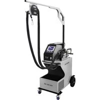
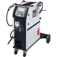
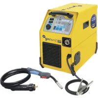
Exatig HF - Welding machine GYS - Free user manual and instructions

Find the device manual for free Exatig HF GYS in PDF.

📄 88 pages English EN 💬 AI Question
Notice GYS Exatig HF - page 14

Questions des utilisateurs sur Exatig HF GYS

0 question sur cet appareil. Repondez a celles que vous connaissez ou posez la votre.

Poser une nouvelle question sur cet appareil

L'email reste privé : il sert seulement à vous prévenir si quelqu'un répond à votre question.

Aucune question pour l'instant. Soyez le premier à en poser une.

Download the instructions for your Welding machine in PDF format for free! Find your manual Exatig HF - GYS and take your electronic device back in hand. On this page are published all the documents necessary for the use of your device. Exatig HF by GYS.

USER MANUAL Exatig HF GYS

INSTALLATION – FONCTIONNEMENT PRODUIT

DB torch L torch DB + P torch

ANOMALIES, CAUSES, REMÈDES

GENERAL INSTRUCTIONS Read and understand the following safety recommendations before using or servicing the unit. Any change or servicing that is not specied in the instruction manual must not be undertaken. The manufacturer is not liable for any injury or damage caused due to non-compliance with the instructions featured in this manual . In the event of problems or uncertainties, please consult a qualied person to handle the installation properly. ENVIRONMENT This equipment must only be used for welding operations in accordance with the limits indicated on the descriptive panel and/or in the user manual. The operator must respect the safety precautions that apply to this type of welding. In case of inedaquate or unsafe use, the manufacturer cannot be held liable for damage or injury. This equipment must be used and stored in a place protected from dust, acid or any other corrosive agent. Operate the machine in an open, or well-ventilated area. Operating temperature: Use between -10 and +40°C (+14 and +104°F). Store between -20 and +55°C (-4 and 131°F). Air humidity: Lower or equal to 50% at 40°C (104°F). Lower or equal to 90% at 20°C (68°F). Altitude: Up to 1000 meters above sea level (3280 feet).

PROTECTION OF THE INDIVIDUALS

Arc welding can be dangerous and can cause serious and even fatal injuries. Welding exposes the user to dangerous heat, arc rays, electromagnetic elds, noise, gas fumes, and electrical shocks. People wearing pacemakers are advised to consult with their doctor before using this device. To protect oneself as well as the other, ensure the following safety precautions are taken: In order to protect you from burns and radiations, wear clothing without cus. These clothes must be insulated, dry, reproof and in good condition, and cover the whole body. Wear protective gloves which guarantee electrical and thermal insulation. Use sucient welding protective gear for the whole body: hood, gloves, jacket, trousers... (varies depending on the application/ operation). Protect the eyes during cleaning operations. Do not operate whilst wearing contact lenses. It may be necessary to install reproof welding curtains to protect the area against arc rays, weld spatters and sparks. Inform the people around the working area to never look at the arc nor the molten metal, and to wear protective clothes. Ensure ear protection is worn by the operator if the work exceeds the authorised noise limit (the same applies to any person in the welding area). Stay away from moving parts (e.g. engine, fan...) with hands, hair, clothes etc... Never remove the safety covers from the cooling unit when the machine is plugged in - The manufacturer is not responsible for any accident or injury that happens as a result of not following these safety precautions. The pieces that have just been welded are hot and may cause burns when manipulated. During maintenance work on the torch or the electrode holder, you should make sure it’s cold enough and wait at least 10 minutes before any intervention. The cooling unit must be on when using a water cooled torch in order to ensure that the liquid does not cause any burns. ALWAYS ensure the working area is left as safe and secure as possible to prevent damage or accidents.

WELDING FUMES AND GAS

The fumes, gases and dust produced during welding are hazardous. It is mandatory to ensure adequate ventilation and/or extraction to keep fumes and gases away from the work area. An air fed helmet is recommended in cases of insucient air supply in the workplace. Check that the air intake is in compliance with safety standards. Care must be taken when welding in small areas, and the operator will need supervision from a safe distance. Welding certain pieces of metal containing lead, cadmium, zinc, mercury or beryllium can be extremely toxic. The user will also need to degrease the workpiece before welding. Gas cylinders must be stored in an open or ventilated area. The cylinders must be in a vertical position secured to a support or trolley. Do not weld in areas where grease or paint are stored.MADE IN FRANCE

Protect the entire welding area. Compressed gas containers and other inammable material must be moved to a minimum safe distance of 11 meters. A re extinguisher must be readily available. Be careful of spatter and sparks, even through cracks. It can be the source of a re or an explosion. Keep people, ammable objects and containers under pressure at a safe distance. Welding of sealed containers or closed pipes should not be undertaken, and if opened, the operator must remove any inammable or explosive materials (oil, petrol, gas...). Grinding operations should not be directed towards the device itself, the power supply or any ammable materials. GAS BOTTLE Gas leaking from the cylinder can lead to suocation if present in high concentrations around the work area. Transport must be done safely: Cylinders closed and product o. Always keep cylinders in an upright position securely chained to a xed support or trolley. Close the bottle after any welding operation. Be wary of temperature changes or exposure to sunlight. Cylinders should be located away from areas where they may be struck or subjected to physical damage. Always keep gas bottles at a safe distance from arc welding or cutting operations, and any source of heat, sparks or ames. Be careful when opening the valve on the gas bottle, it is necessary to remove the tip of the valve and make sure the gas meets your welding requirements. ELECTRIC SAFETY The machine must be connected to an earthed electrical supply. Use the recommended fuse size. An electrical discharge can directly or indirectly cause serious or deadly accidents. Do not touch any live part of the machine (inside or outside) when it is plugged in (Torches, earth cable, cables, electrodes) because they are connected to the welding circuit. Before opening the device, it is imperative to disconnect it from the mains and wait 2 minutes, so that all the capacitors are discharged. Do not touch the torch or electrode holder and earth clamp at the same time. Damaged cables and torches must be changed by a qualied and skilled professional. Make sure that the cable cross section is adequate with the usage (extensions and welding cables). Always wear dry clothes in good condition, in order to be insulated from the electrical circuit. Wear insulating shoes, regardless of the environment in which you work in. EMC CLASSIFICATION These Class A devices are not intended to be used on a residential site where the electric current is supplied by the public network, with a low voltage power supply. There may be potential diculties in ensuring electromagnetic compatibility on these sites, because of the interferences, as well as radio frequencies. This equipment complies with the IEC 61000-3-12 standard. This equipment complies with the IEC 61000-3-11 standard. ELECTROMAGNETIC INTERFERENCES The electric currents owing through a conductor cause electrical and magnetic elds (EMF). The welding current generates an EMF eld around the welding circuit and the welding equipment. The EMF elds may disrupt some medical implants, such as pacemakers. Protection measures should be taken for people wearing medical implants. For example, access restrictions for passers-by or an individual risk evaluation for the welders. All welders should take the following precautions in order to minimise exposure to the electromagnetic elds (EMF) generated by the welding circuit::

  • position the welding cables together – if possible, attach them;
  • keep your head and torso as far as possible from the welding circuit;
  • never enroll the cables around your body;
  • never position your body between the welding cables. Hold both welding cables on the same side of your body;
  • connect the earth clamp as close as possible to the area being welded;
  • do not work too close to, do not lean and do not sit on the welding machine
  • do not weld when you’re carrying the welding machine or its wire feeder. People wearing pacemakers are advised to consult their doctor before using this device. Exposure to electromagnetic elds while welding may have other health eects which are not yet known.MADE IN FRANCE

RECOMMANDATIONS TO ASSES THE AREA AND WELDING INSTALLATION Overview The user is responsible for installing and using the arc welding equipment in accordance with the manufacturer’s instructions. If electromagnetic disturbances are detected, it is the responsibility of the user of the arc welding equipment to resolve the situation with the manufacturer’s technical assistance. In some cases, this remedial action may be as simple as earthing the welding circuit. In other cases, it may be necessary to construct an electromagnetic shield around the welding power source and around the entire piece by tting input lters. In all cases, electromagnetic interferences must be reduced until they are no longer bothersome. Welding area assessment Before installing the machine, the user must evaluate the possible electromagnetic problems that may arise in the area where the installation is planned. . In particular, it should consider the following: a) the presence of other power cables (power supply cables, telephone cables, command cable, etc...)above, below and on the sides of the arc welding machine. b) television transmitters and receivers ; c) computers and other hardware; d) critical safety equipment such as industrial machine protections; e) the health and safety of the people in the area such as people with pacemakers or hearing aids; f) calibration and measuring equipment g)The isolation of the equipment from other machinery. The user will have to make sure that the devices and equipments that are in the same room are compatible with each other. This may require extra precautions; h) make sure of the exact hour when the welding and/or other operations will take place. The surface of the area to be considered around the device depends on the the building’s structure and other activities that take place there. The area taken in consideration can be larger than the limits determined by the companies. Welding area assessment Besides the welding area, the assessment of the arc welding systems intallation itself can be used to identify and resolve cases of disturbances. The assessment of emissions must include in situ measurements as specied in Article 10 of CISPR 11. In situ measurements can also be used to conrm the eectiveness of mitigation measures. RECOMMENDATION ON METHODS OF ELECTROMAGNETIC EMISSIONS REDUCTION a. National power grid: The arc welding machine must be connected to the national power grid in accordance with the manufacturer’s recommendation. If interferences occur, it may be necessary to take additional preventive measures such as the ltering of the power suplly network. Consideration should be given to shielding the power supply cable in a metal conduit. It is necessary to ensure the shielding’s electrical continuity along the cable’s entire length. The shielding should be connected to the welding current’s source to ensure good electrical contact between the conduct and the casing of the welding current source.. b. Maintenance of the arc welding equipment: The arc welding machine should be be submitted to a routine maintenance check according to the manufacturer’s recommendations. All accesses, service doors and covers should be closed and properly locked when the arc welding equipment is on.. The arc welding equipment must not be modied in any way, except for the changes and settings outlined in the manufacturer’s instructions. The spark gap of the arc start and arc stabilization devices must be adjusted and maintained according to the manufacturer’s recommendations. c. Welding cables: Cables must be as short as possible, close to each other and close to the ground, if not on the ground. d. Electrical bonding : consideration shoud be given to bonding all metal objects in the surrounding area. However, metal objects connected to the workpiece increase the riskof electric shock if the operator touches both these metal elements and the electrode. It is necessary to insulate the operator from such metal objects. e. Earthing of the welded part : When the part is not earthed - due to electrical safety reasons or because of its size and its location (which is the case with ship hulls or metallic building structures), the earthing of the part can, in some cases but not systematically, reduce emissions It is preferable to avoid the earthing of parts that could increase the risk of injury to the users or damage other electrical equipment. If necessary, it is appropriate that the earthing of the part is done directly, but in some countries that do not allow such a direct connection, it is appropriate that the connection is made with a capacitor selected according to national regulations. f. Protection and plating : The selective protection and plating of other cables and devices in the area can reduce perturbation issues. The protection of the entire welding area can be considered for specic situations. TRANSPORT AND TRANSIT OF THE WELDING MACHINE Do not use the cables or torch to move the machine. The welding equipment must be moved in an upright position. Do not place/carry the unit over people or objects. EQUIPMENT INSTALLATION

  • Put the machine on the oor (maximum incline of 10°).
  • The machine must be placed in a sheltered area away from rain or direct sunlight. The power cables, extensions and welding cables must be fully uncoiled to prevent overheating. The manufacturer does not incur any responsability regarding damages to both objects and persons that result from an incorrect and/or dangerous use of the machine .MADE IN FRANCE

MAINTENANCE / RECOMMENDATIONS

  • Maintenance should only be carried out by a qualied person. Annual maintenance is recommended.• Ensure the machine is unplugged from the mains, and wait for two minutes before carrying out maintenance work. DANGER High Voltage and Currents inside the machine.
  • Remove the casing 2 or 3 times a year to remove any excess dust. Take this opportunity to have the electrical connections checked by a qualied person, with an insulated tool.
  • Regularly check the condition of the power supply cable. If the power cable is damaged, it must be replaced by the manufacturer, its after sales service or an equally qualied person.
  • Ensure the ventilation holes of the device are not blocked to allow adequate air circulation.
  • Do not use this equipment to thaw pipes, to charge batteries, or to start any engine. TIG HF The arc initiating and stabilizing device is designed for manual

Warning: Increasing the length of the torch or earth return cables beyond the maximum length specied by the manufacturer

will increase the risk of electric shock.

INSTALLATION – PRODUCT OPERATION

Only qualied personnel authorised by the manufacturer should perform the installation of the welding equipment. During the installation, the operator must ensure that the machine is disconnected from the mains. Connecting generators in serial or in parallel is forbidden. EQUIPMENT DESCRIPTION (FIG-1) The EXATIG has to be plugged into the DC power output (such as MMA for example) and it creates high frequency for a TIG HF ignition system. TIG welding requires gas shield protection of pure gas (Argon). Connecting it into the EXAGON generator gives access to all the TIG settings. 1 Keypad 6 Negative polarity plug (power generator) 2 Negative polarity plug (torch)7 EXAGON connection input3 Trigger connection 8 Gas inlet4 Flow (Argon) knob 9 Positive polarity plug (earth clamp)5 Gas connection for torch 10 Positive polarity plug (power generator) INTERFACE (MMI) (FIG-2) 1 Default supply indicator 4 Thermal protection indicator2 Product ON indicator 5 Priming mode selection3 Trigger mode selection 6 EXAGON communication indicator POWER SWITCH EXATIG is auto-supplied by power generator. This equipment can only be used with a generator which supplies a voltage between 10V and 100 V. Warning, the EXATIG generates a high voltage with high frequency! Make sure the machine is well protected.Make sure the supply chosen is consistant with the EXATIG duty cycle. Warning, it is not possible to reduce the time between each weld to less than 3 seconds. A minimum delay between 2 trigger pushes is needed. Connect the current generator to EXATIG using an interconnect cable (option) WARNING : Make sure to follow the polarity and compatibility between the quarter-turn tting and EXATIG generator terminals.Connect gas arrival (argon) to EXATIG solenoid valve.Machine welding assistance features (Hot Start, Arc force and Anti-sticking) must be deactivated. Ensure that welding assistance features are turned o at the power source (e.g. hot start etc.) or it will prevent the machine from going low enough in the voltage and reach 10V.Machines must have a no-load voltage greater than 10 V to weld, otherwise the EXATIG will stop.EXAGON case : Connect control harness between EXAGON and EXATIG; 2 possibilities:• ref. 036925 : complete interconnect cable 11 m • ref. 036918 : kit for interconnect cable see cabling p.24 + control cable (21544) Continuous working fan Do not obstruct air vents.

FUNCTION, MENU AND PICTOGRAM DESCRIPTIONS

FUNCTION PICTOGRAM TIG DC Comments HF ignition X TIG process with HF ignitionLift ignition X TIG process with LIFT (EXAGON) ignition2T X 2 time torch mode4T X 4 time torch modePLUGED X EXAGON connectionMADE IN FRANCE

TUNGSTEN ELECTRODE WELDING WITH INERT GAS (TIG MODE) CONNECTIONS AND RECOMMENDATIONSTIG welding requires a torch as well as a gas bottle equipped with a regulator Connect the earth clamp to the positive connector (+) at the back of the product. Connect the torch power cable to the negative connector (-) , as well as the control connectors for the torch and the gas. Ensure that the torch is equipped and ready to weld and that the consumables (Vise grip, ceramic gas nozzle, collet and collet body) are not worned out. TRIGGER MODE

T2 T3 Main buttonContactorPregas Postgas EXAGON (TIG MODE) Make sure there is no voltage when connecting the EXAGON and EXATIG. If there is voltage the connection will not function. The remote control option or pedal option has not been designed to operate on the EXAGON when the EXATIG is connected. The current can be adjusted by using the potentiometer torch connected to the EXATIG which controls the EXAGON’s current level. USE WITH EXAGON GENERATORPress the button several times until LED indicators lights up and the symbol .WELDING STETTINGS1. Welding intensity settings :Adjust the downslope duration using the secondary knob according to the diameter and the type of assembly to be carried out. The current setpoint is indicated on the right side display.2. Welding downslope settings :Adjust the downslope duration using the secondary knob (X). . The indicator shows the chosen settings, the right display indicates the precise downslope duration in seconds.Rutile

VRD press 3spress 3s The grey areas are not useful for this mode. ARCING : HF ignition with EXATIG Using the torch, approach the electrode to the metal piece without making any contact to start the arc.MADE IN FRANCE

SELECT IGNITION MODEHF TIG: High Frequency start without contactTIG LIFT : Arcing by contact (for environments where HF is not desirable). (only usable with EXAGON)Touch Switch LiftPré Gaz 0.5s<1s1- Touch the workpiece with the electrode2- Press the trigger on the torch3- Pull back the torch to lift the electrode.COMPATIBLE TORCHES

The remote control and foot pedal command features are not available when EXATIG is connected to EXAGON and are automatically deactivated. TRIGGER MODE2T mode

Main button T1 - The main button is pressed, the welding cycle starts (PreGas and welding).T2 - The main button is released, the welding cycle is stopped (Pos-tGas) For the double button torch and in 2T mode only, the secondary button works like the main button..4T mode t t

Main button T1 - The main button is pressed, welding cycle starts at PreGas and stops in the I_Start.T2 - The main button is released, the cycle continues in UpSlope and in welding.T3 - The main button is pressed, the cycle switches to DownSlope and stops in I_Stop.T4 - The main button is released, the cycle ends with PostGas.TIG MODEThe chronogram for TIG is as shown in the table below:MADE IN FRANCE

Setting Comments Display Range of settings Default valuePregaz Trigger setting with 4T mode or adjustable PrE. 0 to 25 sec. 0 sec.ISTART % of I1 I.St. 10 to 200 % 50% TSTART Duration of TSTART t.St. 0 to 10 sec. 0 sec. UpSlope Upslope by second UP.S. 0 to 25 sec. 0 sec.

Welding current setting The setting can be done using the coder at the font of the EXAGON or using torch scrollwheel Ipotar=50%IIHM to 100%IIHM (ex : if I1=100A => 50A to 100A wheel capacity.) Display of welding current in A.xxx 10 to 400 APLS Pulse Mode. From OFF to ON there are 2 menu"PLS ON PLS OFF"/ OFF Frq Pulse frequency to switch from crt l1 to crt l2 only if PLS mode is ON 50% duty cycleFrE. 0.1 to 200 Hz 100 Hz Cld Cold current Cld 20 à 80 % DownSlope DownSlope is adjusted with wheel. wheel 0 to 25 sec. 1 sec. ISTOP % of I1 I.SO. 10 to 100 % 20% TSTOP Duration of TSTOP t.SO. 0 to 10 sec. 0 sec. Post-gas Trigger setting with 4T mode or customizable : Po.G. 0 to 25 sec. 8 sec.

ELECTRODE GRINDINGTo optimise the welding process, it is recommended to grind the electrode prior to welding as described below:

L = 3 x d for a low current.L = d for a high currentUSAGE WARNING Warning : EXATIG is not suitable for spot weld application with power over 200A as this might increase the wear of the product. The contactor might get damaged in the process and will not be covered by the warranty.Contactor 250A SU280 12V : Ref.51081.

TIG welding requires the protection of inert gas (Argon) A owmeter is integrated into EXATIG giving the operator the possibility to adjust the gas debit (argon) directly.Debit adjustment possibility: 5-25 LPM (litre/min)Precision: ± 5%DEBIT GAS ADJUSTMENT : The ball owmeter must be located in a vertical position To use it, open the scroll wheel (FIG 1) and adjust the position of the ball based on the debit required. The adjustment of the ow has to be when the torch trigger is pushed in. WARNING, do not unscrew the wheel entirely when gas is open.Increase ow : Turn anticlockwise Decrease the ow : Turn clockwise FLOW GAS READING : Each scale matches with a ow, the top oat (ball) must be at the level of the line in order to get the indicated ow. Reading plan : log Reading edgeMAINTENANCE : Clean outside the machine using soapy water. Clean and dry If using detergent products make sure they can be used on plastic Do not immerse Inspect between 1 and 3 years according the use.MADE IN FRANCE

PREGAS (0 TO 25 SEC.)The pregas is used, before arcing, to purge the torch and the area around the welding bead. It also improves arcing consistency. Advice : the longer the torch is, the longer pregas setting should be. (0.15 s/m of torch)POSTGAS ADJUSTMENT (3 TO 20 SEC.)The parameter sets the time while gas is still owing after arc shutdown. It protects the weld pool and the electrode against oxidisation when the metal is cooling down.Advice: Increase the duration if welding in a dark area..(Base : 25A=4sec - 50A=8sec - 75A=9sec - 100A=10sec - 125A=11sec- 150A=13sec)ADJUST SETTINGSThe switches for post-gas & pre-gas are setted by which are located on the main PCB inside the EXATIG. It is necessary to remove the PCB in order to access. Identify the post gas & Pregas switch to modify the settings according the needs.Advice: See following table for settings (ms)Post gasPre gas 1 2 3 4The switches are in position 0000 are the default settings :0 sec for pre-gas8 sec. for post-gas1 2 3 4 Pre Gas (ms) Post Gas (ms)0 0 0 0 Fault Fault1 0 0 0 0 00 1 0 0 500 20001 1 0 0 1000 30000 0 1 0 2000 40001 0 1 0 3000 50000 1 1 0 4000 60001 1 1 0 5000 70000 0 0 1 6000 80001 0 0 1 7000 90000 1 0 1 8000 100001 1 0 1 9000 125000 0 1 1 10000 150001 0 1 1 15000 175000 1 1 1 20000 200001 1 1 1 25000 25000

DB torch L torch DB + P torch

Cabling diagram for the SRL 18 torch. Electric diagram based on type of torch used. Torch type Wire description PinTorch 2 triggers + poten-tiometerTorch 2 triggers Torch 1 triggerCommon/Earth 2 (green)Switch trigger 1 4 (white)Switch trigger 2 3 (brown)Common/Potentiomete earth2 (grey)10V 1 (yellow)Cursor 5 (pink)

WARNING: when EXATIG is not connected to EXAGON the potentiometer on the trigger does not work.MADE IN FRANCE

TROUBLESHOOTING, CAUSES, SOLUTIONS

TROUBLESHOOTING CAUSES SOLUTIONSNo gas outputClosed bottleOpen the bottleFlowmeter closedUnscrew the knobDefective trigger controlReplace the torchThe product does not switch onTurned o generatorTurn on the generator to supply EXATIG Polarity defaultCheck back the connection (page 2)The generator voltage level is too low <10VDisconnect one of the power connections and reconnect to the EXATIGThermal LED turned on Product is used out of its specications Let the product cool down Power supply issue LED is on The product has been overcharged Use a generator with an output voltage between 10V and 114VHF does not work Lift mode selectedClean the workpieceNon conducting workpieceMake sure the earth has a good contact with the workpieceEarth defaultDefective trigger controlReplace the torchLED communication EXAGON turned oEXAGON is o Turn on EXAGONConnection lead between the two products is not plugged.Connect the interconnect cableInterconnect cable faultReplace the interconnect cableRemote controldoes not functionThe connection of EXATIG with EXAGON is preventing the remote control from functioning.Disconnect EXATIG from EXAGON. ASSEMBLY OF THE EXATIG COMMAND CABLE KIT (réf. 036918)Assembly kit is supplied with command cable and two connectors to assembly (one male and one female connector)In order to assembly control harness respect following steps:1- Cut the protection at each cable endpoints2- Fit the connector insulation material 3- Strip the endpoints of 10 wires on 5 mm4- Repeat the operation with second connector at the other cable end5- Connect wires according the diagram below:

Command cable Connector (21544) Wire diameter Wire colour Connection terminalWire 0.75Yellow KGreen JBrown HWhite GWire 0.50 (wire withe transparent plastic)Pink FGrey EYellow D Brown CGreen BWhite A6 - Screw and tighten 2 rings on the connector. 7 - Turn the cable with a 1/4 turn and put inside in order to prevent the plate from blocking the wires for the next step.

8 - Screw and tighten the 2 screws holding the cable on each insulation sheet (ground without block out).MADE IN FRANCE

DB torch L torch DB + P torch

DB torch L torch DB + P torch

DB torch L torch DB + P torch

WAARSCHUWING - VEILIGHEIDSINSTRUCTIES

DB torch L torch DB + P torch

DB torch L torch DB + P torch

Duty cycle 40°C (10 min) according to standard EN 60974-1*

  • The duty cycles are measured according to standard EN60974-1 à 40°C and on a 10 min cycle. While under intensive use (> to duty cycle) the thermal protection can turn on, in that case, the arc swictes o and the indicator switches on. Keep the machine’s power supply on to enable cooling until thermal protection cancellation. The welding power source describes an external drooping characteristic. ** Depending of the integration source.
  • Damages due to misuse (power supply error, dropping of equipment, disassembling).
Manual assistant
Powered by ChatGPT
Waiting for your message
Product information

Brand : GYS

Model : Exatig HF

Category : Welding machine