ATS20R - Microphone IMG STAGE LINE - Free user manual and instructions
Find the device manual for free ATS20R IMG STAGE LINE in PDF.
Document temporarily unavailable
The manual is currently being transferred to our new server. It will be accessible again in a few hours. Thank you for your patience.
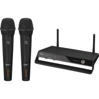
| Product type | Wireless audio transmission system (microphone + receiver) |
| Brand | IMG STAGE LINE |
| Model | ATS20R |
| Radio frequency | 863–865 MHz, 16 channels |
| Range | Approx. 50 m |
| Power supply | 2 NiMH rechargeable batteries 1.2 V (supplied) or 2 R6 batteries 1.5 V or 5 V power adapter (not supplied) |
| Dimensions (transmitter/receiver) | 66 × 111 × 35 mm (each) |
| Weight (transmitter) | 85 g (without batteries) |
| Weight (receiver) | 100 g (without batteries) |
| Internal microphone | Yes, on transmitter (disconnected when MIC or AUX IN jack is plugged) |
| External microphone input | 3.5 mm mono jack (MIC socket) |
| Line input | 3.5 mm mono jack (AUX IN) on transmitter |
| Line output | 3.5 mm stereo jack (AUX OUT) on receiver |
| Headphone output | 3.5 mm jack (EAR.) on receiver |
| Internal speaker | Yes, on receiver |
| Operating temperature | 0–40 °C |
| Cleaning | Dry soft cloth, no chemicals or water |
| Safety | Indoor use only; remove batteries if not used for a long time; do not expose to moisture or excessive heat |
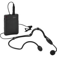
| Included accessories | Electret lavalier microphone, earphone ES-16, 2 NiMH rechargeable batteries per device, belt clip |
| Optional accessories | Charging station ATS-16PS, charging case ATS-36C, microphone ECM-16N, sound tube ET-16, pouch ATS-16BAG, cable ATS-16CORD |
| Repairability | User replaceable batteries/rechargeable batteries; for other repairs, contact an authorized service |
Frequently Asked Questions - ATS20R IMG STAGE LINE
User questions about ATS20R IMG STAGE LINE
0 question about this device. Answer the ones you know or ask your own.
Ask a new question about this device
Download the instructions for your Microphone in PDF format for free! Find your manual ATS20R - IMG STAGE LINE and take your electronic device back in hand. On this page are published all the documents necessary for the use of your device. ATS20R by IMG STAGE LINE.