FXBAR5SET - Effect machine IMG STAGE LINE - Free user manual and instructions
Find the device manual for free FXBAR5SET IMG STAGE LINE in PDF.
| Product type | Effect machine (light set) |
| Brand | IMG STAGE LINE |
| Model | FXBAR5SET |
| Total weight | 11 kg |
| Power supply | 230 V / 50 Hz |
| Power consumption | 85 VA max. |
| DMX protocol | DMX 512, 3/5/9/27 channels |
| LED projectors | 2 LED projectors 3×3W RGB, 13° angle |
| LED Derby projectors | 2 LED projectors 1×6W RGB |
| Strobe LEDs | 4 white LEDs 1W, 8° angle |
| Laser | Class 2M, red 100mW/650nm, green 30mW/532nm |
| Wireless control | Wireless footswitch 434 MHz, infrared remote control |
| Operating mode | Standalone, Master/Slave, DMX |
| Operating temperature | 0 – 40 °C |
| Stand height included | 1.45 – 2.4 m (adjustable) |
| Maintenance | Clean lenses with glass cleaner, housing with soft cloth |
| Safety | Do not look at the laser beam, disconnect before cleaning |
| Repairability | Repairs by qualified technician only |
Frequently Asked Questions - FXBAR5SET IMG STAGE LINE
User questions about FXBAR5SET IMG STAGE LINE
0 question about this device. Answer the ones you know or ask your own.
Ask a new question about this device
Download the instructions for your Effect machine in PDF format for free! Find your manual FXBAR5SET - IMG STAGE LINE and take your electronic device back in hand. On this page are published all the documents necessary for the use of your device. FXBAR5SET by IMG STAGE LINE.
USER MANUAL FXBAR5SET IMG STAGE LINE
with LED Spotlights / LED Derby Lights and Laser Unit

FXBAR-5SET
4.2 Festinstallation
roter Laser: .100 mW/650 nm
gruner Laser: 30 mW/532 nm
Allgemeine Daten
Sendefrequency: .434MHz
Pedale: .Auto, Music, Color, Blackout

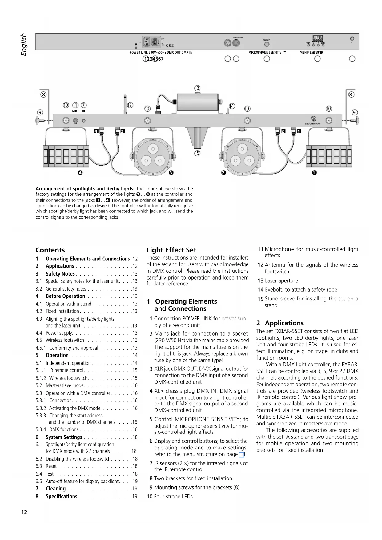
Arrangement of spotlights and derby lights: The figure above shows the factory settings for the arrangement of the lights 1...4 at the controller and their connections to the jacks 1...4. However, the order of arrangement and connection can be changed as desired. The controller will automatically recognize which spotlight/derby light has been connected to which jack and will send the control signals to the corresponding jacks.
Contents
1 Operating Elements and Connections 12
2 Applications 12
3 Safety Notes. 13
3.1 Special safety notes for the laser unit. 13
3.2 General safety notes 13
4 Before Operation 13
4.1 Operation with a stand. 13
4.2 Fixed installation 13
4.3 Aligning the spotlights/derby lights and the laser unit 13
4.4 Power supply. 13
4.5 Wireless footswitch 13
4.5.1 Conformity and approval 13
5 Operation 14
5.1 Independent operation. 14
5.1.1 IR remote control. 15
5.1.2 Wireless footswitch.. 15
5.2 Master/slave mode. 16
5.3 Operation with a DMX controller 16
5.3.1 Connection. 16
5.3.2 Activating the DMX mode 16
5.3.3 Changing the start address and the number of DMX channels 16
5.3.4 DMX functions 16
6 System Settings 18
6.1 Spotlight/Derby light configuration for DMX mode with 27 channels. . . . . . .18
6.2 Disabling the wireless footswitch. 18
6.3 Reset 18
6.4 Test 18
6.5 Auto-off feature for display backlight. 19
7 Cleaning 19
8 Specifications 19
Light Effect Set
These instructions are intended for installers of the set and for users with basic knowledge in DMX control. Please read the instructions carefully prior to operation and keep them for later reference.
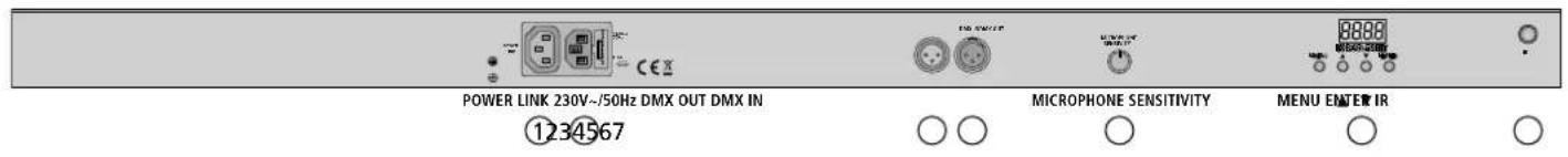
1 Operating Elements and Connections
1 Connection POWER LINK for power supply of a second unit
2 Mains jack for connection to a socket (230V / 50Hz) via the mains cable provided The support for the mains fuse is on the right of this jack. Always replace a blown fuse by one of the same type!
3 XLR jack DMX OUT: DMX signal output for connection to the DMX input of a second DMX-controlled unit
4 XLR chassis plug DMX IN: DMX signal input for connection to a light controller or to the DMX signal output of a second DMX-controlled unit
5 Control MICROPHONE SENSITIVITY; to adjust the microphone sensitivity for music-controlled light effects
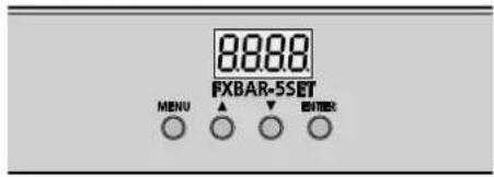
6 Display and control buttons; to select the operating mode and to make settings, refer to the menu structure on page 14
7 IR sensors (2×) for the infrared signals of the IR remote control
8 Two brackets for fixed installation
9 Mounting screws for the brackets (8)
0 Four strobe LEDs
11 Microphone for music-controlled light effects
12 Antenna for the signals of the wireless footswitch
13 Laser aperture
14 Eyebolt; to attach a safety rope
15 Stand sleeve for installing the set on a stand
2 Applications
The set FXBAR-5SET consists of two flat LED spotlights, two LED derby lights, one laser unit and four strobe LEDs. It is used for effect illumination, e.g. on stage, in clubs and function rooms.
With a DMX light controller, the FXBAR-5SET can be controlled via 3, 5, 9 or 27 DMX channels according to the desired functions. For independent operation, two remote controls are provided (wireless footswitch and IR remote control). Various light show programs are available which can be music-controlled via the integrated microphone. Multiple FXBAR-5SET can be interconnected and synchronized in master/slave mode.
The following accessories are supplied with the set: A stand and two transport bags for mobile operation and two mounting brackets for fixed installation.
3 Safety Notes
The set corresponds to all relevant directives of the EU and is therefore marked with
3.1 Special safety notes for the laser unit
The laser unit features class 2M lasers. The laser diodes have the following power and wavelengths:
| Power Wavelength | ||
| green laser | 30 mW 532 nm | |
| red laser 100 mW 650 nm | ||
WARNING 1.
Do not stare into the beam! A short-period exposure (0.25 seconds max.) to the laser beam, however, is not hazardous to the eye.
- Do not view the laser beam with optical instruments (e.g. magnifier or telescope); the retina may be permanently damaged.
- Never point the laser beam at the eyes of persons or animals. Be aware of beam reflections on shiny surfaces; make sure that reflections of the laser beam do not hit the eye.
- Do not open or modify the unit. Any modification may result in a more hazardous laser radiation (higher laser class).
- Never leave the laser unit unattended during operation.
3.2 General safety notes
WARNING
The set uses dangerous mains voltage. Leave servicing to skilled personnel and do not insert anything into the air vents. Inexpert handling may result in electric shock.
The set is suitable for indoor use only. Protect it against dripping water, splash water and high air humidity. The admissible ambient temperature range is 0 - 40^
- Do not place any vessels filled with liquid, e.g. drinking glasses, on the unit.
- Immediately disconnect the mains plug from the socket
- if the set or the mains cable is visibly damaged,
-
if a defect might have occurred after the set was dropped or suffered a similar accident,
-
if malfunctions occur.
In any case the set must be repaired by skilled personnel.
- Never pull the mains cable to disconnect the mains plug from the socket, always seize the plug.
- No guarantee claims for the set and no liability for any resulting personal damage or
material damage will be accepted if the set is used for other purposes than originally intended, if it is not safely installed or not correctly connected or operated, or if it is not repaired in an expert way.

If the set is to be put out of operation definitively, take it to a local recycling plant for a disposal which is not harmful to the environment.
4 Before Operation
Install the set safely and expertly. From a legal point of view, the person setting up the unit with its additional components (e.g. mirrors, projection surface) to create a laser effect installation, is the manufacturer of this installation. Always observe the warning notes in chapter 3.1.
WARNING

Always observe the regulations of the country where the set is operated!
When installing the set at a place where people may walk or sit under it, use a safety rope to additionally secure the set. Attach the safety rope to the eyebolt (14) in such a way that the maximum falling distance of the set will not exceed 20cm .
Set up or install the FXBAR-5SET in such a way that sufficient air circulation will be ensured during operation. Always observe a minimum distance of 50~cm from the laser unit and the spotlights /derby lights to the projection surface. Never cover the air vents of the housing.
4.1 Operation with a stand
1) Place the stand on a horizontal, solid ground. For a safe position, spread the legs of the stand as far as possible and secure them with the locking screw.
2) Place the controller with the lights already installed onto the stand and secure it with the locking screw.
3) To adjust the desired height: Pull out the telescopic tube and put the safety pin through the two holes for the height desired, then slide back the tube until the safety pin rests on the outer tube. Use the knob screw to additionally secure the telescopic tube.
IMPORTANT!
- Make sure that the stand is stable. Only pull out the telescopic tube to such an extent that the stand cannot fall over.
- Prior to operation, check all locking screws and fasten them, if required.
- Lay the connection cables in such a way that nobody will trip over the cables and knock over the stand.
4.2 Fixed installation
For fixed installation to a wall or ceiling, find a suitable location for the two mounting brackets (8) and fasten them expertly. Use the knob screws provided (9) to fasten the controller to the brackets.
4.3 Aligning the spotlights/ derby lights and the laser unit
For aligning, unscrew the corresponding locking screws and turn/tilt the units in the desired direction. Make sure that the cables are neither squeezed nor stretched. Then fasten the screws again.
4.4 Power supply
Use the mains cable provided to connect the mains jack "230 V/50 Hz" (2) of the FX-BAR-5SET to a mains socket (230 V/50 Hz). The unit will be switched on. The display will briefly indicate the firmware version (e.g. U100) and the operating mode most recently selected.
When multiple FXBAR-5SET are used, use a mains cable with 3-pin IEC plug and 3-pin IEC inline jack (e.g. AAC-170/SW) to connect the jack POWER LINK (1) of the first unit to the mains jack (2) of the second unit. Connect the second unit to the third unit etc. until all units have been connected in a chain. Thus, up to 15 FXBAR-5SET can be interconnected.
The jack POWER LINK can also be used for power supply of other (light effect) units. However, the current load of the jacks POWER LINK and "230 V~/50 Hz" must not exceed 6.3 A; otherwise, overload may result in short circuit and fire. The fuse will not protect these jacks.
4.5 Wireless footswitch
When the wireless footswitch is used, unfold its transmitting antenna and the reception antenna (12) of the controller and put both antennas in a vertical position.
4.5.1 Conformity and approval
Herewith, MONACOR INTERNATIONAL declare that the wireless footswitch and the reception electronics of the light effect set FXBAR-5SET comply with the directive 2014/53/EU. The EU declaration of conformity is available on request from MONACOR INTERNATIONAL. The units are generally approved for operation in EU and EFTA countries; they are licence-free and require no registration.
5 Operation
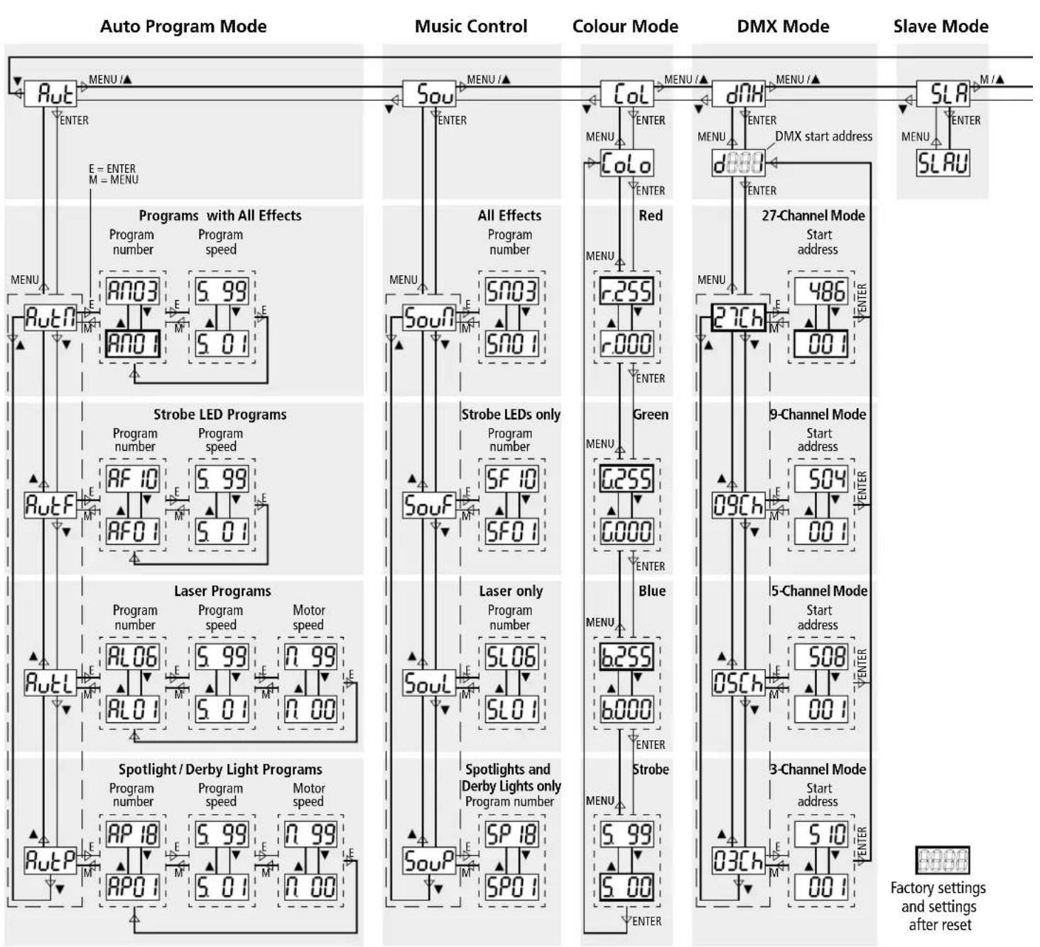
The control buttons MENU, , and ENTER are used to select the operating mode and to make various settings. The menu structure below shows how to select the modes and functions by means of these buttons.
Hint: Press the button MENU repeatedly to go to the highest menu level from any position in the menu and to select the operating mode without changing any settings.
5.1 Independent operation
For independent operation, the following modes are available:
Automatic show programs
Sou music-controlled show programs
Colour mode with the same adjustable colour for all spotlights and derby lights, with or without strobe effect
The menu structure gives an overview of the programs:
1) Press the button MENU repeatedly until the display indicates the desired mode. Rb, Sou or Col.
2) Press the button ENTER.
3) When the button ENTER is pressed repeatedly in the colour mode, all colours and the strobe function can be selected one after the other. Use the buttons and
to adjust the brightness of the colour or the strobe speed.
4) For the show programs, use the buttons and to select:
But! / Sou! = combination of all effects
= strobe LEDs only
Aul/Lsoul = laser only
HutP/ _ouP = spotlights and derby lights only
5) Press the button ENTER again and use the buttons and to select a program number.
6) For the automatic programs, press the button ENTER and then adjust the program speed (501...599).
For the laser programs and spotlight/ derby light programs, press the button
Menu Structure
ENTER again and then adjust the motor speed (n 00...n 99).
7) For the music-controlled programs, turn up the control MICROPHONE SENSITIVITY until the FXBAR-5SET responds to the music as desired. When the volume of the music system is changed, readjust the control accordingly. If there is no optimum music control although the control has been turned up very far, increase the volume or reduce the distance between the speakers and the FXBAR-5SET.
After 5 seconds, when no sound (music) has been registered, all units will switch off their light beams. As soon as sound is registered again, they will switch them on again.
8) To select another mode, start with step 1 again.

5.1.1 IR remote control

1) Before operating the remote control for the first time, remove the protective film from the battery holder. Thus, the remote control is ready for operation.
If the remote control is not used for a longer period of time, remove the battery as a precaution. It may leak and damage the remote control.
2) The remote control will not work in DMX mode or slave mode. In these modes, press the button MENU on the controller first until the display indicates Rut, Sout or Col.
3) When pressing a button on the remote control, always point the remote control at one of the two IR sensors (7) (figure on page 12). Make sure that there are no obstacles between the sensor and the remote control:
| Button | Function |
| ON/OFF | light beams on/off |
| AUTO | automatic programs RNO1...RNO3 with all effects* |
| MUSIC | music-controlled programs SNO1...SNO3 with all effects* |
| A | spotlight/derby light programs* |
| B | laser programs* |
| C | strobe LED programs* |
| switchover between automatic mode and music control for the spotlight/derby light programs, laser programs and strobe LED programs (buttons A-C) | |
| II | stop/start of program |
| colour mode: all spotlights and derby lights emit light of the same colour Use the buttons to select the colours one after the other. | |
| 0...9 | speed of automatic programs |
| no function | |
| *Press the button again to go to the next program number. | |
Replacing the battery
1) Push the latch of the battery holder to the right (arrow 1) and pull out the holder (arrow 2).

2) Remove the discharged battery and insert a new battery (3V button cell, type CR2025) into the support, positive pole facing upwards.
3) Push the holder back into the remote control.
Please observe the note on disposal of batteries at the end of the following chapter.
5.1.2 Wireless footswitch

1) Before operating the footswitch for the first time, insert the 12V battery provided, refer to paragraph below.
2) Unfold the transmitting antenna of the footswitch and the reception antenna (12) of the controller and put both antennas in a vertical position.
Make sure that the footswitch mode is enabled (chapter 6.4). The footswitch mode is enabled in the factory and after reset.
3) Use the switch "I O" on the rear to switch on the footswitch.
4) The footswitch will not work in DMX mode or slave mode. In these modes, press the button MENU on the controller first until the display indicates Rut Sou or Col
5) The following functions can be controlled with the footswitch:
| Pedal | Function |
| AUTO | automatic show programsPress the button again to go to the next program number. |
| MUSIC | music-controlled show programsPress the button again to go to the next program number. |
| COLOR | colour mode: all spotlights and derby lights will emit light of the same colourPress the button again to go to the next colour: white - red - green - blue - yellow - cyan - purple - white etc. |
| BLACKOUT | light beams on/off |
Remember to switch off the footswitch after operation to prevent unnecessary discharge of the battery. If the footswitch is not used for a longer period of time, remove the battery as a precaution. It may leak and damage the footswitch.
Inserting/Replacing the battery
1) Unscrew the battery compartment cover on the lower side of the footswitch.
2) Replace the discharged battery.
3) Insert a new 12V battery (type 23AE) as indicated in the compartment.
4) Close the battery compartment and screw on the cover.

5.2 Master/slavemode
Multiple FXBAR-5SET can be synchronized. In this mode, one unit (master unit) will control the other units (slave units).
1) Connect the units to each other in a chain; refer to chapter 5.3, but skip step 1.
2) Set all slave units to slave mode: Press the button MENU repeatedly until the display indicates Sben press the button ENTER; the display will indicate SLAU
As long as a slave unit does not receive any control signal from the master unit, its display will flash.
3) Select the desired operating mode on the master unit (chapter 5); the slave units will follow accordingly.
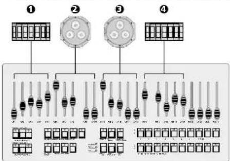
5.3 Operation with a DMX controller
For operation via a DMX light controller (e.g. DMX-1440 or DMX-510USB), the FXBAR-5SET is equipped with 27 DMX control channels. The FXBAR-5SET can also be controlled via 9, 5 or 3 channels if the functions provided are sufficient (6 chapter 5.3.3) or if the number of channels available on the light controller is less than 27.
5.3.1 Connection

For DMX signal transmission, special cables are recommended (e.g. cables of the CDMNX series). For cable lengths exceeding 150 m or when controlling more than 32 units via a single DMX output, it is generally recommended to insert a DMX level matching amplifier (e.g. SR-103DMX).
1) Connect the input DMX IN to the DMX output of the light controller or to the DMX output of a second DMX-controlled unit.
2) Connect the output DMX OUT to the DMX input of the second DMX unit. Proceed in the same way to connect the output of the second unit to the input of the third unit etc. until all DMX-controlled units have been connected in a chain.
3) To prevent interference in signal transmission, in case of long cables or a multitude of units connected in series, terminate the DMX output of the last DMX unit in the chain with a 120 resistor (>0.3W) : Connect a corresponding terminating plug (e.g. DLT-123) to the DMX output jack.
5.3.2 Activating the DMX mode
For separate control of all DMX units connected to the light controller, each unit must have its own start address. For FXBAR-5SET, start address 1 and control via 27 DMX channels are factory-set. If start address 1 is already used for another DMX-controlled unit, change the start address of the FXBAR-5SET. To change the start address and the number of DMX channels, refer to the chapter below.
To activate the DMX mode, press the button MENU repeatedly until the display indicates dH. Then press the button ENTER. The display will indicate the start address (e.g. 500). The FXBAR-5SET can now be controlled via DMX. If the set does not receive any control signal, the start address will flash.
5.3.3 Changing the start address and the number of DMX channels
1) Activate the DMX mode so that the display indicates the DMX start address (refer to previous paragraph).
2) Press the button ENTER once again so that the number of DMX channels is indicated.
3) Use the button or to select the number of DMX channels.
4) Press the button ENTER again: The start address will be indicated.
5) To change the start address, press the button or .
6) To save the settings, finally press the button ENTER once again. The display will indicate "d" and the start address.
| Examples of settings | |||
| Number of DMX channels | Start address | Addresses used by FXBAR-5SET | Next possible start address for next DMX unit |
| 3 | 1 | 1-3 | 4 |
| 6 | 6-8 | 9 | |
| 5 | 1 | 1-5 | 6 |
| 8 | 8-12 | 13 | |
| 9 | 1 | 1-9 | 10 |
| 24 | 24-32 | 33 | |
| 27 | 1 | 1-27 | 28 |
| 486 | 486-512 | - | |
=Factory settings and settings after reset
5.3.4 DMX functions
| 3-channel modeshow program only | |||
| DMX chan- nel | DMX value set in chan- nel 1 | DMX value | Function |
| 1 | — | 000-009 | blackout (all light beams off) |
| Preselection of program | |||
| 010-031 | spotlight/derby light programs | ||
| 032-065 | laser programs | ||
| 066-095 | strobe LED programs | ||
| 096-127 | programs with all effects | ||
| 128-159 | music-controlled spotlights and derby lights | ||
| 160-191 | music-controlled laser beams | ||
| 192-223 | music-controlled strobe LEDs | ||
| 224-255 | music control of all effects | ||
| Automatic programs | |||
| 2 | 010 ...031 | 000-009 | RPO1 |
| 010-019 | RPO2 | ||
| 020-029 | RPO3 | ||
| 030-039 | RPO4 | ||
| 040-049 | RPO5 | ||
| 050-059 | RPO6 | ||
| 060-069 | RPO7 | ||
| 070-079 | RPO8 | ||
| 080-089 | RPO9 | ||
| 090-099 | RPT0 | ||
| 100-109 | RPT1 | ||
| 110-119 | RPT2 | ||
| 120-129 | RPT3 | ||
| 130-139 | RPT4 | ||
| 140-149 | RPT5 | ||
| 150-159 | RPT6 | ||
| 160-169 | RPT7 | ||
| 170-255 | RPT8 | ||
| 032 ...065 | 000-039 | RLO1 | |
| 040-079 | RLO2 | ||
| 080-119 | RLO3 | ||
| 120-139 | RLO4 | ||
| 140-159 | RLOS | ||
| 160-255 | RLOS | ||
| 066 ...095 | 000-014 | RFOT1 | |
| 015-029 | RFOT2 | ||
| 030-044 | RFOT3 | ||
| 045-059 | RFOT4 | ||
| 060-074 | RFOS | ||
| 075-089 | RFOS | ||
| 090-104 | RFOT1 | ||
| 105-119 | RFOT8 | ||
| 120-134 | RFOT9 | ||
| 135-255 | RFTO | ||
| 096 ...127 | 000-019 | RFOT1 | |
| 020-039 | RFOT2 | ||
| 040-255 | RFOT3 | ||
| 3-channel modecontinued | |||
| DMX chan- nel | DMX value set in chan- nel 1 | DMX value | Function |
| Music-controlled programs | |||
| 2 | 128 ... 159 | 000-009 | SP01 |
| 010-019 | SP02 | ||
| 020-029 | SP03 | ||
| 030-039 | SP04 | ||
| 040-049 | SP05 | ||
| 050-059 | SP06 | ||
| 060-069 | SP07 | ||
| 070-079 | SP08 | ||
| 080-089 | SP09 | ||
| 090-099 | SP10 | ||
| 100-109 | SP11 | ||
| 110-119 | SP12 | ||
| 120-129 | SP13 | ||
| 130-139 | SP14 | ||
| 140-149 | SP15 | ||
| 150-159 | SP16 | ||
| 160-169 | SP17 | ||
| 170-255 | SP18 | ||
| 160 ... 191 | 000-039 | SL01 | |
| 040-079 | SL02 | ||
| 080-119 | SL03 | ||
| 120-139 | SL04 | ||
| 140-159 | SL05 | ||
| 160-255 | SL06 | ||
| 192 ... 223 | 000-014 | SFO1 | |
| 015-029 | SFO2 | ||
| 030-044 | SFO3 | ||
| 045-059 | SFO4 | ||
| 060-074 | SFO5 | ||
| 075-089 | SFO6 | ||
| 090-104 | SFO7 | ||
| 105-119 | SFO8 | ||
| 120-134 | SFO9 | ||
| 135-255 | SF10 | ||
| 224 ... 255 | 000-019 | SNO1 | |
| 020-039 | SNO2 | ||
| 040-255 | SNO3 | ||
| 3 | 010 ... 127 | 000-255 | program speedslow→fast |
| 5-channel mode same lighting colour for all spotlights and derby lights, no laser, no strobe LEDs | |||
| Effect unit | DMX channel | DMX value | Function |
| Spot-lights 2 + 3 | 100 | -255 basic brightness of red | |
| 2 | 000 - 255 basic brightness of green | ||
| 3 | 000 - 255 basic brightness of blue | ||
| derby lights 1 + 4 | 4 | 000 - 191 total brightness, channels 1 - 3 | |
| 192 - 200 music-controlled strobe | |||
| 201 - 249 strobe slow → fast | |||
| 250 - 255 all colours at max. brightness | |||
| Derby lights 1 + 4 | 5 | 000 - 004 no rotation | |
| 005 - 127 rotation ∅ slow → fast | |||
| 128 - 133 no rotation | |||
| 134 - 255 rotation ∅ slow → fast | |||
| 9-channel mode same lighting colour for all spotlights and derby lights, with laser effects and strobe LED effects | |||
| Effect unit | DMX chan- nel | DMX value | Function |
| Spot- lights 2+3 and derby lights 1+4 | 100-255 basic brightness of red | ||
| 2 | 000-255 basic brightness of green | ||
| 3 | 000-255 basic brightness of blue | ||
| 4 | 000-191 total brightness, channels 1-3 | ||
| 192-200 music-controlled strobe | |||
| 201-249 strobe slow → fast | |||
| 250-255 all colours at max. brightness | |||
| Derby lights 1+4 | 5 | 000-004 no rotation | |
| 005-127 rotation ∪ slow→fast | |||
| 128-133 no rotation | |||
| 134-255 rotation ∪ slow→fast | |||
| Laser unit | 6 | 000-004 red laser off | |
| 005-009 red laser on | |||
| 010-255 red laser flashing slow→fast | |||
| 7 | 000-004 green laser off | ||
| 005-009 green laser on | |||
| 010-255 green laser flashing slow→fast | |||
| 8 | 000-004 no rotation | ||
| 005-127 rotation ∪ slow→fast | |||
| 128-133 no rotation | |||
| 134-255 rotation ∪ slow→fast | |||
| Strobe LEDs | 9 | 000-004 strobe LEDs off | |
| 005-009 strobe LEDs on | |||
| 010-255 strobe slow→fast | |||
| 27-channel mode separate control of all effect units, no show programs | |||
| Effect unit | DMX chan- nel | DMX value | Function |
| Derby light ➀ | 1 000-255 brightness of red | ||
| 2 | 000-255 brightness of green | ||
| 3 | 000-255 brightness of blue | ||
| 4 | 000-009 no strobe | ||
| 010-255 strobe slow→fast | |||
| 5 | 000-004 no rotation | ||
| 005-127 rotation ∪ slow→fast | |||
| 128-133 no rotation | |||
| 134-255 rotation ∪ slow→fast | |||
| Spot- light ➁ | 6 | 000-255 brightness of red | |
| 7 | 000-255 brightness of green | ||
| 8 | 000-255 brightness of blue | ||
| 9 | 000-009 no strobe | ||
| 010-255 strobe slow→fast | |||
| 10 | no function* (spare channel for rotation) | ||
| Spot- light ➁ | 11 000-255 brightness of red | ||
| 12 | 000-255 brightness of green | ||
| 13 | 000-255 brightness of blue | ||
| 14 | 000-009 no strobe | ||
| 010-255 strobe slow→fast | |||
| 15 | no function* (spare channel for rotation) | ||
| Derby light ➁ | 16 000-255 brightness of red | ||
| 17 | 000-255 brightness of green | ||
| 18 | 000-255 brightness of blue | ||
| 19 | 000-009 no strobe | ||
| 010-255 strobe slow→fast | |||
| 20 | 000-004 no rotation | ||
| 005-127 rotation ∪ slow→fast | |||
| 128-133 no rotation | |||
| 134-255 rotation ∪ slow→fast | |||
| Laser | 21 | 000-004 red laser off | |
| 005-009 red laser on | |||
| 010-255 red laser flashing slow→fast | |||
| 22 | 000-004 green laser off | ||
| 005-009 green laser on | |||
| 010-255 green laser flashing slow→fast | |||
| 23 | 000-004 no rotation | ||
| 005-127 rotation ∪ slow→fast | |||
| 128-133 no rotation | |||
| 134-255 rotation ∪ slow→fast | |||
| Strobe LED 1 | 24 | 000-004 off | |
| 005-009 on | |||
| 010-255 strobe slow→fast | |||
| Strobe LED 2 | 25 | 000-004 off | |
| 005-009 on | |||
| 010-255 strobe slow→fast | |||
| Strobe LED 3 | 26 | 000-004 off | |
| 005-009 on | |||
| 010-255 strobe slow→fast | |||
| Strobe LED 4 | 27 | 000-004 off | |
| 005-009 on | |||
| 010-255 strobe slow→fast | |||
- If a derby light has been connected to the jack 2 and/or 1 and the menu item changed accordingly (chapter 6.1), the rotation will be adjustable via channel 10 and /or 15; for DMX values refer to channel 5 or 20.
6 System Settings
The following system settings can be changed via menu item:
6.1 Spotlight/Derbylight configuration
for DMX mode with 27 channels
It is not necessary to change the setting for the spotlight /derby light configuration unless the arrangement of lights has been changed and DMX control of the FXBAR-5SET with 27 channels is desired.
The controller will automatically recognize which spotlight/derby light (1...4) has been connected to which jack (1...4) and will send the control signals to the corresponding jacks. The number can be found on the rear of the light and in the figure on page 14. For the 27-channel mode, this means:
| light number | will be controlled via the DMX channels |
| 1 | 1 - 5 |
| 2 | 6 - 10 |
| 3 | 11 - 15 |
| 4 | 16 - 20 |
If the arrangement of the spotlights /derby lights has not been changed, the controls for the lights on the light controller will be in the same order as the lights at the controller:
Example 1: Factory-set arrangement
If the arrangement of the spotlights /derby lights has been changed, automatic redirection of the control signals will result in a different order. In the following example, the lights 2 and 4 have been interchanged:

Example 2: Order of the controls when the arrangement has been changed and the system settings remain the same
If the arrangement of the spotlights/derby lights has been changed and the order of the controls is to be the same as the order of the lights, change the settings of the menu item [dd5]
1) Press the button MENU to select the menu item [555] Press the button ENTER. The display will indicate the submenu item most recently selected.
2) Use the button or to select the submenu item AddS. Press the button ENTER. The display will indicate the configuration:

3) The digit on the left starts flashing, i.e. channel group 1 has been selected. Press the button to select the groups one after the other.
4) To be able to control a different spotlight/ derby light with a channel group, press the button repeatedly until the number of the corresponding light is indicated on the display.

Example:
Example 3: Order of the controls when the arrangement of the spotlights/derby lights and the system settings have been changed
5) Finally press the button ENTER to save the settings.
6.2 Disabling the wireless footswitch
In the factory settings, the wireless footswitch mode is enabled. To disable the footswitch mode when the footswitch is not required or when the FXBAR-5SET changes the mode inadvertently (e.g. due to interference signals):
1) Press the button MENU to select the menu item [595] Press the button ENTER. The display will indicate the submenu item most recently selected.
2) Use the button or to select the submenu item B-En. Press the button ENTER. The display will indicate the current setting.
3) Use the button or to enable (on) or disable (off) the footswitch mode. Press the button ENTER to save the setting.
6.3 Reset
The factory settings of the FXBAR-5SET can be found below. In the menu structure on page 14, the boxes containing the factory settings are printed in bold.
| Factory settings | ||
| Subject | Function | Setting |
| Show program mode | program number | program #no. with all effects |
| program speed | S. 80 | |
| Colour mode | brightness | red, green and blue at max. brightness (255) |
| stroboscope | off (S. 00) | |
| DMX | start address | 001 |
| number of channels | 27 | |
| System settings | spotlight/derby light configuration | 1 2 3 4 |
| wireless foot-switch mode | on | |
| auto-off feature for display backlight | off | |
Reset to the factory settings:
1) Press the button MENU to select the menu item 595. Press the button ENTER. The display will indicate the submenu item most recently selected.
2) Use the button or to select the submenu item Press the button ENTER. The display will briefly indicate the firmware version (e.g. 100 before the show program is selected.
6.4 Test
A test can be performed to check all LEDs, lasers and motors:
1) Press the button MENU to select the menu item 555. Press the button ENTER. The display will indicate the submenu item most recently selected.
2) Use the button or to select the submenu item ESE. Testing will start immediately:
- During the first 30s, the show programs will be tested. If music is picked up by the microphone, the programs will be music-controlled; if not, they will be executed automatically.
After 30s, the display will go to 8888. All LEDs and lasers will emit light at maximum brightness and all motors will run at maximum speed.
3) To exit the test, press the button MENU.
6.5 Auto-off feature for display backlight
If the brightness of the display backlight is inconvenient, this feature will automatically deactivate the backlight after 30 seconds when no button is pressed. Only a small dot will be illuminated. As soon as a button is pressed, the display backlight will be activated for 30 seconds again.
1) Press the button MENU to select the menu item. press the button ENTER. The display will indicate the submenu item most recently selected.
2) Use the button or to select the submenu item LEds. Press the button ENTER. The display will indicate the current setting.
3) Use the button or to activate (on) or deactivate (off) the auto-off feature. Press the button ENTER to save the setting.
7 Cleaning
Clean the lenses used for focussing the light beams at regular intervals (depending on impurities) to ensure that light will be radiated at maximum brightness. Always disconnect the mains plug from the socket before cleaning. Only use a soft clean cloth and a glass cleaner. Then wipe the lenses dry.
For cleaning the housing, only use a soft clean cloth. Never use any fluid; it may leak into the units and damage them.
8 Specifications
DMX
Data protocol: DMX 512
Number of channels: . . . 3, 5, 9 or 27
LED spotlights
Number: 2
LEDs of each spotlight: .3 RGB LEDs, 3 W each
Beam angle: 13°
LED derby lights
Number: 2
LED of each light: 1 RGB LED, 6 W
Strobe LEDs
Number: 4
Colour: .white
Power of each LED: 1W
Beam angle: .8°
Laser unit
Laser class: .2M
Power/Wavelength
red laser: 100 mW/650 nm
green laser: 30 mW/532 nm
General information
Power supply: 230V/50Hz
Power consumption: .85 VA max.
Ambient temperature: .0-40°C
Dimensions of controller
with effect units: 1170 × 310 × 150 mm
Total weight: 11 kg
IR remote control
Power supply: 3 V button cell, type CR 2025
Dimensions: 40 × 7 × 86 ~mm
Weight: 12g
Wireless footswitch
Transmitting frequency: .434MHz
Pedals: Auto, Music, Color, Blackout
Power supply: 12 V battery, type 23AE (1811A)
Dimensions: 420 × 43 × 150mm (without antenna)
Weight: 1.25 kg
Stand
Height (adjustable): 1.45 - 2.4 m, adjustable in 6 steps
Subject to technical modification.
5.1.2 Pedale wireless

4.2 Vaste installation
Rut/L SouL = alleen laser
rode laser: 100 mW/650 nm
groene laser: 30 mW/532 nm
Algemene gegevens
Voedingsspanning: 230V/50Hz
Vermogensopname: . max.85VA
Omgevings
Pedales: Auto, Music, Color, Blackout
Altura(regulable):1,45-2,4m
Pedaly: Auto, Music, Color, Blackout
Zasilanie: 12V bateria, typ 23AE (1811A)
Wymiary: 420 × 43 × 150 ~mm (bez antenna)
Waga: 1,25kg