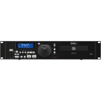
TXS2402SET - Microphone IMG STAGE LINE - Free user manual and instructions
Find the device manual for free TXS2402SET IMG STAGE LINE in PDF.
User questions about TXS2402SET IMG STAGE LINE
0 question about this device. Answer the ones you know or ask your own.
Ask a new question about this device
Download the instructions for your Microphone in PDF format for free! Find your manual TXS2402SET - IMG STAGE LINE and take your electronic device back in hand. On this page are published all the documents necessary for the use of your device. TXS2402SET by IMG STAGE LINE.
USER MANUAL TXS2402SET IMG STAGE LINE
natural_image
Black wireless router with two LIMG speakers and two external antennas (no visible text or symbols)TXS-2402SET
English ...... Page 7
Français .... Page 10
2-Channel Microphone System
These instructions are intended for users without any specific technical knowledge. Please read these instructions carefully prior to operating the unit and keep them for later reference.
All operating elements and connections described can be found on the fold-out page 3.
1 Operating Elements and Connections
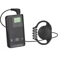
1.1 Receiver
1 Receiving antennas
2 On/off switch (keep it pressed for approx. 1 s), lights up as a power indication
3 Connection indicators, one each for MIC 1 and MIC 2
4 VOLUME controls, one each for MIC 1 and MIC 2
5 Momentary pushbutton RESET to reset the radio connection for the first channel (for service only)
6 Signal output for the mixed signal of both microphones: 6.3 mm jack, unbalanced
7 Momentary pushbutton RESET to reset the radio connection for the second channel (for service only)
8 Power supply jack for connection of the supplied power supply unit
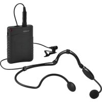
1.2 Microphone
9 On/offswitch
– lights up as a power indication
- flashes if the batteries are low
to switch off, keep it pressed for a while
10 Area of the transmitting antenna; do not cover during operation!
Rear side with the battery compartment opened
11 Rotary switch to select the transmission channel
12 Batteries in the battery compartment
2 Safety Notes
The units (wireless microphones, receiver and power supply unit) correspond to all relevant directives of the EU and are therefore marked with C€
WARNING
The power supply unit is supplied with hazardous mains voltage. Leave servicing to skilled personnel only. Inexpert handling or modification of the unit may cause an electric shock hazard.
- The units are suitable for indoor use only. Protect them against dripping water and splash water, high air humidity, and heat (admissible ambient temperature range 0–40°C).
- Do not set the receiver into operation, and immediately disconnect the power supply unit from the mains socket if
- there is visible damage to the units,
- a defect might have occurred after a drop or similar accident,
- malfunctions occur.
The units must in any case be repaired by skilled personnel. - For cleaning only use a dry, soft cloth, never use chemicals or water.
- No guarantee claims for the units and no liability for any resulting personal damage or material damage will be accepted if the units are used for other purposes than originally intended, if they are not correctly connected or operated, or if they are not repaired in an expert way.

If the units are to be put out of operation definitively, take them to a local recycling plant for a disposal which is not harmful to the environment.
3 Application
The TXS-2402SET is an easy-to-use 2-channel wireless microphone system consisting of two hand-held microphones and a receiver. It is suitable for versatile applications, e.g. for presentations, discussions or karaoke. The microphone signals are digitally transmitted with low interference on 2 of 16 selectable channels in the 2.4 GHz range. Two receivers with four microphones can be used at the same time.
3.1 Conformity and approval
Herewith, MONACOR INTERNATIONAL declare that the transmission system TXS-2402SET is in accordance with the basic requirements and the other relevant regulations of the directive 2014 / 53 / EU. The declaration of conformity available on request from MONACOR INTERNATIONAL.
The transmission system operates in the 2.4 GHz range and is licence-free and generally approved for operation in the EU and EFTA countries.
4 Setting into Operation
1) Set up the receiver (the height at which the microphones are held is ideally suited) and set up the two antennas (1) in a vertical position.
2) Connect the output of the receiver OUTPUT (6) to a line input of the following unit (e. g. mixer, amplifier). The 6.3 mm jack is unbalanced and supplies the mixed signal of both microphone channels. For connection, the supplied cable may be used.
3) For power supply of the microphones, move the cover of the battery compartment on the rear side of the microphones in direction of the microphone head and take it off. Insert two (rechargeable) batteries of size AA into the battery compartment, as shown in the battery compartment and in fig. 4.
Close the battery compartment with the cover.

Never put discharged batteries or defective rechargeable batteries in the household waste; always take them to a special waste disposal, e. g. collection container at your retailer.
4) Connect the supplied power supply unit to the power supply jack (8) on the receiver and to a socket (230 V/ 50 Hz).
5 Operation
1) Prior to switching-on for the first time, turn back the VOLUME controls (4) on the receiver to "1" for both microphones.
2) Switch on the receiver: keep the button ⏻ (2) pressed for approx. 1 s until it lights up.
3) Switch on one or two microphones with the button ⏻(9). The button lights up during operation. If it fails to light up or if it starts flashing, the batteries may be low and should be replaced.
After switching on a microphone, a wireless connection to the receiver is made. The LED (3) on the receiver indicates that a connection to the corresponding microphone has been established. If an LED fails to light up or starts flickering although the respective microphone has been switched on, the other microphone or another unit may cause interference in transmission. In this case, change the transmission channel of the microphone (chapter 5.1).
If there is still interference in transmission, please check
- if the batteries in the microphone are low.
- if there are objects or other wireless transmitters (e. g. microwaves, WLAN, baby monitors) in the transmission path which may interfere with reception. Metal objects in the vicinity of the transmitter or receiver may affect the directivity of the antenna.
- if the reception can be improved when you turn the antennas.
- if the distance between transmitter and receiver is too long (range approx. 20 m in buildings or 30 m in the open air).
4) Speak or sing into the microphone. Do not cover the area of the transmitting antenna (10), as this will reduce the range. Adjust the desired volume for both microphones with the VOLUME controls (4).
5) To switch off a microphone, keep the button ⏻ (9) pressed until the button stops lighting. To avoid unnecessary battery consumption, the microphone will switch off automatically after 5 minutes when nobody speaks into the microphone.
6) After operation switch off the receiver: keep the button ⬆(2) pressed for approx. 1 s until it stops lighting. The power supply unit has a low power consumption even when the receiver is switched off; therefore disconnect the power supply unit from the socket when the receiver is not used for a longer period of time.
5.1 Changing the transmission channel
If the transmission of a microphone is interfered by another unit [sound interruptions occur or the corresponding LED (3) flickers], the transmission frequency may be changed. 16 transmission channels are available.
1) Move the cover of the battery compartment on the rear side of the microphones in direction of the microphone head and take it off.
2) Use a small screwdriver to turn the rotary switch (11) to a different position. When the microphone and the receiver are switched on, it is possible to check the new connection immediately by means of the LED (3).
To prevent mutual interference of both microphones, a minimum distance of 2 channels must be adjusted. The optimum distance is 8 channels (i. e. the rotary switches of both microphones point exactly to the opposite direction).
6 Specifications
Carrier frequency range: .2404–2476 MHz, 16 channels
Transmitting power: . . . . 10 mW
Range: .....20 m (in buildings), 30 m (in the open air)
Audio frequency range: ..80 – 12 000 Hz
THD: ....< 0.1 %
Dynamic range: .....87 dB
Microphone cartridge
system: . . . . . . . . . dynamic
directivity: . . . . . . . . .supercardioid
max. SPL: .....115 dB
Audio output: .....100 mV, unbal., 6.3 mm jack
Ambient temperature
range: 0–40°C
Power supply
receiver: .....via supplied PSU connected to 230 V/50 Hz
microphone: .....2 × 1.5 V battery, size AA, operating time of approx. 26h
Dimensions, weight
receiver: .220 × 45 × 150 mm, 550 g
microphone: .....∅ 54 × 225 mm, 120g(w/obatteries)
Subject to technical modification.
Microphone : .....∅ 54 × 225 mm, 120 g (sans batteries)