USER MANUAL Robolinho 1150 AL-KO
natural_image
Line drawings of two different lawn covers (no text or symbols)


DE
GB
NL
FR
IT
SI
HR
RS
PL
CZ
SK
HU
DK
SE
NO
FI
RU
UA
Inhaltsverzeichnis
Deutsch 8
English....36
Nederlands 63
Français....91
Italiano 120
Slovenščina 148
Hrvatski....175
Српски....202
Polski 230
Česky 259
Slovenská 285
Magyarul....312
Dansk 340
Svensk 366
Norsk 391
Suomi 416
Русский 442
Україна 472
© 2020
AL-KO KOBER GROUP Kötz, Germany
This documentation or excerpts therefrom may not be reproduced or disclosed to third parties without the express permission of the AL-KO KOBER GROUP.
flowchart
graph TD
    A["1"] --> B["X0"]
    B --> C["i"]
    C --> D["h"]
    D --> E["X1"]
    E --> F["g"]
    F --> G["e"]
    G --> H["X5"]
    H --> I["x4"]
    I --> J["f"]
    J --> K["X3"]
    K --> L["d"]
    L --> M["c"]
    M --> N["X2"]
    N --> O["f"]
    O --> P["X2"]
    style A fill:#f9f,stroke:#333
    style P fill:#ccf,stroke:#333
11


Nr. Bauteil
Nr. Bauteil
Nr. Bauteil

1 About these operating instructions ..... 37
1.1 Symbols on the title page.... 37
1.2 Legends and signal words ...... 37
2 Product description ...... 37
2.1 Scope of supply.... 38
2.2 Automatic lawn mower 38
2.3 Symbols on the appliance 39
2.4 Control panel.... 39
2.5 Display 40
2.6 Menu structure 41
2.7 Base station 42
2.8 Rechargeable battery.... 42
2.9 Functional description 42
2.10 WLAN radio module and AL-KO in-TOUCH app 43
3 Safety.... 43
3.1 Intended use 43
3.2 Possible misuse 44
3.3 Safety and protective devices ..... 44
3.3.1 PIN and PUK input 44
3.3.2 Sensors 44
3.4 Safety instructions.... 45
3.4.1 Operator 45
3.4.2 Personal protective equipment .... 46
3.4.3 Safety of persons and animals .... 46
3.4.4 Appliance safety 46
3.4.5 Electrical safety 46
4 Assembly 47
4.1 Unpacking the machine...... 47
4.2 Planning the mowing areas (01) ..... 47
4.3 Preparing the mowing areas 47
4.4 Setting up the base station (03/a) ..... 47
4.5 Installing the boundary cable 48
4.5.1 Connecting the boundary cable to the base station (03/b).... 48
4.5.2 Routing the boundary cable (01) . 48
4.5.3 Excluding obstacles...... 48
4.5.4 Enclosing corridors (01/h) ...... 49
4.5.5 Excluding downward slopes (11). 49
4.5.6 Creating loops of cable (07)...... 49
4.5.7 Typical faults in cable routing (02).... 49
4.6 Connecting the base station to the power source (04).... 49
4.7 Checking the connections on the base station (04).... 49
5 Start-up.... 50
5.1 Charging the rechargeable battery (08) 50
5.2 Making the basic settings .... 50
5.3 Setting the cutting height 50
5.4 Carrying out an automatic calibration movement.... 50
6 Operation.... 51
6.1 Starting the appliance manually ..... 51
6.2 Cancelling mowing 51
6.3 Mowing the secondary area (01/NF) .. 51
7 Settings 51
7.1 Calling up the setting – General ..... 51
7.2 Activating/deactivating the button tones....52
7.3 Activating/deactivating Eco mode (Robolinho 700/1200/2000) .... 52
7.4 Setting the rain sensor (Robolinho 700/1200/2000) 52
7.5 Setting the mowing program.... 52
7.5.1 Setting the mowing program – General 52
7.5.2 Setting the start points ..... 52
7.5.3 Setting the mowing times.... 53
7.6 inTOUCH 53
7.7 Edge mowing with a manual start..... 54
7.8 Setting the secondary area mowing ... 54
7.9 Setting the display contrast ..... 54
7.10 Setting lock 54
7.11 Recalibrating.... 54
7.12 Restoring factory settings.... 54
8 Displaying information 54
9 Maintenance and care 55
9.1 Cleaning 55
9.2 Regular checks 55
9.3 Replacing the cutting blades ..... 55
10 Transport 56
11 Storage 56
11.1 Storing the automatic lawn mower ..... 56
11.2 Storing the charging pole 56
11.3 Winter storage of the boundary cable 56
12 Disposal 56
13 Help in case of malfunction.... 58
13.1 Correcting appliance and handling faults.... 58
13.2 Fault codes and troubleshooting ..... 59
14 After-Sales / Service 62
15 Guarantee....62
1 ABOUT THESE OPERATING INSTRUCTIONS
The German version is the original operating instructions. All additional language versions are translations of the original operating instructions.
■ Always safeguard these operating instructions so that they can be consulted if you need any information about the appliance.
■ Only pass on the appliance to other persons together with these operating instructions.
■ Comply with the safety and warning information in these operating instructions.
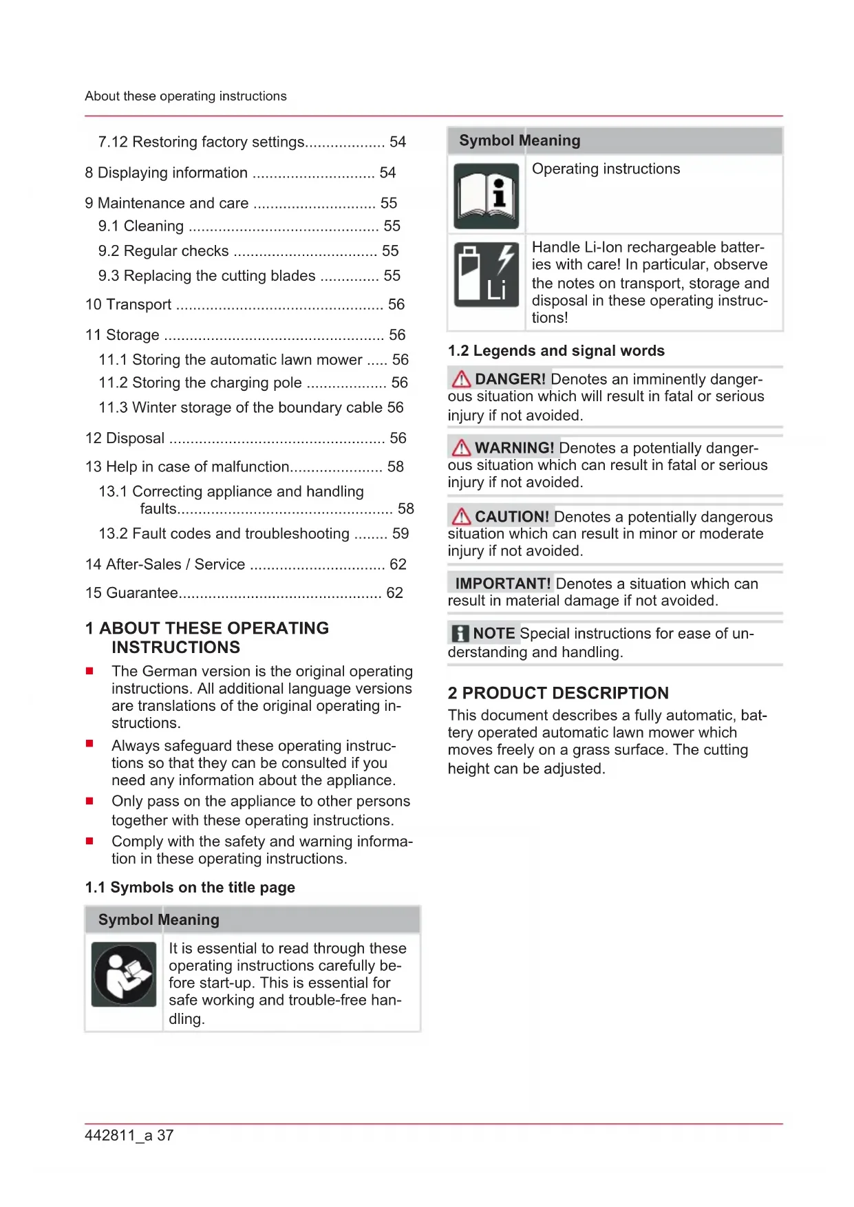
1.1 Symbols on the title page
Symbol Meaning

It is essential to read through these operating instructions carefully before start-up. This is essential for safe working and trouble-free handling.
Symbol Meaning

Operating instructions

Handle Li-Ion rechargeable batteries with care! In particular, observe the notes on transport, storage and disposal in these operating instructions!
1.2 Legends and signal words
⚠️ DANGER! Denotes an imminently dangerous situation which will result in fatal or serious injury if not avoided.
WARNING! Denotes a potentially dangerous situation which can result in fatal or serious injury if not avoided.
CAUTION! Denotes a potentially dangerous situation which can result in minor or moderate injury if not avoided.
IMPORTANT! Denotes a situation which can result in material damage if not avoided.
i NOTE Special instructions for ease of understanding and handling.
2 PRODUCT DESCRIPTION
This document describes a fully automatic, battery operated automatic lawn mower which moves freely on a grass surface. The cutting height can be adjusted.
2.1 Scope of supply
The items listed here are part of the scope of supply. Check that all items are included:
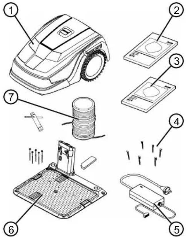
No. Component
| 1 Automatic lawn mower |
| 2 Quick-start guide |
| 3 Operating instructions |
| 4 Lawn pegs * |
| 5 Power supply |
| 6 Base station incl. screw nails (5 pcs.), wrench and winter cover |
| 7 Boundary cable ** |
* Robolinho 500: 90 pcs., Robolinho 1150: 180 pcs., Robolinho 700/1200/2000: Not included in the scope of delivery
** Robolinho 500: 100 m, Robolinho 1150: 150 m, Robolinho 700/1200/2000: Not included in the scope of delivery
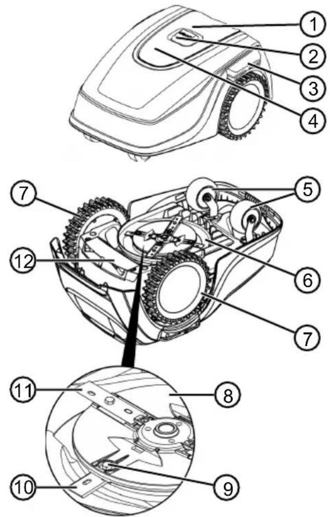
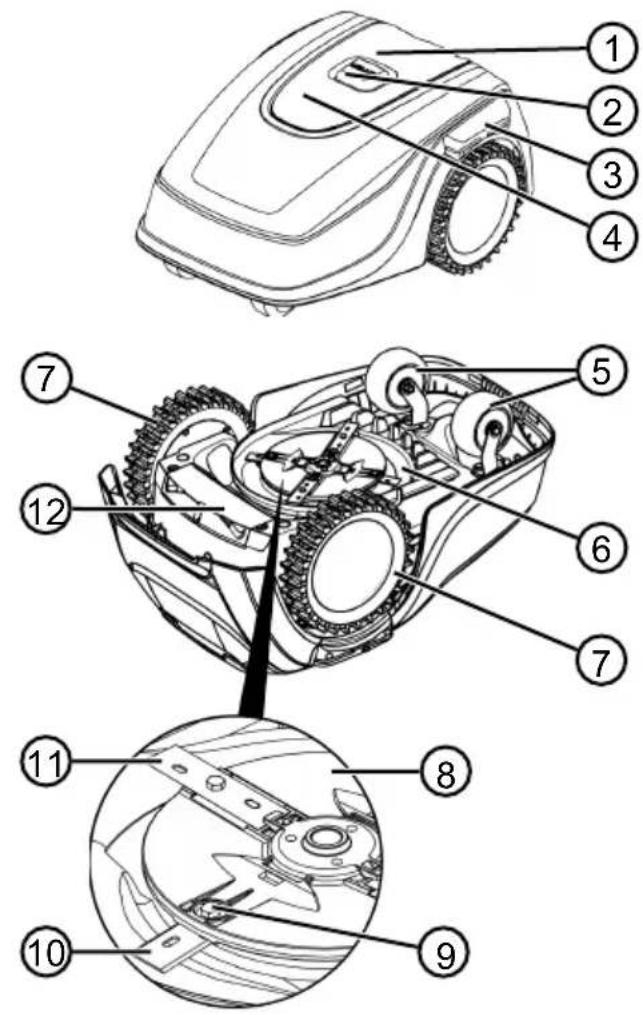
2.2 Automatic lawn mower

No. Component
| 1 Control panel with display (interior) |
| 2 STOP key (stops the appliance immediately and the cutting blade within 2 s) |
| 3 Charging contacts |
| 4 Height adjustment (interior) |
| 5 Front rollers (steering) |
| 6 Mower deck |
| 7 Drive wheel |
| 8 Blade plate |
| 9 Fastening screw |
| 10 Clearer blade |
| 11 Cutting blade |
| 12 Rechargeable battery compartment |
2.3 Symbols on the appliance
Symbol Meaning
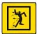
Keep other people out of the danger area!

Pay special attention when handling this product!
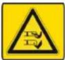
Keep your hands and feet away from the blade system!
Maintain a safety distance!
Read the operating instructions before starting operation!
Enter the PIN in order to start the appliance!

Do not ride on the appliance!
2.4 Control panel
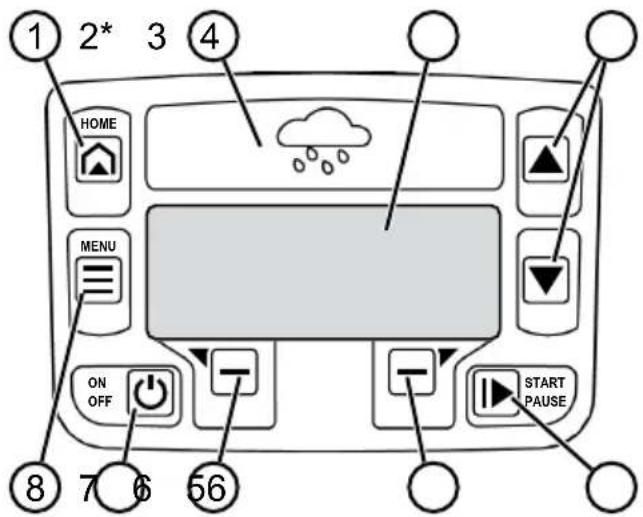
* Robolinho 700/1200/2000 only
No. Component
| 1 | [Gkx2] (home button): Cancel mowing, the appliance returns to its base station. It starts on the next day automatically again at the set mowing time. |
| 2 Rain sensor (Robolinho 700/1200/2000): Registers if it rains (see chapter 7.4 "Setting the rain sensor (Robolinho 700/1200/2000)", page 52). |
| 3 Display: Shows the current operating status of the appliance, the name of the selected menu, its menu items and the functions to be selected. (see chapter 2.5 "Display", page 40). |
| 4 |  arrow keys): Select the menu items, increase and decrease numerical values, select between settings. arrow keys): Select the menu items, increase and decrease numerical values, select between settings. |
| 5 | [▶] (start/pause button): Start mowing manually and stop mowing or immediately resume it again after pressing [IMAGE] |
| 6 | [—] function keys): Call up the function that is displayed directly above the button on the display. |
| 7 | [◀] (On/Off button): Switch the appliance on and off. |
| 8 | [≡] (menu button): Call up the main menu. |
(home button): Cancel mowing, the appliance returns to its base station. It starts on the next day automatically again at the set mowing time.
in sensor (Robolinho 700/1200/2000): Registers if it rains (see chapter 7.4 "Setting the rain sensor (Robolinho 700/1200/2000)", page 52).
splay: Shows the current operating status of the appliance, the name of the selected menu, its menu items and the functions to be selected. (see chapter 2.5 "Display", page 40).
2.5 Display
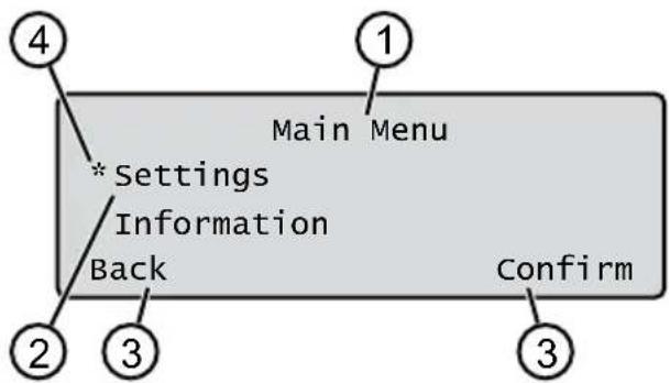
No. Display
1 Name of the selected menu (here: Main Menu)
2 Menu items in the menu: Only two menu items are ever displayed (here: Settings and Information). Further menu items can be displayed with ▲ and ▼
3 Functions for the selected menu item (here: Settings). Further functions can be called up with ▼ and . —
4 Asterisk for marking the displayed menu item (here: Settings)
2.6 Menu structure
| Main Menu | Programs | Weekly Program see chapter 7.5 "Setting the mowing program", page 52 |
| Entry Point see chapter 7.5.2 "Setting the start points", page 52 |
| Program Info see chapter 8 "Displaying information", page 54 |
| Settings | Time see chapter 5.2 "Making the basic settings", page 50 |
| Date see chapter 5.2 "Making the basic settings", page 50 |
| Language see chapter 5.2 "Making the basic settings", page 50 |
| PIN-Code see chapter 5.2 "Making the basic settings", page 50 |
| Key clicks see chapter 7.2 "Activating/deactivating the button tones", page 52 |
| EcoMode see chapter 7.3 "Activating/deactivating Eco mode (Robolin-ho 700/1200/2000)", page 52* |
| Rain sensorsee chapter 7.4 "Setting the rain sensor (Robolinho 700/1200/2000)", page 52* |
| After rain delay see chapter 7.4 "Setting the rain sensor (Robolinho 700/1200/2000)", page 52* |
| Rain sensitive see chapter 7.4 "Setting the rain sensor (Robolin-ho 700/1200/2000)", page 52* |
| inTOUCH see chapter 7.6 "inTOUCH", page 53 |
| Margin mowing see chapter 7.7 "Edge mowing with a manual start", page 54 |
| Sub zone active/disabled see chapter 7.8 "Setting the secondary area mowing", page 54 |
| Display contrast see chapter 7.9 "Setting the display contrast", page 54 |
| Safety settings see chapter 7.10 "Setting lock", page 54 |
| Reset calibration see chapter 7.11 "Recalibrating", page 54 |
| Factory reset see chapter 7.12 "Restoring factory settings", page 54 |
| Information | Blades service see chapter 8 "Displaying information", page 54 |
| Hardware see chapter 8 "Displaying information", page 54 |
| Software see chapter 8 "Displaying information", page 54 |
| Program Info see chapter 8 "Displaying information", page 54 |
| Failures see chapter 8 "Displaying information", page 54 |
* Robolinho 700/1200/2000
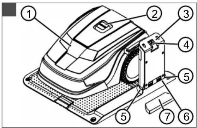
2.7 Base station
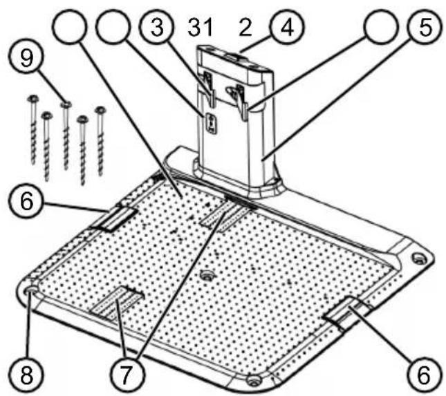
No. Component
| 1 Base plate |
| 2 LEDs for status display |
| 3 Charging contact |
| 4 Home button |
| 5 Charging station |
| 6 Cable shaft |
| 7 Wheel recess |
| 8 Hole for screw nails (9) |
| 9 Screw nails |
* Robolinho 700/1200/2000
2.8 Rechargeable battery
The rechargeable battery can be changed by the user.
NOTE Fully charge the rechargeable battery before using it for the first time. The rechargeable battery can be charged in any charge status. Interrupting charging does not damage the rechargeable battery. The rechargeable battery can only be charged after the appliance has been switched on.
The rechargeable battery is partially charged on delivery. The rechargeable battery is regularly recharged during normal operation. The appliance returns to its base station for this.
■ The integrated electronic control unit with a monitoring function terminates the charging
procedure when a 100% charge status is reached.
The charging process only functions with perfect contact of the charging contacts on the base station with the contact surfaces of the appliance.
The built-in protection circuit prevents the rechargeable battery from being charged at temperatures above 45 °C. This prevents irreparable damage to the rechargeable battery.
If the operating time of the battery is reduced in spite of it being fully charged, have the battery replaced by a new genuine battery. This task should be carried out by an AL-KO dealer, technician or service partner.
If the battery charge level has dropped below the threshold set by the manufacturer as a result of ageing or excessively long storage, this means it can no longer be recharged. Have the battery and the monitoring electronic control unit checked by an AL-KO dealer, technician or service partner, and replace them if necessary.
The rechargeable battery status is shown on the display. Check the rechargeable battery status after about 3 months in storage. To do so, switch on the appliance and read off the rechargeable battery status. If the rechargeable battery is now only charged to approx. 30 % or less, place the appliance in the base station and switch it on so the rechargeable battery is charged. If the charging station was removed to store the base station (see chapter 11.2 "Storing the charging pole", page 56), first mount it again in reverse order and connect the base station to the mains supply again.
If electrolyte has escaped into the appliance: Have the appliance repaired by an AL-KO service centre.
If the rechargeable battery has been removed from the appliance: If the eyes or hands have come into contact with escaped electrolyte, flush them immediately with water. Immediately consult a doctor.
2.9 Functional description
Moving on the grass surface
The appliance moves freely in a mowing area delimited by a boundary cable. The appliance is oriented by sensors that detect the magnetic field of the boundary cable.
If the appliance encounters an obstacle, it stops and then continues in another direction. If the appliance gets into a situation where it cannot operate, this is indicated by a message on the display.
Robolinho 700/1200/200: If the appliance detects moisture when the rain sensor is switched on, it automatically returns to the base station.
Mowing and charging
The mowing phases alternate constantly with the charging phases. If the charge of the rechargeable battery drops to a specific value (display: 0 %) during mowing, the appliance returns to the base station along the boundary cable.
Mowing programs are preset and can be customised on the appliance or in the app.
Each time the mowing motor is started, its direction of rotation is changed which doubles the service life of the cutting blades.
2.10 WLAN radio module and AL-KO inTOUCH app
The robot lawn mower is equipped with a WiFi radio module. This allows convenient control, setting and monitoring via app from a mobile device (smartphone, tablet, etc.).
i NOTE The mobile device being used requires an Internet connection in order to use the inTOUCH app.
NOTE In order to ensure that the latest software version is always installed on the robot lawn mower, it must be connected to the Internet via a WiFi network. The AL-KO inTOUCH app provides notification when there are new software updates for the robot lawnmower. They are downloaded automatically.
AL-KO inTOUCH app
The AL-KO inTOUCH app can be downloaded for Android-based devices from the Google Play Store and for iOS-based devices from the Apple App Store:


After installing the app, the user must first log in. The Quick Installation Guide is automatically called up the first time the app is started. Follow the instructions to install the robot lawn mower in the garden, and then to connect it to the AL-KO inTOUCH app.
NOTE The robot lawnmower connects to a 2.4 GHz WLAN only.
5 GHz WLAN networks are not supported.
To connect to the AL-KO inTOUCH app, the robot lawnmower and smartphone must be within range of a router with sufficient signal strength (recommendation: min. 50%).
- Start the AL-KO in TOUCH app.
- Create a user account with "REGISTER". Enter the user name and password.
- Log in with the previously created user account.
- Start the connection wizard via "APPLIANCES" and "NEW APPLIANCE".
- Follow the further instructions.
NOTE If the robot lawnmower moves into an area of the garden with a poor or no WLAN connection, the settings of the AL-KO inTOUCH app will only be carried out when the robot lawnmower returns to an area with a good signal. If the local WLAN strength of the router does not cover the entire garden, its range can be extended with a standard repeater.
In the event of malfunctions, a dealer with the AL-KO inTOUCH app installed can help you. The robot lawnmower must be enabled for the dealer via the AL-KO inTOUCH app.
Besides remote access to connected robot lawn mowers, the AL-KO inTOUCH app offers other functions such as product registration, gardening tips, gardening manual or push notifications in the event of a fault.
3 SAFETY
3.1 Intended use
This appliance is intended solely for use in non-commercial applications. Any other use (as well as unauthorised conversions or add-ons) are regarded as con-
trary to the intended use and will result in exclusion of the warranty as well as loss of conformity (CE mark); the manufacturer will thus decline any responsibility for damage and/or injury suffered by the user or third parties. The application limits of the appliance are:
Max. area:
■ Robolinho 500: 500 m²
■ Robolinho 700: 700 m²
■ Robolinho 1150: 1200 m²
■ Robolinho 1200: 1200 m²
■ Robolinho 2000: 2000 m²
■ Max. upward/downward slope: 45 % (24°)
■ Max. lateral inclined angle: 45 % (24°)
■ Temperature:
- Charging: 0 – 45 °C
■ Mowing: 0 – 55 °C
3.2 Possible misuse
This machine is not suitable for use in public gardens, parks, sports stadiums, and in agriculture and forestry.
3.3 Safety and protective devices
WARNING! Risk of injury.
Defective and disabled safety and protective devices can result in serious injury.
■ Have any defective safety and protective devices repaired.
■ Never disable safety and protective devices.
The appliance can only be started by entering a PIN (Personal Identification Number). This prevents the appliance from being switched on by unauthorised persons. The factory setting of the PIN is 0000. The PIN can be changed, see chapter 5.2 "Making the basic settings", page 50.
If the PIN is entered incorrectly 3 times, the PUK (Personal Unlocking Key) must be entered. If this is also entered incorrectly, the user must wait 24 hours until entering it again.
- Keep the PIN and PUK so that they are inaccessible to unauthorised persons.
3.3.2 Sensors
The appliance is provided with several safety sensors. It does not restart automatically after be-
ing switched off by a safety sensor. The error message is shown on the display and must be acknowledged. The reason for the triggering of the sensor must be resolved.
Lifting sensor
If the appliance is raised by the housing during operation, the travel drive switches off and the cutting blades are stopped.
Bump sensors for obstacle detection
The appliance is equipped with sensors that ensure it changes its direction of travel if it encounters obstacles. When it encounters an obstacle, the top part of the deck is shifted slightly and the shock sensor triggered.
Tilt sensor in direction of travel/sideways
If an upward or downward slope or a laterally inclined angle of 24^ (45 %) is reached in the direction of travel, the appliance is turned or the appliance changes its direction of travel.
Rain sensor (Robolinho 700/1200/2000)
The appliance is equipped with a rain sensor that (when activated) interrupts the mowing procedure in case of rain, and ensures that the appliance returns to the base station.
NOTE The appliance can be operated reliably in the immediate vicinity of other automatic lawn mowers. The signal used in the boundary cable corresponds to the standard defined by the European Garden Machinery Industry Federation (EGMF) with regard to electromagnetic emissions.

3.4 Safety instructions
3.4.1 Operator
■ Young people under 16 years of age, persons with limited physical, sensory or mental abilities or with a lack of experience and knowledge and persons who do not know the operating instructions must not use the device. Heed any country-specific safety regulations concerning the minimum age of the user.
- Do not operate the appliance if you are under the influence of alcohol, drugs or medication.
3.4.2 Personal protective equipment
■ Wear clothing and protective equipment in accordance with the regulations in order to avoid injury.
■ The personal protective equipment comprises:
■ Long trousers and sturdy shoes.
■ During maintenance and care: Protective gloves.
3.4.3 Safety of persons and animals
In areas accessible to the public, affix warning information with the following content around the mowing area:
IMPORTANT! Automatic lawn mower in operation! Do not approach the appliance! Supervise children.
■ Make sure that children and other persons are not present in the vicinity of the appliance when it is operating or climb onto the appliance and do not play with the appliance.
■ Sitting on the appliance and reaching into the cutting blade is forbidden.
- Keep body and clothes away from the cutting unit.
3.4.4 Appliance safety
■ Before working, make sure that there are no objects (e.g. branches, glass or metal pieces, and items of clothing, stones, garden furniture, garden utensils or toys) in the work area of the appliance. They can damage the cutting blade of the appliance or can be damaged by the appliance.
■ Only use the appliance under the following conditions:
■ The appliance is not soiled.
■ The appliance shows no damage or wear.
■ All controls function properly.
- The base station and power supply as well as their electrical supply cables are undamaged and function properly.
■ Always replace defective parts with original spare parts from the manufacturer.
■ Have the appliance repaired if it has been damaged.
■ The user of the appliance is responsible for accidents of the appliance involving other persons or their property.
3.4.5 Electrical safety
■ Never operate the appliance when a lawn sprinkler is oper-
ating on the mowing area at the same time.
■ Do not spray the appliance with water.
■ Do not open the appliance.
4 ASSEMBLY
4.1 Unpacking the machine
- Open the packaging carefully.
- Carefully remove all components from the packaging and check for transport damage.
Note: Notify your AL-KO dealer or service partner immediately if any transport damage is discovered.
- Check the scope of supply, see chapter 2.1 "Scope of supply", page 38.
If the appliance is going to be sent on, retain the original packaging and accompanying documents. They will also be required for return shipment.
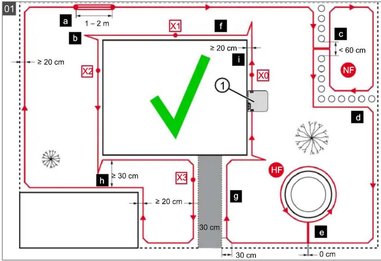
4.2 Planning the mowing areas (01)
Location of the base station (01/1)
■ Shortest possible distance to the largest mowing area
Level surface
■ Protected against direct sunlight and harsh weather conditions
■ Connection option for power source
■ Free accessibility to the robot lawn mower
Routing the boundary cable (01)
The boundary cable must be laid in a continuous loop in a clockwise direction.
Corridors between mowing areas (01/h)
A corridor is a narrow section in the grass surface and can be used to connect two mowing areas.
Main area and secondary area(s) (01)
■ Main area (01/HF): This is the grass surface on which the base station is located and whose entire surface can be mowed automatically by the appliance.
Secondary area (01/NF): If a grass surface cannot be reached by the appliance from the main area, carry the appliance to the secondary area by hand if necessary. Secondary areas can be processed using manual operation.
The main area and secondary areas are bounded by the same continuous boundary cable, however.
Location of start points (01/X0 - 01/X3)
At the specified mowing time, the appliance moves along the boundary cable to the specified start point and begins to mow there.
The start points can be used to specify which areas of the mowing area are to be mowed several times.
4.3 Preparing the mowing areas
- Check that the grass surface is larger than the area covered by the appliance. If the grass surface is too large, an irregularly mown lawn will result. Reduce the size of the grass surface to be mowed if necessary.
- Before installation of the base station and boundary cable or start-up of the appliance: Use a lawn mower to mow the grass surface to a low cutting height.
-
Remove any obstacles on the grass surface or exclude them with the boundary cable (see chapter 4.5.3 "Excluding obstacles", page 48):
-
Flat obstacles that will be run over and could damage the cutting blade (e.g. flat stones, transitions from the grass surface to the terrace or paths, plates, kerbstones, etc.)
■ Holes and protrusions in the grass surface (e.g. molehills, burrowing holes, pine cones, fallen fruit, etc.)
■ Steep ascents and descents of more than 45 % (24°)
■ Bodies of water (e.g. ponds, streams, swimming pools, etc.) and their demarcation to the grass surface
■ Shrubs and hedges that can become broader
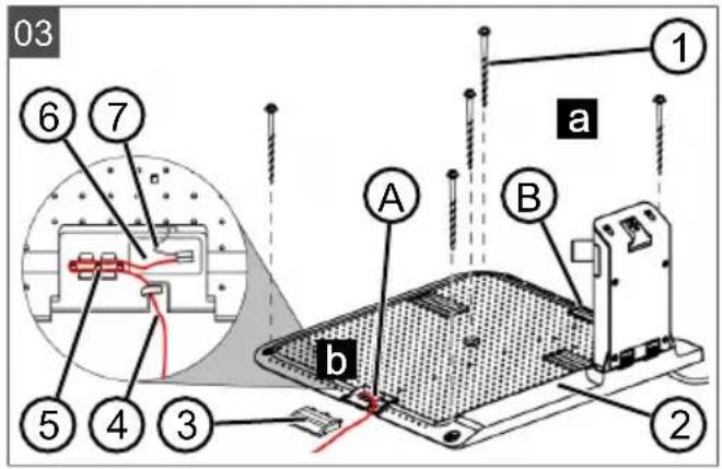
4.4 Setting up the base station (03/a)
- Place the base station (01/1) at right angles to the planned location of the boundary cable as described below:
■ Level (check with spirit level)
■ Straight and level entrance and exit
■ Not arched (the charging station must not bend or tilt during subsequent tightening of the screw nails)
- Fix the base station (03/2) to the floor with four screw nails (03/1).
4.5 Installing the boundary cable
NOTE Robolinho 500/1150: If the supplied boundary cable is too short, an extension cable can be obtained from your AL-KO dealer or service partner.
4.5.1 Connecting the boundary cable to the base station (03/b)
- Pull the boundary cable (03/4) out of the packaging.
- Remove the cover of the cable shaft (03/3) on the connection (03/A).
- Insulate the end of the boundary cable (03/6) and insert into the terminal (03/7).
- Close the terminal.
- Lead the boundary cable through the strain relief (03/5) out of the cable shaft with cable reserve.
i NOTE The cable reserve allows smaller corrections to be carried out on the cable guide later.
- Place the cover on the cable shaft.
4.5.2 Routing the boundary cable (01)
The boundary cable can be laid on the lawn and as much as 10 cm under the turf. The laying under the turf can be carried out by the dealer.
Both variants can be combined with one another.
IMPORTANT! Danger of damaging the
boundary cable. If the boundary cable is damaged or cut, the transmission of the control signals to the appliance is no longer possible. In this case, the boundary cable must be repaired or replaced. The boundary cables are available from AL-KO.
■ Always route the boundary cable directly on the ground. If necessary, secure with an additional lawn peg.
- When laying the boundary cable and during operation, protect the boundary cable from damage.
- Do not dig or scarify in the vicinity of the boundary cable.
- Attach the boundary cable at regular intervals with lawn pegs or route it underground (at a max. depth of 10 cm).
-
Route the boundary cable around obstacles: see chapter 4.5.3 "Excluding obstacles", page 48.
-
Create corridors between individual mowing areas: see chapter 4.5.4 "Enclosing corridors (01/h)", page 49.
- Exclude excessive upward or downward slopes: see chapter 4.5.5 "Excluding downward slopes (11)", page 49.
- Create loops of cable: see chapter 4.5.6 "Creating loops of cable (07)", page 49.
- After completing the routing of the boundary cable, connect to the connector (03/B) of the base station: see chapter 4.5.1 "Connecting the boundary cable to the base station (03/b)", page 48.
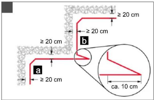
4.5.3 Excluding obstacles
Depending on the surroundings of the working area, the boundary cable must be routed at different distances to obstacles. Use the ruler that can be removed from the packaging to determine the correct distance.
NOTE Exclusions are only necessary if they cannot be detected by the bump sensors of the appliance. Avoid too many or unnecessary exclusions. Recesses that are smaller than 6 cm must be excluded, otherwise the appliance may cause damage.
Distance from walls, fences, beds: min. 20 cm (01)
The appliance moves along the boundary cable with an offset of 20 cm to the outside. Therefore, route the boundary cable at a distance of at least 20 cm from walls, fences, beds, etc.
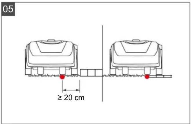
Distance from terrace edges and paved paths (05)
If the terrace or path edge is higher than the grass surface, a distance of at least 20 cm must be complied with. If the edge of the terrace or path is at the same height as the grass surface, the cable can be routed exactly along the edge.
Distance of obstacles from the boundary cable (01)
If the boundary cables are precisely folded up away from the obstacle or towards the obstacle, i.e. distance 0 cm, the appliance moves beyond the boundary cable. Do not cross the boundary cables (02/c), but lay them parallel (01/e).
Routing the boundary cable around corners (06)
For inwards going corners (06/a): Route the boundary cable diagonally to avoid the appliance becoming caught in the corner.
For outside corners with obstacles (06/b): Route the boundary cable in a point in order to avoid a collision of the appliance with the corner.
For outside corners without obstacles: Route the boundary cable at an angle of 90^ .
4.5.4 Enclosing corridors (01/h)
In the corridor the following distances must be complied with:
■ Total width: min. 60 cm
■ Distance of the boundary cable to the edge: 20 cm
■ Distance between the boundary cables: min. 20 cm
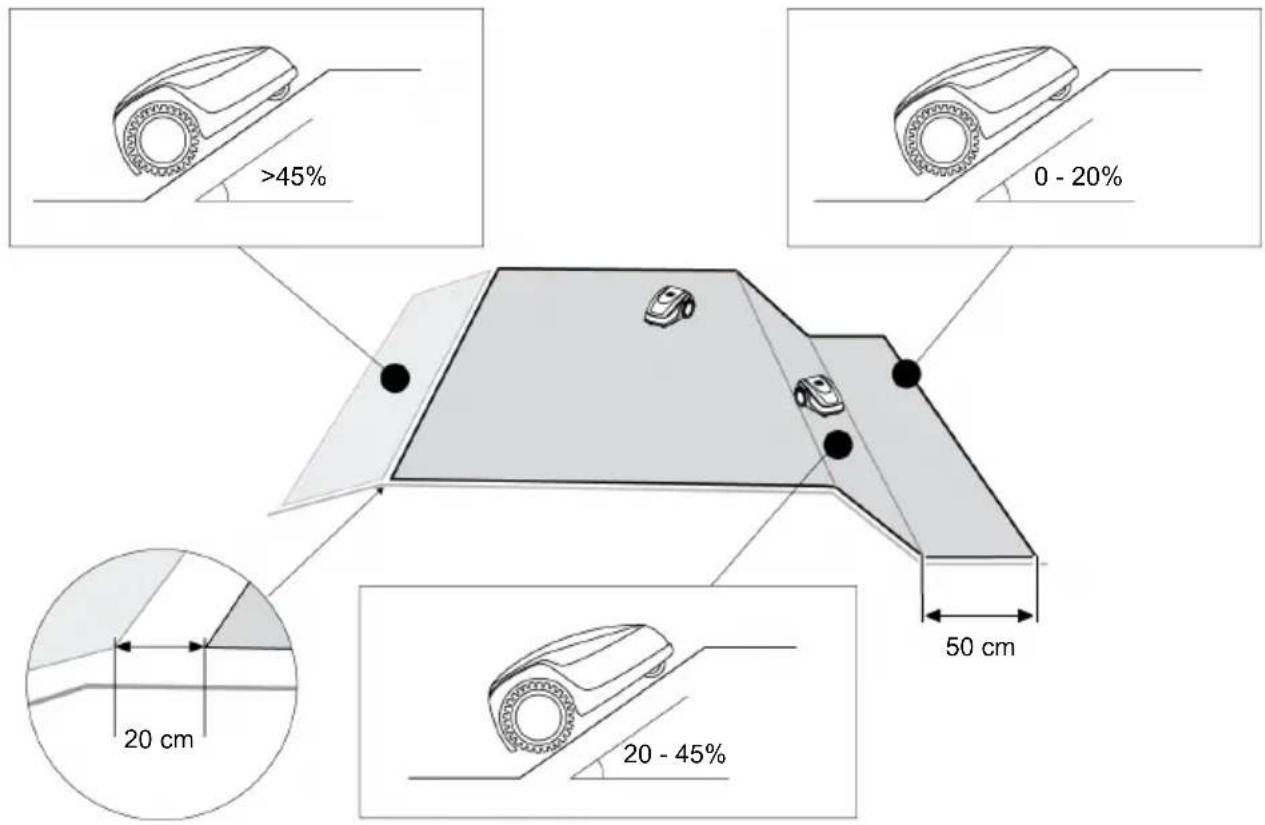
4.5.5 Excluding downward slopes (11)
Downward slopes that are greater than 45 % must be excluded with the boundary cable (45 % = 45 cm downward slopes per 1 m horizontally).
The boundary cable must not be laid over a gradient of more than 20%. In order to avoid problems when turning, maintain a distance of 50 cm to the 20% gradient. If the gradient at the outer edge of the working area is more than 20% at any point, lay the boundary cable on the flat ground at a distance of 20 cm from the start of the gradient.
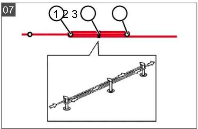
4.5.6 Creating loops of cable (07)
Spare loops of cable should be incorporated at regular intervals in order to reposition the base station or to extend the mowing area even after the mowing area has been laid out.
Select the number of spare cable loops according to your own judgement.
i NOTE In the case of spare cable loops, do not form open loops.
- Lead the boundary cable around the current lawn peg (07/1) and then back to the previous lawn peg (07/3).
- Then lead the boundary cable to the current lawn peg again. This creates a loop. The cables must be close together.
- If necessary, attach the loop to the ground in the middle with an additional lawn peg (07/2).
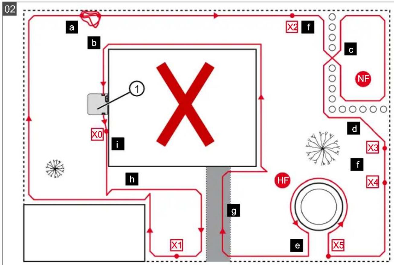
4.5.7 Typical faults in cable routing (02)
- Spare cable loops of the boundary cable are not laid in an even, elongated loop (02/a).
■ The boundary cable is not routed properly around corners (02/b).
■ The boundary cable is crossed over or not routed clockwise (02/c).
The boundary cable is routed too imprecisely so that edge areas of the grass surface cannot be mowed (02/d).
The boundary cable is not routed lying directly next to itself when guided towards and back from the edge to an obstacle inside the lawn (02/e).
■ The start points are set too far away from the base station (02/f).
The boundary cable is routed beyond the edge of the grass surface (02/g).
- When routing the boundary cable, the minimum distance for corridors of 20 cm is undercut (02/h).
The boundary cable is routed too close (i.e. at a distance of less than 20 cm) to obstacles that cannot be driven over (02/i).
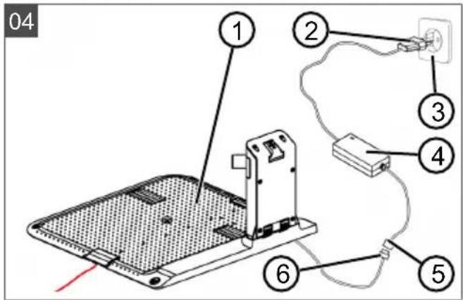
4.6 Connecting the base station to the power source (04)
- Place the power supply (04/4) in a dry location that is protected against direct sunlight and sufficiently close to the base station (04/1).
- Connect the low voltage cable of the power supply (04/5) and the cable of the base station (04/6) with each other.
- Plug the power plug of the power supply (04/2) into a power socket (04/3).
NOTE We recommend connecting the power supply to the mains supply via an earth leakage circuit breaker (ELCB) with a rated leakage current < 30 mA.
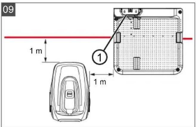
4.7 Checking the connections on the base station (04)
- Check that both LEDs on the front side of the charging station (09/1) light. If not:
■ Disconnect the mains plug.
- Check that all plug connectors of the power source and the boundary cable are positioned correctly and check for damage.
Status indications of the LEDs
| LEDs Operating states |
| Green | ■ Lights up when the boundary cable is laid correctly and the loop is intact. |
LEDs Operating states
Yellow
■ Lights up if the power source is intact.
5 START-UP
This chapter describes the activities and settings that are necessary to put the appliance into operation for the first time. For all further settings, refer to see chapter 7 "Settings", page 51.
5.1 Charging the rechargeable battery (08)
During normal operation, the battery of the appliance is regularly charged automatically.
NOTE Fully charge the rechargeable battery before using it for the first time. The rechargeable battery can be charged in any charge status. Interrupting charging does not damage the rechargeable battery. The rechargeable battery can only be charged after the appliance has been switched on.
- Place the appliance (08/1) in the base station (08/3) so the contact surfaces of the appliance touch the charging contacts of the base station.
- Switch on the appliance with .
- The display on the appliance shows Battery is being recharged. If not: see chapter 13 "Help in case of malfunction", page 58.
5.2 Making the basic settings
- Open the cover flap.
- Switch on the appliance with .€mware, code and type are displayed.
- In the menu for language selection, select the language with ▲ and accept with —.
-
In the Login > Enter PIN menu, enter the preset PIN 0000. To do so, select the digit 0 with ▲ in sequence and always accept with . After entering the PIN, access is enabled.
-
In the Change PIN menu:
■ Under Enter new PIN, enter a self-selected new four-digit PIN. To do so, select one digit in sequence with ▲ and respectively confirm with —
■ Under Reenter new PIN, enter the new PIN again. If both entries are identical, PIN changed is displayed.
-
In the Enter date menu, set the current date (format: DD.MM.20YY). To do so, select one digit in sequence with ▲ and re-spectively confirm with —
-
In the Enter time > HH:MM menu, set the current time (format: HH:MM). To do so, select one digit in sequence with ▲ and respectively confirm with —
The basic settings have been completed. The Not calibrated Press Start key status is displayed.
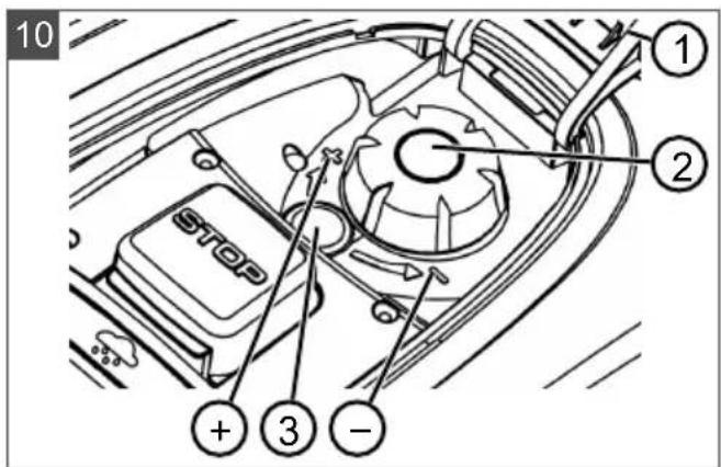
5.3 Setting the cutting height
The cutting height can be manually adjusted continuously between 25 - 55 mm.
NOTE A cutting height of 55 mm is recommended for the calibration movement (see chapter 5.4 "Carrying out an automatic calibration movement", page 50) and for teaching-in the starting points (see chapter 7.5.2 "Setting the start points", page 52).
- Open the cover (10/1).
-
Set the cutting height (the current cutting height is displayed in the window (10/3) in millimetres):
■ Increase the cutting height (i.e. lawn height): Turn the rotary knob (10/2) clockwise (10/+).
■ Decrease the cutting height (i.e. lawn height): Turn the rotary knob (10/2) anticlockwise (10/−).
-
Close the cover.
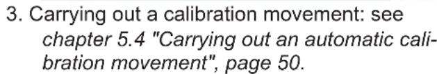
5.4 Carrying out an automatic calibration movement
NOTE Before commissioning, carry out the calibration movement (see chapter 5.4 "Carrying out an automatic calibration movement", page 50) or teaching-in of the starting points (see chapter 7.5.2 "Setting the start points", page 52).
Place the appliance at the starting position (09)
- Place the appliance at the starting position inside the mowing area:
At least 1 m left and 1 m in front of the base station
■ Aligned with the front side to the boundary cable
Starting the calibration movement
-
Check that there are no obstacles in the expected movement area of the appliance. The appliance must be able to move over the boundary cable with both front wheels. If necessary, remove obstacles or lay the cable temporarily inwards (min. 35 cm required).
-
Start the appliance with .the following is shown on the display:
■ ! Caution ! Starting Motors
■ Calibration, Phase [1]
During the calibration movement
To determine the signal strength inside the boundary cable, the appliance first moves twice straight beyond the boundary cable and then into the base station and comes to a stop there.
■ The Calibration completed message is shown on the display.
■ The rechargeable battery is being charged.
NOTE The appliance must come to a stop when it moves into the base station. If the appliance does not touch the contacts when it moves into the base station, it moves further along the boundary cable. If the appliance moves through the base station, the calibration procedure has failed. In this case, the base station must be better aligned and the calibration procedure repeated.
After the calibration movement
The preset current mowing duration is displayed. For all further settings, refer to see chapter 7 "Settings", page 51.
Robolinho 700/1200/2000
NOTE To ensure proper operation and reduce error messages, the loop length must be measured.
See also
Setting the start points [▶ 52]
6 OPERATION
6.1 Starting the appliance manually
-
Switch on the appliance with . For unscheduled edge mowing: see chapter 7.7 "Edge mowing with a manual start", page 54.
-
Start the appliance manually with .
6.2 Cancelling mowing
■ Robolinho 500/1150: Press 📂 on the appliance.
■ Robolinho 700/1200/2000: Press on the base station (08/4) or on the appliance.
The appliance moves automatically into the base station. It deletes the mowing plan of the current day and starts again the next day for the set time.
- Press 🏠 in the appliance.
The mowing is interrupted for half an hour.
■ Press 📊 on the appliance.
The appliance is switched off.
NOTE In dangerous situations, the appliance can be stopped with the STOP button (08/2).
6.3 Mowing the secondary area (01/NF)
-
Lift the appliance and place in the secondary area by hand.
-
Switch on the appliance with .
-
Call up the main menu with .☐
-
o▲* settings
-
o▲* sub zone mowing
-
Select the mowing time with ▲.
- Start the appliance manually with .
Depending on the setting: The appliance mows for the set time period and then switches off or mows until the rechargeable battery is flat.
After mowing the secondary area, place the appliance in the base station again by hand.
7 SETTINGS
7.1 Calling up the setting – General
-
Call up the main menu with .☐
Note: The asterisk * in front of the menu item indicates that it has just been selected.
-
or* Settings
-
Select the required menu item with and accept with ▲ ▼
-
Make the settings.
Note: The menu items are described in the following sections.
-
Return to the main menu with .☐
NOTE Further menu items: see chapter
5.2 "Making the basic settings", page 50.
-
on* key clicks
-
Activating/deactivating the button tones:
or Activate : —
Activate the button tones.
or deactivate : —
Deactivate the button tones.
7.3 Activating/deactivating Eco mode (Robolinho 700/1200/2000)
In Eco mode, the appliance switches to energy-saving mode. This reduces the energy consumption and noise emissions.
NOTE With high and thick grass and for thick rolled turf, this is not recommended or may not be possible.
-
or * EcoMode
-
Activating/deactivating Eco mode:
■ Activate —
Activate Eco mode.
■ Deactivate —
Deactivate Eco mode.
7.4 Setting the rain sensor (Robolinho 700/1200/2000)
NOTE Mowing when the grass is dry reduces soiling. By activating the rain sensor and setting a delay time, it is possible to prevent the appliance mowing when the grass is wet.
If the rain sensor is activated, the appliance moves back into the base station when the rain begins. It remains there until the rain sensor has dried. Then it waits for the time period that is set as the delay before it continues mowing. The sensitivity of the rain sensor is adjustable.
-
or * Rain sensor
-
Activating/deactivating the rain sensor:
or Activate : —
Activate the rain sensor.
or deactivate : —
Deactivate the rain sensor.
- Setting the delay of the rain sensor:
or After rain delay
- xx hours xx minutes
Select the required value for the delay with ▲ and accept with .
- Setting the sensitivity of the rain sensor:
or Rain sensitive
■ Select the required value for the sensitivity with ▲ and ▼ accept with .
7.5 Setting the mowing program
7.5.1 Setting the mowing program – General
-
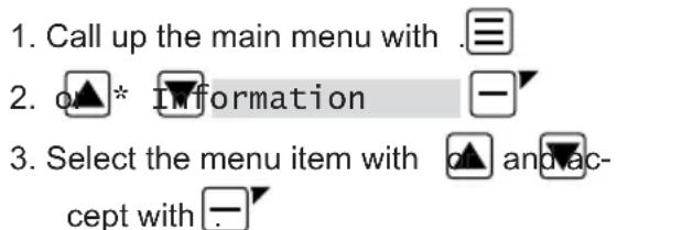
Call up the main menu with .☐
-
o▲* Programs -
-
Select the menu item with ▲ and ▼ accept with —
-
Carry out the settings.
Note: The menu items are described in the following sections.
7.5.2 Setting the start points
Teaching-in start points
-
Place the appliance in the base station.
-
Switch on the appliance with .
-
Call up the main menu with .☐
-
o* Programs
-
or* Entry Point
-
o* Interactive teach
-
or* Start interactive entry point teaching
or start. The appliance moves along the boundary cable.
or set when the appliance has reached the required start point. The start point is stored.
- or ▲Set▼entry point 1 if no — start point has been specified during the teaching-in movement. If no start point has been specified here, the start points are automatically specified.
- or▲Entry point x: XXm if the last start point has been reached.
Manually specifying start points (01)
The first start point (01/X0) is pre-set and is 1 m to right of the base station. Other start points can be defined after this point:
■ Robolinho 500/700/1150: Up to three start points (X1 – X3)
■ Robolinho 1200: up to six start points (X1 – X6)
■ Robolinho 2000: up to nine start points (X1 – X9)
When specifying the start points, heed the following:
Entry Point
-
- or*
Point X1 at [020m]
-
Select one digit in sequence with and always accept with


- o
Point x2 at [075m]
-
Select one digit in sequence with and always accept with □-


- If necessary, specify further start points.
- Return to the main menu with .☐
7.5.3 Setting the mowing times
NOTE There must be at least 30 min. between programming the mowing times and the mowing start. If not, the appliance starts 30 min after the last press of the button at the earliest.
In the weekly Program menu item, the days of the week and time periods when the appliance should mow are set. Adapt these settings to the size of your garden if necessary. If unmown areas are still visible after approx. one week, increase the mowing periods.
- or *
weekly Program

or All Days [X]: The appliance mows every day at the set times. If All Days [ ] is shown, the appliance only mows on the set days of the week.
or Monday [X]...* Sunday [X]: The appliance mows for the set time periods on the set day of the week. If Monday [ ] is shown, for example, the appliance does not mow on the respective day.
or ▲ change : Activate the respective day [X] or deactivate it [ ], and set the time periods, type of mowing and the start points.
- Make the settings for every day or the respective day:
e.g. *[M] 07:00-10:00 [?]: Normal mowing [M] from 07:00 - 10:00 am with automatically changing start point 0 - 9 [?].
e.g. *[R] 16:00-18:00 [1]: The appliance starts with edge mowing [R] at 4 pm and moves along the entire boundary cable. The area mowing then begins at start point 1 [1]. At 6 pm or as soon as the rechargeable battery is discharged, the appliance moves back to the base station.
or Change : Change the selected setting.
or Continue : Confirm the changes setting and continue to the next setting.
- or ▲ Save ▼: Save all changed settings of the menu item.
7.6 inTOUCH
An existing connection to a gateway can be disconnected. This means the appliance is ready to establish a new connection for 30 minutes.
NOTE To establish a connection later, the connection must first be disconnected again, even if the appliance was not previously connected with a gateway.
- or *in TOUCH -
- Reset connection
Appliance reports: Done.
- Confirm with and return to the menu.
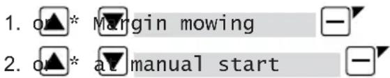
7.7 Edge mowing with a manual start
For a manual start, the setting can be made here that the appliance begins with edge mowing.
Carrying out the edge mowing at the programmed mowing time periods: see chapter 7.5.3 "Setting the mowing times", page 53.
7.8 Setting the secondary area mowing

- Setting the mowing time periods:
or inactive : —
Secondary area mowing is switched off.
or active : The appliance mows until the rechargeable battery is flat.
or mowing time in min : The appliance mows the secondary area for the set time period. The following mowing time periods can be set: 30/60/90/120/until rechargeable battery flat.
7.9 Setting the display contrast
If the display is difficult to read, e.g. in sunlight, the display can be improved by changing the display contrast.
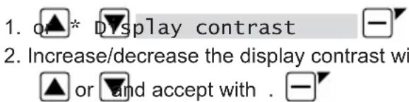
- Increase/decrease the display contrast with
7.10 Setting lock
If the setting lock is deactivated, the PIN must only be entered when acknowledging safety-relevant faults.

- Activating/deactivating the setting lock:
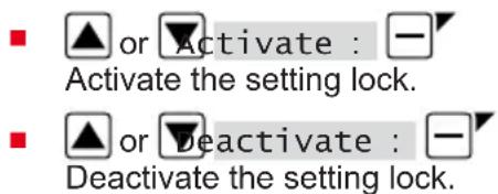
Activate the setting lock.
Deactivate the setting lock.
7.11 Recalibrating
If the position or length of the boundary cable has been changed or the appliance no longer finds the boundary cable, recalibration is necessary.


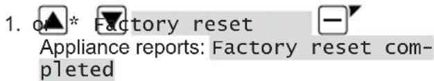
7.12 Restoring factory settings
The factory settings of the appliance can be restored, e.g. before selling the appliance.
The Information menu is used for displaying machine data. No settings can be made in this menu.
Note: The menu items are described in the following sections.

Blades service
Shows in how many operating hours a blade service is required. The counter can be reset manually. Have the blade service carried out by an AL-KO dealer, technician or service partner.
Reset the counter for blade service:

Hardware
Shows information on the appliance, such as type, year of manufacture, operating hours, serial number, number of mowing operations, total mowing time, number of charging cycles, total charging time, length of the loop of the boundary cable.
Software
Shows the software version.
NOTE Keep the software of the Robolinho automatic lawn mower up to date at all times. Check the firmware version at regular intervals and update it as necessary. The Robolinho updater software can be found on the Internet at: www.al-ko.com/shop/de/robolinho-autoupdater
Program Info
Shows current settings such as the total weekly mowing time.
Failures
Shows the fault messages that last occurred with date, time and fault code.
9 MAINTENANCE AND CARE
CAUTION! Risk of injury. Sharp-edged and moving appliance parts can lead to injury.
■ Always wear protective gloves during maintenance, care and cleaning work.
9.1 Cleaning
IMPORTANT! Danger from water. Water in the automatic lawn mower and in the base station leads to damage on electrical components.
- Do not spray the automatic lawn mower and base station with water.
Clean the automatic lawn mower
CAUTION! Danger of injury due to the cutting blade. The cutting blades are very sharp and can cause cutting injuries.
■ Wear protective gloves.
■ Make sure that parts of the body do not get into the cutting blade.
Once a week, carry out the following:
- Switch off the appliance with .
- Wipe off the surface of the housing with a broom, a brush, a damp cloth or a fine sponge.
- Brush off the underside, mower deck and cutting blade with a brush.
- Check the cutting blade for damage. If necessary, replace the following: see chapter 9.3 "Replacing the cutting blades", page 55.
Cleaning the base station
- Regularly remove grass residues and leaves or other objects out of the base station.
- Wipe off the surface of the base station with a damp cloth or a fine sponge.
9.2 Regular checks
General checks
- Once a week, check the whole Installation for damage:
Machine
Base station
■ Boundary cable
Power supply
- Replace defective parts by original spare parts from AL-KO or have them replaced by an AL-KO service centre.
Check the rollers can move freely
Once a week, carry out the following:
- Carefully remove grass residues and soiling from the areas around the rollers. Use a broom and cloth for this.
- Check that the rollers run freely and that they can be steered.
Note: If the rollers do not move freely or cannot be steered, have them replaced by an AL-KO service centre.
- Use a cloth to remove soiling and then lightly grease with contact grease.
- Disconnect the mains plug.
- Press the charging contacts in the direction of the base station and release them. The charging contacts must spring back into the initial position.
Note: If the charging contacts do not spring back, have them replaced by the AL-KO service centre.
9.3 Replacing the cutting blades
CAUTION! Danger of injury due to the cutting blade. The cutting blades are very sharp and can cause cutting injuries.
■ Wear protective gloves.
■ Make sure that parts of the body do not get into the cutting blade.
IMPORTANT! Damage to the appliance due to incorrect repair. The blade plate can be damaged by the alignment of a bent, built-in cutting blade.
■ Do not align bent cutting blades.
- Replace bent cutting blades by original spare parts from AL-KO.
Worn or bent cutting blades must be replaced.
-
Switch off the appliance with
-
Put down the appliance with the cutting blades pointing upwards.
- Unscrew the fastening screws.
- Take the cutting blade out of the blade seat.
- Clean the blade seat with a soft brush.
NOTE The cutting blades are sharpened along the entire length and can therefore also be mounted rotated by 180^ , which doubles their runtime.
- Replacing the cutting blades:
If cutting blades have not been rotated since the initial mounting: Rotate the cutting blades by 180° and insert into the blade seat again with the sharpened side pointing towards the appliance, and tighten the fastening screws again by hand.
If the cutting blades have already been rotated once since the initial mounting: Insert new cutting blades into the blade seat again with the sharpened side pointing towards the appliance, and tighten the new fastening screws by hand.
Note: It is only allowed to use original spare parts from AL-KO.
In case of stubborn dirt that cannot be removed with a brush, the blade plate must be replaced because an imbalance can lead to increased noise levels, greater wear and malfunctions.
As a rule, the clearer blades do not need to be replaced.
10 TRANSPORT
To transport the appliance, proceed as follows:
- Stop the appliance with ton.
d the stop but-
- Switch off the appliance with

- Lift the appliance with both hands on the housing:
■ Do not touch the cutting blades.
■ The cutting blades must always point away from the body.
11 STORAGE
11.1 Storing the automatic lawn mower
The appliance must be stored over winter or when it is to be taken out of service for an expected duration of longer than 30 days.
- Fully charge the rechargeable battery (see chapter 5.1 "Charging the rechargeable battery (08)", page 50)
- Thoroughly clean the appliance (see chapter 9.1 "Cleaning", page 55).
- Store the appliance:
■ upright on all wheels
■ at a dry, lockable location protected from frost
■ out of the reach of children
11.2 Storing the charging pole
The charging pole must be stored over winter or when it is expected to be out of service for an expected duration of longer than 30 days.
- Disconnect the power supply from the mains supply and unplug from the base station.
- Removing the charging pole:
■ Unscrew both screws of the charging station (08/5).
■ Remove the charging station from the base station by tilting.
■ Undo the plug connection of the cables from the base station and charging station.
■ Close the opening of the base (08/6) with the included winter cover (08/7).
- Storing the charging pole:
■ at a dry, lockable location protected from frost
■ out of the reach of children
11.3 Winter storage of the boundary cable
The boundary cable can remain in the ground and does not need to be removed.
12 DISPOSAL

Electrical and electronic appliances do not belong in household waste, but should be collected and disposed of separately.
■ Used batteries or rechargeable batteries that are not installed permanently in the old appliance must be removed before disposal. Their disposal is regulated by the battery law.
- Owners or users of electrical and electronic appliances are obliged by law to return them after use.
The end user bears personal responsibility for deleting his personal data from the old appliance to be disposed of.
The symbol of the crossed-through rubbish bin means that electrical and electronic appliances may not be disposed of in the household rubbish. Electrical and electronic appliances can be handed in at the following places at no charge:
- Public service disposal or collection points (e.g. municipal building yards)
- Points of sale of electrical appliances (stationary and online) provided traders are obliged to take them back or offer this voluntarily.
These statements only apply to appliances that are installed and sold in the countries of the European Union and are subject to European Directive 2012/19/EU. Different provisions may apply to the disposal of electrical and electronic appliances in countries outside the European Union.
Used batteries and rechargeable batteries do not belong in household waste, but should be collected and disposed of separately.
- For safe removal of batteries or rechargeable batteries from the electrical appliance and for information on their type or chemical system, follow the further information within the operating or installation instructions.
- Owners or users of batteries and rechargeable batteries are obliged by law to return them after use. Return is limited to the handover of customary household quantities.
Used batteries can contain harmful substances or heavy metals that can cause damage to the environment and human health. Reuse of the used batteries and use of the resources contained therein contributes to the protection of these two essential commodities.
The symbol of the crossed-through rubbish bin means that batteries and rechargeable batteries may not be disposed of in household rubbish.
In addition, if the symbol Hg, Cd or Pb appears under the rubbish bin, this stands for the following:
■ Hg: Battery contains more than 0.0005 % mercury
Cd: Battery contains more than 0.002 % cadmium
■ Pb: Battery contains more than 0.004 % lead Rechargeable batteries and batteries can be handed in at the following places at no charge:
■ Public service disposal or collection points (e.g. municipal building yards)
■ Points of sale of batteries and rechargeable batteries
■ Disposal points of the common take-back system for the used batteries of appliances
■ Disposal point of the manufacturer (if not a member of the common take-back system)
These statements apply only to rechargeable batteries and batteries that are sold in the countries of the European Union and that are subject to European Directive 2006/66/EU. Different provisions can apply to the disposal of rechargeable batteries and batteries in countries outside the European Union.

The packaging materials are recyclable. Please dispose of packaging in an environmentally friendly manner.
Remove the rechargeable battery before disposing of the appliance
The integrated rechargeable battery must be removed before disposal of the device and disposed of separately in an environmentally friendly manner.
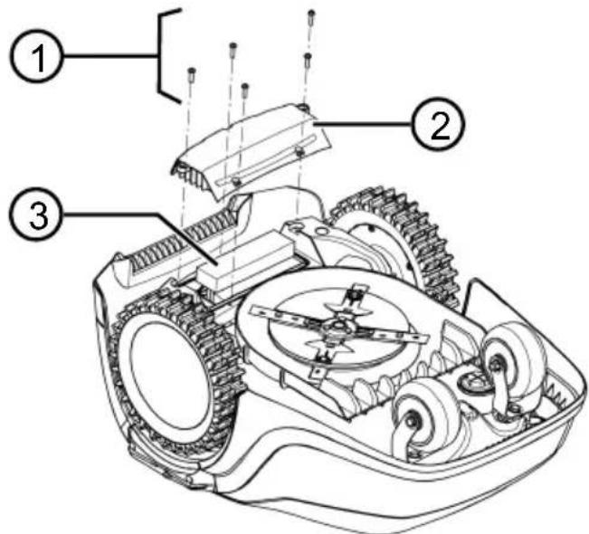
- Undo the screws (1).
- Take off the cover of the rechargeable battery compartment (2).
-
Unplug the rechargeable battery (3) and take it out.
-
Put the cover back on and fasten the screws.
13 HELP IN CASE OF MALFUNCTION
13.1 Correcting appliance and handling faults

CAUTION! Risk of injury. Sharp-edged
and moving appliance parts can lead to injury.
■ Always wear protective gloves during maintenance, care and cleaning work.
NOTE For malfunctions that are not listed in this table or that you cannot resolve yourself, please contact our customer service.
| Malfunction Cause Remedy | | |
| The appliance does not start. | Rechargeable battery is flat. Charge the appliance in the base station. |
| The appliance gets stuck and has dug itself in. The wheels continue to turn. | Bump sensors do not trigger. Contact an AL-KO service centre. |
| The grass is too high. | ■ Increase the cutting height, then lower in stages to the required height. ■ Mow the grass short with a lawn mower. |
| The appliance sits on an unevenness of the grass surface. | Eliminate the unevenness. |
| The appliance mows at the wrong time. | The appliance has the incorrect time. | Set the time. |
| The mowing duration is incorrectly set. | Set the mowing times. |
| The appliance loses the time settings. | The rechargeable battery is defective. Contact an AL-KO service centre. |
| Motor stops during mowing. | Motor is overloaded. Switch off the appliance, set on level ground or shorter grass and restart. |
| Rechargeable battery is flat. Charge the rechargeable battery. |
| The cutting blades are blunt. Turn over or replace cutting blades if necessary. |
| Mowing result is uneven. Mowing time is too short. Program longer mowing times. |
|
|
|
|
| Rechargeable battery operating time is significantly shorter. | Cutting height level is too low. | Increase the cutting height, then lower in stages to the required height. |
| Grass is too long or too wet. | ■ Let the grass dry. ■ Set the cutting height to a higher level. |
| Appliance vibrates or the volume is too high. | Imbalance on the cutting blade or in the cutting blade drive | ■ Clean the mower deck. ■ Contact an AL-KO service centre. |
| Rechargeable battery cannot be charged or low battery voltage | ■ The charging contacts of the base station are dirty. ■ The contact surfaces on the appliance are soiled. | Clean the charging contacts and contact surfaces. |
| Base station has no power. Connect the base station to the power source. |
| The appliance does not touch the charging contacts. | ■ Place the appliance in the base station and check that the charging contacts make contact. ■ Contact an AL-KO service centre. |
| The service life of the rechargeable battery has expired. | Contact an AL-KO service centre. |
| The charging electronics are faulty. | Contact an AL-KO service centre. |
13.2 Fault codes and troubleshooting
NOTE For malfunctions that are not listed in this table or that you cannot resolve yourself, please contact our customer service.
| Fault code Cause Remedy | | |
| CN001: Tilt sensor The inclination sensor has been triggered:■ Max. tilt exceeded■ The appliance has been carried■ Slope too steep | Place the appliance on a flat surface and acknowledge fault. | |
| CN002: Lift sensor The lift sensor has triggered:■ The appliance cover has been deflected upwards by lifting or by an obstacle. | Remove the obstacle. | |
| CN005: Bumper deflected | The appliance has driven into an obstacle and cannot free itself (e.g. collision close to the base station). | ■ Place the appliance on the free, designated grass surface.■ Correct the location of the boundary cable. |
| CN007: No loop signal | No loop signalThe boundary cable is faulty.Loop signal is too weak. | Check the LEDs on the base station.Check the power source of the base station. Disconnect and reconnect the power supply.Check the boundary cable for damage. Repair the defective cable. |
| CN008: Loop signal weak | Loop signal too weakBoundary cable buried too deep | Check the LEDs on the base station.Check the power source of the base station. Disconnect and reconnect the power supply.Raise the boundary cable to the prescribed height; attach directly on the grass if necessary. |
| CN010: Bad position | The appliance is outside the designated grass surface.The boundary cable has been routed in a criss-cross pattern. | Place the appliance on the free, designated grass surface.Correct the location of the boundary cable around curves and obstacles. Eliminate the criss-crossing of the cable. |
| CN011: Escaped robot | The appliance is outside the designated grass surface. | Correct the location of the boundary cable around curves and obstacles. |
| CN012: Cal: no loopCN015: Cal: outside | Fault during the calibration:The appliance cannot find the boundary cable. | Check the LEDs on the base station.Check the power source of the base station. Disconnect and reconnect the power supply.Place the appliance at the prescribed calibrating position; align precisely at right angles. Appliance must be able to drive over the boundary cable. |
| CN017: Cal: signal weak | Fault during the calibration:Loop signal too weakNo loop signalThe boundary cable is faulty. | Place the appliance at the prescribed calibrating position; align precisely at right angles.Check the power source of the base station. Disconnect and reconnect the power supply.Check the boundary cable for damage. |
| CN018: Cal: Collision | Fault during the calibration:The appliance has bumped into an obstacle. | Remove the obstacle. |
| CN038: Battery The rechargeable battery is flat: | |
| Loop of the boundary cable is too long, too many islands. Correct the location of the boundary cable. |
| When charging, no contact to the charging contacts Clean the charging contacts.Place the appliance in the base station and check that the charging contacts make contact.Have the charging contacts checked and replaced by a service centre of the manufacturer. |
| Obstacles close to the base station Remove the obstacles. |
| The appliance has got stuck. Place the appliance on the free, designated grass surface. |
| The appliance does not find the base station. Check the boundary cable for damage.Have the boundary cable repaired by a service centre of the manufacturer. |
| The rechargeable battery is depleted. Have the rechargeable battery replaced by a service centre of the manufacturer. |
| The charging electronics are faulty. Have the charging electronics checked by a service centre of the manufacturer. |
| CN099: Recov escape | Automatic fault rectification not possible | Manually acknowledge the malfunction message.If the fault reoccurs: Have the appliance checked by a service centre of the manufacturer. |
| CN104: Battery over heating | Rechargeable battery has overheated (more than 60 °C). No discharging is possible.Emergency switch-off by monitoring electronic control unit | Switch off the appliance and let the rechargeable battery cool down.Do not place the appliance on the base station. |
| CN110: Blade motor over heating | Mowing motor has overheated (more than 80 °C). | Switch off the appliance and let it cool down.If the fault reoccurs: Have the appliance checked by a service centre of the manufacturer. |
| CN119: R-Bumper deflectedCN120: L-Bumper deflected | The appliance has moved onto an obstacle and cannot free itself. | Remove the obstacle. |
| CN128: Recov Impossible | The appliance has moved onto an obstacle and cannot free itself. | Remove the obstacle. |
| The appliance is outside the designated grass surface. | Place the appliance on the free, designated grass surface.Correct the location of the boundary cable. |
| CN129: Blocked WL Left | wheel motor is blocked. Remove blockage. |
| CN130: Blocked WR Right | wheel motor is blocked. | Remove blockage. |
The description of other error codes can be found on the AL-KO homepage.
KO Service Centre. These can be found on the Internet at:
www.al-ko.com/service-contacts
14 AFTER-SALES / SERVICE
In the event of questions of warranty, repair or spare parts, please contact your nearest AL-
15 GUARANTEE
We will resolve any material or manufacturing faults on the appliance during the legal warranty period for claims relating to faults, in accordance with our choice either to repair or replace. The legal warranty period is determined by the legislation of the country in which the appliance was purchased.
Our warranty promise applies only if:
■ These operating instructions are heeded
The appliance is handled correctly
■ Original spare parts have been used
The warranty becomes void in the case of:
■ Unauthorised repair attempts
■ Unauthorised technical modifications
Non-intended use
The guarantee excludes:
■ Paint damage that can be attributed to normal wear and tear
■ Wear parts that are marked with a frame xxxxxx (x) on the spare parts card
The guarantee period commences with purchase by the first end user. The date on the proof of purchase is decisive. In the event of a guarantee claim, please take this guarantee declaration and the original proof of purchase, and contact your dealer or the nearest authorised customer service centre. This statement does not affect the purchaser's statutory claims for defects against the vendor.
VERTALING VAN DE ORIGINELE GEBRUIKERSHANDLEIDING
Inhoudsopgave
7.3 Eco-Mode activeren/deactiveren (Robolinho 700/1200/2000).... 79
7.4 Regensensor instellen (Robolinho 700/1200/2000)....79
7.5 Maaiprogramma instellen 80
7.5.1 Maaiprogramma instellen - Alge-
meen 80
7.5.2 Startpunten instellen 80
2 PRODUCTOMSCHRIJVING
Nr. Component
Nr. Component
Nr. Component

7.3 Eco-Mode activeren/deactiveren (Robolinho 700/1200/2000)
- of * Regensor
- Regensensor activeren/deactiveren:
■ ▲ of ▼ Activeren : —
Regensensor activeren.
- ▲ of ▼ gedeact. : —
Regensensor deactiveren.
N° Pièce
N° Pièce
N° Pièce

www.al-ko.com/service-contacts
15 GARANTIE
N. componente
N. componente
N. componente

Št. Sestavni del
Št. Sestavni del
Št. Sestavni del

■ Calibration, Phase [1]
- ali Rain sensitive
-
all * Entry Point
-
all * Point x1 at [020m]
- all * Point x2 at [075m]
- Odvijte in izvlecite vijake (1).
- Snemite pokrov predala za akumulatorsko baterijo (2).
- Odklopite in snemite akumulatorsko baterijo (3).
- Znova namestite pokrov in znova privijte vijake.
13 POMOČ PRI MOTNJAH
www.al-ko.com/service-contacts
14 SERVISNA SLUŽBA/SERVIS
Br. Dio
| 1 Robotska kosilica |
| 2 Kratke upute |
| 3 Upute za uporabu |
| 4 Čavlići * |
| 5 Strujni adapter |
| 6 Bazna stanica s navojnim čavlima(5 kom.), odvijačem i zimskim pokrovom |
| 7 Kabel za ograničavanje ** |
* Robolinho 500: 90 kom., Robolinho 1150: 180 kom., Robolinho 700/1200/2000: nije sadržano u opsegu isporuke
** Robolinho 500: 100 m, Robolinho 1150: 150 m, Robolinho 700/1200/2000: nije sadržano u op- segu isporuke
2.2 Robotska kosilica
Br. Dio
| 1 Upravljačko polje na zaslonu (unutarnje) |
| 2 Tipka STOP (odmah zaustavlja uređaj i rezač u roku od 2 s) |
| 3 Kontakti za punjenje |
| 4 Promjena visine (unutra) |
| 5 Prednji kotačići (upravljivi) |
| 6 Ploča za košnju |
| 7 Pogonski kotač |
| 8 Disk s noževima |
| 9 Pričvrsni vijak |
| 10 Nož za uklanjanje |
| 11 Nož za rezanje |
| 12 Otvor akumulatora |
2.3 Simboli na uređaju
Simbol Značenje

Br. Dio
| 1 Podna ploča |
| 2 LED lampice prikaza statusa |
| 3 Kontakt punjenja |
| 4 Tipka za početnu stranicu ( [IMAGE] |
| 5 Stup za punjenje |
| 6 Prostor za kabel |
| 7 Udubina kotača |
| 8 Provrt vijčanih čavala (9) |
| 9 Vijčani čavli |
* Robolinho 700/1200/2000
2.8 Akumulator

■ Calibration, Phase [1]
-
i△* Entry Point
-
i△* Point x1 at [020m]
Koristeći ▲i uzastopce odaberite brojku i preuzmite koristeći —
- i:▲* Pint X2 at [075m]
Koristeći ▲i uzustopce odaberite brojku i preuzmite koristeći —
-
Po potrebi odredite dodatne početne točke.
-
Vratite se na glavni izbornik koristeći .
7.5.3 Namještanje vremena košnje
i NAPOMENA Između programiranja vremena košnje i početka košnje mora biti min 30 minuta. Ako ne, uređaj se pokreće najranije 30 min. nakon pritiska posljednje tipke.
- Odvrnite vijke (1).
- Skinite poklopac pretinca za akumulator (2).
- Odspojite i izvadite bateriju (3).
- Vratite poklopac na mjesto i ponovo pritegnite vijke.
13 POMOĆ U SLUČAJU SMETNJI
13.1 Ispravka greške uređaja i rukovanja
OPREZ! Opasnost od ozljeda. Oštri i po-
mični dijelovi uređaja mogu uzrokovati ozljede.
www.al-ko.com/service-contacts
14 KORISNIČKA SLUŽBA/SERVIS
Бр. Саставни део
Бр. Саставни део
Бр. Саставни део

■ ! Caution ! Starting Motors
■ Calibration, Phase [1]
Nr Element
Nr Element
Nr Element

Č. Součást
Č. Součást
Č. Součást
1 Spodní deska

www.al-ko.com/service-contacts
14 ZÁKAZNICKÝ SERVIS/SERVIS

■ ! Caution ! Starting Motors
■ Calibration, Phase [1]
-
alebo * Entry Point
-
also * Point X1 at [020m]
- alabo * Pint X2 at [075m]
- albo * Margin mowing
- albo * a manual start
www.al-ko.com/service-contacts
14 ZÁKAZNÍCKY SERVIS
Sz. Alkatrész
Sz. Alkatrész
Sz. Alkatrész

Nr. Komponent
Nr. Komponent
Nr. Komponent

5. I menuen Andre PIN-kode:
■ Du kan angive en egen ny fire-cifret PIN-kode under Angiv ny PIN-kode. Med
▲ eller ▼ælges efter hinanden et ciffer, som overages med —
- Indtast den nye PIN-kode igen under Gentag ny PIN-kode. Er begge indtastninger ens, ses PIN-kode ændret.
www.al-ko.com/service-contacts
14 KUNDESERVICE/SERVICE
Nr. Komponent
Nr. Komponent
Nr. Komponent

www.al-ko.com/service-contacts
15 GARANTI
4.5.5 Avgrense fall (11)......402
4.5.6 Legge opp kabelreserver (07).....402
5 Igangsetting....403
5.1 Lade batteriet (08) 403
5.2 Foreta grunninnstillinger ....403
14 Kundeservice/service.... 415
15 Garanti 415
1 OM DENNE BRUKSANVISNINGEN
Nr. Komponent
| 1 Robot-gressklipper |
| 2 Hurtigveiledning |
| 3 Bruksanvisning |
| 4 Jordspiker * |
| 5 Nettdel |
| 6 Ladestasjon inkl. skrunagler (5 stk.) og skrunøkkel og vinterdeksel |
| 7 Begrensningskabel ** |
* Robolinho 500: 90 stk., Robolinho 1150: 180 stk., Robolinho 700/1200/2000: Er ikke inkludert i leveransen
** Robolinho 500: 100 m, Robolinho 1150: 150 m, Robolinho 700/1200/2000: Er ikke inkludert i leveransen
2.2 Robot-gressklipper
Nr. Komponent
Nr. Komponent
| 1 Bunnplate |
| 2 LEDer for statusindikator |
| 3 Ladekontakt |
| 4 Home-knapp [IMAGE] |
| 5 Ladesøyle |
| 6 Kabelsjakt |
| 7 Hjulfordypning |
| 8 Hull for skrunagel (9) |
| 9 Skrunagel |
* Robolinho 700/1200/2000
2.8 Batteri

9 VEDLIKEHOLD OG PLEIE
www.al-ko.com/service-contacts
14 KUNDESERVICE/SERVICE
Nro Osa
Nro Osa
Nro Osa


www.al-ko.com/service-contacts
15 ГАРАНТИЯ

www.al-ko.com/service-contacts