ESPOT100 - Lamp IBIZA SOUND - Free user manual and instructions
Find the device manual for free ESPOT100 IBIZA SOUND in PDF.
| Product type | LED moving head lamp with spot and ring |
| Brand | Ibiza Sound |
| Model | ESPOT100 |
| Power supply | 100-240 V ~ 50/60 Hz |
| Beam angle | 3° |
| Prism angle | 14° |
| Prism | 6-face rotating |
| DMX channels | 12 |
| Operating modes | Automatic, Audio, DMX512, Master/Slave |
| Movements | Pan 540°, Tilt 190° |
| Color wheel | 7 colors + white, rainbow effect |
| Gobo | 7 fixed gobos + open, shake effect |
| Dimmer | 0-100% linear |
| Max ambient temperature | 35°C |
| Max housing temperature | 120°C |
| Safety distance | 50 cm from surfaces |
| Protection class | I (grounding required) |
| Included accessories | 1 bracket, 1 power cord, 1 omega clamp, user manual |
| Maintenance | Unplug before cleaning, use a clean cloth, no harsh detergents |
| Safety | Do not open, do not expose to rain, use safety cable, min distance 50 cm |
| Repairability | Light source not replaceable, fuse replaceable, contact authorized service |
Frequently Asked Questions - ESPOT100 IBIZA SOUND
User questions about ESPOT100 IBIZA SOUND
0 question about this device. Answer the ones you know or ask your own.
Ask a new question about this device
Download the instructions for your Lamp in PDF format for free! Find your manual ESPOT100 - IBIZA SOUND and take your electronic device back in hand. On this page are published all the documents necessary for the use of your device. ESPOT100 by IBIZA SOUND.
USER MANUAL ESPOT100 IBIZA SOUND
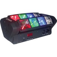
natural_image
Black E-SPOT100 laser beam projector with colorful LED and green lens (no visible text or symbols on device body)MANUAL
DMX Channel Table - p. 2
EN - Instruction Manual - p. 4
| 15CH FUNCTION DMX VAL- | UE | DESCRIPTION | |
| 1 Pan | 0-255 | ||
| 2 Pan | Fine 0-255 | ||
| 3 Tilt | 0-255 | ||
| 4 Tilt | Fine 0-255 | ||
| 5 P/T | Speed 0-255 Speed from fast to slow | ||
| 6 Dimmer | 0-255 Dimmer from dark to bright | ||
| 7 Strobe | 0 No Function | ||
| 1-255 Strobe from slow to fast | |||
| 8 Color | 0--15 | White | |
| 16--31 | Color 1 | ||
| 32--47 | Color 2 | ||
| 48--63 | Color 3 | ||
| 64--79 | Color 4 | ||
| 80--95 | Color 5 | ||
| 96--111 | Color 6 | ||
| 112--127 | Color 7 | ||
| 128-191 | Color Wheel clockwise rotation from fast to slow | ||
| 192-255 | Color Wheel counter-clockwise rotation from slow to fast | ||
| 9 Gobo | 0-7 | White | |
| 8--15 | Gobo 1 | ||
| 16-23 Gobo 2 | |||
| 24-31 Gobo 3 | |||
| 32-39 Gobo 4 | |||
| 40-47 Gobo 5 | |||
| 48-55 Gobo 6 | |||
| 56-63 Gobo 7 | |||
| 64-73 Gobo 7 shake from slow to fast | |||
| 74-83 Gobo 6 shake from slow to fast | |||
| 84-93 Gobo 5 shake from slow to fast | |||
| 94-103 | Gobo 4 shake from slow to fast | ||
| 104-113 | Gobo 3 shake from slow to fast | ||
| 114-123 | Gobo 2 shake from slow to fast | ||
| 124-127 | Gobo 1 shake from slow to fast | ||
| 128-191 | Gobo Wheel clockwise rotation from fast to slow | ||
| 192-255 | Gobo Wheel counter-clockwise rotation from slow to fast | ||
| 10 | Prism | 0-7 | Prism off |
| 8-127 Prism on | |||
| 128-255 | Prism rotation from slow to fast | ||
| 11 | LED ring Macro Function | 0-7 | OFF |
| 8-25 | Red | ||
| 26-43 Green | |||
| 44-61 Blue | |||
| 62-79 Red+Green | |||
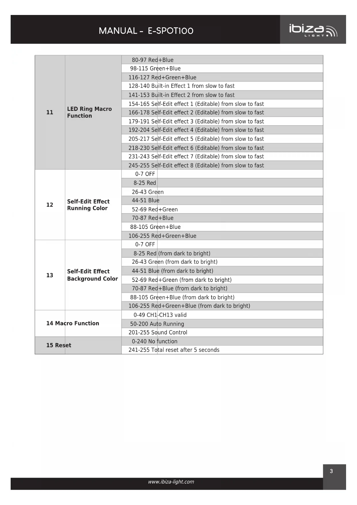
| 11 | LED Ring Macro Function | 80-97 Red+Blue | |
| 98-115 Green+Blue | |||
| 116-127 Red+Green+Blue | |||
| 128-140 Built-in Effect 1 from slow to fast | |||
| 141-153 Built-in Effect 2 from slow to fast | |||
| 154-165 Self-Edit effect 1 (Editable) from slow to fast | |||
| 166-178 Self-Edit effect 2 (Editable) from slow to fast | |||
| 179-191 Self-Edit effect 3 (Editable) from slow to fast | |||
| 192-204 Self-Edit effect 4 (Editable) from slow to fast | |||
| 205-217 Self-Edit effect 5 (Editable) from slow to fast | |||
| 218-230 Self-Edit effect 6 (Editable) from slow to fast | |||
| 231-243 Self-Edit effect 7 (Editable) from slow to fast | |||
| 245-255 Self-Edit effect 8 (Editable) from slow to fast | |||
| 12 | Self-Edit Effect Running Color | 0-7 OFF | |
| 8-25 Red | |||
| 26-43 Green | |||
| 44-51 Blue | |||
| 52-69 Red+Green | |||
| 70-87 Red+Blue | |||
| 88-105 Green+Blue | |||
| 106-255 Red+Green+Blue | |||
| 13 | Self-Edit Effect Background Color | 0-7 OFF | |
| 8-25 Red (from dark to bright) | |||
| 26-43 Green (from dark to bright) | |||
| 44-51 Blue (from dark to bright) | |||
| 52-69 Red+Green (from dark to bright) | |||
| 70-87 Red+Blue (from dark to bright) | |||
| 88-105 Green+Blue (from dark to bright) | |||
| 106-255 Red+Green+Blue (from dark to bright) | |||
| 14 Macro Function | 0-49 CH1-CH13 valid | ||
| 50-200 Auto Running | |||
| 201-255 Sound Control | |||
| 15 Reset | 0-240 No function | ||
| 241-255 Total reset after 5 seconds | |||
DMX-CONTROLLED LED SPOT + RING MOVING HEAD
INSTRUCTION MANUAL
CONTENTS OF THE CARTON:
- 1 x Moving head
- 1x Mains lead
- 1x omega bracket
- 1x User Manual
UNPACKING INSTRUCTIONS
Immediately upon receiving a fixture, carefully unpack the carton, check the contents to ensure that all parts are present and have been received in good condition. Notify the freight company immediately and retain packing material for inspection if any parts appear to be damaged from shipping or the carton itself shows signs of mishandling. Keep the carton and all packing materials. In the event that a fixture must be returned to the factory, it is important that the fixture be returned in the original factory box and packing.
EXPLANATION OF SYMBOLS
The triangle containing a lightning symbol is used to indicate whenever your health is at risk (due to electrocution, for example).
An exclamation mark in a triangle indicates particular risks in handling or operating the appliance.
UK CA The unit complies with UK standards
For indoor use only
Protection class I. Requires an earth connection
Minimum distance between the appliance and other objects
Don't stare into the light beam

CAUTION DO NOT OPEN THE HOUSING SHOCK HAZARD
IMPORTANT SAFETY INSTRUCTIONS AND DANGER WARNINGS
- Please read these instructions carefully, they include important information about the installation, usage and maintenance of this product.
- Please keep this User Guide for future reference. If you sell the unit to another user, be sure that he also receives this instruction booklet.
- Always make sure that you are connecting to the proper voltage, and that the line voltage you are connecting to is not higher than that stated on the decal or rear panel of the fixture.
- This product is intended for indoor use only!
- It is essential that the device is earthed. A qualified person must carry out the electric connection.
- To prevent risk of fire or shock, do not expose fixture to rain or moisture. Make sure there are no flammable materials close to the unit while operating.
- The unit must be installed in a location with adequate ventilation, at least 0.5m from adjacent surfaces. Be sure that no ventilation slots are blocked.
- Always disconnect from power source before servicing or replacing fuse and be sure to replace with same fuse size and type.
- Secure fixture to fastening device using a safety chain. Never carry the fixture solely by its head. Use its carrying handles.
• Maximum ambient temperature (Ta) is 35^ C. Do not operate the fixture at temperatures higher than this.
- The surface temperature of the unit may reach up to 120°C. DO NOT TOUCH the housing barehand during its operation. Turn off the power and allow about 15 minutes for the unit to cool down before replacing or servicing.
- DO NOT OPEN the unit within 5 minutes after switching off.
- In the event of a serious operating problem, stop using the unit immediately. Never try to repair the unit by yourself. Repairs carried out by unskilled people can lead to damage or malfunction. Please contact the nearest authorized technical assistance center. Always use the same type of spare parts.
- Don't connect the device to a dimmer pack.
• Make sure the power cord is never crimped or damaged. - Never disconnect the power cord by pulling or tugging on the cord.
- Avoid direct eye exposure to the light source while it is on.
• The product is for decorative purposes only and not suitable as a household room illumination. - The light source of this luminaire is not replaceable. When it reaches the end of its life time, the whole unit must be discarded.
- Caution: Flashing lights can cause epileptic seizures in sensitive people.
DISCONNECT DEVICE: The power outlet must be installed near the equipment and be easily accessible.
INSTALLATION
The unit should be mounted via its screw holes on the bracket. Always ensure that the unit is firmly fixed to avoid vibration and slipping while operating. Always ensure that the structure to which you are attaching the unit is secure and able to support a weight of 10 times of the unit's weight. Also always use a safety cable that can hold 12 times the weight of the unit when installing the fixture.
Never stand directly below the device when mounting, removing or servicing the fixture. This fixture may be mounted in any position provided there is adequate room for ventilation.
The LED moving head provides a unique mounting bracket assembly that integrates the bottom of the base, the included 'omega bracket' and the safety cable rigging point in one unit. When mounting this fixture on a truss, be sure to use an appropriate clamp with the included omega bracket using a M10 screw fitted through the center hole of the 'omega bracket'. As an added safety measure, be sure to attach at least one properly rated safety cable to the fixture using one of the safety cable rigging points integrated in the base assembly.
FUSE REPLACEMENT
- With a flat head screwdriver wedge the fuse holder out of its housing.
- Remove the damaged fuse from its holder and replace with exactly the same type of fuse.
- Insert the fuse holder back in its place and reconnect power.
- The fuse is located inside this compartment. Remove using a flat head screwdriver.
FIXTURE LINKING
You will need a serial data link to run light shows of one or more fixtures using a DMX-512 controller or to run synchronized shows on two or more fixtures set to a master/slave operating mode. The combined number of channels required by all fixtures on a serial data link determines the number of fixtures that the data link can support.
flowchart
graph TD
    A["Console"] --> B["Light1"]
    A --> C["Light2"]
    A --> D["Light3"]
    C --> E["..."]
    D --> F["..."]
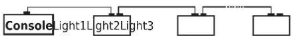
Important: Fixtures on a serial/data link must be daisy chained in one single line. Maximum recommended serial data link distance: 100 meters. Maximum recommended number of fixtures on a serial data link: 32 fixtures
CABLE CONNECTORS
Cabling must have a male XLR connector on one end and a female XLR connector on the other end.
DMX CONNECTOR CONFIGURATION
Termination reduces signal errors. To avoid signal transmission problems and interference, it is always advisable to connect a DMX signal terminator. Resistance 120 ohm 1/4w between pin 2 (DMX-) and pin 3 (DMX+) of the last fixture.

text_image
INPUT COMMON DMX+ DMX- OUTPUTCAUTION
Do not allow contact between the common and the fixture's chassis ground. Grounding the common can cause a ground loop, and your fixture may perform erratically. Test cables with an ohm meter to check correct polarity and to make sure the pins are not grounded or shorted to the shield or each other.
SETTING UP A DMX SERIAL DATA LINK
- Connect the (male) 3 pin connector side of the DMX cable to the output (female) 3 pin connector of the controller.
- Connect the end of the cable coming from the controller which will have a (female) 3 pin connector to the input connector of the next fixture consisting of a (male) 3 pin connector.
- Then, proceed to connect from the output as stated above to the input of the following fixture and so on.
MASTER/SLAVE FIXTURE LINKING
- Connect the (male) 3 pin connector side of the DMX cable to the output (female) 3 pin connector of the first fixture.
- Connect the end of the cable coming from the first fixture which will have a (female) 3 pin connector to the input connector of the next fixture consisting of a (male) 3 pin connector. Then, proceed to connect from the output as stated above to the input of the following fixture and so on
Often, the set up for Master-Slave and Stand-alone operation requires that the first fixture in the chain be initialized for this purpose via either settings in the control panel or DIP-switches. Secondarily, the fixtures that follow may also require a slave setting. Please consult the "Operating Instructions" section in this manual for complete instructions for this type of setup and configuration.
OPERATING INSTRUCTIONS
NAVIGATION THROUGH THE CONTROL PANEL
Access control panel functions using the four panel buttons located directly underneath the LCD Display..
Button Function
| MENU Used to access the menu or to return to a previous menu option |
UP Scrolls through menu options in ascending order
DOWN Scrolls through menu options in descending order
ENTER Used to select and store the current menu or option within a menu


MENU

UP

DOWN

ENTER
When a menu function is selected, the display will show immediately the first available option for the selected menu function. To select a menu item, press
MENU MAP
Press the
DISPLAY EXPLANATION
| Addr A001-A512: DMX Address 001-512 | |
| CHnd 15CH: DMX Channel | |
| SLnd DMX/Auto/Sound: Running Mode | |
| Pan | YES, NO: Pan Reverse |
| Tilt | YES, NO: Tilt Reverse |
| SEne | 0-100: Sound sensitivity |
| LED | Backlight ON, OFF |
| DISP | YES, NO: Display reverse |
| TEMP XXX: Device's temperature | |
| Ver | V100: Software Version |
| Faet | YES, NO: Restore to factory set |
OFFSET:
In the Main menu, press ENTER for 5 seconds to access the Offset MENU
| Pan 0-127 Pan offset | ||
| -1-(-127) | ||
| Tilt 0-127 Tilt offset | ||
| -1-(-127) | ||
| Color 0-127 Color offset | ||
| -1-(-127) | ||
| Gobo 0-127 Gobo offset | ||
| -1-(-127) |
CARE
Before cleaning the unit, disconnect it if from the mains. Do not use aggressive cleaning agents. Use a clean cloth to wipe any dust or dirt from the product. We are not liable for damage arising from incorrect handling, improper use or wear and tear. We reserve the right to make technical modifications.
SPECIFICATIONS
Power supply....100-240\~50/60Hz
Consumption....150W
LED ....Spot: 1x white 100W LED
Wash ring: 12 x 0.3W 5050 RGB 3-in-1 LEDs
Spot angle....13°
DMX channels 15
Operation modes....Auto, master-slave, DMX512, sound control
Movement....Pan: 540° / Tilt: 190° (16-bit)
Colour wheel....7 colours + open, rainbow flow effect
Gobo 7 gobos + blank, gobo shake, gobo flow effect
Prism....6 facet rotating prism
Dimmer 0-100% linear
Strobe 25 flashes/sec.
Dimensions 240 x 145 x 310mm
Weight....4kg
MANUEL D'UTILISATION
LYRE SPOT + ANNEAU WASH A LED BLANCHE AVEC CONTRÔLE DMX
CONTENU DE L'EMBALLAGE:
REPLACEMENT DU FUSIBLE
Consommation....130W
LED ....1 LED blanche de 100W
Stroboscope....20 flashes/sec.
Dimensions 235 x 150 x 320mm
Poids 4.06kg
flowchart
graph TD
    A["ConsoleLight1"] --> B["Light2Light3"]
    B --> C[" "]
    B --> D[" "]
Wash ring: 12 x 0.3W 5050 RGB 3-in-1 led's
Afstraalhoek....13°
DMX kanalen....15
Werkmodi....Auto, master-slave, DMX512, geluidscontrole
flowchart
graph TD
    A["ConsoleLight1"] --> C
    B["Light2Light3"] --> C
    C --> D
    C --> E
    C --> F
Dimmer 0-100% lineare
Stroboscopico 25 flash/sec.
Dimensioni 240 x 145 x 310 mm
Peso 4 kg
Resistance 120 ohm 1/4w between pin 2 (DMX-) and pin 3 (DMX+) of the last fixture.
CUIDADO
Stroboscop....25 flashes/sec.
Dimensiuni....240 x 145 x 310mm
Greutate....4kg
Resistance 120 ohm 1/4w between pin 2 (DMX-) and pin 3 (DMX+) of the last fixture.
FÖRSIKTIGHET
| DISPLAY FÖRKLARING | |
| Addr A001-A512: DMX Address 001-512 | |
| CHnd 15CH: DMX Channel | |
| SLnd DMX/Auto/Sound: Running Mode | |
| Pan YES, NO: Pan Reverse | |
| Tilt | YES, NO: Tilt Reverse |
| SEne | 0-100: Sound sensitivity |
| LED | Backlight ON, OFF |
| DISP | YES, NO: Display reverse |
| TEMP XXX: Device's temperature | |
| Ver | V100: Software Version |
| Faet | YES, NO: Restore to factory set |
OFFSET:
Resistance 120 ohm 1/4w between pin 2 (DMX-) and pin 3 (DMX+) of the last fixture.
PRZESTROGA
Resistance 120 ohm 1/4w between pin 2 (DMX-) and pin 3 (DMX+) of the last fixture.
| DISPLAY AÇIKLAMA | |
| Addr A001-A512: DMX Address 001-512 | |
| CHnd 15CH: DMX Channel | |
| SLnd DMX/Auto/Sound: Running Mode | |
| Pan YES, NO: Pan Reverse | |
| Tilt | YES, NO: Tilt Reverse |
| SEne | 0-100: Sound sensitivity |
| LED | Backlight ON, OFF |
| DISP | YES, NO: Display reverse |
| TEMP XXX: Device's temperature | |
| Ver | V100: Software Version |
| Faet | YES, NO: Restore to factory set |
OFFSET
LED Spot: 1x beyaz 100W LED
Yıkama halkası: 12 x 0,3W 5050 RGB 3'ü 1 arada LED
Spot açısı 13°
DMX kanalları 15
natural_image
Pixelated black-and-white image of a large letter 'L' with a rectangular cutout, resembling a stylized letter or symbol (no text or symbols present)
View the product on our website

Any question or problem?
Contact us via facebook

IBIZALIGHTSOUND
Follow us on Instagram

Assembled in PRC • Designed by LOTRONIC S.A. • Rue F. Englert 17 • Bt 2 • 1480 Tubize • Belgium info@lotronic.net
https://ibizashop.eu/
©Copyright LOTRONIC 2024