IB 108 L2P - Steam cleaner Kärcher - Free user manual and instructions
Find the device manual for free IB 108 L2P Kärcher in PDF.
User questions about IB 108 L2P Kärcher
0 question about this device. Answer the ones you know or ask your own.
Ask a new question about this device
Download the instructions for your Steam cleaner in PDF format for free! Find your manual IB 108 L2P - Kärcher and take your electronic device back in hand. On this page are published all the documents necessary for the use of your device. IB 108 L2P by Kärcher.
USER MANUAL IB 108 L2P Kärcher
natural_image
Line drawing of a KARCHER professional gas purifier with control panel and wheels (no text or symbols on the device itself)Deutsch 4
English 11
Français 18
Italiano 26
Nederlands 34
Español 41
Português 49
Dansk 57
Norsk 63
Svenska 70
Suomi 77
Ελληνικά 84
Türkçe 92
Русский 99
Magyar 108
Čeština 115
Slovenščina 122
Polski 129
Românește 136
Slovenčina 144
Hrvatski 151
Srpski 158
Български 165
Eesti 174
Latviešu 181
Lietuviškai 188
Українська 195
中文 203
العربيya 209
natural_image
Technical line drawing of a handheld electronic device with labeled component (no text or symbols present)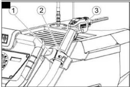
natural_image
Technical line drawings of a two-hotor industrial robotic device, showing front and side views (no text or symbols)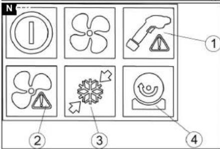
natural_image
Technical line drawing of a wheeled vehicle with wheels and a handle (no text or symbols)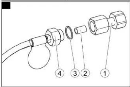
Inhalt
| Frequenz Hz 50...6 | 0 |
1.574-xxx (IB 10/8 L2P)
H. Jenner
Chairman of the Board of Management
S. Reiser
Director Regulatory Affairs & Certification
71364 Winnenden (Germany)
Tel.: +49 7195 14-0
Fax: +49 7195 14-2212
Winnenden, 2021/02/01
Contents
General notes.... 11
Intended use.... 11
Function.... 11
Environmental protection.... 11
Safety instructions.... 11
Safety devices 13
Accessories and spare parts.... 13
Scope of delivery.... 13
Control elements 13
Initial startup 13
Operation.... 14
Ending operation 15
Transport 16
Storage.... 16
Care and service 16
Troubleshooting guide 16
Warranty 17
Accessories 17
Technical data 17
Declaration of Conformity.... 18
General notes
Read the original instructions before using the device for the
first time and act in accordance with it. Keep the original instructions for future reference or for future owners.
Intended use
- The device is used to remove dirt with dry ice pellets that are accelerated by an air jet.
- The dry ice pellets are produced in the device. This requires liquid carbon dioxide from a dip tube bottle.
- The device may not be operated in a potentially explosive atmosphere.
- The minimum air exchange specified in the "Technical data" section must be observed at the operating location.
- The casing of the device may only be removed by KÄRCHER Customer Service for maintenance purposes.
CO_2 quality
To ensure trouble-free operation, the carbon dioxide used must at least comply with the following specifications:
- Carbon dioxide technical, class 2.5 or better
- Purity ≥ 99.5%
• Water content (H _2 O) ≤ 250 ppm
• NVOC (oil and fat) ≤ 2 ppm
Function
Carbon dioxide snow is created via decompression of liquid carbon dioxide. The gaseous carbon dioxide that also arises is carried away from the workplace via the exhaust hose.
The carbon dioxide snow is pressed into dry ice pellets in the device.
Compressed air reaches the jet gun via a solenoid valve. The air pressure is controlled by an on-site pressure reducer.
When the trigger of the jet gun is activated, the valve opens and the air jet emerges from the jet gun. Dry ice pellets are additionally dosed into the air jet via a dosing device.
The dry ice pellets hit the surface to be cleaned and remove the dirt. The -79 °C cold dry ice pellets also create thermal stresses between the dirt and the object to be cleaned, which also contribute to the loosening of the dirt. In addition, the dry ice immediately turns into gaseous carbon dioxide when it hits the surface, thus taking up 700 times its volume. Dirt penetrated by the dry ice is blown away as a result.
Environmental protection
The packing materials can be recycled. Please dispose of packaging in accordance with the environmental regulations.
Electrical and electronic appliances contain valuable, recyclable materials and often components such as batteries, rechargeable batteries or oil, which - if handled or disposed of incorrectly - can pose a potential threat to human health and the environment. However, these components are required for the correct operation of the appliance. Appliances marked by this symbol are not allowed to be disposed of together with the household rubbish.
Notes on the content materials (REACH)
Current information on content materials can be found at: www.kaercher.com/REACH
Safety instructions
The device may only be operated by persons who have read and understood these
operating instructions. In particular, all safety instructions must be observed. Store these operating instructions so that they are available to the operator at all times.
The operator of the unit must carry out a risk assessment on site and ensure that operators are instructed.
Hazard levels
△DANGER
- Indication of an imminent threat of danger that will lead to severe injuries or even death.
⚠ WARNING
- Indication of a potentially dangerous situation that may lead to severe injuries or even death.
△CAUTION
- Indication of a potentially dangerous situation that may lead to minor injuries.
ATTENTION
- Indication of a potentially dangerous situ- securely.
ation that may lead to damage to property.
Symbols on the unit
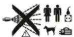
Danger from flying dry ice pellets.
Do not point the jet gun at people. Remove third parties from the operating loca-
tion and keep them away (e.g. via barriers) during operation. Do not touch the nozzle or the dry ice jet during operation.
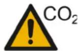
Risk of suffocation from carbon dioxide.
During operation, the carbon dioxide content of the air at the workplace increas-
es.
Make sure there is sufficient air exchange at the workplace.
Lay the exhaust hose outdoors, for example, so that nobody is endangered by carbon dioxide.
Note: Carbon dioxide is heavier than air. Make sure that carbon dioxide does sink to lower-lying areas, for example by flowing from the outside into a basement below the workshop (flows).
For longer jet work (longer than 10 minutes per day) and especially in small rooms (less than 300 m ^4 ), we recommend wearing a carbon dioxide warning device.
Signs of high levels of carbon dioxide:
3...5%: Headache, high breathing rate.
7...10%: Headache, nausea, possibly unconsciousness.
If these symptoms occur, switch off the device immediately and get some fresh air.
Before continuing work, improve ventilation or use a breathing apparatus.
Carbon dioxide is heavier than air and collects in confined spaces, lower-lying spaces or in closed containers. Ensure adequate ventilation at the workplace.
Observe the safety data sheet from the carbon dioxide supplier.
Risk of injury, risk of damage from electrostatic charging. The cleaning object can become electrostatically charged during the cleaning process.
Ground the object to be cleaned and keep it grounded it until the cleaning process is complete.
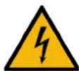
Risk of injury from electric shock.
Do not open the device. Work on the device may only be performed by KÄRCHER Customer Service.
Risk of injury from cold burns.
Dry ice has a temperature of -79 °C. Do not touch the dry ice or cold parts of the unit.
Risk of injury from carbon dioxide bottle falling over, Danger of suffocation due to carbon dioxide
Attach the carbon dioxide bottle

Risk of injury from flying dry ice pellets and dirt particles. Wear safety goggles.
Danger of hearing damage.
Wear hearing protection.

Risk of injury from flying dry ice pellets and dirt particles.
Wear protective gloves according to EN 511.

Risk of injury from flying dry ice pellets and dirt particles.
Wear long-sleeved protective clothing.
Caution! Permanent malfunctions possible.
Traces of fat or oil interfere with the formation of dry ice snow in the device. Do not use grease, oil or other lubricants on the connection nozzle or on the thread of the carbon dioxide bottle or the carbon dioxide hose.
General safety instructions
△DANGER
Risk of injury
The device may start up unexpectedly. Unplug the mains plug from the power socket before working on the device.
Risk of injury
Dry ice and cold device parts can cause cold burns on contact with the skin.
Wear cold protection clothing or allow the device to warm up before working on the device.
Never put dry ice in your mouth.
Risk of injury
The dry ice jet can be dangerous if used improperly.
Do not direct the dry ice jet at persons, live electrical equipment or at the device itself. Do not aim the dry ice jet at yourself or others, e.g. to clean clothes or shoes.
Risk of injury
Light objects can be blasted away by the dry ice jet.
Fix light objects in place before starting cleaning.
Risk of asphyxiation
Increased concentration of carbon dioxide in the air you breathe can lead to death from suffocation.
Make sure that no exhaust gases are emitted close to air vents.
Provide adequate ventilation in the workplace and ensure that the exhaust gases are properly discharged.
△WARNING
Risk of injury
The recoil force of the jet gun can throw you off balance.
Find a safe place to stand and hold the jet gun firmly before you pull the trigger.
Risk of injury
Dry ice pellets and dirt particles can hit and injure people.
Do not use the device when other people are within range unless they are wearing protective clothing.
Do not use the device if a power cable or important parts of the device are damaged, e.g. safety devices, abrasive hose, jet gun.
Safety instructions for gas bottles
△DANGER
Risk of bursting, risk of suffocation
Gas bottles can burst if they become too hot or if they are mechanically damaged. Leaking carbon dioxide can cause death by suffocation.
Protect gas bottles from excessive heat, fire, dangerous corrosion, mechanical damage and unauthorized access.
Store gas bottles so that no escape routes are restricted.
Do not store gas bottles in underground rooms, on and at stairs, in hallways, corridors and garages.
Do not store gas bottles together with flammable materials.
Store gas bottles upright.
Secure gas bottles against tipping over or falling.
Close the bottle valve before transporting gas bottles.
Transport gas bottles with a gas bottle cart or a vehicle and secure the bottles against falling.
Pull on the protective cover before lifting the gas bottle to check that the protective cover is securely in place.
Secure the gas bottle at the point of use against falling over.
Do not open the bottle valve to check the pressure.
Open and close the bottle valve only by hand without the aid of tools.
Check the bottle valve/device connection for leaks.
Close the bottle valve during work breaks and at the end of work to prevent uncontrolled gas escaping.
Only empty gas bottles so far that a small residual pressure remains in the bottle in order to prevent foreign matter from entering.
When the gas bottle has been emptied to the residual pressure, first close the bottle
valve before unscrewing the extraction device. The gas bottle still has considerable residual pressure.
Before returning it, screw the locking nut and the protective cover onto the gas bottle. If the gas escapes uncontrolled, close the bottle valve. If the gas emission cannot be stopped, take the bottle outside or leave the room, lock the access and only enter and ventilate the room if a concentration measurement rules out a danger.
Regulations and guidelines
In the Federal Republic of Germany, the following regulations and guidelines apply to the operation of this system (available from Carl Heymanns Verlag KG, Luxemburger Straße 449, 50939 Cologne):
- DGUV R 100-500 Working with blasting machines
- DGUV 113-004 Working in confined spaces
- DGUV 113-004 Use of protective clothing
• DGUV 113-004 Use of protective gloves
• DGUV 113-004 Working with jet units
• DGUV 213-056 Gas warning unit - VDMA 24389 Systems for dry ice jet - safety requirements
Switching off in the event of an emergency
- Release the trigger of the jet gun.
- Turn the program switch to "0/OFF".
- Close the stop valve on the carbon dioxide bottle.
- Shut off the compressed air supply.
Safety devices
△CAUTION
Missing or modified safety devices
Safety devices are provided for your own protection.
Never modify or bypass safety devices.
Safety lever
The safety lever prevents unintentional activation of the jet gun. The trigger can only be operated when the safety lever has been raised beforehand.
Accessories and spare parts
Only use original accessories and original spare parts. They ensure that the appliance will run fault-free and safely. Information on accessories and spare parts can be found at www.kaercher.com.
Protective clothing
Full-view safety goggles, anti-fog, part no.: 6.321-208.0
Cold protection gloves with anti-slip profile, category III according to EN 511, part no.: 6.321-210.0
Hearing protection with headband, part no.: 6.321-207.0
Scope of delivery
Check the contents for completeness when unpacking. If any accessories are missing or in the event of any shipping damage, please notify your dealer.
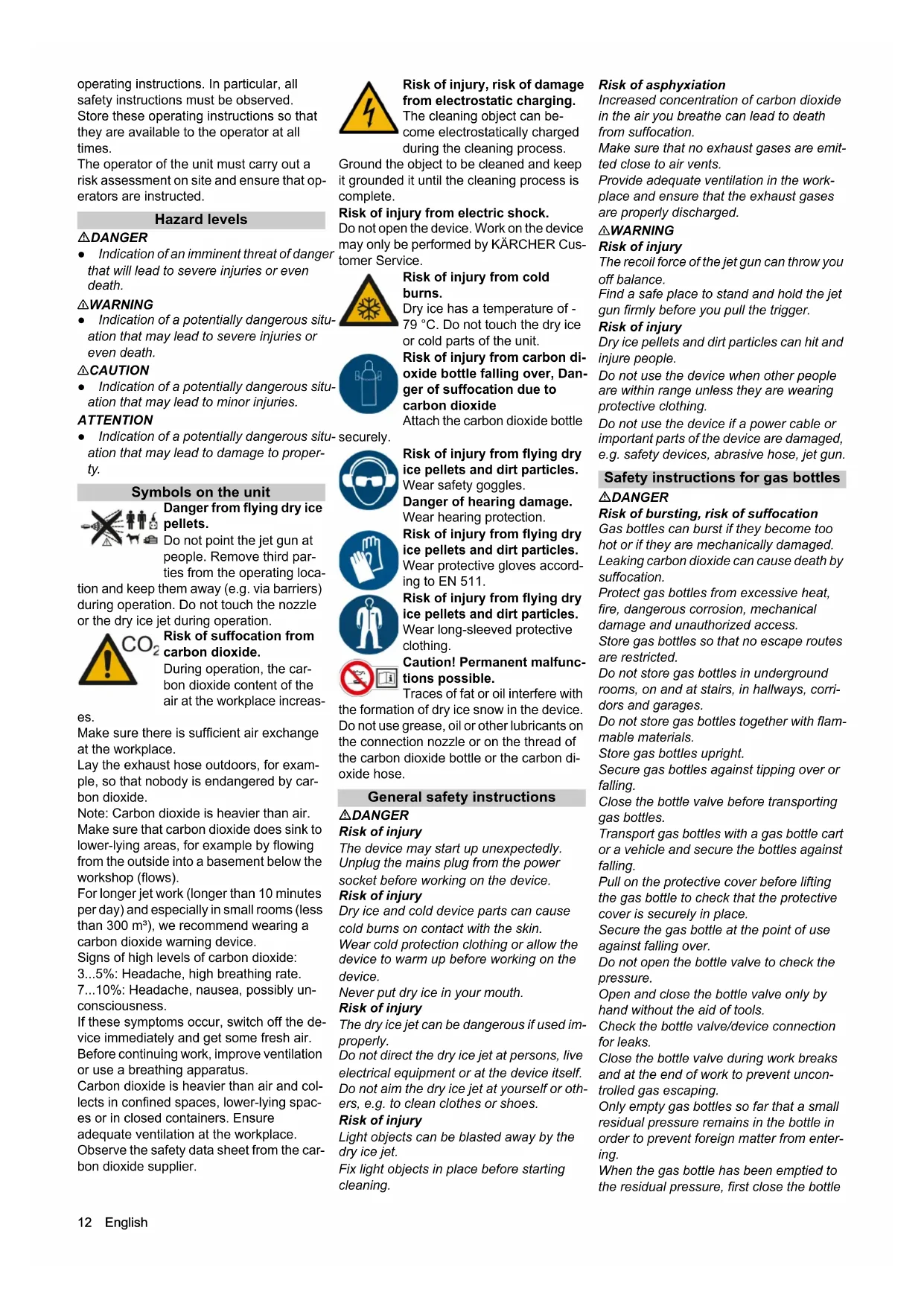
Control elements
Illustration A
①Steering roller with parking brake
② Abrasive hose coupling
③Control cable coupling
④Control panel
⑤Push handle
⑥Holder for jet gun
⑦Storage area
⑧ Nozzle holder
⑨Display
⑩Program switch
⑪Fault indication pellet dosing
– Lights up red: The drive motor of the dosing device is blocked
- Flashes red: The drive motor of the dosing device is overheated
⑫Fault indication pellet generation
– Lights up red: The drive motor for pellet production is blocked
⑬ Compressed air supply fault indicator
- Lights up red: Compressed air supply has too little pressure
- Flashes red: The internal pressure is too high
⑭Voltage supply indicator lamp
– Lights up green: Voltage supply OK
⑮ Compressed air indicator light
– Lights up green: Compressed air supply OK.
⑯Jet gun fault indicator
- Lights up yellow: The trigger is fastened (e.g. cable tie)
- Flashes yellow: no jet gun connected to the device
⑰Jet nozzle
⑱Jet gun
⑲Compressed air / pellets button with indicator light
- Lights up red: Compressed air jet
- Off: Pellet jet
⑳Trigger
②1 Safety lever
②Retaining cone
②3Abrasive hose
⑳Bottle connection
⑲Screw plug
②6 Copper sealing ring
27Carbon dioxide filter
⑳Screw flange
⑲Bottle connection seal (order number 6.574-316.0)
③0Carbon dioxide immersion pipe bottle (not included in the scope of delivery)
③1Carbon dioxide hose
③2Carbon dioxide bottle retaining belt
③3Homebase retaining rail
③4Hose/cable holder with rubber tensioner
③5 Opening for resetting the motor circuit breaker
36Handle
③7 Compressed air connection
③8 Storage space for carbon dioxide bottle
⑲Carbon dioxide exhaust hose
④0Mains connection cable with mains plug
④1Holder for abrasive hose
④2Drain tap for condensation water
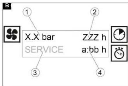
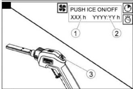
Display
Program switch at level 1 ... 3: Illustration B
①Jet pressure
②Total operating time
③Customer Service visit is due
④ Blasting jet time since last reset
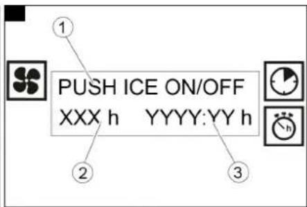
Program switch in the reset position: Illustration C
①To reset the jet time, press the compressed air / pellets button
②Period of time until the next Customer Service visit
③ Blasting jet time since last reset
Initial startup
△DANGER
Risk of injury
Dry ice pellets can escape from damaged components and cause injuries. Before initial startup, check all components of the device, especially the abrasive hose, to ensure that they are in good condition. Replace damaged assemblies with flawless ones. Clean soiled assemblies and check that they are working properly.
ATTENTION
Risk of damage
Condensation water can drip from the device casing onto the floor. Do not operate the device on surfaces that are sensitive to moisture.
- Open the drain tap and drain the condensation water that has collected in the device.
- Close the drain tap.
- Store the device on a level and flat surface.
- Block the steering rollers with the parking brakes.
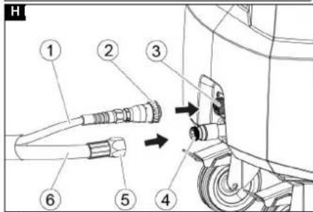
- Connect the abrasive hose to the coupling on the device.
Illustration H
① Control cable
②Union nut
③Control cable coupling
④ Abrasive hose coupling
⑤Union nut
⑥ Abrasive hose
- Unscrew the union nut of the abrasive hose and slightly tighten it with an open-end wrench.
- Plug the control cable into the device.
- Screw on the union nut of the control cable and tighten by hand.
- Insert the jet gun with the retaining cone into the holder on the device.
△DANGER
Risk of asphyxiation
Carbon dioxide escapes from the exhaust hose. From a concentration of 8 percent by volume in the breath, carbon dioxide leads to unconsciousness, respiratory arrest and death. The maximum workplace concentration is 0.5%. Carbon dioxide is heavier than air and collects in pits, basements and depressions.
Lay the exhaust hose so that nobody is endangered by the escaping carbon dioxide.
Note: Carbon dioxide is heavier than air. Make sure that carbon dioxide does sink to lower-lying areas, for example by flowing
from the outside into a basement below the workshop (flows).
- Lay the exhaust hose outdoors or connect it to an extraction device.
Changing the jet nozzle
The jet nozzle on the jet gun can be exchanged in order to adapt the device to the material and degree of contamination of the object to be cleaned.
DANGER
Risk of injury
The unit can start unintentionally and cause injuries and cold burns from the jet of dry ice pellets.
Set the program switch to "0/OFF" before removing the nozzle.
⚠ WARNING
Risk of injury
Immediately after use, the nozzle is very cold and can cause cold burns if touched. Let the nozzle thaw before replacing it or wear protective gloves.
ATTENTION
Risk of damage
Do not operate the device if no jet nozzle is attached to the jet gun.
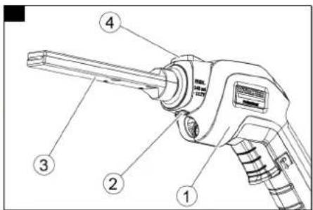
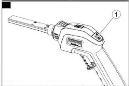
- Press the unlocking button down and pull the jet nozzle out of the jet gun. Illustration D
①Jet gun
②Pin
③Jet nozzle
④ Unlocking button
- Press the other jet nozzle into the jet gun until it clicks into place.
Note: The jet nozzle is correctly engaged when the pin no longer protrudes from the casing. The jet nozzle can be rotated to the desired orientation.
Connecting compressed air
Note
For trouble-free operation, the compressed air must have a low moisture content (maximum 5% relative humidity, dew point below 0^ C). The compressed air must be free of oil, dirt and foreign bodies.
The compressed air must be dry and oil-free, at least one aftercooler and a separator must be connected downstream of the compressor.
The compressed air supply must be equipped with an on-site pressure reducer.
-
Don personal protective equipment.
-
Connect a compressed air hose to the compressed air connection on the device.
-
Slowly open the on-site compressed air stop valve.
Connecting the carbon dioxide bottle
Requirements for the CO_2 supply:
- CO_2 bottle with dip tube for withdrawing liquid CO_2 .
Note
CO _2 bottles with a dip tube (also called a riser) are usually marked with a large "T" on the bottle or the back of the bottle.
In some cases, the dip tube is additionally symbolised by a vertical colour line on the bottle.
- The CO_2 quality must correspond to the specifications in the chapter "Intended use".
ATTENTION
Malfunctions
A residual pressure valve or check valve connected to the CO_2 bottle prevents extraction of the required CO_2 amount. If a CO2 bottle with residual pressure valve is used, the ABS residual pressure valve (order number 2.574-006.0), available as an accessory, must be installed between the bottle and the unit.
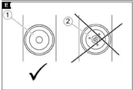
Illustration E
①CO 2 bottle without residual pressure valve
②CO 2 bottle with residual pressure valve As the temperature rises, the effectiveness of pellet production decreases and a larger proportion of carbon dioxide is released in gaseous form via the exhaust hose. Store carbon dioxide bottles as cool as possible (below 31 °C) and protect them from heat, solar radiation and heat during operation.
- Push the device onto a level, stable surface.
- Apply the parking brakes on both steering rollers.
- Open both straps for the carbon dioxide bottle.
- Place the carbon dioxide bottle on the storage space on the device.
Note: If the carbon dioxide bottle is transported on a bottle cart, the front edge of the floor area on the transport cart can be placed on the surface of the device. The bottle can then be moved from the trolley to the base by rotating it.
- Place both straps around the carbon dioxide bottle, lock and tighten.
- Unscrew the protective cover from the carbon dioxide bottle.
ATTENTION
Malfunctions possible
Traces of fat interfere with the formation of dry ice snow in the device.
Check the connection nozzle and thread of the carbon dioxide bottle and the carbon dioxide hose and, if necessary, clean them before connecting to the device.
Make sure that an undamaged seal is inserted between the bottle and the bottle connection.
- For bottles with residual pressure valve, attach the ABS residual pressure valve (order number 2.574-006.0), available as an accessory, to the carbon dioxide bottle. Follow the separate instructions enclosed with the adapter.
- Connect the bottle connection to the carbon dioxide filter on the carbon dioxide bottle.
Make sure that a sealing ring bottle connection in perfect condition is inserted between the screw flange and the carbon dioxide bottle.
- Lightly tighten the narrow union nut of the screw flange with an open-end wrench or ring spanner (e.g. 6.574-337.0). Hold the wide union nut with an open-end wrench to prevent the carbon dioxide hose from twisting.
ATTENTION
Do not put torsion (twist) on the carbon dioxide hose, otherwise it may be damaged.
Establishing the voltage supply
△DANGER
Risk of injury from electric shock
The power socket used must be installed by an electrician and comply with IEC 60364-1.
The device may only be connected to a voltage supply with protective earth.
The power socket used must be easily accessible and at a height of between 0.6 m and 1.9 m above the floor.
The power socket used must be within sight of the operator.
The device must be protected by an error current circuit breaker, 30 mA.
Check the mains connection of the device for damage before each use. Do not operate the device with a damaged power cable. Have a damaged cable replaced by a qualified electrician.
The extension cable must ensure IPX4 protection and the cable design must at least comply with H 07 RN-F 3G1.5.
Unsuitable extension cables can be dangerous. If an extension cable is used, it must be suitable for outdoor use and the connection must be dry and above the ground. It is recommended to use a cable drum that holds the socket at least 60 mm above the floor.
- Plug the mains plug into the socket.
Reset jet time
To account for working hours, the jet time counter can be reset to 0 before work begins.
- Turn the program switch to the "Reset" position.
Illustration F
①Period of time until the next Customer Service visit
② Blasting jet time since last reset
③ Compressed air/pellets button
2. Press the compressed air/pellets button on the jet gun.
The jet time is reset to 0
Operation
DANGER
Risk of injury
Dry ice pellets flying around can cause injuries or cold burns.
Do not point the jet gun at people. Remove third parties from the operating location and keep them away (e.g. via barriers) during operation. Do not touch the nozzle or the dry ice jet during operation.
-
Carry out all maintenance work from the chapter "Care and maintenance / daily before starting operation".
-
Cordon off the work area to prevent people from entering during operation.
△DANGER
Risk of asphyxiation
Risk of suffocation from carbon dioxide. The dry ice pellets consist of solid carbon dioxide. The carbon dioxide content of the air at the workplace increases when the device is operated.
Lay the exhaust hose outdoors, for example, so that nobody is endangered by carbon dioxide.
Note: Carbon dioxide is heavier than air. Make sure that carbon dioxide does sink to lower-lying areas, for example by flowing from the outside into a basement below the workshop (flows).
For longer jet work (longer than 10 minutes per day) and especially in small rooms (less than 300 m ^3 ), we recommend wearing a carbon dioxide warning device.
Signs of high carbon dioxide concentration in the air you breathe:
3...5%: Headache, high breathing rate.
7...10%: Headache, nausea, possibly unconsciousness.
Turn off the device immediately and seek fresh air at the first signs of these symptoms. Before continuing work, be sure to improve the ventilation measures or use a breathing apparatus.
Observe the safety data sheet provided by the carbon dioxide supplier.
Danger from substances harmful to health.
Substances removed from the object to be cleaned are whirled up as dust. Adhere to the appropriate safety measures if harmful dusts can arise during the cleaning process.
Risk of explosion
A mixture of iron oxide and light metal dust can ignite under unfavourable conditions and generate intense heat.
Never work on light metals and ferrous parts at the same time.
Clean the work area and the extraction device before you work on the respective other material.
-
When working in confined spaces, ensure that there is sufficient air exchange to keep the carbon dioxide concentration in the room air below the dangerous level.
-
Fasten light cleaning objects in position.
△DANGER
Danger of electrostatic discharge
The cleaning object can become electrostatically charged during the cleaning process. The subsequent discharge can cause injuries and damage electronic assemblies. Ground the object to be cleaned and maintain it during the cleaning process.
-
Electrically ground the object to be cleaned.
-
Wear protective clothing, protective gloves, tightly fitting safety goggles and hearing protection.
-
Activate the compressed air supply.
-
Open the stop valve on the carbon dioxide bottle.
-
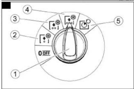
Turn the program switch to level 3. Illustration G
①Program switch
②Level 1
③Level 2
④Level 3
⑤Reset
- Choose a safe place to stand and adopt a safe posture so as not to be unbalanced by the recoil force of the jet gun.
Cleaning with dry ice pellets
- Select operation with pellet jet using the compressed air / pellets button. (The indicator light must not light up.)
Illustration I
① Compressed air / pellets button with indicator light Lights up red: Compressed air jet Off: Pellet jet
- Set the jet pressure on the on-site pressure reducer to the desired value. Maximum pressure: 10 bar. Minimum pressure:
- Level 1: 0.7 bar
- Level 2: 1.4 bar
- Level 3: 2.8 bar
Note
The pressure is shown in the display. If the minimum pressure is not reached or the maximum pressure is exceeded, the display flashes.
-
Point the jet gun away from your body.
-
Push the safety lever of the jet gun upwards and at the same time activate the trigger.
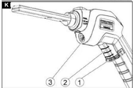
Illustration K
①Safety lever
②Trigger
③ Working light
The working light switches on at the same time as the pellet production.
- Wait until the pellet jet has built up.
ATTENTION
Never operate the device without or with an empty carbon dioxide bottle.
Use the program switch to select a higher level or change the carbon dioxide bottle if no pellets come out of the jet gun after 5 minutes of jet.
- If necessary, turn the program switch back to level 2 or 1.
ATTENTION
Risk of damage
Coarse pellets may possibly escape.
Check the cleaning performance on a non-visible area first to avoid damage.
Note
If there are interruptions in the dry ice stream, increase the blasting pressure or set a lower level on the programme selector switch.
-
Direct the pellet jet at the object to be cleaned and remove the dirt with the jet.
-
Release the trigger.
The pellet jet stops.
The working light goes out after 30 seconds.
- Insert the jet gun with the retaining cone into the holder on the device.
Illustration J
①Holder
②Retaining cone
③Jet gun
- Close the stop valve on the carbon dioxide bottle if the work break lasts longer than 30 minutes.
Compressed air without pellet jet
Loose dirt can be removed with compressed air without dry ice pellets.
- Select operation with compressed air using the compressed air/pellets button. (The indicator light must light up red.) Illustration I
① Compressed air / pellets button with indicator light Lights up red: Compressed air jet Off: Pellet jet
- Push the safety lever of the jet gun upwards and at the same time activate the trigger.
Illustration K
① Safety lever
②Trigger
③Working light
The compressed air flows out of the jet nozzle and the working light is switched on.
-
Direct the compressed air jet at the object to be cleaned and remove the soiling.
-
Release the trigger.
The compressed air jet stops.
The working light goes out after 30 seconds.
-
Insert the jet gun with the retaining cone into the holder on the device.
-
Close the stop valve on the carbon dioxide bottle if the work break lasts longer than 30 minutes.
Ending operation
-
Release the trigger of the jet gun.
-
Close the stop valve on the carbon dioxide bottle.
-
Pull the trigger on the jet gun until no more pellets come out.
-
Turn the program switch to level 1.
-
Shut off the compressed air supply.
-
Operate the trigger on the jet gun until the compressed air has escaped from the device.
-
Turn the program switch to "0/OFF".
-
Pull the mains plug out of the socket.
-
Wind up the power cord, hang it on a hose/cable holder and secure with the rubber tensioner.
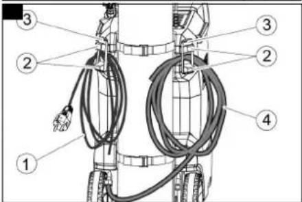
Illustration L
① Mains cable
②Hose/cable holder
③Rubber tensioner
④ Exhaust hose
-
Disconnect the compressed air hose from the device.
-
Wind up the exhaust hose, hang it on a hose/cable holder and secure it with the rubber tensioner.
- Wind up the abrasive hose and hang it on the abrasive hose holder.
- Insert the jet gun with the cone into the holder on the device.
Transport
△CAUTION
Risk of accidents and injuries
Take the weight of the device into account for transportation and storage. See chapter "Technical data".
ATTENTION
Risk of damage
Engine oil can escape when transporting horizontally. A subsequent lack of oil can lead to damage during the next operation. Transport the device only in a standing upright position.
- Carry out all the steps in the "Ending operation" chapter before transport.
- Release the parking brakes on the steering rollers and push the device by the push handle.
- Remove the carbon dioxide bottle from the device before loading it into a vehicle.
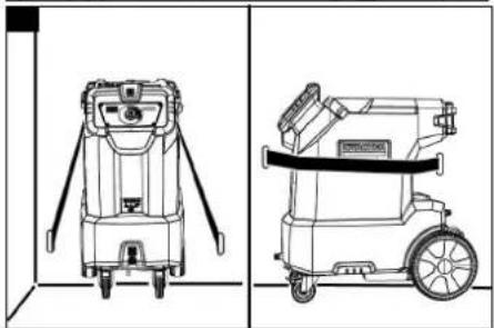
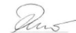
- The device can be lifted by 2 people. Each person uses a handle on the underside of the device and supports the device with the other hand on the upper edge.
- For transport in vehicles, lock the parking brakes on the steering rollers and secure the device with a tension belt. Illustration M
Storage
△CAUTION
Risk of accidents and injuries
Take the weight of the device into account for transportation and storage. See chapter "Technical data".
The device may only be stored indoors.
△DANGER
Risk of asphyxiation
Carbon dioxide can accumulate in enclosed spaces and cause death by asphyxiation.
Only store carbon dioxide bottles (even if they are connected to the device) in well-ventilated locations.
Care and service
Maintenance instructions
Regular maintenance according to the following maintenance plan is fundamental for a safely operating system.
Use only original manufacturer spare parts or parts recommended by the original manufacturer, such as
- Spare parts and wearing parts,
- Accessories,
- Operating materials,
- Detergent.
△DANGER
Danger of accident
The device can start unintentionally. Cold unit parts or liquid carbon dioxide can cause frostbite. Gaseous carbon dioxide can cause death by asphyxiation.
Before working on the device, carry out all the steps in the "Ending operation" chapter. Wait until the device has warmed up or wear cold protection clothing. Never put dry ice in your mouth.
ATTENTION
Risk of damage
Using the wrong detergent can damage the device and the jet gun.
Never clean the device or the jet gun with solvents, petrol or detergents containing oil.
Service contract
We recommend that you close a service contract to ensure reliable operation of the system. Please contact your KÄRCHER customer service department responsible.
Maintenance plan
Daily before the start of operations
- Carefully examine the abrasive hose for cracks, kink points and other damage. Soft spots in the hose indicate wear on the inside of the hose. Replace the defective or worn hose with a new hose.
- Examine electrical cables and plugs for damage. Have defective parts replaced by Customer Service.
Every 100 operating hours
- Check the couplings on the abrasive hose and on the device for damage and wear. Replace a defective hose, have defective couplings on the unit replaced by Customer Service.
Every 500 operating hours or annually
- Have the device checked by Customer Service.
Every 2 years
- Renew the abrasive hose at least every 2 years.
Tests
According to DGUV R 100-500, the following tests must be carried out on the unit by an expert. The results of the test must be recorded in a test certificate. The operator of the device must keep the test certificate until the next test.
After a business interruption of more than a year
- Check the device for correct condition and function.
After changing the installation site
- Check the device for proper condition, function and installation.
After repair work or changes that can affect operational safety
- Check the device for proper condition, function and installation.
Troubleshooting guide
△DANGER
Danger of accident
The device can start unintentionally. Cold device parts or liquid carbon dioxide can cause frostbite. Gaseous carbon dioxide can cause death by asphyxiation. Before working on the device, carry out all the steps in the "Ending operation" chapter. Wait until the device has warmed up or wear cold protection clothing. Never put dry ice in your mouth.
ATTENTION
Risk of damage
Using the wrong detergent can damage the device and the jet gun.
Never clean the device or the jet gun with solvents, petrol or detergents containing oil.
Fault display
Faults are indicated by the indicator lights on the control panel.
Illustration N
①Jet gun fault indicator
② Compressed air supply fault indicator
③Fault indication pellet generation
④ Fault indication pellet dosing
Troubleshooting
Malfunctions often have simple causes that you can remedy yourself using the following overview. When in doubt, or in the case of malfunctions not mentioned here, please contact your authorised Kärcher Customer Service.
| Fault Rectification | |
| The jet gun fault indicator lights up | ● Do not pull the trigger of the jet gun before switching it on. ● Remove the fastener on the trigger of the jet gun. |
| The jet gun fault indicator flashes | ● Check that the control cable of the jet gun is connected to the device. ● Check the control cable on the abrasive hose for damage. |
| The compressed air supply fault indicator lights up | ● Increase the air pressure. |
| The compressed air supply fault indicator flashes | ● Check the exhaust hose for clogging. ● The carbon dioxide bottle is too hot and therefore has too high a pressure. Set up the device including the carbon dioxide bottle in a cooler location or protect it from direct sunlight. |
| The pellet production fault indicator lights up | ● Allow the device to thaw out. Check the carbon dioxide filter and change it if necessary. Then perform a reset.● If the malfunction occurs repeatedly, replace the carbon dioxide bottle. |
| The pellet metering fault indicator lights up | ● Switch the device off and back on again.● If the fault indicator remains lit, contact the customer service. |
| The pellet metering fault indicator flashes | ● Allow the metering motor to cool down. Position the device so that air can flow into the device from below. Contact Customer Service if necessary. |
| The voltage supply indicator light does not light up | ● Plug the mains plug into the socket.● Check the on-site voltage supply. |
| The compressed air indicator light does not light up | ● Connect a compressed air hose to the device.● Open the stop valve in the on-site compressed air supply. |
| The device does not work | ● Check the indicator lights and fault indicators.● Perform a reset. |
| Poor cleaning performance | ● Turn the program switch to a higher level.● Increase the jet pressure.● Check the filling level of the carbon dioxide bottle.● Do not use a heated carbon dioxide bottle. Protect the carbon dioxide bottle from heat radiation. The effectiveness of the pellet production drops sharply if the temperature of the carbon dioxide is above 31 °C.● Allow the abrasive hose and the jet gun to thaw to clear any blockages. Then increase the jet pressure. |
| Pellet dosage too low | ● Turn the program switch to a higher level.● Replace the carbon dioxide filter between the carbon dioxide bottle and the device. |
| Recurring interruptions in the dry ice stream | ● Turn the programme switch to a lower level or increase the jet pressure.● If the jet nozzle is clogged:a Immediately close the carbon dioxide bottle.b Allow the unit to thaw for 30 minutes.c Increase the jet pressure.d Start the appliance with the carbon dioxide bottle closed to remove pellet residues. |
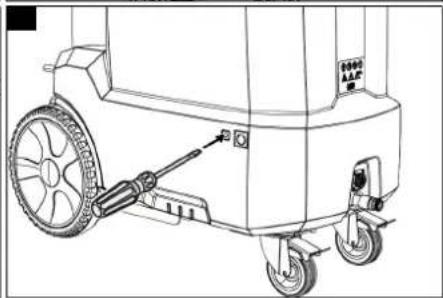
Performing a reset
- Press the reset button inside the device with a screwdriver.
Illustration O
Replacing the carbon dioxide filter
ATTENTION
Malfunctions
Contaminated carbon dioxide can cause malfunctions.
When working on the carbon dioxide filter, be careful not to get any dirt into the device.
ATTENTION
Malfunctions
Malfunctions due to contamination.
After each loosening or unscrewing of the screw plug, the carbon dioxide filter and the copper seal must be replaced. If this is not done, particles can become detached from the carbon dioxide filter and lead to malfunctions.
Note
The carbon dioxide filter is backwashed and cleaned as soon as the pressurised cylinder connection is disconnected from the carbon dioxide cylinder. Regular replacement of the carbon dioxide filter is therefore not necessary.
- Close the stop valve on the carbon dioxide bottle.
- Operate the unit at the highest level for about 1 minute to depressurise the carbon dioxide hose.
- Unscrew the screw flange on the carbon dioxide bottle.
- Carefully unscrew the screw plug from the screw flange. Let the hose flange
hang down to prevent dirt from entering the carbon dioxide hose.
Illustration P
①Screw flange
②Carbon dioxide filter
③Copper sealing ring
④Screw plug
- Remove the carbon dioxide filter.
- Vacuum out the screw plug and the screw flange.
- Carefully press the new carbon dioxide filter onto the screw plug by hand.
- Replace the copper seal.
- Tighten the screw plug, holding the wide hexagon of the screw flange with an open-end wrench.
Tightening torque: 80 Nm.
Warranty
The warranty conditions issued by our relevant sales company apply in all countries. We shall remedy possible malfunctions on your appliance within the warranty period free of cost, provided that a material or manufacturing defect is the cause. In a warranty case, please contact your dealer (with the purchase receipt) or the next authorised customer service site. (See overleaf for the address)
Accessories
ABS residual pressure valve
Order number 2.574-006.0
Necessary when using carbon dioxide bottles with a residual pressure valve.
Technical data
| IB 10/8 L2P | ||
| Electrical connection | ||
| Mains voltage V 220... | 230 | |
| Phase ~ 1 | ||
| Frequency | Hz | 50...60 |
| Power rating | kW | 1,0 |
| Degree of protection | IPX4 | |
| Leakage current, typical | mA <3,5 | |
| Residual current device | delta I, A | 0,03 |
Compressed air connection
| Compressed air hose,nominal width (min.) | Inches 0,5 | |
| Pressure (max.) | MPa(bar) | 1,0(10) |
| Compressed air consump-tion, max. | m3/min | 0,8 |
Device performance data
| Jet pressure, max. MPa | (bar) | 1,0(10) |
| Jet pressure, min. level 1 | MPa(bar) | 0,07(0,7) |
| Jet pressure, min. level 2 | MPa(bar) | 0,14(1,4) |
| Jet pressure, min. level 3 | MPa(bar) | 0,28(2,8) |
| Carbon dioxide consumption | kg/h | 20...60 |
| IB 10/8 L2P | |
| Recoil force of the jet gun, N max. | 40 |
| Carbon dioxide bottle | |
| Maximum filling quantity kg 37,5 | |
| Diameter, max. mm 220 | |
| Ambient conditions | |
| Air exchange m | ^3 /h 2000 |
| Dimensions and weights | |
| Typical operating weight (without carbon dioxide bottle) | kg 95 |
| Length mm 866 | |
| Width mm 443 | |
| Height without a carbon di- mm 970 oxide bottle | |
| Determined values in acc. with EN 60335-2-79 | |
| Hand-arm vibration value | m/s2 0,08 |
| Sound pressure level | dB(A) 95 |
| Sound power level LWA + K uncertaintyWA | dB(A) 115 |
| Subject to technical modifications. | |
Declaration of Conformity
EU Declaration of Conformity
We hereby declare that the machine described below complies with the relevant basic safety and health requirements in the EU Directives, both in its basic design and construction as well as in the version placed in circulation by us. This declaration is invalidated by any changes made to the machine that are not approved by us. Product: Ice Blaster
Type:
1.574-xxx (IB 10/8 L2P)
Currently applicable EU Directives
2006/42/EC (+2009/127/EC)
2014/30/EU
2011/65/EU
2009/125/EC + 2009/1781
Harmonised standards used
EN 60335-1
EN IEC 63000: 2018
EN 62233: 2008
EN 55014-1: 2017 + A11: 2020
EN 55014-2: 2015
EN 61000-3-2: 2014
EN 61000-3-3: 2013
The signatories act on behalf of and with the authority of the company management.
H. Jenner
Chairman of the Board of Management
S. Reiser
Director Regulatory Affairs & Certification
Documentation supervisor:
S. Reiser
Alfred Kärcher SE & Co. KG
Alfred-Kärcher-Str. 28 - 40
71364 Winnenden (Germany)
Ph.: +49 7195 14-0
Fax: +49 7195 14-2212
Winnenden, 2021/02/01
Declaration of Conformity (UK)
We hereby declare that the product described below complies with the relevant provisions of the following UK Regulations, both in its basic design and construction as well as in the version put into circulation by us. This declaration shall cease to be valid if the product is modified without our prior approval.
Product: Ice Blaster
Type:
1.574-xxx (IB 10/8 L2P)
Currently applicable UK Regulations
S.I. 2008/1597 (as amended)
S.I. 2016/1091 (as amended)
S.I. 2012/3032 (as amended)
2009/125/EC + 2009/1781
Designated standards used
EN 60335-1
EN IEC 63000: 2018
EN 62233: 2008
EN 55014-1: 2017 + A11: 2020
EN 55014-2: 2015
EN 61000-3-2: 2014
EN 61000-3-3: 2013
The signatories act on behalf of and with the authority of the company management.
H. Jenner
Chairman of the Board of Management
S. Reiser
Director Regulatory Affairs & Certification
Documentation supervisor:
S. Reiser
Alfred Kärcher SE & Co. KG
Alfred-Kärcher-Str. 28 - 40
71364 Winnenden (Germany)
Ph.: +49 7195 14-0
Fax: +49 7195 14-2212
Winnenden, 2021/02/01
Contenu
H. Jenner
Chairman of the Board of Management
S. Reiser
Director Regulatory Affairs & Certification
Responsable de la documentation : S. Reiser
Alfred Kärcher SE & Co. KG
Alfred-Kärcher-Str. 28 - 40
71364 Winnenden (Germany)
1.574-xxx (IB 10/8 L2P)
H. Jenner
Chairman of the Board of Management

S. Reiser
Director Regulatory Affairs & Certification
71364 Winnenden (Germany)
Tel.: +49 7195 14-0
Fax: +49 7195 14-2212
Winnenden, 01/02/2021
Inhoud
③Klantenservice is nodig
Product: Ice Blaster
Type:
1.574-xxx (IB 10/8 L2P)
H. Jenner
Chairman of the Board of Management
S. Reiser
Director Regulatory Affairs & Certification
71364 Winnenden (Germany)
Tel.: +49 7195 14-0
Fax: +49 7195 14-2212
Winnenden, 2021/02/01
1.574-xxx (IB 10/8 L2P)
Directivas UE aplicables
2006/42/CE (+2009/127/CE)
2014/30/UE
2011/65/UE
2009/125/CE + 2009/1781

Jenner
Chairman of the Board of Management
S. Reiser
Director Regulatory Affairs & Certification
71364 Winnenden (Germany)
Tel.: +49 7195 14-0
Fax: +49 7195 14-2212
Winnenden, 01/02/2021
Indice
1.574-xxx (IB 10/8 L2P)
2006/42/CE (+2009/127/CE)
2014/30/UE
2011/65/UE
2009/125/CE + 2009/1781
Winnenden, 01/02/2021
Indhold
1.574-xxx (IB 10/8 L2P)
2006/42/EF (+2009/127/EF)
2014/30/EU
2011/65/EU
2009/125/EF + 2009/1781

H. Jenner
Chairman of the Board of Management
S. Reiser
Director Regulatory Affairs & Certification
71364 Winnenden (Germany)
Tlf.: +49 7195 14-0
Fax: +49 7195 14-2212
Winnenden, 2021/02/01
Indhold
③3Holdeskinne for Homebase
Programbryter i trinn 1–3:
Figur B
①Stråletrykk
②Total driftstid
1.574-xxx (IB 10/8 L2P)
Gjeldende EU-direktiver
2006/42/EF (+2009/127/EF)
2014/30/EU
2011/65/EU
2009/125/EF + 2009/1781
Anvendte harmoniserte standarder
EN 60335-1
EN IEC 63000: 2018
EN 62233: 2008
EN 55014-1: 2017 + A11: 2020
EN 55014-2: 2015
EN 61000-3-2: 2014
EN 61000-3-3: 2013

Chairman of the Board of Management
S. Reiser
Director Regulatory Affairs & Certification
71364 Winnenden (Germany)
Tlf.: +49 7195 14-0
Winnenden, 2021/02/01
Innehåll
Allmän information.... 70
1.574-xxx (IB 10/8 L2P)
H. Jenner
Chairman of the Board of Management

S. Reiser
Director Regulatory Affairs & Certification
D-71364 Winnenden (Germany)
Tfn: +49 7195 14-0
Fax: +49 7195 14-2212
Winnenden, 2021-02-01
Sisältö
1.574-xxx (IB 10/8 L2P)
H. Jenner
Chairman of the Board of Management

S. Reiser
Director Regulatory Affairs & Certification
71364 Winnenden (Germany)
Puh.: +49 7195 14-0
1.574-xxx (IB 10/8 L2P)
Σχετικές Οδηγίες ΕΕ
2006/42/EK (+2009/127/EK)
2014/30/EE
2011/65/EE
2009/125/EK + 2009/1781

H. Jenner
Chairman of the Board of Management
S. Reiser
Director Regulatory Affairs & Certification
71364 Winnenden (Germany)
Tηλ.: +49 7195 14-0
Φαξ: +49 7195 14-2212
Winnenden, 2021/02/01
İçindekiler
Genel uyarılar 92
1.574-xxx (IB 10/8 L2P)
2006/42/AT (+2009/127/AT)
2014/30/AB
2011/65/AT
2009/125/EG + 2009/1781

H. Jenner
Chairman of the Board of Management
S. Reiser
Director Regulatory Affairs & Certification
Winnenden, 2021/02/01
Содержание
Общие указания 99
1.574-xxx (IB 10/8 L2P)
H. Jenner
Chairman of the Board of Management
S. Reiser
Director Regulatory Affairs & Certification
71364 Winnenden (Germany)
Тел.: +49 7195 14-0
Факс: +49 7195 14-2212
1.574-xxx (IB 10/8 L2P)
H. Jenner
Chairman of the Board of Management
S. Reiser
Director Regulatory Affairs & Certification
Winnenden, 2021/02/01
Obsah
www.kaercher.com/REACH
Bezpečnostní pokyny
1.574-xxx (IB 10/8 L2P)
2006/42/ES (+2009/127/ES)
2014/30/EU
2011/65/EU
2009/125/EG + 2009/1781

H. Jenner
Chairman of the Board of Management
S. Reiser
Director Regulatory Affairs & Certification
Winnenden, 2021/02/01
Kazalo
Splošna navodila 122
Namenska uporaba 122
Delovanje.... 122
Varovanje okolja.... 122
Varnostna navodila 122
Varnostne naprave.... 123
Pribor in nadomestni deli 124
Obseg dobave 124
Upravljalni elementi.... 124
Zagon.... 124
Upravljanje.... 125
Konec uporabe 126
Transport.... 126
1.574-xxx (IB 10/8 L2P)
Zadevne EU-direktive
2006/42/ES (+2009/127/ES)
2014/30/EU
2011/65/EU
2009/125/ES + 2009/1781
H. Jenner
Chairman of the Board of Management
S. Reiser
Director Regulatory Affairs & Certification
Winnenden, 1. 2. 2021
Spis treści
1.574-xxx (IB 10/8 L2P)
2006/42/WE (+2009/127/WE)
2014/30/UE
2011/65/UE
2009/125/WE + 2009/1781

H. Jenner
Chairman of the Board of Management
S. Reiser
Director Regulatory Affairs & Certification
71364 Winnenden (Germany)
Tel.: +49 7195 14-0
1.574-xxx (IB 10/8 L2P)
Directive UE relevante
2006/42/UE (+2009/127/UE)
2014/30/UE
2011/65/UE
2009/125/CE + 2009/1781
Norme armonizate aplicate
EN 60335-1
EN IEC 63000: 2018
EN 62233: 2008
EN 55014-1: 2017 + A11: 2020
EN 55014-2: 2015
EN 61000-3-2: 2014
EN 61000-3-3: 2013
H. Jenner
Chairman of the Board of Management
S. Reiser
Director Regulatory Affairs & Certification
71364 Winnenden (Germania)
Tel.: +49 7195 14-0
Fax: +49 7195 14-2212
Winnenden, 2021/02/01
Obsah
Všeobecné upozornenia.... 144
1.574-xxx (IB 10/8 L2P)
2006/42/ES (+2009/127/ES)
2014/30/EÚ
2011/65/EÚ
2009/125/ES + 2009/1781
H. Jenner
Chairman of the Board of Management
S. Reiser
Director Regulatory Affairs & Certification
71364 Winnenden (Germany)
Tel.: +49 7195 14-0
Fax: +49 7195 14-2212
Winnenden, 01.02.2021
Sadržaj
| Opće napomene | 151 |
| Namjenska uporaba | 151 |
| Funkcija | 151 |
| Zaštita okoliša | 152 |
| Sigurnosni napuci | 152 |
| Sigurnosni uređaji | 153 |
| Pribor i zamjenski dijelovi | 153 |
| Sadržaj isporuke | 153 |
| Upravljački elementi | 153 |
| Puštanje u pogon | 153 |
| Rukovanje | 155 |
| Završetak rada | 156 |
| Transport | 156 |
| Skladištenje | 156 |
| Njega i održavanje | 156 |
| Pomoć u slučaju smetnji | 157 |
| Jamstvo | 158 |
| Pribor | 158 |
| Tehnički podaci | 158 |
| EU izjava o sukladnosti | 158 |
Opće napomene
Prije prve uporabe uređaja pročitajte ove originalne upute za rad i postupajte u skladu s njima. Čuvajte originalne upute za rad za kasniju uporabu ili za sljedećeg vlasnika.
Namjenska uporaba
1.574-xxx (IB 10/8 L2P)
2006/42/EZ (+2009/127/EZ)
2014/30/EU
2011/65/EU
2009/125/EZ + 2009/1781
H. Jenner
Chairman of the Board of Management
S. Reiser
Director Regulatory Affairs & Certification
Opunomoćenik za dokumentaciju:
S. Reiser
Alfred Kärcher SE & Co. KG
Alfred-Kärcher-Str. 28 - 40
71364 Winnenden (Njemačka)
Tel.: +49 7195 14-0
Telefaks: +49 7195 14-2212
Winnenden, 01.02.2021.
Sadržaj
Opšte napomene 158
Namenska upotreba.... 158
Funkcija.... 159
Zaštita životne sredine.... 159
Sigurnosne napomene.... 159
Sigurnosni uređaji 160
Pribor i rezervni delovi 160
Obim isporuke.... 160
Komandni elementi 160
Puštanje u pogon.... 161
Rukovanje 162
Završetak rada.... 163
Transport.... 163
1.574-xxx (IB 10/8 L2P)
Važeće direktive EU
2006/42/EZ (+2009/127/EZ)
2014/30/EU
2011/65/EU
2009/125/EZ + 2009/1781
Primenjene harmonizovane norme
EN 60335-1
EN IEC 63000: 2018
EN 62233: 2008
EN 55014-1: 2017 + A11: 2020
EN 55014-2: 2015
EN 61000-3-2: 2014
EN 61000-3-3: 2013
Potpisnici deluju po nalogu i uz punomoć upravnog odbora.

H. Jenner
Chairman of the Board of Management
S. Reiser
Director Regulatory Affairs & Certification
Lice ovlašćeno za dokumentaciju:
S. Reiser
Alfred Kärcher SE & Co. KG
Alfred-Kärcher-Str. 28 - 40
71364 Winnenden (Germany)
Tel.: +49 7195 14-0
Winnenden, 2021/02/01
Съдържание
Общи указания 165
Употреба по предназначение ..... 166
Функция.... 166
1.574-xxx (IB 10/8 L2P)

H. Jenner
Chairman of the Board of Management
S. Reiser
Director Regulatory Affairs & Certification
71364 Winnenden (Germany)
Тел.: +49 7195 14-0
Факс: +49 7195 14-2212
Виненден, 2021/02/01
Sisukord
Üldised juhised 174
1.574-xxx (IB 10/8 L2P)
2006/42/EÜ (+2009/127/EÜ)
2014/30/EL
2011/65/EL
2009/125/EÜ + 2009/1781
H. Jenner
Chairman of the Board of Management
S. Reiser
Director Regulatory Affairs & Certification
71364 Winnenden (Germany)
Tel: +49 7195 14-0
Winnenden, 2021/02/01
Saturs
1.574-xxx (IB 10/8 L2P)
H. Jenner
Chairman of the Board of Management
S. Reiser
Director Regulatory Affairs & Certification
Pilnvarotais sagatavot dokumentāciju: S. Reizers (S. Reiser)
Alfred Kärcher SE & Co. KG
Alfred-Kärcher-Str. 28 - 40
1.574-xxx (IB 10/8 L2P)
Atitinkamos ES direktyvos
2006/42/EB (+2009/127/EB)
2014/30/ES
2011/65/ES
2009/125/EG + 2009/1781
Taikomi darnieji standartai
EN 60335-1
EN IEC 63000: 2018
EN 62233: 2008
EN 55014-1: 2017 + A11: 2020
EN 55014-2: 2015
EN 61000-3-2: 2014
EN 61000-3-3: 2013
H. Jenner
Chairman of the Board of Management
S. Reiser
Director Regulatory Affairs & Certification
71364 Winnenden (Germany)
Тел.: +49 7195 14-0
Факс: +49 7195 14-2212
Portuguese Portuguese Portuguese Portuguese Portuguese Portuguese Portuguese Portuguese Portuguese Portuguese Portuguese Portuguese Portuguese Portuguese Portuguese Portuguese Portuguese Portuguese Portuguese Portuguese Portuguese Portuguese Portuguese Portuguese Portuguese Portuguese Portuguese Portuguese Portuguese Portuguese Portuguese Portuguese Portuguese Portuguese Portuguese Portuguese Portuguese Portuguese Portuguese Portuguese Portuguese Portuguese Portuguese Portuguese Portuguese Portuguese Portuguese Portuguese Portuguese Portuguese Portuguese
natural_image
Black silhouette of a hand giving a thumbs-up gesture (no text or symbols)THANK YOU!
MERCI! DANKE! iGRACIAS!

Register your product and benefit from many advantages.
www.kaercher.com/welcome


Rate your product and tell us your opinion.
natural_image
Icon showing a gear and wrench inside a square frame (no text or symbols)www.kaercher.com/dealersearch
Alfred Kärcher SE & Co. KG
Alfred-Kärcher-Str. 28-40
71364 Winnenden (Germany)
Tel.: +49 7195 14-0
Fax: +49 7195 14-2212