IB 740 Classic - Steam cleaner Kärcher - Free user manual and instructions
Find the device manual for free IB 740 Classic Kärcher in PDF.
User questions about IB 740 Classic Kärcher
0 question about this device. Answer the ones you know or ask your own.
Ask a new question about this device
Download the instructions for your Steam cleaner in PDF format for free! Find your manual IB 740 Classic - Kärcher and take your electronic device back in hand. On this page are published all the documents necessary for the use of your device. IB 740 Classic by Kärcher.
USER MANUAL IB 740 Classic Kärcher
natural_image
Professional KARCHER Gas 7/40 industrial pressure testing machine with visible hoses and control panel (no text or symbols on device body)Deutsch 3
English 13
Français 23
Italiano 34
Nederlands 45
Español 55
Português 66
Dansk 77
Norsk 87
Svenska 97
Suomi 107
Ελληνικά 117
Türkçe 128
Русский 138
Magyar 149
Čeština 159
Slovenščina 169
Polski 179
Românește 190
Slovenčina 201
Hrvatski 211
Srpski 221
Български 231
Eesti 242
Latviešu 252
Lietuviškai 262
Українська 272
中文 283
العربية 305
⚠Gefahr
natural_image
Line drawing of a cylindrical mechanical component with flanged ends (no text or symbols)Handgriff (Zubehör)
natural_image
Line drawing of a mechanical bolt with a flanged cap (no text or symbols)natural_image
Technical line drawing of a mechanical pulley or wheel assembly (no text or symbols)line
| A | B | C | |---|---|---| | 0.2 | 2 | 85 | | 0.4 | 4 | 87 | | 0.6 | 6 | 90 | | 0.8 | 8 | 93 | | 1.0 | 10 | 95 | The chart displays a single line representing category '1' through category '5'. The x-axis is labeled 'A' and the y-axis is labeled 'B'. The lines are connected by solid, dashed, dotted, and dash-dot styles to the same y-axis label. No explicit numerical values or units are provided for the series.line
| X-Axis | Series 1 | Series 2 | Series 3 | Series 4 | Series 5 | |---|---|---|---|---|---| | 0.2 | 93 | 94 | 96 | 98 | 97 | | 0.4 | 95 | 97 | 100 | 102 | 98 | | 0.6 | 97 | 100 | 103 | 105 | 100 | | 0.8 | 99 | 103 | 106 | 108 | 102 | | 1.0 | 101 | 106 | 109 | 111 | 105 | The chart displays a single data series with x-axis labeled 'A' (ranging from 0.2 to 1.0) and y-axis labeled 'C' (ranging from 93 to 115). The series are represented by different line styles, each corresponding to a distinct series labeled 1 through 5 in the legend. No trend or correlation is present — this is a static categorical comparison.
Chairman of the Board of Management

Director Regulatory Affairs & Certification
71364 Winnenden (Germany)
Tel.: +49 7195 14-0
Fax: +49 7195 14-2212
Winnenden, 2021/02/01
Please read and comply with these original instructions prior to the initial operation of your appliance and store them for later use or subsequent owners.
Contents
Environmental protection .. EN .. 1
Safety instructions ..... EN .. 1
Proper use ..... EN .. 2
Function ..... EN .. 2
Control elements..... EN .. 2
Start up.... EN .. 3
Operation ..... EN .. 4
Shutting down..... EN .. 6
Transport..... EN .. 6
Storage ..... EN .. 6
Maintenance and care .... EN .. 6
Troubleshooting ..... EN .. 7
Technical specifications ... EN .. 9
Accessories ..... EN . 10
Warranty ..... EN . 10
EU Declaration of Conformity EN . 10
Declaration of Conformity .. EN . 10
Environmental protection
| The packaging material can be recycled. Please do not place the packaging into the ordinary refuse for disposal, but arrange for the proper recycling. | |
| Old appliances contain valuable materials that can be recycled. Please arrange for the proper recycling of old appliances. Batteries, oil, and similar substances must not enter the environment. Please dispose of your old appliances using appropriate collection systems. |
Notes about the ingredients (REACH)
You will find current information about the ingredients at:
www.kaercher.com/REACH
Safety instructions
The appliance may only be operated by persons who have read and understood the contents of this operating instructions manual. Please ensure that you conform to all the safety instructions and regulations.
→ This operating instructions manual must be stored in such a way that it can be easily accessed by the operator.
Danger or hazard levels
⚠️Danger
Immediate danger that can cause severe injury or even death.
⚠ Warning
Possible hazardous situation that could lead to severe injury or even death.
Caution
Possible hazardous situation that could lead to mild injury to persons or damage to property.
Symbols on the machine
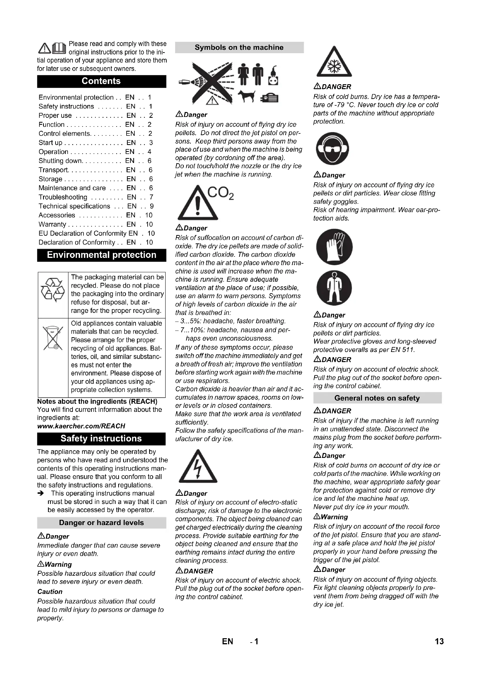
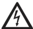
⚠️Danger
Risk of injury on account of flying dry ice pellets. Do not direct the jet pistol on persons. Keep third persons away from the place of use and when the machine is being operated (by cording off the area). Do not touch/hold the nozzle or the dry ice jet when the machine is running.
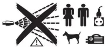
⚠️Danger
Risk of suffocation on account of carbon dioxide. The dry ice pellets are made of solidified carbon dioxide. The carbon dioxide content in the air at the place where the machine is used will increase when the machine is running. Ensure adequate ventilation at the place of use; if possible, use an alarm to warn persons. Symptoms of high levels of carbon dioxide in the air that is breathed in:
- 3...5%: headache, faster breathing.
- 7...10%: headache, nausea and perhaps even unconsciousness.
If any of these symptoms occur, please switch off the machine immediately and get a breath of fresh air; improve the ventilation before starting work again with the machine or use respirators.
Carbon dioxide is heavier than air and it accumulates in narrow spaces, rooms on lower levels or in closed containers.
Make sure that the work area is ventilated sufficiently.
Follow the safety specifications of the manufacturer of dry ice.
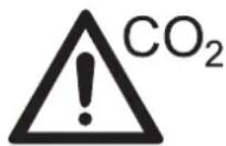
⚠Danger
Risk of injury on account of electro-static discharge; risk of damage to the electronic components. The object being cleaned can get charged electrically during the cleaning process. Provide suitable earthing for the object being cleaned and ensure that the earthing remains intact during the entire cleaning process.
⚠️DANGER
Risk of injury on account of electric shock. Pull the plug out of the socket before opening the control cabinet.
DANGER
Risk of cold burns. Dry ice has a temperature of -79 °C. Never touch dry ice or cold parts of the machine without appropriate protection.

⚠️Danger
Risk of injury on account of flying dry ice pellets or dirt particles. Wear close fitting safety goggles.
Risk of hearing impairment. Wear ear-protection aids.


⚠️Danger
Risk of injury on account of flying dry ice pellets or dirt particles.
Wear protective gloves and long-sleeved protective overalls as per EN 511.
DANGER
Risk of injury on account of electric shock. Pull the plug out of the socket before opening the control cabinet.
General notes on safety
⚠️DANGER
Risk of injury if the machine is left running in an unattended state. Disconnect the mains plug from the socket before performing any work.
⚠️Danger
Risk of cold burns on account of dry ice or cold parts of the machine. While working on the machine, wear appropriate safety gear for protection against cold or remove dry ice and let the machine heat up. Never put dry ice in your mouth.
⚠ Warning
Risk of injury on account of the recoil force of the jet pistol. Ensure that you are standing at a safe place and hold the jet pistol properly in your hand before pressing the trigger of the jet pistol.
⚠️Danger
Risk of injury on account of flying objects. Fix light cleaning objects properly to prevent them from being dragged off with the dry ice jet.
⚠ Warning
Do not use the appliance when there are other persons around unless they are also wearing safety equipment.
The appliance must not be used if a connecting line or important parts of the appliance, e.g. safety devices, spray hose, spray gun.
Danger of crushing on account of the dosing equipment. Always remove the machine plug from the socket before removing the protective shield of the dry ice container.
Specifications and Guidelines
For the operation of this system the following regulations and directives are applicable in the Federal Republic of Germany (available from Carl Heymanns Verlag KG, Luxemburger Straße 449, 50939 Cologne):
- BGV D 26 Spray jet tasks
- Executing instructions for BGV D 26
– BGR 117 Working in closed rooms - BGR 189 Using safety gear
– BGR 195 Using of safety gloves - BGR 500 Working with spraying devices
– BGI 534 Working in closed rooms - BGI 836 Gas warner
Safety Devices
Emergency-stop button
If the emergency stop button is pressed, the dry ice dosing is stopped and the air flow from the nozzle is interrupted.
Switch-off in case of emergency
→ Release the trigger of the jet pistol.
→ Press emergency-stop button.
The dry ice dosing is stopped and the air flow from the nozzle is interrupted.
→ Interrupt the compressed air supply.
Proper use
The machine is used to remove dirt using dry ice pellets that are speeded up using an air jet.
The machine should not be operated in explosive environments.
Use only dry ice pellets as jet medium. Using any other jet medium can cause damage to the machine.
Function
The air pressure reaches the jet pistol via a pressure regulation valve. The valve opens when the trigger of the jet pistol is pressed and the air flow comes out from the jet pistol. Additionally, dry ice pellets are dosaged into the air stream via the dosing device.
With the version "IB 7/40 Advanced" the additional dosing can be switched off at the jet pistol. The dry ice pellets hit the surface to be cleaned and remove the dirt. Additional heat currents are formed between the dirt and the object to be cleaned by the -79 °C cold dry ice pellets; this results in the dirt being loosened. At the same time, dry ice immediately gets coverted into gaseous carbon dioxide on contact and requires 700 times the volume of dry ice. Thus, the dirt penetrated by the dry ice thus gets thrown off.
During the spraying operation through the jet, a vibrator located on the dry ice container ensures continuous sliding of the dry ice pellets.
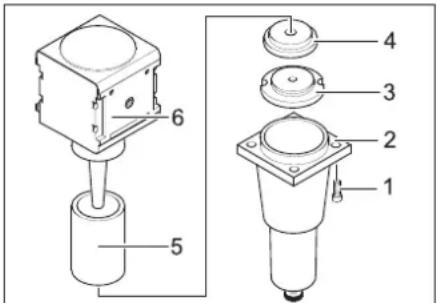
Control elements
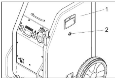
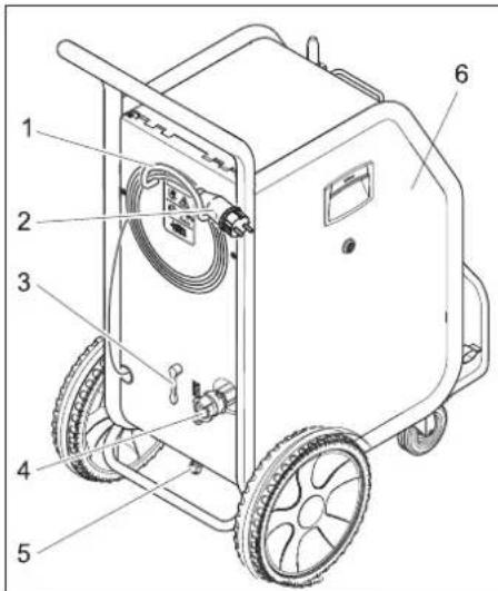
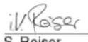
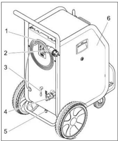
Device
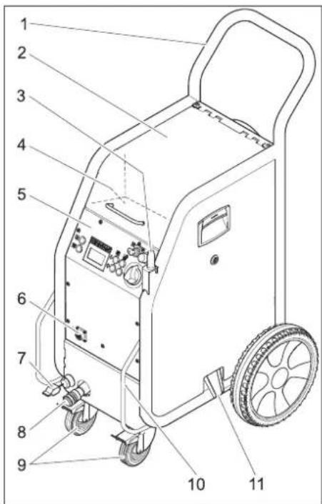
1 Push handle
2 Cover of the dry ice container
3 Holder for jet pistol
4 Storage compartment for accessories
5 Operating field
6 Coupling of the control cable
7 Earthing rope with clamp (only IB 7/40 Advanced, option for IB 7/40 Classic)
8 Coupling spray agent hose
9 Guiding roll with fixed position brake
10 Transport handle, bumper at the rear
11 Dry ice outlet for emptying the container
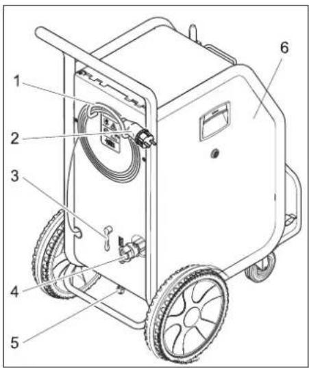
1 Cable clamp
2 Mains cable with mains plug
3 Pressure relief valve, condensate draining of the water separator
4 Compressed air connection
5 Condensate drain-out
6 Fuse F1, below the side panel
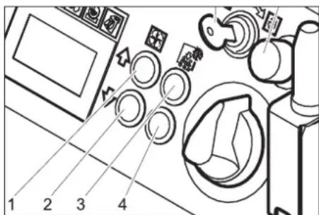
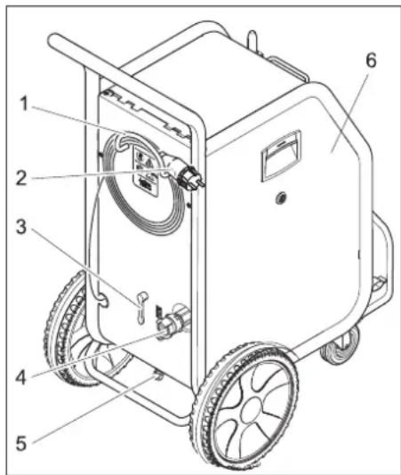
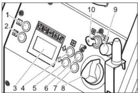
Operating field
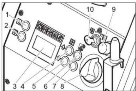
1 Statistics key, reset counter
2 Key to empty the dry ice container
3 Display
4 Key "increase jet pressure"
5 Key "decrease jet pressure"
6 Increase the dry ice dosing
7 Decrease the dry ice dosing
8 Power switch
9 Emergency-stop button
10 Key switch
Display
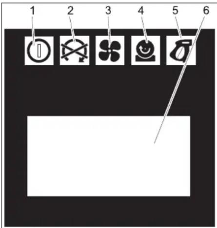
1 Indicator lamp - control voltage
green: Control voltage OK
red: Control voltage too low
yellow: Emptying of dry ice container active
2 Indicator lamp emergency STOP
red: Emergency stop button activated
green: Emergency stop button not activated
3 Indicator lamp - compressed air
green: Pressure OK
orange: selected jet pressure not reached
red: Pressure too low (below 0.15 MPa/1.5 bar)
4 Indicator lamp – dosing device
green: Drive OK
red: Error in drive
5 Indicator lamp - jet pistol
green: Jet pistol OK
orange: The trigger of the jet pistol was activated during the switch-on process
red: Jet pistol disconnected or control line damaged
6 Display field
Jet equipment
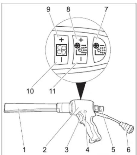
1 Nozzle
2 Jet pistol
3 Trigger
4 Safety button
5 Coupling spray agent hose
6 Coupling of the control cable
Only with IB 7/40 Advanced:
7 Key for the dry ice dosing on/off
Illuminates red when the dry ice dosaging is switched off
8 Increase the dry ice dosing
9 Key "increase jet pressure"
10 Key "decrease jet pressure"
11 Decrease the dry ice dosing
Start up
⚠️Danger
Risk of injury on account of flying dry ice pellets.
While preparing the appliance, check and ensure that all components, especially the spray agent hose are in proper condition. Replace damaged components with defect-free ones.
Clean dirty components and ensure that they are in proper working condition.
→ Place the machine on a horizontal, even surface and block the parking brakes of the steering rollers.
→ Connect the spray agent hose to the machine and secure it.
→ Connect the jet pistol to the spray agent hose and secure it.
→ Connect the control cable to the appliance.
→ Connect the control cable to the appliance.
Nozzles
Note
The choice of the nozzle depends on the material of the object to be cleaned and the contamination.
All nozzles can be screwed on top of the threading of the jet pistol without using any tools. The threaded surfaces on the nozzle are to be used to loosen tight nozzles using a spanner.
⚠️Danger
Risk of injury by the unit starting unintentionally. Switch off the unit before switching the nozzles.
⚠ Warning
Risk of injury by touching the cold nozzle. Warm up the nozzle before touching it or wear protective gloves.
Caution
Risk of cold welding Smear the enclosed grease on the nozzle threading before installing it.
Stream jets
1 Round jet nozzle, short
2 Round jet nozzle, long
3 Flat stream nozzle, short
4 Flat stream nozzle, long, included in delivery
5 Round stream nozzle, angled, with rubber coat
6 Flat stream nozzle, angled, with rubber coat
→ Place the nozzle onto the threaded suit port of the jet pistol and tighten it by hand.
Scrambler (accessory)
The scrambler crushes the dry ice pellets and is mounted between the jet pistol and the nozzle.
The alignment of the 4 holes plates in the scrambler indicates the degree of comminution.
Select the degree of comminution:
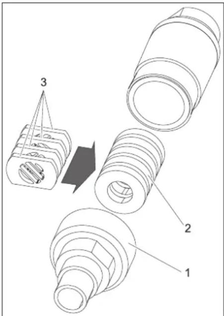
1 Screw connections
2 Magazine
3 Hole plate
→ Remove the screw connection.
→ Remove the magazine with hole plates.
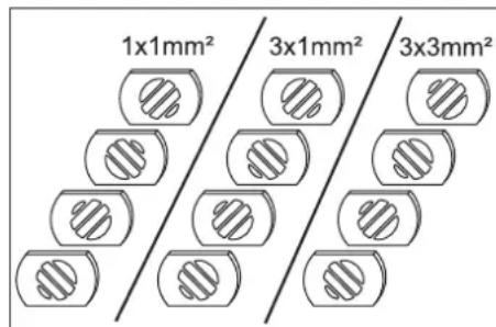
→ Align the hole plates, as shown above, in the magazine (3 possibilities). The above specifications in the illustration refer to the size of the permeation openings.
→ Insert the magazine with hole plates into the scrambler.
→ Unscrew the screw connection and tighten it.
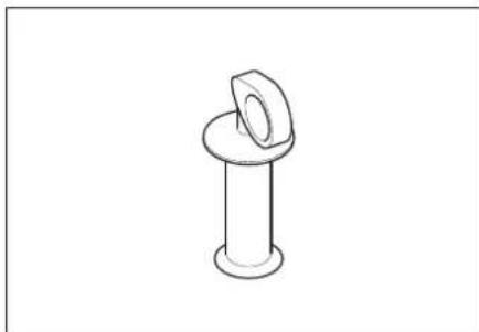
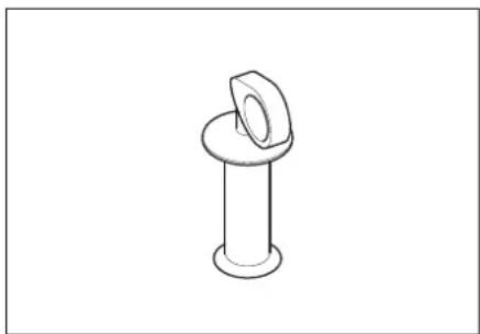
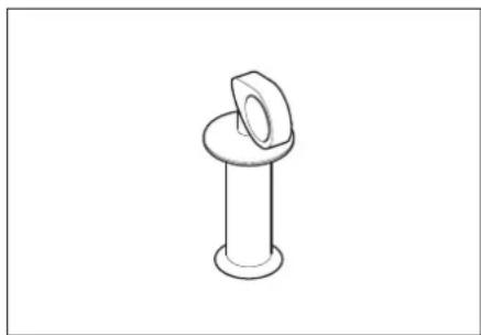
Nozzle extension (accessory)
An extension piece can be inserted between the jet pistol and the nozzle.
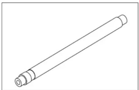
natural_image
Line drawing of a cylindrical mechanical component with flanged ends (no text or symbols)Handle (accessory)
The handle can be fastened on the extension piece.
natural_image
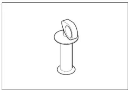
Simple line drawing of a bolt and nut (no text or symbols)Working light (accessory)
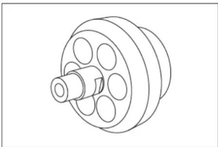
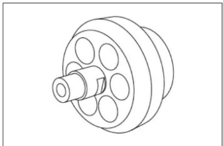
natural_image
Technical line drawing of a mechanical component with a central shaft and multiple circular holes (no text or symbols)The working light is connected between the jet pistol and the nozzle. Switching on and switching off is described in the chapter "Operation/Basic Settings".
Connect compressed air supply
Note
To ensure smooth functioning of the machine, the compressed air must have a low moisture content (max. 5% relative humidity, dewing point below 0^ C). The compressed air must also be free from oil, dirt and foreign particles.
The compressed air must be dry and oil-free, at least one aftercooler and a separator must be downstream of the compressor.
→ Close pressure relief valve.
→ Connect the compressed air inlet pipe to the compressed air connection point of the device.
The maximum permissible supply pressure of 1 MPa (10 bar) must not be exceeded.
Establish mains contact
⚠️Danger
Risk of electric shock.
The socket to be used must have been installed by an electrician and be compliant with IEC 60364-1.
The appliance may only be connected to a electricity source with proper earthing.
The socket used must be accessible and at a height between 0.6 m and 1.9 m off the floor.
The socket used must be in the viewing area of the operator.
The machine must have an FI fuse of type B, 30 mA.
Check the mains cables of the machine each time before using the machine to see that it is not damaged. Never operate a ma-
chine with damaged cables. Get the damaged cables replaced by an electrician. The extension cord must be protected by IPX4 safety mechanism and the cables must at least be compliant with H 07 RN-F 3G1.5.
→ Insert the mains plug into the socket.
Operation
Filling dry ice
⚠️Danger
Risk of cold burns. Dry ice has a temperature of -79 °C. Never touch dry ice or cold parts of the machine without appropriate protection. Wear protective gloves and protective overalls.
→ Open the cover of the dry ice containe
→ Check the dry ice container for presence of foreign particles and condensate, remove them if found.
→ Fill dry ice pellets into the container.
Caution
Risk of damage to the device. Use only dry ice pellets as jet medium. The use of any other spray agent will lead to loss of warranty coverage.
→ Close the cover of the dry ice containe
Note
To avoid disruptions in operations on account of melted dry ice pellets, it would make sense to fully use up the contents of the dry ice container before adding fresh dry ice. If the machine is to remain idle for a longer time, operate the device until the dry ice container is empty or empty the container via the dry ice emptying function.
Settings
Note
The settings depend on the substances contained in the detergent and the type of dirt.
→ Release emergency-stop button by turning.
→ Set the appliance switch to "I".
→ Turn the keyswitch in a clockwise direction.
→ Increase/reduce the jet pressure by using the respective keys.
Note
The higher you set the jet pressure, so much greater (more agressive) will the cleaning effect be.
→ Increase/reduce the dry ice dosing by using the respective keys.
→ Turn the keyswitch counter-clockwise and remove the key.
The automatic closure of the key hole will prevent contamination during operation.
When the key is removed, the device is protected against changes to the settings and resetting the statistics values.
Operation
→ Carry out maintenance jobs "daily before starting work" (see section "Maintenance and Care").
⚠️Danger
Risk of injury on account of flying dry ice pellets. Do not direct the jet pistol on persons. Keep third persons away from the place of use and when the machine is being operated (by cording off the area). Do not touch/hold the nozzle opening or the dry ice jet when the machine is running. First stop the compressed air supply before disconnecting the jet gun from the spray agent hose and the spray agent hose from the device; remove all pressure from the system and then pull the plug out of the socket.
→ Cordon off the working area to prevent persons coming close to the machine when it is being operated.
⚠️Danger
Risk of suffocation on account of carbon dioxide. The dry ice pellets are made of solidified carbon dioxide. The carbon dioxide content in the air at the place where the machine is used will increase when the machine is running. Ensure adequate ventilation at the place of use; if possible, use an alarm to warn persons. Symptoms of high levels of carbon dioxide in the air that is breathed in:
- 3...5%: headache, faster breathing.
- 7...10%: headache, nausea and perhaps even unconsciousness.
If any of these symptoms occur, please switch off the machine immediately and get a breath of fresh air; improve the ventilation before starting work again with the machine or use respirators.
Follow the safety specifications of the manufacturer of dry ice.
⚠️Danger
There is a danger because of dangerous to your health materials. If dust that is dangerous to your health can be generated, the appropriate safety measures will have to be taken prior to beginning work.
⚠️Danger
Risk of explosion!
Do not work on light metals and iron-containing substances simultaneously. If you alternate between working on light metals and iron-containing parts, the work area and the suction device must be cleaned between work cycles.
→ Ensure adequate ventilation while working in closed rooms in order to keep the carbon dioxide concentration in the atmospheric air in the room below the danger level.
→ Attach the object to be cleaned if necessary.
⚠️Danger
Risk of injury on account of electro-static discharge; risk of damage to the electronic components. The object being cleaned can get charged electrically during the cleaning process. Provide suitable earthing for the object being cleaned and ensure that the earthing remains intact during the entire cleaning process.
⚠ Warning
Risk of damage by foreign objects falling into the dry ice container. Keep cover of the dry ice container closed during operation.
→ Connect the grounding rope (with IB 7/40 Advanced only) electrically conductive with the cleaning object or ground the cleaning object in a different way.
→ Wear safety gear, safety gloves, close fitting safety goggles and ear-protection.
→ Switch on the compressed air supply.
→ Release emergency-stop button by turning.
→ Choose a safe place to stand, assume a secure body stance to avoid being thrown off-balance by the recoil pressure of the jet pistol.
In order to prevent the sudden recoil, a gradual increase of the jet pressure can be set up (see "Operation/Basic Setting", menu item "soft start").
→ Press in the safety knob of the jet pistol.
→ Activate the dry ice jet by pressing the trigger of the jet pistol and carry out the cleaning operation.
Note
With model IB 7/40 Advanced, the dosing of dry ice pellets can be switched on or off via the key dry ice dosing on/off on the jet pistol. When the dosing is turned off, the key illuminates red, the display shows "ice off".
In addition, with the IB 7/40 Advanced model, the jet pressure and the dry ice volume can be changed on the jet pistol.
⚠ Warning
Risk of damage to the dosing equipment on account of dirt. Keep the lid of the dry ice container closed during the spraying operation to prevent sprayed off dirt from entering it.
Switch-off in case of emergency
→ Release the trigger of the jet pistol.
→ Press emergency-stop button.
The dry ice dosing is topped and the air flow from the nozzle is interrupted.
→ Interrupt the compressed air supply.
Switching on after emergency-stop
→ Release emergency-stop button by turning.
Interrupting operation
→ Release the trigger of the jet pistol.
→ During breaks in operation, you can insert the jet pistol on the holder on the machine.
Note
During longer breaks in operations, the dry ice pellets can melt in the dry ice container. As far as possible, do not interrupt operations for more than 20 minutes. In case of extended interruptions, switch off the engine.
Drain off the condensate.
A water separator cleans the compressed air flowing to the device. This collects condensate in the water separator, that needs to be drained once in a while.
→ Place the collection trough under the condensate drain screw.
→ Open the pressure relief valve slowly and wait until the condensate has been drained from the device.
Note
Please dispose of condensate in an environmentally friendly manner.
Statistics functions
Retrieving values
→ Set the appliance switch to "I".
→ Press the Statistics key briefly to display the operating duration.
t: Operation duration since the last reset.
T: Total operating duration.
→ Press the Statistics key briefly to display the processed dry ice amount.
m: Dry ice volume since the last reset.
M: Total dry ice volume.
→ Press the Statistics key briefly to display the average dry ice consumption. q: Average dry ice consumption since the last reset.
Q: Average total dry ice consumption.
Reset values
→ Turn the keyswitch in a clockwise direction.
→ Press the statistics key for 4 seconds.
Note
The total values cannot be erased.
Basic settings
→ Press the keys to increase and decrease the jet pressure at the same time and hold them, turn the keyswitch clockwise.
In the operating mode basic settings, the keys have the following functions:
1 Increase value
2 Decrease value
3 Menu point to the top
4 Menu point to the bottom
| Menue point | Setting range | Description |
| Soft start | 0, 1, 2, 3, 4, 5 seconds | Soft start, duration until the selected jet pressure is reached |
| T_Dump | 1, 2, 3, 4, 5 minutes | Duration of the dry ice emptying process |
| Language | metric, imperial | Measurement units metric: kg/h, MPa imperial: lbs, psi |
| Beleuchtung | ON/OFF Switch the nozzle lighting (option) on/off | |
| Demo mode | ON/OFF Demo mode: The operation is simulated, compressed air and dry ice dispensing is locked. | |
Finish the basic settings
→ Turn the keyswitch counter-clockwise.
Shutting down
⚠️Danger
Risk of cold burns. Dry ice has a temperature of -79 °C. Never touch dry ice or cold parts of the machine without appropriate protection. Wear protective gloves and protective overalls.
⚠️Danger
Risk of injury on account of flying dry ice pellets. Do not direct the jet pistol on persons. Keep third persons away from the place of use and when the machine is being operated (by cording off the area).
→ Close the compressed air supply.
→ Place the collection trough under the condensate drain screw.
→ Open the pressure relief valve slowly and wait until the condensate and the compressed air have been drained from the device.
→ Place the collection trough under the dry ice exit.
→ Press the key to empty the dry ice and wait until the dry ice container is empty. The dry ice emptying stops after the preset time has elapsed (see "Basic Settings").
If needed, press the key to empty the dry ice container several times.
Note
Please dispose of condensate in an environmentally friendly manner.
→ Set the appliance switch to "0/OFF".
→ Disconnect the machine from the compressed air inlet.
→ Disconnect the main plug from the socket.
→ Clean and roll up the grounding rope.
Transport
⚠ Danger
Risk of accident on account of dry ice residue in the device. Remove all traces of dry ice before transporting the device in closed vehicle; otherwise there is a risk of carbon dioxide suffocation to the co-passengers.
Caution
Risk of injury and damage! Observe the weight of the appliance when you transport it.
→ Carry out all the steps listed in the chapter "Shut down" before transporting the device.
→ Mount the appliance on the transport vehicle.
→ Lock the breaks of the steering rollers.
→ Fasten the device to the vehicle using fastening belts.
Storage
Caution
Risk of injury and damage! Note the weight of the appliance in case of storage. This appliance must only be stored in interior rooms.
⚠Danger
Risk of suffocation due to accumulation of carbon dioxide. Store dry ice pellets only in areas that are well ventilated.
Maintenance and care
Maintenance instructions
The bases of a safe operating of the equipment is the regularly maintenance according to the following maintenance plan. Use exclusively original parts of the manufacturer or those parts recommended by him like
- parts and wearing parts,
– accessories parts,
– operating materials, - cleaning agents.
⚠️DANGER
Risk of accident while working on the appliance. Carry out all the steps described in the chapter "Shut down" before starting anhy work on the device.
⚠️Danger
Risk of cold burns on account of dry ice or cold parts of the machine. While working on the machine, wear appropriate safety gear for protection against cold or remove dry ice and let the machine heat up. Never put dry ice in your mouth.
⚠ Warning
Risk of damage. Do not use solvents, petrol or oil-based cleaners to clean the jet pistol.
Maintenance contract
In order to guarantee a reliable operation of the equipment, we success, you signed a maintenance agreement. Please refer to your local Kärcher service department.
Maintenance schedule
Daily before starting operations
→ Check the spray agent hose for damages, bends and other damages. Soft areas in the hose indicate wear on the inner side of the hose. Replace the defective or worn out hose with a new hose.
→ Check electrical cable and plug for damages. Get defective parts replaced by Customer Service.
Every 100 operating hours
→ Check couplings of the spray agent hose, on the device, at the jet pistol for damages or wear and tear. Get Customer Service to replace the defective hose, defective couplings on the device or jet pistol.
→ Check dosing equipment for damages or leaks. If you find any damages/leaks, inform Customer Service.
→ Check the attachment caps of the rear wheels for proper seating.
Every 500 hours or once a year
→ Get the device checked by Customer Service.
Every 2 years
→ Replace the spray agent hose at least once in 2 years.
Opening the device
The side panels of the device must be removed to access the device for maintenance jobs:
1 Side panels
2 Snap closure
→ Turn the snap closure counter-clock-wise.
→ Remove side panel.
Maintenance Works
Replace the filter insert in the water separator.

1 Screw
2 Lower part
3 Nut
4 Disc
5 Filter inlay
6 Upper section
→ Loosen 4 screws.
→ Remove the lower part.
→ Unscrew the nut.
→ Remove the disc.
→ Remove the filter inlay and replace it with a new filter inlay.
→ Reassemble the water separator in the reverse sequence.
Tests
According to the specifications of BDV D 26, the following tests must be conducted by a technical expert. The results of the tests must be documented in a test report. The device operator must carefully store the test report until the next test.
After a working break of more than one year
→ Check the device to see that it is in a proper condition and is functioning well.
After changing the installation site
→ Check the device to see that it is in a proper condition, is functioning well and has been installed properly.
The operational safety of the device can get hampered on account of maintenance jobs or any modifications that have been done.
→ Check the device to see that it is in a proper condition, is functioning well and has been installed properly.
Troubleshooting
⚠️DANGER
Risk of accident while working on the appliance. Carry out all the steps described in the chapter "Shut down" before starting anhy work on the device.
Danger
Risk of cold burns on account of dry ice or cold parts of the machine. While working on the machine, wear appropriate safety gear for protection against cold or remove dry ice and let the machine heat up. Never put dry ice in your mouth.
Faults with display
| Display Indicator lamp (KL) | Possible cause Remedy By whom | ||
| E001 KL control voltage glows red | Control voltage too low Turn off | the appliance, wait briefly, turn on the appli-ance once again.Have the socket checked.If this error recurs, please contact the Kärcher cus-tomer service department | Operator |
| E002 KL emergency stop glows red | Emergency-stop button has been pressed. | Release emergency-stop button by turning. Operator | |
| E003 KL compressed air glows red | Pressure of the compressed air supply too low | Increase the pressure.Turn off the appliance, wait briefly, turn on the appli-ance once again. | Operator |
| E004 KL dosing glows red | Interference in the dosing Turn off | If this error recurs, please contact the Kärcher cus-tomer service department | Operator |
| E005 KL jet pistol glows red | Connection between the de-vice and the jet pistol is faulty. | Check for correct connection of the couplings in the control line.Check control cable for damages. | Operator |
| E006 KL jet pistol glows red | Short in jet pistol or control ca-ble | Replace the jet pistol or the jet hose with a control ca-ble. | Operator |
| E007 KL compressed air glows red | Fault in the compressed air regulator valve | Call Customer Service. Operator | |
| E008 KL jet pistol glows orange | The trigger of the jet pistol was activated during the switch-on process or the releasing of the emergency stop key. | Release the trigger of the jet pistol. Operator |
Faults without display on the console
| Fault Possible cause | Remedy By whom | ||
| No display inspite of power switch in position 1 | Mains Plug not connected to the socket. Insert the mains plug into a socket. Operator | ||
| Fuse F1 blown Remove the side panel and unlock the fuse F1 by pressing on it. | Operator | ||
| No compressed air jet despite the trigger being drawn | Compressed air supply has too little pressure | Check pressure level. Operator | |
| Jet pressure is set too low Set the jet pressure to a higher level. Operator | |||
| Power supply has been interrupted Check power supply. Indicator lamp "Device on" must glow green. | Operator | ||
| Emergency-stop button has been pressed. Release emergency-stop button by turning. Indicator lamp "Device on" must glow green. | Operator | ||
| Control cable not connected properly Check connection between control cable and the jet pistol and between the control cable and the device. | Operator | ||
| Control cable is defective Replace spray agent hose. Operator | |||
| Compressed air jet is too weak | Jet pressure is set too low Set the jet pressure to a higher level. Operator | ||
| Compressed air supply has too little pressure or the compressor output is low. | Check pressure and output. | Operator | |
| The filter insert in the water separator is plugged. | Replace the filter inlay in the water separator. | Operator | |
| Spray agent hose or jet pistol is blocked | Let the spray agent hose and jet pistol come to room temperature and remove the blocking. Increase working pressure and / or reduce the dry ice dosing. | Operator | |
| No dry ice pellets in the compressed air jet | Dry ice dosing switched off (IB 7/40 Advanced only), button "Dry ice dosing on/off" on the jet gun lights glows red, display shows "Ice off". | Press the dry ice dosing key on the jet pistol. Operator | |
| Dry ice container is empty | Refill the dry ice container | Operator | |
| Dry ice has melted | Empty the dry ice container and refill it with fresh dry ice pellets. | Operator | |
| Vibrator on the dry ice container is not working | Call Customer Service. | Operator | |
| Drive motor of the dosing equipment is overloaded | Let the dosing thaw | Operator | |
| Compressed air is exiting into the dry ice container | Clean the pressure balance channel in the dosing equipment. | Customer Service | |
| Dosing disc in the dosing unit is defective | Replace the dosing disc. | Customer Service | |
Technical specifications
| Electrical connection | ||
| Voltage V 220...240 | ||
| Current type 1~ | ||
| Frequency Hz 50 | ||
| Connected load kW 0,6 | ||
| Leakage current, typ. mA 7,5 | ||
| FI safety switch delta I in A 0,03 | ||
| Compressed air | ||
| Nominal width of hose Inch 1/2 | ||
| Pressure supply (max.) | MPa (bar) | 1,0 (10) |
| Pressure supply (min.) | MPa (bar) | 0,2 (2) |
| Compressed air consumption | m3/min | 0,5...3,5 |
| Quality of compressed air | * | |
| Performance data | ||
| Jet pressure (max.) | MPa (bar) | 1,0 (10) |
| Diameter of dry ice pellets (max.) | mm | 3 |
| Dry ice consumption | kg/h | 15...50 |
| Dimensions | ||
| Contents of dry ice container | kg | 15 |
| Width | mm | 510 |
| Depth | mm | 768 |
| Height | mm | 1096 |
| Weight of IB 7/40 Classic, ready to operate | kg | 93 |
| Weight of IB 7/40 Advanced, ready to operate | kg | 95 |
| Weight of IB 7/40 Classic, empty, without accessories | kg | 70 |
| Weight of IB 7/40 Advanced, empty, without accessories | kg | 71 |
| Weight of the jet equipment (spray agent hose, spray gun, tool case) | kg | 6,75 |
| Recoil force of hand spray gun (max.) | N | 30 |
| Torque of jet pistol (max.), only with angled nozzle | N | 8 |
| Machine vibrations | ||
| Jet pistol | m/s2 | 1,2 |
| Hose for spraying agent | m/s2 | 1,2 |
| * dry and oil-free, at least one aftercooler and a separator must be downstream of the compressor | ||
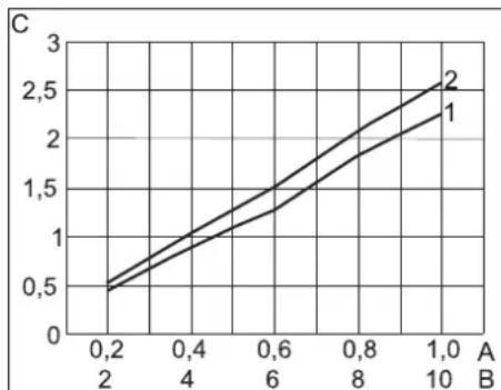
Compressed air demand
line
| X-Axis | Y-Axis (1) | Y-Axis (2) | |---|---|---| | 0.2 | 0.5 | 0.5 | | 0.4 | 0.8 | 1.0 | | 0.6 | 1.2 | 1.5 | | 0.8 | 1.7 | 2.0 | | 1.0 | 2.3 | 2.7 |A Pressure in MPa
B Pressure in bar
C Volume stream in m ^3 /min
1 straight nozzles
2 angled nozzles
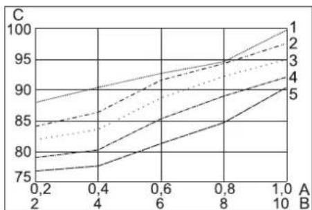
Sound

line
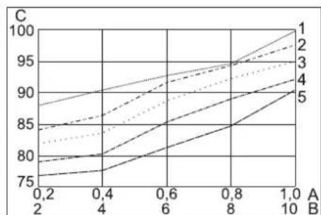
| A | B | C | |---|---|---| | 0.2 | 2 | 85 | | 0.4 | 4 | 86 | | 0.6 | 6 | 89 | | 0.8 | 8 | 93 | | 1.0 | 10 | 97 | The chart displays a single line representing category '1' through category '5'. The x-axis is labeled 'A' and the y-axis is labeled 'B'. The lines are connected by solid, dashed, dotted, and dash-dotted styles to the same y-axis values.A Pressure in MPa
B Pressure in bar
C Noise level in dB(A)
1 Round jet nozzle, short
2 Flat stream nozzle, short
3 Flat jet nozzle, angled
4 Round jet nozzle, long
5 Flat stream nozzle, long, included in delivery
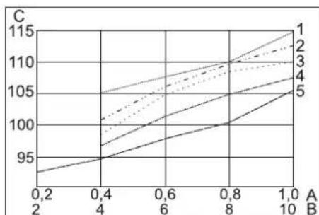
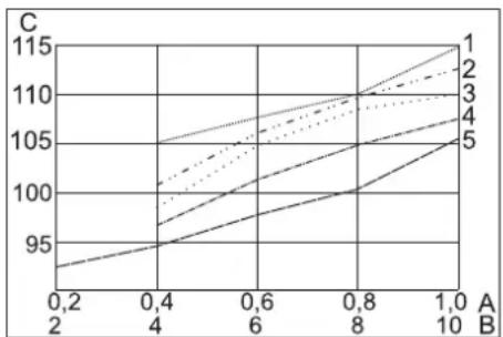
Sound power level

line
| X-Axis | Line 1 | Line 2 | Line 3 | Line 4 | Line 5 | |---|---|---|---|---|---| | 0.2 | 93 | 94 | 98 | 100 | 102 | | 0.4 | 95 | 96 | 100 | 102 | 104 | | 0.6 | 97 | 98 | 102 | 104 | 106 | | 0.8 | 99 | 100 | 104 | 106 | 108 | | 1.0 | 101 | 102 | 106 | 108 | 110 | The chart displays a single data series with x-axis labeled 'A' (ranging from 0.2 to 1.0) and y-axis labeled 'C' (ranging from 93 to 115). The lines are annotated numerically from 1 to 5, indicating sequential data points or categories. No explicit numerical values or trends are provided in the image.A Pressure in MPa
B Pressure in bar
C Noise level in dB(A)
1 Round jet nozzle, short
2 Flat stream nozzle, short
3 Flat jet nozzle, angled
4 Round jet nozzle, long
5 Flat stream nozzle, long, included in delivery
Accessories
Protective clothing
Full view protective goggles, anti-condensation, part no.: 6.321-208.0
Cold protection gloves with anti-slip profile, category III as per EN 511, part no.: 6.321-210.0
Ear protection with headgear, part no.: 6.321-207.0
Jet equipment
Round jet nozzle, short
Part no.: 4.321-236.0
Round jet nozzle, long
Part no.: 4.321-234.0
Flat stream nozzle, short
Part no.: 4.321-237.0
Flat stream nozzle, long, included in delivery
Part no.: 4.321-235.0
Round jet nozzle, angled
Part no.: 4.321-249.0
Flat jet nozzle, angled
Part no.: 4.321-250.0
Scrambler
Part no.: 4.110-015.0
Nozzle extension, 300 mm long
Part no.: 5.760-001.0
Handle
Part no.: 4.321-248.0
Working light
Part no.: 2.815-421.0
Warranty
The warranty terms published by our competent sales company are applicable in each country. We will repair potential failures of your appliance within the warranty period free of charge, provided that such failure is caused by faulty material or defects in fabrication. In the event of a warranty claim please contact your dealer or the nearest authorized Customer Service center. Please submit the proof of purchase.
EU Declaration of Conformity
We hereby declare that the machine described below complies with the relevant basic safety and health requirements of the EU Directives, both in its basic design and construction as well as in the version put into circulation by us. This declaration shall cease to be valid if the machine is modified without our prior approval.
Product: Dry ice jet unit
Type: 1.574-xxx
Relevant EU Directives
2011/65/EU
2006/42/EC (+2009/127/EC)
2014/30/EU
2009/125/EG + 2009/1781
Applied harmonized standards
EN 55014-1: 2017 + A11: 2020
EN 55014-2: 2015
EN 60204-1
EN 61000-3-2: 2014
EN 61000-3-3: 2013
EN IEC 63000: 2018
EN 62233: 2008
Applied national standards
GS-STE-13 (based on it)
The undersigned act on behalf and under the power of attorney of the company management.

Chairman of the Board of Management
Director Regulatory Affairs & Certification
Documentation supervisor:
S. Reiser
Alfred Kärcher SE & Co. KG
71364 Winnenden (Germany)
Tel.: +49 7195 14-0
Fax: +49 7195 14-2212
Winnenden, 2021/02/01
Declaration of Conformity
We hereby declare that the product described below complies with the relevant provisions of the following UK Regulations, both in its basic design and construction as well as in the version put into circulation by us. This declaration shall cease to be valid if the product is modified without our prior approval.
Product: Dry ice jet unit
Type: 1.574-xxx
Currently applicable UK Regulations
S.I. 2012/3032 (as amended)
S.I. 2008/1597 (as amended)
S.I. 2016/1091 (as amended)
2009/125/EC + 2009/1781
Applied designated standards
EN 55014-1: 2017 + A11: 2020
EN 55014-2: 2015
EN 60204-1
EN 61000-3-2: 2014
EN 61000-3-3: 2013
EN IEC 63000: 2018
EN 62233: 2008
Applied national standards
GS-STE-13 (based on it)
The undersigned act on behalf and under the power of attorney of the company management.

Chairman of the Board of Management
Director Regulatory Affairs & Certification
Documentation supervisor:
S. Reiser
Alfred Kärcher SE & Co. KG
71364 Winnenden (Germany)
Tel.: +49 7195 14-0
Fax: +49 7195 14-2212
Winnenden, 2021/02/01
www.kaercher.com/REACH
⚠️Danger
natural_image
Line drawing of a cylindrical mechanical component with flanged ends (no text or symbols)natural_image
Simple line drawing of a bolt and nut (no text or symbols)natural_image
Technical line drawing of a mechanical component with a central shaft and multiple circular holes (no text or symbols)
Chairman of the Board of Management
Director Regulatory Affairs & Certification
71364 Winnenden (Germany)
Tel.: +49 7195 14-0
Fax: +49 7195 14-2212
Winnenden, 2021/02/01
www.kaercher.com/REACH
Norme di sicurezza
⚠ Pericolo
Solo per IB 7/40 Advanced:
natural_image
Line drawing of a cylindrical mechanical component with flanged ends (no text or symbols)natural_image
Simple line drawing of a bolt with a flange and cap (no text or symbols)natural_image
Technical line drawing of a mechanical pulley or wheel assembly (no text or symbols)1 Vite
2 Parte inferiore
3 Dado
4 Disco
5 Inserto filtro
6 Parte superiore
line
| A | B | C | |---|---|---| | 0.2 | 0.4 | 95 | | 0.4 | 0.6 | 100 | | 0.6 | 0.8 | 105 | | 0.8 | 1.0 | 110 | | 1.0 | 1.0 | 115 | The chart displays a single data series with five distinct lines labeled 1 through 5. The x-axis ranges from 0.2 to 1.0, and the y-axis ranges from 95 to 115. There are no labels or additional data series in this image.A Pressione in MPa
B Pressione in bar
Winnenden, 2021/02/01
www.kaercher.com/REACH
⚠️Gevaar
natural_image
Line drawing of a cylindrical mechanical part with flanged ends (no text or symbols)natural_image
Simple line drawing of a bolt and nut (no text or symbols)Werkverlichting (accessoires)
natural_image
Technical line drawing of a mechanical component with a central shaft and multiple circular holes (no text or symbols)line
| A | B | C | |---|---|---| | 0.2 | 2 | 93 | | 0.4 | 4 | 96 | | 0.6 | 6 | 100 | | 0.8 | 8 | 105 | | 1.0 | 10 | 110 | The chart displays a single data series with five distinct lines labeled 1 through 5. The x-axis ranges from 0.2 to 1.0, and the y-axis ranges from 95 to 115. No explicit title or axis labels are provided in the image.
H. Jenner
Chairman of the Board of Management
S. Reiser
Director Regulatory Affairs & Certification
71364 Winnenden (Germany)
Tel.: +49 7195 14-0
Fax: +49 7195 14-2212
Winnenden, 2021/02/01
www.kaercher.com/REACH
⚠Peligro
natural_image
Line drawing of a cylindrical mechanical component with flanged ends (no text or symbols)natural_image
Simple line drawing of a bolt and nut (no text or symbols)natural_image
Technical line drawing of a mechanical component with a central shaft and multiple circular holes (no text or symbols)1 Tornillo
2 Parte inferior
3 Tuerca
4 Arandela
5 Cartucho filtrante
6 Parte superior
line
| X-Axis | Series 1 | Series 2 | |---|---|---| | 0.2 | 0.5 | 0.5 | | 0.4 | 0.8 | 1.0 | | 0.6 | 1.2 | 1.5 | | 0.8 | 1.8 | 2.0 | | 1.0 | 2.3 | 2.7 | A Bline
| A | B | | --- | ---- | | 0.2 | 95 | | 0.4 | 100 | | 0.6 | 105 | | 0.8 | 110 | | 1.0 | 115 |Winnenden, 2021/02/01
www.kaercher.com/REACH
Avisos de segurança
natural_image
Pure graphical symbols representing surveillance, human figures, a dog, and equipment (no text or labels)⚠️Perigo
natural_image
Line drawing of a cylindrical mechanical component with flanged ends (no text or symbols)Punho (acessório)
natural_image
Line drawing of a mechanical bolt with a flanged cap (no text or symbols)natural_image
Technical line drawing of a mechanical component with a central shaft and circular holes (no text or symbols)1 Revestimento lateral
2 Fecho rápido
1 Parafuso
2 Parte inferior
3 Porca
4 Anilha
5 Elemento filtrante
6 Parte superior
line
| A | B | C | |---|---|---| | 0.2 | 2 | 85 | | 0.4 | 4 | 86 | | 0.6 | 6 | 89 | | 0.8 | 8 | 93 | | 1.0 | 10 | 98 | The chart displays a single line representing category '1'. The other lines represent categories '2', '3', '4', and '5' in descending order of value. No explicit numerical values are provided for the series.line
| A | B | C | |---|---|---| | 0.2 | 0.4 | 95 | | 0.4 | 0.6 | 100 | | 0.6 | 0.8 | 105 | | 0.8 | 1.0 | 110 | | 1.0 | 1.0 | 115 | The chart displays a single line representing category '1' through category '5'. The x-axis is labeled 'A' and the y-axis is labeled 'C'. The lines are connected by solid and dotted styles, suggesting different series or conditions.2006/42/CE (+2009/127/CE)
2014/30/UE
2009/125/EG + 2009/1781

Chairman of the Board of Management
Director Regulatory Affairs & Certification
71364 Winnenden (Germany)
Tel.: +49 7195 14-0
Fax: +49 7195 14-2212
Winnenden, 2021/02/01
www.kaercher.com/REACH
Risiko
1 Kabelholder
2 Netkabel med netstik
natural_image
Line drawing of a cylindrical mechanical component with flanged ends (no text or symbols)Håndgreb (tilbehør)
natural_image
Simple line drawing of a bolt and nut (no text or symbols)natural_image
Technical line drawing of a mechanical pulley or wheel assembly (no text or symbols)1 Skrue
2 Bund
3 Møtrik
4 Skive
5 Filterindsats
6 Top
line
| X-Axis | Series 1 | Series 2 | Series 3 | Series 4 | Series 5 | |---|---|---|---|---|---| | 0.2 | 93 | 94 | 98 | 100 | 102 | | 0.4 | 95 | 96 | 100 | 102 | 104 | | 0.6 | 97 | 98 | 102 | 104 | 106 | | 0.8 | 99 | 100 | 104 | 106 | 108 | | 1.0 | 101 | 102 | 106 | 108 | 110 | The chart displays a single data series with x-axis labeled 'A' (ranging from 0.2 to 1.0) and y-axis labeled 'C' (ranging from 93 to 115). The series are labeled numerically from 1 to 5, but their positions are not explicitly defined in the visual field.Dele-nr.: 4.321-235.0
Dele-nr.: 4.321-250.0
Scrambler
Dele-nr.: 4.110-015.0
Dele-nr.: 4.321-248.0
Arbejdsbelysning
Dele-nr.: 2.815-421.0
Garanti
2006/42/EF (+2009/127/EF)
2014/30/EU
2009/125/EG + 2009/1781

Chairman of the Board of Management
S. Reiser
Director Regulatory Affairs & Certification
71364 Winnenden (Germany)
Tel.: +49 7195 14-0
Fax: +49 7195 14-2212
Winnenden, 2021/02/01
www.kaercher.com/REACH
natural_image
Pure graphical symbols representing surveillance, human figures, a dog, and equipment (no text or labels)⚠️Fare!
1 Skyvebøyle
2 Deksel tørrisbeholder
3 Holder for strålepistol
4 Lagringsrom for tilbehør
5 Betjeningspanel
6 Kobling styreledning
7 Jordingskabel med klemme (kun IB 7/40 Advanced, opsjon ved IB 7/40 Classic)
8 Kobling strålemiddelslange
9 Styrerulle med holdebremse
10 Transporthåndtak, rammebeskyttelsesbøyle
11 Tørrisuttak, for tømming av beholderen
1 Dyse
2 Strålepistol
3 Avtrekkerhendel
4 Sikringsknapp
5 Kobling strålemiddelslange
6 Kobling styreledning
Kun for H 7/40 Advanced:
1 Rundstråledyse, kort
2 Rundstråledyse, lang
3 Flatstråledyse, kort
4 Flatstråledyse, lang, del av leveransen
5 Rundstråledyse, vinklet, med gummiarmering
6 Flatstråledyse, vinklet, med gummiarmering
1 Skrueforbindelse
2 Magasin
3 Hullplate
→ Skru av skrueforbindelsen.
natural_image
Line drawing of a cylindrical mechanical component with flanged ends (no text or symbols)Handtak (tilbehør)
Håndtaket kan festes på forlengelsen.
natural_image
Line drawing of a mechanical bolt with a flanged cap (no text or symbols)natural_image
Technical line drawing of a mechanical component with a central shaft and multiple circular holes (no text or symbols)1 ∅ke verdien
2 Redusere verdien
3 Menypunkt oppover
4 Menypunkt nedover
| Menypunkt | Regule-ringsom-råde | Beskrivelse |
| Softstart | 0, 1, 2, 3,4, 5 sek-under | Soft-start, tid til det ønskede stråletrykket nås |
| T_Dump | 1, 2, 3, 4,5 minutter | Tid for tørris-uttøm-mingsprosessen |
| Language | metric,imperial | Måleenheter metric: kg/t, MPa imperial: lbs, psi |
| Lighting | ON/OFF Slå på/av dysebelysnin-gen (alternativ) | |
| Demo-Mode | ON/OFF Dø | demonstrasjonsdrift:Betjening blir simulert, trykkluft- og tørrisleve-ring er sperret. |
Avslutte grunninnstillinger
→ Vri nøkkelbryteren mot urviseren.
Stans av driften
⚠️Fare
Fare for kuldeskader (kuldeforbrenninger). Tørris har en temperatur på -79 °C. Ikke berør tørris eller kalde apparatdeler uten beskyttelse. Bruk vernehansker og vernetøy med lange ermer.
⚠️Fare
1 Skrue
2 Underdel
3 Mutter
4 Skive
5 Filterinnsats
6 Overdel
line
| X-Axis | Y-Axis Label | Line Type | |---|---|---| | 0.2 | 0.5 | 1 | | 0.2 | 0.5 | 2 | | 0.4 | 0.8 | 1 | | 0.4 | 0.9 | 2 | | 0.6 | 1.2 | 1 | | 0.6 | 1.3 | 2 | | 0.8 | 1.7 | 1 | | 0.8 | 1.9 | 2 | | 1.0 | 2.3 | 1 | | 1.0 | 2.6 | 2 |A Trykk i MPa
B Trykk i bar
C Volumstrøm i m 3/min
1 rette dyser
2 vinklede dyser
Lydtrykksnivå
line
| X-Axis | Line 1 | Line 2 | Line 3 | Line 4 | Line 5 | |---|---|---|---|---|---| | 0.2 | 85 | 84 | 82 | 80 | 78 | | 0.4 | 86 | 86 | 84 | 81 | 79 | | 0.6 | 88 | 89 | 87 | 83 | 81 | | 0.8 | 90 | 92 | 90 | 85 | 83 | | 1.0 | 92 | 95 | 93 | 87 | 85 | | 10 | 95 | 98 | 95 | 90 | 88 |A Trykk i MPa
B Trykk i bar
C Lydtrykksnivå i dB(A)
1 Rundstråledyse, kort
2 Flatstråledyse, kort
3 Flatstråledyse, vinklet
4 Rundstråledyse, lang
5 Flatstråledyse, lang, del av leveransen
Lydeffektsnivå
line
| A | B | | --- | ---- | | 0.2 | 95 | | 0.4 | 100 | | 0.6 | 105 | | 0.8 | 110 | | 1.0 | 115 |A Trykk i MPa
B Trykk i bar
C Lydeffektsnivå i dB(A)
1 Rundstråledyse, kort
2 Flatstråledyse, kort
3 Flatstråledyse, vinklet
4 Rundstråledyse, lang
5 Flatstråledyse, lang, del av leveransen
Tilbehør
Vernedrakt
Winnenden, 2021/02/01
www.kaercher.com/REACH
⚠️Fara
1 Munstycke
2 Strålspruta
3 Startspak
4 Låsknapp
5 Koppling med strålmedelslang
natural_image
Line drawing of a cylindrical mechanical component with flanged ends (no text or symbols)Handtag (tillbehör)
natural_image
Simple line drawing of a bolt and nut (no text or symbols)natural_image
Technical line drawing of a mechanical pulley or wheel component (no text or symbols)1 Öka värde
2 Minska värde
3 Menypunkt uppåt
4 Menypunkt neråt
Chairman of the Board of Management
Director Regulatory Affairs & Certification
71364 Winnenden (Germany)
Tel.: +49 7195 14-0
Fax: +49 7195 14-2212
Winnenden, 2021/02/01
www.kaercher.com/REACH
Turvaohjeet
natural_image
Pure graphical symbols representing surveillance, human figures, a dog, and equipment (no text or labels)⚠ Vaara
natural_image
Line drawing of a cylindrical mechanical part with flanged ends (no text or symbols)natural_image
Simple line drawing of a bolt with a flanged cap (no text or symbols)natural_image
Technical line drawing of a mechanical pulley or wheel assembly (no text or symbols)1 Sivuverhous
2 Pikakiinnitin

Chairman of the Board of Management
Director Regulatory Affairs & Certification
71364 Winnenden (Germany)
Tel.: +49 7195 14-0
Fax: +49 7195 14-2212
Winnenden, 2021/02/01
⚠️Κίνδυνος
natural_image
Line drawing of a cylindrical mechanical component with flanged ends (no text or symbols)natural_image
Line drawing of a bolt with a flanged cap (no text or symbols)natural_image
Technical line drawing of a mechanical component with a central shaft and multiple circular holes (no text or symbols)line
| X-Axis | Line 1 | Line 2 | Line 3 | Line 4 | Line 5 | |---|---|---|---|---|---| | 0.2 | 93 | 94 | 98 | 100 | 102 | | 0.4 | 96 | 97 | 100 | 102 | 104 | | 0.6 | 99 | 100 | 103 | 105 | 106 | | 0.8 | 102 | 103 | 106 | 108 | 108 | | 1.0 | 105 | 106 | 109 | 110 | 110 | The chart displays a single data series with x-axis labeled 'A' (ranging from 0.2 to 1.0) and y-axis labeled 'C' (ranging from 93 to 115). The lines are annotated numerically from 1 to 5, indicating sequential data points or categories. No explicit numerical values or trends are provided for the plotted data.
Chairman of the Board of Management

S. Reiser
Director Regulatory Affairs & Certification
71364 Winnenden (Germany)
Tel.: +49 7195 14-0
Fax: +49 7195 14-2212
Winnenden, 2021/02/01
www.kaercher.com/REACH
Güvenlik uyarıları
natural_image
Pure graphical symbols representing surveillance, human figures, a dog, and a device (no text or labels)Tehlike
1 Kablo tutucu
natural_image
Line drawing of a cylindrical mechanical component with flanged ends (no text or symbols)Tutamak (aksesuar)
natural_image
Simple line drawing of a bolt and nut (no text or symbols)natural_image
Technical line drawing of a mechanical pulley or wheel component (no text or symbols)1 Yan kaplama
2 Mandal
1 Civata
2 Alt parça
3 Somun
4 Pul
5 Filtre kartuşu
6 Üst parça
line
| A | B | C | |---|---|---| | 0.2 | 0.4 | 95 | | 0.4 | 0.6 | 100 | | 0.6 | 0.8 | 105 | | 0.8 | 1.0 | 110 | | 1.0 | 1.0 | 115 | The chart displays a single line representing category '1'. The other lines represent categories '2', '3', '4', and '5' in descending order of value. No explicit numerical values are provided for the series.
Chairman of the Board of Management

Director Regulatory Affairs & Certification
71364 Winnenden (Germany)
Tel.: +49 7195 14-0
Fax: +49 7195 14-2212
Winnenden, 2021/02/01
www.kaercher.com/REACH
⚠️ Опасность
natural_image
Line drawing of a cylindrical mechanical component with flanged ends (no text or symbols)natural_image
Line drawing of a mechanical bolt with a flanged cap (no text or symbols)natural_image
Technical line drawing of a mechanical pulley or wheel assembly (no text or symbols)line
| A | B | C | |---|---|---| | 0.2 | 0.4 | 95 | | 0.4 | 0.6 | 100 | | 0.6 | 0.8 | 105 | | 0.8 | 1.0 | 110 | | 1.0 | 1.0 | 115 | The chart displays a single data series with five distinct lines labeled 1 through 5. The x-axis ranges from 0.2 to 1.0, and the y-axis ranges from 95 to 115. There are no labels or additional data series in this image.А Давление в МПа
В Давление в барах
Winnenden, 2021/02/01
www.kaercher.com/REACH
Biztonsági tanácsok
⚠ Veszély
1 Tolókengyel
1 Kábel tartó
1 Csavarzat
2 Tár
3 Lyukaslemez
natural_image
Line drawing of a cylindrical mechanical component with flanged ends (no text or symbols)Fogantyú (tartozék)
natural_image
Line drawing of a mechanical bolt with a flanged cap (no text or symbols)natural_image
Technical line drawing of a mechanical component with a central shaft and circular holes (no text or symbols)
Chairman of the Board of Management
Director Regulatory Affairs & Certification
Winnenden, 2021/02/01
www.kaercher.com/REACH
Bezpečnostní pokyny
⚠️Nebezpečí
1 Držák kabelu
Pouze u IB 7/40 Advanced:
natural_image
Line drawing of a cylindrical mechanical component with flanged ends (no text or symbols)natural_image
Simple line drawing of a bolt and nut (no text or symbols)natural_image
Technical line drawing of a mechanical pulley or wheel component (no text or symbols)line
| A | B | C | |---|---|---| | 0.2 | 2 | 85 | | 0.4 | 4 | 86 | | 0.6 | 6 | 89 | | 0.8 | 8 | 93 | | 1.0 | 10 | 98 | The chart displays a single line representing category '1'. The other lines represent categories '2', '3', '4', and '5' in descending order of value. No explicit numerical values are provided for the series.2006/42/ES (+2009/127/ES)
2014/30/EU
2009/125/EG + 2009/1781

Chairman of the Board of Management

S. Reiser
Director Regulatory Affairs & Certification
71364 Winnenden (Germany)
Tel.: +49 7195 14-0
Fax: +49 7195 14-2212
Winnenden, 2021/02/01
www.kaercher.com/REACH
Varnostna navodila
⚠️ Nevarnost
1 Nosilec kabla
2 Omrežni kabel z omrežnim vtičem
1 Navojni spoj
2 Magazin
3 Luknjasta plošča
natural_image
Line drawing of a cylindrical mechanical component with flanged ends (no text or symbols)Ročaj (pribor)
natural_image
Simple line drawing of a bolt and nut (no text or symbols)natural_image
Technical line drawing of a mechanical pulley or wheel component (no text or symbols)1 Stranska obloga
2 Hitro zapiralo
→ Hitro zapiralo odprite v nasprotni smeri urnega kazalca.
→ Snemite stransko oblogo.
Vzdrževanje
1 Vijak
2 Spodnji del
3 Matica
4 Kolut
5 Filtrni vložek
6 Zgornji del
→ Izvijte 4 vijake.
→ Snemite spodnji del.
→ Odvijte matice.
→ Odstranite kolut.
→ Snemite filtrni vložek in ga zamenjajte novim filtrnim vložkom.
→ Vodni ločevalnik ponovno sestavite v obratnem vrstnem redu.
Pregledi
V skladu z BGV D 26 mora strokovnjak na napravi opraviti naslednje preglede. Rezultate pregleda je potrebno podati pisno v Potrdilu o pregledu. Potrdilo o pregledu mora upravljavec naprave shraniti do naslednjega pregleda.
line
| A | B | C | |---|---|---| | 0.2 | 0.4 | 95 | | 0.4 | 0.6 | 100 | | 0.6 | 0.8 | 105 | | 0.8 | 1.0 | 110 | | 1.0 | 1.0 | 115 | The chart displays a single line representing category '1' through category '5'. The x-axis is labeled 'A' and the y-axis is labeled 'C'. The lines are connected by solid and dashed lines, suggesting different series or conditions. No explicit numerical values are provided for the data points.2006/42/ES (+2009/127/ES)
2014/30/EU
2009/125/EG + 2009/1781

Chairman of the Board of Management

Director Regulatory Affairs & Certification
71364 Winnenden (Germany)
Tel.: +49 7195 14-0
Fax: +49 7195 14-2212
Winnenden, 2021/02/01
www.kaercher.com/REACH
⚠ Niebezpieczeństwo
natural_image
Line drawing of a cylindrical mechanical component with flanged ends (no text or symbols)Uchwyt (akcesoria)
natural_image
Simple line drawing of a bolt and nut (no text or symbols)natural_image
Technical line drawing of a mechanical pulley or wheel component (no text or symbols)line
| A | B | C | |---|---|---| | 0.2 | 0.4 | 95 | | 0.4 | 0.6 | 100 | | 0.6 | 0.8 | 105 | | 0.8 | 1.0 | 110 | | 1.0 | 1.0 | 115 | The chart displays a single data series with five distinct lines labeled 1 through 5. The x-axis ranges from 0.2 to 10, and the y-axis ranges from 95 to 115. There are no explicit title or axis labels provided in the image.2006/42/WE (+2009/127/WE)
2014/30/UE
2009/125/EG + 2009/1781
71364 Winnenden (Germany)
Tel.: +49 7195 14-0
Fax: +49 7195 14-2212
Winnenden, 2021/02/01
www.kaercher.com/REACH
Măsuri de siguranță
⚠️ Pericol
natural_image
Line drawing of a cylindrical mechanical component with flanged ends (no text or symbols)Mâner (accesoriu)
natural_image
Simple line drawing of a bolt with a flange and cap (no text or symbols)natural_image
Technical line drawing of a mechanical component with a central shaft and multiple circular holes (no text or symbols)1 Mărirea valorii
2 Micşorarea valorii
3 Punctul de meniu de mai sus
4 Punctul de meniu de mai jos
line
| X-Axis | Series 1 | Series 2 | |---|---|---| | 0.2 | 0.5 | 0.5 | | 0.4 | 1.0 | 1.0 | | 0.6 | 1.3 | 1.5 | | 0.8 | 1.8 | 2.0 | | 1.0 | 2.3 | 2.7 |A Presiune (MPa)
B Presiune (bar)
C Flux volumic (m 3/min)
1 Duze drepte
2 duze cotite
Nivel de zgomot
line
| A | B | | ---- | ---- | | 0.2 | 85 | | 0.4 | 87 | | 0.6 | 90 | | 0.8 | 93 | | 1.0 | 95 | | 10 | 97 |line
| A | B | | --- | ---- | | 0.2 | 95 | | 0.4 | 100 | | 0.6 | 105 | | 0.8 | 110 | | 1.0 | 115 |Directive UE respectate:
2011/65/EU
2006/42/CE (+2009/127/CE)
2014/30/UE
2009/125/EG + 2009/1781
Norme armonizate utilize:
EN 55014-1: 2017 + A11: 2020
EN 55014-2: 2015
EN 60204-1
EN 61000-3-2: 2014
EN 61000-3-3: 2013
EN IEC 63000: 2018
EN 62233: 2008

Chairman of the Board of Management

S. Reiser
Director Regulatory Affairs & Certification
71364 Winnenden (Germany)
Tel.: +49 7195 14-0
Fax: +49 7195 14-2212
Winnenden, 2021/02/01
⚠️Nebezpečenstvo
Len u IB 7/40 Advanced:
1 Zvýšenie hodnoty
2 Zníženie hodnoty
3 Bod menu smerom hore
4 Bod menu smerom dole
line
| A | B | C | |---|---|---| | 0.2 | 2 | 85 | | 0.4 | 4 | 86 | | 0.6 | 6 | 89 | | 0.8 | 8 | 93 | | 1.0 | 10 | 98 | The chart displays a single line representing category '1' through category '5'. The x-axis is labeled 'A' and the y-axis is labeled 'B'. The lines are connected by solid, dashed, dotted, and dash-dotted styles to the right side of the plot.line
| A | B | C | |---|---|---| | 0.2 | 0.4 | 95 | | 0.4 | 0.6 | 100 | | 0.6 | 0.8 | 105 | | 0.8 | 1.0 | 110 | | 1.0 | 1.0 | 115 | The chart displays a single line representing category '1' through category '5'. The x-axis is labeled 'A' and the y-axis is labeled 'C'. The lines are connected by solid and dashed lines, suggesting different trends or conditions for each category.2006/42/ES (+2009/127/ES)
2014/30/EU
2009/125/EG + 2009/1781
Uplatňované harmonizované normy:
EN 55014-1: 2017 + A11: 2020
EN 55014-2: 2015
EN 60204-1
EN 61000-3-2: 2014
EN 61000-3-3: 2013
EN IEC 63000: 2018
EN 62233: 2008

Chairman of the Board of Management
Director Regulatory Affairs & Certification
71364 Winnenden (Germany)
Tel.: +49 7195 14-0
Fax: +49 7195 14-2212
Winnenden, 2021/02/01
Prije prve uporabe Vašeg uređaja pročitajte ove originalne radne upute, postupajte prema njima i sačuvajte ih za kasniju uporabu ili za sljedećeg vlasnika.
Pregled sadržaja
www.kaercher.com/REACH
Sigurnosni napuci
natural_image
Pure graphical symbols representing surveillance, human figures, a dog, and other objects without any text or labels⚠️ Opasnost
1 Potisna ručica
2 Poklopac spremnika za suhi led
3 Držač za brizgaljku
4 Odjeljak za pribor
5 Komandno polje
6 Kvačilo upravljačkog voda
7 Žica za uzemljenje sa stezaljkom (samo IB 7/40 Advanced, opcija kod IB 7/40 Classic)
8 Spojka crijeva za sredstvo za brizganje
9 Kotačić s pozicijskom kočnicom
10 Transportni rukohvat, zaštitni luk od udara
11 Izlaz za suhi led, za pražnjenje spremnika
1 Držač kabela
2 Strujni kabel sa strujnim utikačem
3 Dekompresijski ventil, pražnjenje kondenzata odvajača za kondenzat
4 Priključak za komprimirani zrak
5 Ispust kondenzata
6 Osigurač F1, ispod bočne oplate
Komandno polje
1 Mlaznica
2 Brizgaljka
3 Poluga okidača
4 Sigurnosni gumb
5 Spojka crijeva za sredstvo za brizganje
1 Vijčani spoj
2 Spremnik
3 Rupičasta ploča
natural_image
Line drawing of a cylindrical mechanical component with flanged ends (no text or symbols)Rukohvat (pribor)
Rukohvat se može pričvrstiti na produžetku.
natural_image
Simple line drawing of a bolt and nut (no text or symbols)Radno svjetlo (pribor)

natural_image
Technical line drawing of a mechanical pulley or wheel component (no text or symbols)1 Bočna oplata
2 Bravica
1 Vijak
2 Donji dio
3 Matica
4 Pločica
5 Filtarski umetak
6 Gornji dio
→ Odvijte 4 vijka.
→ Skinite donji dio.
→ Odvijte maticu.
→ Skinite pločicu.
→ Filtarski umetak skinite i zamijenite novim filtarskim umetkom.
→ Separator vode ponovno sastavite obr nutim redoslijedom.
provjeravanje
line
| X-Axis | Y-Axis (C) - Line 1 | Y-Axis (C) - Line 2 | |---|---|---| | 0.2 | 0.5 | 0.5 | | 0.4 | 1.0 | 1.0 | | 0.6 | 1.3 | 1.4 | | 0.8 | 1.8 | 2.0 | | 1.0 | 2.3 | 2.6 |line
| A | B | C | |---|---|---| | 0.2 | 2 | 84 | | 0.2 | 4 | 86 | | 0.2 | 6 | 89 | | 0.2 | 8 | 93 | | 0.2 | 10 | 96 | | 0.4 | 2 | 80 | | 0.4 | 4 | 82 | | 0.4 | 6 | 85 | | 0.4 | 8 | 88 | | 0.4 | 10 | 91 | | 0.6 | 2 | 78 | | 0.6 | 4 | 81 | | 0.6 | 6 | 84 | | 0.6 | 8 | 89 | | 0.6 | 10 | 92 | | 0.8 | 2 | 85 | | 0.8 | 4 | 88 | | 0.8 | 6 | 91 | | 0.8 | 8 | 94 | | 0.8 | 10 | 97 | | 1.0 | 2 | 79 | | 1.0 | 4 | 81 | | 1.0 | 6 | 84 | | 1.0 | 8 | 89 | | 1.0 | 10 | 92 | | B (top axis) | C (bottom axis) | Line series labeled numerically (1 to 5). The chart displays a single horizontal line at value C = 1, indicating a constant value across all lines for each of the plotted lines. No trends or comparisons can be derived from the provided image. The legend is implicit in the line labels.line
| A | B | C | |---|---|---| | 0.2 | 2 | 93 | | 0.4 | 4 | 96 | | 0.6 | 6 | 100 | | 0.8 | 8 | 105 | | 1.0 | 10 | 110 | | 1.0 | 10 | 115 | The chart displays a single data series with five distinct lines labeled 1 through 5, each representing a separate series of values across the x-axis range. The y-axis is labeled 'C'. The lines are connected by solid and dotted lines, suggesting different trends or conditions for each series.
Chairman of the Board of Management
S. Reiser
Director Regulatory Affairs & Certification
71364 Winnenden (Germany)
Tel.: +49 7195 14-0
Fax: +49 7195 14-2212
Winnenden, 2021/02/01
Pre prve upotrebe Vašeg uređaja pročitajte ove originalno uputstvo za rad, postupajte prema njemu i sačuvajte ga za kasniju upotrebu ili za sledećeg vlasnika.
Pregled sadržaja
www.kaercher.com/REACH
Sigurnosne napomene
Uređaj se smije koristiti samo od osoba, koje su pročitale upustvo za upotrebu i koji su je razumjeli. Moraju se uvažavati sve sigurnosne napomene.
→ Upustvo za upotrebu čuvati na taj način, tako da je korisniku dostupna u svakom trenutku.
Stepeni opasnosti
⚠️ Opasnost
Ukazuje na neposredno preteću opasnost koja dovodi do teških telesnih povreda ili smrti.
⚠ Upozorenje
Ukazuje na eventualno opasnu situaciju koja može dovesti do teških telesnih povreda ili smrti.
Oprez
Ukazuje na eventualno opasnu situaciju koja može dovesti do lakših telesnih povreda ili izazvati materijalnu štetu.
Simboli na aparatu
natural_image
Pure graphical symbols representing surveillance, human figures, a dog, and equipment (no text or labels)⚠️ Opasnost
Opasnost od povrede kroz leteće pelete suhog leda. Mlazni pištolj ne uperivati na osobe. Ostale osobe udaljiti od mjesta obavljana rada i udaljiti ih od mjesta dok je mašina u pogonu (npr. kroz ograničavanje).
Tokom pogona na dirati pipu ili u Trockeneisstrahl.
⚠️ Opasnost
Opasnost od trovana kroz ugljen dioksid. Pelete suhog leda se sastoje od čvrstog ugljen dioksida. Kod pogona uređaja raste količina ugljen dioksida u zraku na radnom mestu. Radno mesto dovoljno izračiti, po potrebi koristiti uređaj za upozorenje osoblja. Znak visoke koncentracije ugljen dioksida u zraku:
- 3...5%: Glavobolja, visoka frekvencija disanja.
- 7...10%: Glavobolja, povraćanje i eventualno gubljenje svesti.
Kod pojave ovih naznaka uređaj odmah ugasiti i izaći na svež zrak, prije nastavka rada poboljšati mere prozračivanja ili koristiti uređaj za disanje.
Ugljendioksid je teži od vazduha i sakuplja se u uskim, niskim prostorima ili u zatvorenim posudama.
Pobrinite se za dovoljnu ventilaciju na radnom mestu.
1 Potisna ručica
2 Poklopac rezervoara za suhi led
3 Držač za mlazni pištolj
4 Pregrada za odlaganje pribora
5 Komandno polje
6 Spojnica voda upravljača
7 Žica za uzemljenje sa stezaljkom (samo IB 7/40 Advanced, opcija kod IB 7/40 Classic)
8 Spojnica cijevi mlaznog sredstva
9 Točkić sa pozicionom kočnicom
10 Transportna ruka, Rammschutzbügel
11 Izlaz za suhi led, za ispražnjavanje rezevoara
1 Držač kabla
2 Strujni kabl sa utikačem
3 Dekompresioni ventil, pražnjenje kondenzata odvajača za kondenzat
4 Priključak zraka pod pritiskom
5 Izlaz kondenzata
6 Osigurač F1, ispod bočne oplate
Komandno polje
1 Brizgaljka
2 Mlazni pištolj
3 Okidač
4 Sigurnosno dugme
5 Spojnica cijevi mlaznog sredstva
6 Spojnica voda upravljača
7 Tipka za doziranje suhog leda upaljeno / ugašeno
Svetli crveno kod ugašenov doziranja suhog leda
8 Povećati tipku za doziranje suhog leda.
9 Povećati tipku za mlazni pritisak.
10 Umanjiti tipku za mlazni pritisak.
11 Umanjiti tipku za doziranje suhog leda.
Samo kod IB 7/40 Advanced:
Stavljanje u pogon
⚠️ Opasnost
1 Zavrtni spoj
2 magazin
3 rupčasta ploča
natural_image
Line drawing of a cylindrical mechanical component with flanged ends (no text or symbols)Drška (pribor)
Drška može na produženju biti pričvrsčena.
natural_image
Simple line drawing of a bolt and nut (no text or symbols)natural_image
Technical line drawing of a mechanical pulley or wheel assembly (no text or symbols)Radno osvetljenje se montira između mlaznog pištolja i pipe. Paljenje i gašenje je opisano u poglavlju "Upravljanje/osnovne postavke".
1 Povećati vrednost
2 Smanjiti vrednost
3 Tačku menija prema gore
4 Tačku menija prema dole
| Tačka menija | Raspon podešavanja | Opis |
| Soft početak | 0, 1, 2, 3, 4, 5 sekunde | Lagani start, trjanje do dostizanja izabranog pritiska mlaza |
| T_Dump | 1, 2, 3, 4,5 minuta | Trajanje procesa ispražnjavanja suhog leda |
| jezik | metric, imperial | jedinice merenja metric: kg/h, MPa imperial: lbs, psi |
| osvetljenje | Paljenje/ gašenje | Osvetljenje pipe (opcija) upaliti / gasiti |
| Demo-Modus | Paljenje/ gašenje | Pogon za demonstraciju: Upravljanje se simulira, izlaz zraka pod pritiskomi suhog leda se ograničava. |
1 Bočna oplata
2 Bravica
→ Bravicu otvorite u smeru suprotno od kazaljke na satu.
→ Skinite bočnu oplatu.
Radovi na održavanju
Filter zameniti u rezaču vode
1 Zavrtanj
2 Donji deo
3 Navrtka
4 Pločica
5 Filter
6 Gornji deo
→ Odvijte 4 zavrtnja.
→ Skinuti donji deo.
→ Maticu odvrnuti
line
| X-Axis | Line 1 | Line 2 | Line 3 | Line 4 | Line 5 | |---|---|---|---|---|---| | 0.2 | 88 | 85 | 82 | 80 | 78 | | 0.4 | 90 | 87 | 84 | 81 | 79 | | 0.6 | 92 | 89 | 86 | 83 | 81 | | 0.8 | 94 | 91 | 88 | 85 | 83 | | 1.0 | 96 | 93 | 90 | 87 | 85 | | 2 | - | - | - | - | - | | 4 | - | - | - | - | - | | 6 | - | - | - | - | - | | 8 | - | - | - | - | - | | 10 | - | - | - | - | - | The chart displays a single data series with values for each category (A, B). The y-axis is labeled 'C' and the x-axis is labeled 'B'. There are no labels or additional data series in this image.A Pritisak u MP
B Pritisak u barima
C Nivo zvučnog pritiska u dB(A)
1 Pipa za okrugli mlaz, kratka
2 Pipa za ravni mlaz, kratka
3 Ravna mlazna pipa, kutna
4 Pipa za okrugli mlaz, duga
5 Pipa za ravni mlaz, duga, u okviru dostave
Nivo zvučne snage
line
| A | B | C | |---|---|---| | 0.2 | 93 | 94 | | 0.4 | 96 | 98 | | 0.6 | 99 | 102 | | 0.8 | 102 | 106 | | 1.0 | 105 | 110 | | 10 | 108 | 114 |A Pritisak u MP
B Pritisak u barima
C Nivo zvučnog pritiska u dB(A)
1 Pipa za okrugli mlaz, kratka
2 Pipa za ravni mlaz, kratka
3 Ravna mlazna pipa, kutna
4 Pipa za okrugli mlaz, duga
5 Pipa za ravni mlaz, duga, u okviru dostave
Pribor
Zaštitna odeća
Zaštitne naočale za potpuni pregled, otporno na udar, broj dela: 6.321-208.0 Zaštitne rukavice za hladnoću sa antiklizećimprofilom, kategorija III po EN 511, broj dela: 6.321-210.0 Zaštita za uši sam slušalicama, broj dela: 6.321-207.0
Mlazni uređaj
Pipa za okrugli mlaz, kratka
Kataloški br.: 4.321-236.0
2006/42/EZ (+2009/127/EZ)
2014/30/EU
2009/125/EG + 2009/1781

Chairman of the Board of Management
Director Regulatory Affairs & Certification
71364 Winnenden (Germany)
Tel.: +49 7195 14-0
Fax: +49 7195 14-2212
Winnenden, 2021/02/01
www.kaercher.com/REACH
natural_image
Collection of symbolic icons including a lightning bolt, human figures, a dog, and a battery (no text or labels)⚠️ Опасност
1 Завинтване
2 Магазин
3 Перфорирана пластина
natural_image
Line drawing of a cylindrical mechanical part with flanged ends (no text or symbols)natural_image
Simple line drawing of a cylindrical object with a flanged top and lid (no text or symbols)natural_image
Technical line drawing of a mechanical pulley or wheel assembly (no text or symbols)line
| A | B | C | |---|---|---| | 0.2 | 2 | 85 | | 0.4 | 4 | 86 | | 0.6 | 6 | 89 | | 0.8 | 8 | 93 | | 1.0 | 10 | 98 | The chart displays a single line representing category '1'. The other lines represent categories '2', '3', '4', and '5' in descending order of value. No explicit numerical values are provided for the series.line
| A | B | C | |---|---|---| | 0.2 | 0.4 | 95 | | 0.4 | 0.6 | 100 | | 0.6 | 0.8 | 105 | | 0.8 | 1.0 | 110 | | 1.0 | 1.0 | 115 | The chart displays a single line representing category '1'. The other lines represent categories '2', '3', '4', and '5' in descending order of value. No explicit numerical values are provided for the series.
Chairman of the Board of Management

S. Reiser
Director Regulatory Affairs & Certification
71364 Winnenden (Germany)
Tel.: +49 7195 14-0
Fax: +49 7195 14-2212
Winnenden, 2021/02/01
www.kaercher.com/REACH
natural_image
Pure graphical symbols representing surveillance, human figures, a dog, and equipment (no text or labels)⚠️Oht
natural_image
Line drawing of a cylindrical mechanical component with flanged ends (no text or symbols)Käepide (tarvikud)
natural_image
Line drawing of a mechanical bolt with a flanged cap (no text or symbols)natural_image
Technical line drawing of a mechanical pulley or wheel assembly (no text or symbols)1 Küljepaneel
2 Kiirlukk
1 Kruvi
2 Alumine osa
3 Mutter
4 Seib
5 Filtripadrun
6 Ülemine osa
line
| A | B | C | |---|---|---| | 0.2 | 2 | 93 | | 0.4 | 4 | 96 | | 0.6 | 6 | 100 | | 0.8 | 8 | 105 | | 1.0 | 10 | 110 | The chart displays a single data series with five distinct lines labeled 1 through 5. The x-axis ranges from 0.2 to 10, and the y-axis ranges from 95 to 115. No explicit title or axis labels are provided in the image.A Rõhk (MPa)
B Rõhk (baari)
C Müratase, dB (A)
1 Ümardüüs, lühike
2 Lamedüüs, lühike
3 Lamedüüs, nurga all
4 Ümardüüs, pikk
5 Lamedüüs, pikk, tarnekomplektis
Tarvikud
Kaitseriietus
Chairman of the Board of Management

S. Reiser
Director Regulatory Affairs & Certification
71364 Winnenden (Germany)
Tel.: +49 7195 14-0
Fax: +49 7195 14-2212
Winnenden, 2021/02/01
www.kaercher.com/REACH
Drošības norādījumi
⚠ Bīstami
Tikai IB 7/40 Advanced:
natural_image
Line drawing of a cylindrical mechanical component with flanged ends (no text or symbols)natural_image
Simple line drawing of a bolt with a flanged cap (no text or symbols)natural_image
Technical line drawing of a mechanical component with a central shaft and multiple circular holes (no text or symbols)1 Skrūve
2 Apakšdaļa
3 Uzgrieznis
4 Paplāksne
5 Filtra ieliktnis
6 Augšdaļa
line
| A | B | C | |---|---|---| | 0.2 | 2 | 84 | | 0.2 | 4 | 86 | | 0.2 | 6 | 89 | | 0.2 | 8 | 93 | | 0.2 | 10 | 96 | | 0.4 | 2 | 80 | | 0.4 | 4 | 82 | | 0.4 | 6 | 85 | | 0.4 | 8 | 88 | | 0.4 | 10 | 91 | | 0.6 | 2 | 81 | | 0.6 | 4 | 83 | | 0.6 | 6 | 86 | | 0.6 | 8 | 90 | | 0.6 | 10 | 93 | | 0.8 | 2 | 84 | | 0.8 | 4 | 87 | | 0.8 | 6 | 89 | | 0.8 | 8 | 93 | | 0.8 | 10 | 95 | | 1.0 | 2 | 79 | | 1.0 | 4 | 81 | | 1.0 | 6 | 83 | | 1.0 | 8 | 87 | | 1.0 | 10 | 90 | | B: The chart displays a single data series (line labels) for each of the five series (labeled as '1' to '5'). The x-axis is labeled 'A' and the y-axis is labeled 'B'. The values for each line are explicitly labeled on the chart.A Spiediens megapaskālos (MPa)
B Spiediens bāros (bar)
C Trokšna spiediena līmenis dB(A)
1 Apaļas strūklas sprausla, īsa
2 Plakanstrūklas sprausla, īsa
3 Plakanstrūklas sprausla, sagriezta lenkī
4 Apaļas strūklas sprausla, gara
5 Plakanstrūklas sprausla, gara, piegā-
des komplektā

Chairman of the Board of Management
S. Reiser
Director Regulatory Affairs & Certification
71364 Winnenden (Germany)
Tel.: +49 7195 14-0
Fax: +49 7195 14-2212
Winnenden, 2021/02/01
www.kaercher.com/REACH
Saugos reikalavimai
natural_image
Pure graphical symbols representing human, animals, and equipment without any text or labels⚠️Pavojus
natural_image
Line drawing of a cylindrical mechanical component with flanged ends (no text or symbols)Rankena (priedas)
natural_image
Simple line drawing of a bolt and nut (no text or symbols)natural_image
Technical line drawing of a mechanical pulley or wheel component (no text or symbols)1 Varžtas
2 Apatinė dalis
3 Veržlé
4 Diskas
5 Filtro kasetė
6 Viršutinė dalis
line
| A | B | C | |---|---|---| | 0.2 | 2 | 84 | | 0.2 | 4 | 86 | | 0.2 | 6 | 89 | | 0.2 | 8 | 93 | | 0.2 | 10 | 96 | | 0.4 | 2 | 80 | | 0.4 | 4 | 82 | | 0.4 | 6 | 85 | | 0.4 | 8 | 88 | | 0.4 | 10 | 91 | | 0.6 | 2 | 81 | | 0.6 | 4 | 83 | | 0.6 | 6 | 86 | | 0.6 | 8 | 90 | | 0.6 | 10 | 93 | | 0.8 | 2 | 84 | | 0.8 | 4 | 87 | | 0.8 | 6 | 89 | | 0.8 | 8 | 93 | | 0.8 | 10 | 95 | | 1.0 | 2 | 79 | | 1.0 | 4 | 81 | | 1.0 | 6 | 83 | | 1.0 | 8 | 87 | | 1.0 | 10 | 90 | | B: The chart displays a single data series (line labels) for each of the five series (labeled as '1' to '5') plotted against an unlabeled X-axis (A) and Y-axis (C). The values for each line are explicitly labeled on the chart.
Chairman of the Board of Management
Director Regulatory Affairs & Certification
71364 Winnenden (Germany)
Tel.: +49 7195 14-0
Fax: +49 7195 14-2212
Winnenden, 2021/02/01
⚠️Обережно!
natural_image
Line drawing of a cylindrical mechanical component with flanged ends (no text or symbols)Рукоятка (аксесуар)
natural_image
Line drawing of a mechanical bolt with a flanged cap (no text or symbols)natural_image
Technical line drawing of a mechanical pulley or wheel assembly (no text or symbols)Winnenden, 2021/02/01
www.kaercher.com/REACH
安全说明
△ 危险
1 螺旋连接
2 料仓
3 孔板
natural_image
Line drawing of a cylindrical mechanical component with flanged ends (no text or symbols)手柄(配件)
手柄可以固定到加长件上。
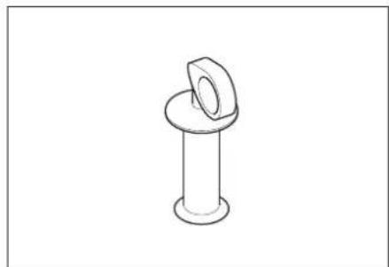
natural_image
Line drawing of a mechanical bolt with a flanged cap (no text or symbols)工作照明(配件)
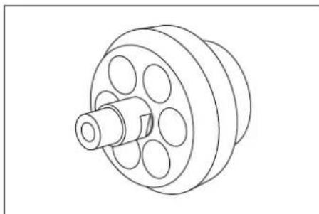
natural_image
Technical line drawing of a mechanical pulley or wheel component (no text or symbols)1 增大数值
2 减小数值
3 菜单项向上
4 菜单项向下
1 侧板
2 快速封扣
line
| X-Axis | Series 1 | Series 2 | |---|---|---| | 0.2 | 0.5 | 0.5 | | 0.4 | 0.8 | 1.0 | | 0.6 | 1.2 | 1.5 | | 0.8 | 1.7 | 2.0 | | 1.0 | 2.3 | 2.6 |line
| A | B | C | |---|---|---| | 0.2 | 2 | 85 | | 0.4 | 4 | 86 | | 0.6 | 6 | 89 | | 0.8 | 8 | 93 | | 1.0 | 10 | 98 | The chart displays a single line representing 'A' on the x-axis and 'B' on the y-axis, with five distinct lines labeled 1 through 5. The lines are connected by dashed or dotted lines, suggesting a comparison of trends across the two variables. No explicit numerical values are provided for the plotted lines.line
| A | B | | --- | ---- | | 0.2 | 95 | | 0.4 | 100 | | 0.6 | 105 | | 0.8 | 110 | | 1.0 | 115 |line
| A | B | | --- | ---- | | 0.2 | 80 | | 0.4 | 80 | | 0.6 | 80 | | 0.8 | 80 | | 1.0 | 80 |a(
b(
line
| A | B | | --- | ---- | | 0.2 | 95 | | 0.4 | 100 | | 0.6 | 105 | | 0.8 | 110 | | 1.0 | 115 |a(
b(
.1. المسماعير
.2. الجزء السفلي
.3ة
.4 _U
.1. كسوة جانية
.2. أداة شیت سربع
.1 زيادة القيمة
تقليل القيمة .2
نقطة القائمة إلى .3
أعلى.
نقطة القائمة إلى 4
أسفل
تحذیر⚠️
natural_image
Simple line drawing of a bolt with a flanged cap (no text or symbols)natural_image
Technical line drawing of a mechanical component with a central shaft and multiple circular holes (no text or symbols).1 وصلة
العملة .2
.3. لوح مُتَقَبَ
• قم ب Falk الوصلة
natural_image
Line drawing of a cylindrical mechanical component with flanged ends (no text or symbols)الفوهة
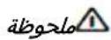
.1. فوهة الشعاع
لَة. فوهة الشعاع
- فوهات الشعاع
.1 .فوهة
.2 مسد تيار الهواء
الزناد .3
.4 زرitors
.1 حامل antibيل
.1ä

natural_image
Black silhouette of a hand giving a thumbs-up gesture (no text or symbols)THANK YOU!
MERCI! DANKE! iGRACIAS!

Register your product and benefit from many advantages.
www.kaercher.com/welcome


Rate your product and tell us your opinion.
natural_image
Icon showing a gear and wrench inside a square frame (no text or symbols)www.kaercher.com/dealersearch
Alfred Kärcher SE & Co. KG
Alfred-Kärcher-Str. 28-40
71364 Winnenden (Germany)
Tel.: +49 7195 14-0
Fax: +49 7195 14-2212