BR 5540 RS Bp Pack - Industrial floor scrubber Kärcher - Free user manual and instructions
Find the device manual for free BR 5540 RS Bp Pack Kärcher in PDF.
User questions about BR 5540 RS Bp Pack Kärcher
0 question about this device. Answer the ones you know or ask your own.
Ask a new question about this device
Download the instructions for your Industrial floor scrubber in PDF format for free! Find your manual BR 5540 RS Bp Pack - Kärcher and take your electronic device back in hand. On this page are published all the documents necessary for the use of your device. BR 5540 RS Bp Pack by Kärcher.
USER MANUAL BR 5540 RS Bp Pack Kärcher
natural_image
Exterior view of a Karcher industrial cleaning machine (no visible text or symbols on the device body)Deutsch 3
English 13
Français 22
Italiano 32
Nederlands 42
Español 52
Português 62
Dansk 72
Norsk 82
Svenska 91
Suomi 101
Ελληνικά 110
Türkçe 121
Русский 130
Magyar 141
Čeština 151
Slovenščina 161
Polski 171
Românește 181
Slovenčina 191
Hrvatski 201
Srpski 211
Български 221
Eesti 232
Latviešu 241
Lietuviškai 251
Українська 261
Register and win! www.kaercher.com/register-and-win

EAC

59663620 05/19
text_image
Technical diagram of a car interior with numbered parts and exploded views, likely for assembly or maintenance purposes.natural_image
Technical line drawing of a vehicle battery pack with multiple circuit connections and mounting brackets (no text or symbols)natural_image
Technical line drawing of a mechanical assembly with a black arrow indicating direction (no text or symbols on the diagram itself)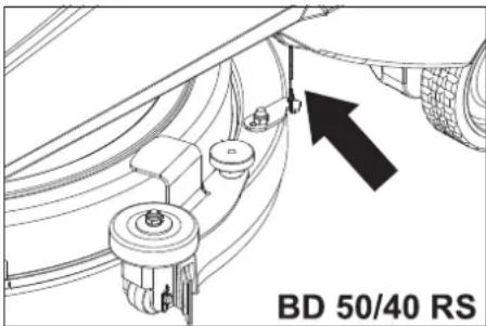
text_image
BD 50/40 RSnatural_image
Technical line drawing of a mechanical device with wheels and a handle (no text or symbols)natural_image
Technical line drawing of a robotic device with internal components and directional arrows (no text or symbols)Befestigungspunkte
Lagerung
△VORSICHT
natural_image
Technical line drawing of a vehicle's internal components, showing engine, motors, and structural parts (no text or labels)text_image
Technical diagram of a mechanical component with numbered parts labeled 1, 2, and 3text_image
Technical diagram of a car engine showing internal components and directional arrows labeled 1 and 2.text_image
Technical diagram showing mechanical assembly with labeled components and directional arrows indicating motion or movement.text_image
Technical diagram of a mechanical assembly with labeled parts 1 and 21 Saugschlauch
2 Kupplung Saugbalken
natural_image
Technical line drawing of a mechanical clamp or bracket assembly (no text or symbols)1 Rändelmutter
text_image
Technical diagram of a curved mechanical component with labeled parts 1 and 2text_image
Technical diagram of a mechanical device with labeled parts 1 and 2
Chairman of the Board of Management

S. Reiser
Director Regulatory Affairs & Certification
71364 Winnenden (Germany)
Tel.: +49 7195 14-0
Fax: +49 7195 14-2212
Winnenden, 2019/05/01
Please read and comply with these original instructions prior
to the initial operation of your appliance and store them for later use or subsequent owners.
Contents
Safety instructions ..... EN 1
Function.....EN 1
Proper use.....EN 1
Environmental Protection, Disposal....EN 1
Operating and Functional Elements....EN 2
Before Commissioning ..... EN 3
Operation.....EN 4
Transport....EN 5
Storage....EN 5
Maintenance and care.....EN 6
Faults.....EN 7
Accessories....EN 8
Specifications ..... EN 9
Accessories and Spare Parts . EN 9
Warranty ...... EN 9
EU Declaration of Conformity . EN 9
Safety instructions
Before using the appliance for the first time, read and observe these operating instructions and the accompanying brochure:
Safety information for brush cleaning units and spray-extraction units, No.
5.956-251.0
The machine has been approved for use on surfaces with gradients of up to 10%.
Behaviour in emergency situations
Press emergency stop button in an emergency. The appliance will be shut off and the park brake will be locked.
Safety Devices
Safety devices serve to protect the user and must not be rendered in operational or their functions bypassed.
Emergency-stop button
To put all functions out of operation immediately: Press emergency-stop button.
Safety pedal
The drive can only be activated when the operated keeps the pedal depressed with the foot.
Hazard levels
DANGER
Pointer to immediate danger, which leads to severe injuries or death.
⚠ WARNING
Pointer to a possibly dangerous situation, which can lead to severe injuries or death.
△CAUTION
Pointer to a possibly dangerous situation, which can lead to minor injuries.
ATTENTION
Pointer to a possibly dangerous situation, which can lead to property damage.
Function
The scrubbing vacuum cleaner is used for the wet cleaning of level floors.
- By selecting a suitable cleaning programme via the programme selection switch, you can easily adapt to the cleaning task at hand.
- A working width of 500mm and a capacity of 38 l of the fresh water tank enable an effective cleaning when the machine is to be used for a longer period of time.
– The appliance is self-driven. - The batteries can be charged using a charger connected to a 230 V socket.
- Battery and charger are included with the packaged units.
Note:
The appliance can be equipped with various accessories depending on the cleaning task.
Please request our catalogue or visit us on the Internet at www.kaercher.com.
Proper use
Use this appliance only as directed in these operating instructions.
- This appliance is suited for the commercial use, e.g. in hotels, schools, hospitals, factories, shops, offices, and rental companies.
- The appliance may only be used for the cleaning of hard surfaces that are not sensitive to moisture and polishing operations.
- The application temperature ranges from +5^ to +40^ .
- The appliance is not suited for the cleaning of frozen grounds (e.g. in cold stores).
- The appliance may only be equipped with original accessories and spare parts.
- The appliance was designed for the cleaning of floors inside or of covered surfaces.
– The appliance is not intended for the cleaning of public traffic routes. - Please consider the allowed load per surface unit of the floor. Details of load per surface unit can be found in the technical data.
- The appliance is not suited for the use in potentially explosive environments.
- The machine should not be used to suck in inflammable gases, undiluted acids or solvents.
This includes petrol, thinning agents or hot oil that can form an explosive mixture when it comes in contact with sucked air. Do not use acetone, undiluted acids and solvents as they are aggressive towards the materials from which the appliance is made.
- Reactive metal dusts (for e.g. aluminium, magnesium, zinc) can form explosive gases when they come in contact with highly alkaline or acidic detergents.
Environmental Protection, Disposal

The packaging materials are recyclable. Please do not throw packaging in the domestic waste but pass it on for recycling.
Old units contain valuable recyclable materials. Batteries, oil and similar substances may not be released into the environment. Therefore please dispose of old units through suitable collection systems.
Notes about the ingredients (REACH)
You will find current information about the ingredients at:
www.kaercher.com/REACH
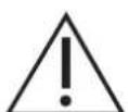
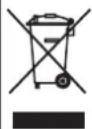
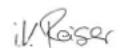
Operating and Functional Elements
text_image
Technical diagram of a car interior with numbered parts and exploded views, likely for maintenance or assembly reference.1 Hose connection, automatic filling
2 Fresh water tank
3 Charge status indicator (only Bp Pack model)
4 waste water tank
5 Float
6 Dirt water discharge hose
7 Appliance plug
8 Battery socket
9 Battery
10 Power plug for charger (only Bp Pack model)
11 Vacuum bar
12 Fresh water valve
13 Fresh water strainer
14 Fresh water tank cover
15 Cleaning head
16 Suction bar support for severe soiling (two-step method)
17 Fresh water level display Drainage hose for fresh water
18 Drive pedal
19 Standing area for operator
20 Safety pedal
21 Lock
22 Operator console
23 Steering wheel
24 Unlock lever, driving
25 Unlock lever, pushing
A Coarse dirt pan (BR model only)
B Spray protection, side (BR model only)
Colour coding
- The operating elements for the cleaning process are yellow.
- The controls for the maintenance and service are light gray.
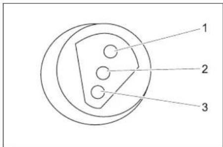
Battery load indicator
text_image
1 2 3| 1 green Illuminated: Charge is completed. |
| 2 yellow Illuminated: Final phase of charging process. |
| 3 red Illuminated: Charging process.Blinking: Initialisation of charger. |
Operator console

text_image
5 6 7 8 9 10 KARCHER® Professional B-42 P/B 4 3 2 11 Program selection switch
2 Key switch
3 Emergency-stop button (turn to release)
4 Driving direction switch, selected driving direction will illuminate
5 Horn
6 Battery display
7 Operating hour counter
8 Fuse for controls
9 Fuse for suction turbine
10 Fuse for brush drive
Battery display
| glows Battery is charged. |
| blinking The battery must be charged,the brush drive and detergentapplication are deactivated. |
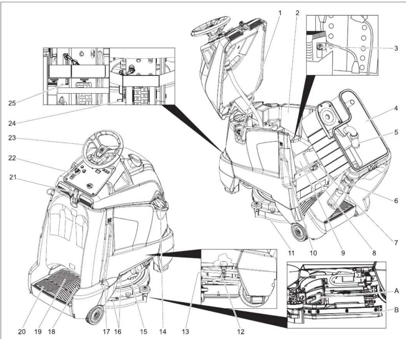
Program selection switch
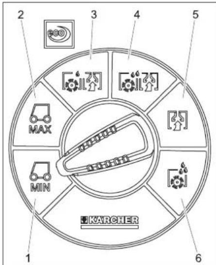
text_image
2 3 4 5 MAX MIN KARCHER 1 61 Driving, limited speed range
2 Driving, maximum speed range
3 Light cleaning intensity (eco)
4 High cleaning intensity
5 Vacuuming
6 Apply detergent solution
Before Commissioning
Install the batteries (only Bp model)
Please observe the following warning notes when handling batteries:
 | Observe the directions on the battery, in the instructions for use and in the vehicle operating instructions |
 | Wear eye protection |
 | Keep children away from acid and batteries |
 | Danger of explosion |
 | Fire, sparks, naked flames and smoking must be strictly avoided |
 | Danger of chemical burns |
 | First aid |
 | Warning note |
 | Disposal |
 | Do not throw the battery into the regular waste |
| Pb |
Pb
⚠️DANGER
Risk of explosion. Do not place tools or the like on the battery, i.e. on the terminal poles and cell connectors.
Risk of injury. Ensure that wounds never come into contact with lead. Always clean your hands after having worked with batteries.
Maximum battery dimensions
| Length Width | Height | |
| 330 mm 172 mm | 236 mm |
If you use wet batteries in the Bp model, then follow the following instructions:
- It is necessary to conform to the maximum battery dimensions.
- The battery cover needs to be opened while charging wet (maintenance-free) batteries.
- While charging wet batteries, follow the specifications of the battery manufacturer.
| Battery set Order No. | |
| 3 x 12V/70 A, maintenance-free (Gel) | 6.654-093.0 |
Insert batteries and connect
The Bp package model contains a built-in battery.
The deep discharge protection of the appliance is set to the respective planned battery type. Therefore, only the battery type mentioned in the following must be in-
stalled into the appliance as new equipment or replacement.
| Device Battery type | |
| 1.533-170.0 mainten | ance-free battery (gel) |
| 1.533-171.0 | |
| 1.533-172.0 | |
| 1.533-173.0 |
→ Open the lock.
→ Swivel the top of the appliance forward.
→ Tilt the waste water tank backwards.
natural_image
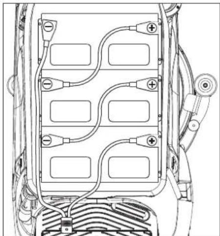
Technical line drawing of a vehicle battery pack with multiple circuit breakers and wiring (no text or symbols)→ Insert the batteries into the appliance.
→ Connect poles with the enclosed connecting cables.
ATTENTION
Risk of damage. Mind correct polarity.
→ Connect the connection cable to the free battery poles (+) and (-).
ATTENTION
The battery can be damaged by deep discharge. Charge the battery before commissioning the machine.
Charging battery
Note:
The appliance is equipped with a total discharge protection, i.e. if the still admissible minimum of the capacity is reached, only vacuuming and driving is possible.
→ Drive the machine directly to the charging station; avoid any steep gradients in the process.
→ Remove the power plug of the appliance from the holder and connect it to the mains supply (model Bp Pack only). Average charging time is approx. 10 hours.
After charging
→ Remove the power plug from the charger and hook the holder into the appliance (model Bp Pack only).
Removing the batteries
→ Open the lock.
→ Swivel the top of the appliance forward.
→ Tilt the waste water tank backwards.
→ Clamp off the minus pole of the battery.
→ Clamp off the remaining cables from the battery.
→ Remove the batteries.
→ Dispose of the used batteries according to the local provisions.
Pushing the device
While standing, the device is protected against rolling off with the help of an electrical immobilising brake. To push the device, you need to first unlock the immobilising brake.
→ Press the unlocking lever down to unlock the parking brake.
⚠️DANGER
Risk of accident if the device rolls away. After completion of the pushing procedure, pull down the unlocking lever and thus reactivate the parking brake.
ATTENTION
Risk of damage. Do not push the device faster than 7 km/h.
Unloading
Note:
Take the foot off the accelerator pedal, press the emergency-stop button and turn the key switch to "0" to immediately deactivate all functions.
→ Remove the cardboard packaging towards the top of the appliance.
→ Put the accompanying cardboard aside.
→ Cut and remove the strap retainer.
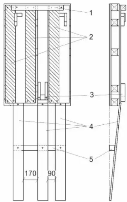
text_image
1 2 3 4 5 170 901 Squared timber, condition on delivery
2 Roll-off ramp, condition on delivery
3 Fixation front wheel
4 Roll-off ramp, after conversion
5 Squared timber, after conversion
→ Unscrew the squared timber and the roll-off ramps from the pallet.
→ Screw down the roll-off ramps and squared timber as shown above.
→ Remove the front wheel lock.
→ Press the unlocking lever down to unlock the parking brake.
→ Push the appliance forward off the pallet.
→ Press the unlocking lever upward to unlock the parking brake.
Operation
⚠ WARNING
Long hours of using the appliance can cause circulation problems in the hands on account of vibrations.
It is not possible to specify a generally valid operation time, since this depends on several factors:
– Proneness to blood circulation deficiencies (cold, numb fingers).
– Low ambient temperature. Wear warm gloves to protect hands.
– A firm grip impedes blood circulation.
– Continuous operation is worse than an operation interrupted by pauses.
In case of regular, long-term operation of the device and in case of repeated occurrence of the symptoms (e.g. cold, numb fingers) please consult a physician.
Note:
Take the foot off the accelerator pedal, press the emergency-stop button and turn the key switch to "0" to immediately deactivate all functions.
→ Carry out maintenance jobs "Prior to operation" (see section "Maintenance and Care").
Check immobilizing brake
DANGER
Risk of accident. Prior to every operation, the parking brake must be checked for proper function on a level ground.
→ Set main switch to "0".
→ Press emergency-stop button.
If the appliance can be moved by hand, the parking brake is not engaged.
→ Pull up the reset lever of the parking break.
If the appliance can still be moved by hand, the parking break is defective. Shut down the appliance and call Customer Service.
Brakes
DANGER
Risk of accident. If the device does not have an adequate braking effect on an incline, press the emergency stop button:
Filling in detergents
Fresh water
→ Close the lid of the fresh water tank.
⚠ WARNING
Observe regulations of water supplier. According to applicable regulations, the appliance must never be used on the drinking water net without a system separator. A suitable system separator by KÄRCHER or alternatively a system separator according to EN 12729 type BA must be used. Water that was flowing through a system separator is considered non-drinkable.
△CAUTION
Always connect the system separator to the water supply, never directly to the appliance!
→ Connect the hose to the automatic filling system and open the water supply (max. 60 °C, max. 5 bars).
→ Monitor the appliance - the automatic filling system will interrupt the water supply when the tank is full.
→ Shut off the water supply and disconnect the hose from the appliance.
or
→ Open the cover of the fresh water reservoir.
→ Fill in fresh water (maximum 60 °C). Leave sufficient space for the detergent.
→ Close the cover of the fresh water reservoir.
Note:
Fill up the fresh water tank completely prior to the initial start-up to bleed the water pipe system.
If the pipe system is empty, it can take up to 2 minutes until the detergent solution exits the cleaning head.
Detergent
⚠ WARNING
Risk of damage. Only use the recommended detergents. With other detergents, the operator bears the increased risk regarding the operational safety and danger of accident.
Only use detergents that are free from solvents, hydrochloric acid and hydrofluoric acid. Follow the safety instructions for using detergents.
Note:
Do not use highly foaming detergents.
Recommended detergents:
| Application Detergent | |
| Routine cleaning of all water resistant floors | RM 780RM 746 |
| Routine cleaning of glossy surfaces (e.g. granite) | RM 755 es |
| Routine cleaning and basic cleaning of industrial floors | RM 69 ASF |
| Routine cleaning and basic cleaning of fine stoneware tiles | RM 753 |
| Routine cleaning of tiles in sanitary areas | RM 751 |
| Cleaning and disinfection in sanitary areas | RM 732 |
| Removal of coating from all alkali-resistant floors (e.g. PVC) | RM 752 |
| Removal of coating from li-noleum floors | RM 754 |
→ Add the detergent to the fresh water reservoir.
text_image
A B C 11 Fresh water valve
A Maximum fresh water volume
B Half of the fresh water volume
C Valve for fresh water closed
→ Turn the valve of the fresh water into the desired position.
Driving
Carry out the initial trials in an open surface so that you familiarise yourself with the appliance.
⚠️DANGER
Danger of tipping if gradient is too high.
→ The gradient in the direction of travel should not exceed 10%.
Danger of tipping when driving round bends at high speed.
Danger of slipping on wet floors.
→ Drive slowly when cornering.
Danger of tipping on unstable ground.
→ Only use the machine on sound surfaces.
Danger of tipping with excessive sideways tilt.
→ The gradient perpendicular to the direction of travel should not exceed 10%.
→ Step on the standing platform.
→ Do not press the accelerator pedal.
→ Release emergency-stop button by turning.
→ Set main switch to "1".
→ Set the speed range on the programme selection switch.
→ Set the drive direction using the drive direction button at the operator console.
Note:
The travel direction switch also serves as a safety switch. Hence, it must be pressed, even if the desired direction of travel has already been selected before.
→ Press the accelerator carefully to drive.
Note:
The direction of travel can also be changed while driving. This way, even heavily soiled spots can be cleaned by driving back and forth several times.
Overload
In case of overloading, the drive motor automatically switches off after a certain period.
→ Allow the appliance to cool down at least for 5 minutes.
Cleaning
Note:
The detergent supply and brush drive are interrupted till further movement if the device stands at one place for more than 2 seconds.
→ Step on the standing platform.
→ Do not press the accelerator pedal.
→ Release emergency-stop button by turning.
→ Set main switch to "1".
→ Turn the program selection switch to the desired cleaning program.
→ Set the forward drive direction using the drive direction button at the operator console.
→ Press accelerator pedal and drive to the surface to be cleaned.
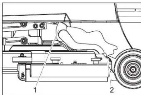
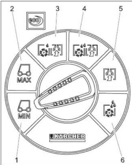
Severe soiling (two-step method)
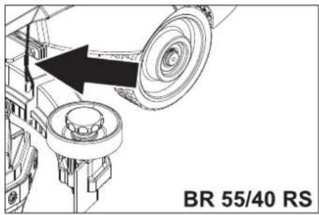
text_image
BR 55/40 RS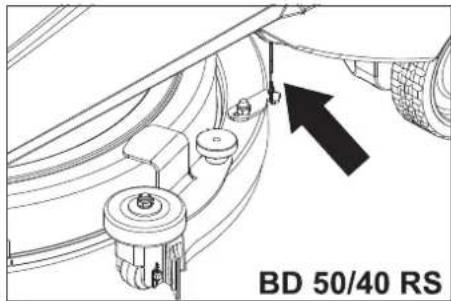
text_image
BD 50/40 RS→ Hook in both ropes on the suction bar so that the suction bar is not lowered.
→ Set programme selection switch to "Apply detergent".
→ Apply detergent solution to the severelyk contaminated surface and let it soak in.
→ Unhook both ropes from the suction bar.
→ Perform the second cleaning run with light or high cleaning intensity.
Complete cleaning
→ Set the program selection switch to suction or vacuuming.
→ Push the appliance a little further to vacuum up the remaining water.
Shutting down
→ Park the machine on an even surface.
→ Turn key to "0" and remove it.
Empty tanks
Drain off dirt water
Note:
Overflow waste water tank. The suction flow is interrupted by a float when the waste water tank is full. Empty the waste water tank.
⚠ WARNING
Please observe the local provisions regarding the wastewater treatment.
→ Take the wastewater discharge hose from the support and open the lid of the drain hose.
→ Press the hose end together and lower it over the disposal unit.
→ Regulate the force of the dirt waster stream by pressing the hose end together.
→ Swivel the top of the appliance forward.
→ Clean the swimmer and check the movement of the swimmer ball.
→ Rinse the waste water tank with clear water.
→ Clean the interior of the top of the appliance.
→ Press the wastewater hose into the holder on the appliance.
Drain off clean water
→ Take the fresh water discharge hose from the support and lower above a suitable collection device.
→ Drain off the detergent liquid.
→ Remove the lid from the fresh water reservoir.
→ Rinse the fresh water reservoir with clear water (max. 60°C).
ATTENTION
Risk of damage for fresh water container, valves and seals. Never leave the cleaning solution in the fresh water reservoir after operation.
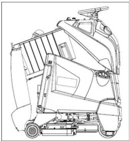
natural_image
Technical line drawing of a mechanical lift or lift assembly (no text or symbols)→ Store the appliance as shown above to dry off the tanks.
Transport
DANGER
Risk of injury! When loading or unloading the machine, it may only be operated on gradients of max. 10%. Drive slowly.
⚠CAUTION
Risk of personal injury or damage! Mind the weight of the appliance during transport.
→ Remove the suction bar and the brush from the appliance.
→ When transporting in vehicles, secure the appliance according to the guidelines from slipping and tipping over.
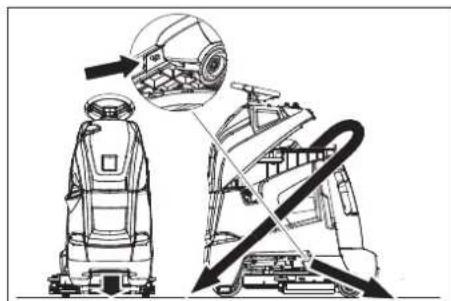
natural_image
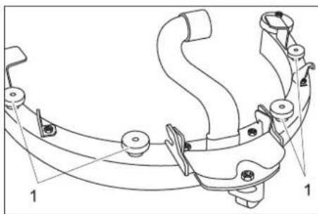
Technical line drawing of a robotic device with internal components and directional arrows indicating motion (no text or symbols)Fastening points
Storage
CAUTION
Risk of personal injury or damage! Consider the weight of the appliance when storing it.
This appliance must only be stored in interior rooms.
Maintenance and care
DANGER
Risk of injury! Before carrying out any tasks on the machine, set the main key to "0" and remove it. Pull the battery plug.
⚠ WARNING
Suction turbine will continue to run for a while after switch-off. Carry out maintenance tasks only after the suction turbine has come to a halt.
→ Drain and dispose of the dirt water and the residual fresh water.
Maintenance schedule
Prior to operation:
→ Check and ensure that the top of the appliance is seated properly on the waste water tank.
→ Check tyre status.
→ Check if brush is fitted properly.
→ Check the inserts of the suction hose for leaks.
→ Check fastening of the suction bar (see "Maintenance tasks").
→ Check the lid of the drain hose for the wastewater tank for tightness.
→ Check the correct positioning of both drain hoses in their holders.
→ Check accelerator pedal, brake and steering wheel for correct functioning
→ Check acid level in wet batteries; refill distilled water, if required.
After operation:
→ Empty the waste water tank.
→ Rinse the waste water tank with clear water.
→ Clean the sieve and the swimmer in the waste water tank (see "Maintenance tasks").
→ Clean fresh water tank.
→ Switch on the suction for drying the system.
→ Empty and clean the coarse dirt pan (BR model only).
→ Check brush for wear and tear and clean it.
→ Clean vacuum lips in the vacuum bar and check for wear.
→ Clean the outside of the appliance with a damp cloth which has been soaked in mild detergent.
→ Check device externally for damage.
→ Store the appliance as shown above to dry off the tanks (see "Empty tanks").
→ Charge the battery:
If the charging state of the battery is under 50%, charge the battery fully and without interruption.
If the charging state of the battery is over 50%, only recharge the battery if the entire operation duration will be required when next used.
Weekly
→ When used regularly, charge the battery fully and without interruption at least once a week.
Every 50 operating hours
→ Clean upper side of the batteries.
→ Check acid density in wet batteries.
→ Check battery cable for correct positioning.
→ Clean the sieve in the fresh water reservoir.
BR 55/40 RS only:
→ Check the side spray protection on the cleaning head.
Monthly
→ For long periods of disuse, only turn the device off when the battery is fully charged. Fully recharge the battery at least every month.
Every 100 operating hours
→ Clean battery room and battery casing.
Every 200 operating hours
→ Check immobilising brake. *
→ Clean the joints on the cleaning head hookup.
→ Check carbon brushes and commutators of all motors for wear and tear. *
→ Check tension of steering chain. *
→ Check the tension of the drive chains on the drive. *
* To be done by Customer Service.
Maintenance contract
To ensure a reliable operation of the appliance maintenance contracts can be concluded with the competent Kärcher sales office.
Maintenance BR 55/40 RS
Dismantling the vacuum bar
→ Pull out the suction hose from the vacuum bar.
natural_image
Technical line drawing of a mechanical assembly with no visible text or symbols→ Raise the handle of the suction bar coupling.
→ Remove the vacuum bar.
Turn or replace vacuum lips
→ Remove the vacuum bar.
text_image
Technical diagram of a mechanical component with numbered parts labeled 1, 2, and 3.1 Star handle
2 Plastic part
3 Vacuum lip
→ Unscrew the star grips.
→ Remove the plastic parts.
→ Remove the vacuum lips.
→ Turn the vacuum lips or insert new ones.
→ Insert the plastic parts.
→ Screw in and tighten the star grips.
Replacing the brush rollers
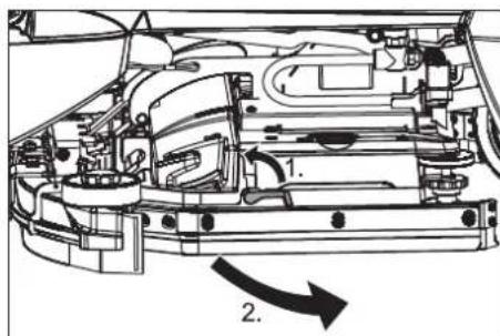
text_image
Technical diagram of a car engine showing internal components and directional arrows labeled 1 and 2.→ Swivel the unlocking lever upward.
→ Swivel the spray protection toward the front.
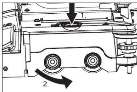
text_image
Technical diagram showing mechanical assembly with labeled components and directional arrows indicating motion or movement.→ Press the brush change key and tilt the cover on the brush head towards the side.
→ Pull out the brush rollers.
→ Insert and lock into place the new brush rollers.
→ Close the cover, align the brushes and lock in the cover.
→ Swivel the spray guard back.
→ Swivel the unlocking lever downward.
Maintenance tasks BD 50/40 RS
Dismantling the vacuum bar
→ Set programme selection to "Drive".
→ Turn key to "0" and remove it.
→ Pull out the suction hose from the vacuum bar.
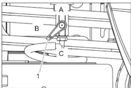
text_image
Technical diagram of a vehicle's internal components with numbered parts labeled 1 and 21 Suction hose
2 Suction bar coupling
→ Pull out the suction hose from the vacuum bar.
→ Loosen the suction bar coupling.
→ Remove the vacuum bar.
Replace or turn vacuum lips
→ Dismantle the vacuum bar.
natural_image
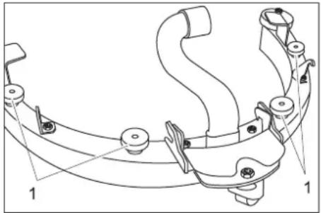
Technical line drawing of a mechanical clamp or bracket assembly (no text or symbols)1 Lock nut
→ Unscrew the knurled nuts.
→ Remove the suction bar insert from the bottom of the suction bar.

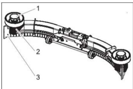
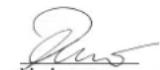
text_image
Technical diagram of a curved mechanical component with labeled parts 1 and 21 Vacuum lip
2 Suction bar insert
→ Remove the vacuum lips from the suction bar insert.
Note:
The vacuum lip can be turned around 3 times until all edges are worn. Then a new vacuum lip is required.
→ Reverse the suction lip or replace it and rehook it into the hooks of the suction bar insert.
→ Place the suction bar insert into the suction bar.
→ Screw on the knurled nuts and tighten them.
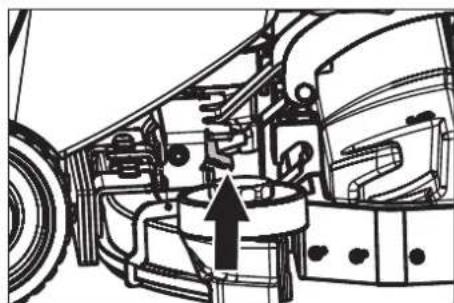
Replacing the disk brushes
→ Lift the cleaning head.
→ Turn key to "0" and remove it.
→ Turn the unlocking lever of the sliding brush in an anti-clockwise direction - the brushes will fall downward and can be pulled outward at the bottom of the device.
→ Hold the new brush under the cleaning head.
→ Turn the unlocking lever of the sliding brush in clockwise direction and press the brush upward.
→ Release the unlocking lever and check that the brush is sitting properly.
Maintenance tasks - all types
Cleaning the floater
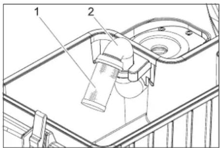
text_image
Technical diagram showing a mechanical assembly with labeled parts 1 and 2, likely illustrating a component or assembly.1 Sieve with floater ball 2 Pipe
→ Clean the sieve from the outside and rinse it.
→ Check the mobility of the floater ball.
→ Hold the pipe firmly and pull out the sieve from the pipe.
→ Clean sieve and ball.
→ Hold the pipe firmly and reinsert the sieve.
If it is too dirty:
Frost protection
In case of danger of frost:
→ Empty the fresh and waste water tank.
→ Store the appliance in a frost-protected room.
Faults
DANGER
Risk of injury! Before carrying out any tasks on the machine, set the main key to "0" and remove it. Pull the battery plug.
⚠ WARNING
Suction turbine will continue to run for a while after switch-off. Carry out maintenance tasks only after the suction turbine has come to a halt.
In case of faults that cannot be remedied using the table below please contact the customer service.
Errors shown by the battery indicator
| A blinking battery display indicates the following faults. The time sequence of the fault. | ||
| Number of flashes Fault Remedy | ||
| 1 Battery discharged oder battery cable damaged. Check battery cable, charge battery. | ||
| 2 Cable to drive motor interrupted. Inform Customer Service. | ||
| 3 Cable to drive motor shorted. | ||
| 4 Deep discharge power not reached Charge battery. | ||
| 5 | - | - |
| 6 Drive attempt while charger is connected (Bp Pack model only). | Remove the power plug from the charger and hook the holder into the appliance (model Bp Pack only). | |
| 7 Fault in drive pedal. Release the drive pedal prior to turning on the appliance. | ||
| 8 Control faulty. Inform Customer Service. | ||
| 9 Parking brake fault. | ||
| 10 Shorted connection on battery connection. Check the terminal is on the batteries. | ||
| Once every 5 seconds | Control idle. | Turn the main switch to "0" and turn it back to "1". |
Errors shown by the charge status indicator (only Bp Pack model)
| Blinking signal | Fault Remedy | |
| Blinks red | Battery poled or is not connected | Check battery cable for correct sitting. |
| Blinks green and yellow. | Cable connection between battery and charger is poor. | Check battery cable for correct sitting.Check whether the connection to the battery was interrupted during the charge process. |
| Battery defective | Check battery. |
→ Before restarting the charger, pull the plug out of the socket, wait until the
charge status indicator shuts off and plug the mains plug back in.
Faults
| Fault Remedy By whom | ||
| Appliance cannot be started Insert | the battery plug on the device. Operator | |
| Swivel the top of the appliance down and close the lock. Operator | ||
| Release emergency-stop button by turning. Operator | ||
| Check battery cable for correct sitting. Operator | ||
| Check battery cable for corrosion; clean, if required. Operator | ||
| Battery capacity exhausted; recharge battery. Operator | ||
| Remove the power plug from the charger and hook the holder into the appliance (mode Bp Pack only). | Operator | |
| Device does not drive or drives only slowly | Release accelerator pedal, turn the key switch to "0", turn the key switch to "1", press the accelerator pedal. | Operator |
| Reset fuse of control system. Operator | ||
| Set the unlock lever to "drive". Operator | ||
| Charge battery. Operator | ||
| Motor or control overheated; switch off the appliance and let it cool down for 5 minutes. | Operator | |
| Remove obstacles from the wheels or push the appliance away from the obstacle. Operator | ||
| Device does not brake | Park brake deactivated; pull the unlock lever down to activate. | Operator |
| No or inadequate suction power | Empty the waste water tank. | Operator |
| Reset fuse of suction turbine. | Operator | |
| Foam generated in waste water tank? Use less or a different detergent. Use defoamer. | Operator | |
| Clean the seals between waste water tank and top of the appliance and check for leaks replace if required. | Operator | |
| Clean the vacuum lips on the vacuum bar, turn or replace if required. | Operator | |
| Check suction hose for blockages; clean if required. Operator | ||
| Check connection between suction hose and suction bar and suction hose and waste-water tank. | Operator | |
| Check the suction hose for tightness; replace if required. | Operator | |
| Check if the cover on the dirt water discharge hose is closed | Operator | |
| Clean the floater in the waste water tank. | Operator | |
| The battery indicator blinks | Charge battery. Operator | |
| See "Faults with display". | Operator | |
| Insufficient cleaning result | Select a more intensive cleaning program. | Operator |
| Check the brushes for wear, replace if required. | Operator | |
| Check brush for contamination and clean it. | Operator | |
| Check whether the detergent and the brush are suitable for the cleaning task. | Operator | |
| Charge battery. Operator | ||
| Brushes do not turn | Reset fuse of brush drive. | Operator |
| Check the brush for blockage by foreign objects; remove the foreign objects. | Operator | |
| Charge battery. Operator | ||
| No or very little detergent solution gets added | Check level of detergent solution in the fresh water tank; refill, if required. | Operator |
| Open fresh water valve. | Operator | |
| Select a more intensive cleaning program. | Operator | |
| Check fresh water sieve; clean if required. | Operator | |
| The cleaning head is not lowered. | Reset fuse of control system. Operator | |
| The suction bar is not lowered. | Unhook the ropes from the suction bar. | Operator |
Accessories
| Description | Part no.: | Description | Piece | Machine requires piece |
| Battery * | 6.654-093.0 | 12V/70 Ah, maintenance-free (gel), | 1 | 3 |
| Dosing station | 2.641-811.0 | To fill the appliance with water and detergent. | 1 | 1 |
| * Only suited for appliances with maintenance-free batteries (gel). | ||||
Accessories BR 55/40 RS
| Description | Part no.: | Description | Piece | Machine requires piece |
| Brush roller, white (soft) | 4.762-409.0 | For cleaning slightly dirtied or sensitive floors. | 1 | 2 |
| Brush roller, red (medium, standard) | 4.762-393.0 | For all floors. | 1 | 2 |
| Brush roller, hard (green) | 4.762-411.0 | Hard, for severe contamination and basic cleaning; only suitable for insensitive floor coverings. | 1 | 2 |
| Brush roller, black (very hard) | 4.777-412.0 | Very hard, for extreme contamination and basic cleaning; only suitable for insensitive floor coverings. | 1 | 2 |
| Description | Part no.: | Description | Piece | Machine requires piece |
| Brush roller, high/low (medium hardness) | 4.762-410.0 M | Medium hardness, to clean structured floors and deeper grouts. | 1 | 2 |
| Pad roller shaft 4.762-415.0 For intake of roller pads. | of roller pads. | 1 2 | ||
| Pad, soft, yellow 6.369-732.0 For polishing floors. | 1 2 | |||
| Pad, medium soft, red 6.369-734.0 For cleaning slightly dirtied floors. | 1 2 | |||
| Pad, hard, green 6.369-733.0 For cleaning normal to heavily dirtied floors. | 1 2 | |||
| Rubber lips of vacuum bar 6.273-294.0 1 set 1 set |
Accessories BD 50/40 RS
| Description | Part no.: | Description | Piece | Machine requires piece |
| Disk brush, blue (medium, standard) | 8.600-042.0 | For cleaning slightly dirtied or sensitive floors. | 1 | 1 |
| Disk brush, grey (hard) | 8.600-043.0 | For cleaning heavily dirtied floors. | 1 | 1 |
| Driver plate | 8.600-041.0 | For intake of pads. | 1 | 1 |
| Rubber lips of vacuum bar 8.634-020.0 | 1 set 1 set |
Specifications
| BR55/40RS | BD50/40RS | ||
| Power | |||
| Nominal voltage | V | 36 | |
| Battery capacity (Pack model) | Ah(5h) | 70 | |
| Average power consumption | W | 1480 | 1080 |
| Drive motor output (rated output) | W | 157 | |
| Suction engine output | W | 470 | |
| Brush engine output | W | 600 | 209 |
| Vacuuming | |||
| Cleaning power, air quantity | l/s | 34 | |
| Cleaning power, negative pressure | kPa | 11,7 | |
| Cleaning brushes | |||
| Working width | mm | 559 | 508 |
| Brush diameter | mm | 96 | 508 |
| Brush speed | 1/min | 1500 | 180 |
| Dimensions and weights | |||
| Detergent application | l/min | 1,25 | |
| Drive speed (max.) | km/h | 4,3 | |
| Climbing capability (max.) | % | 10 | |
| Theoretical surface cleaning performance | m2/h | 2350 | 1840 |
| Fresh/waste water tank volume | l | 38/38 | |
| Length | mm | 1118 | |
| Width | mm | 744 | 691 |
| Height mm 1316 | |||
| Permissible overall weight | kg 330 | ||
| Transport weight | kg | 275 | 255 |
| Surface load | kPa | 2190 | |
| Values determined as per EN 60335-2-72 | |||
| Vibration total value on arms | m/s2 | 3,6 | |
| Vibration total value on feet | m/s2 | <2,5 | |
| Uncertainty K | m/s2 | 1 |
| Sound pressure level L_pA | dB(A) | 60 |
| Uncertainty K_pA | dB(A) | 6 |
| Sound power level L_WA + Uncertainty K_WA | dB(A) | 79 |
| Charger (only Bp Pack model) | ||
| Nominal voltage | V | 85...264 |
| Frequency | Hz | 50/60 |
| Current pickup, max. A | 15 | |
| Type of protection | IP66 | |
| Humidity, max. | % | 90 |
| Ambient temperature | °C | +5...+45 |
Accessories and Spare Parts
Only use original accessories and spare parts, they ensure the safe and trouble-free operation of the device.
For information about accessories and spare parts, please visit www.kaercher.com.
Warranty
The warranty terms published by the relevant sales company are applicable in each country. We will repair potential failures of your appliance within the warranty period free of charge, provided that such failure is caused by faulty material or defects in manufacturing. In the event of a warranty claim please contact your dealer or the nearest authorized Customer Service centre. Please submit the proof of purchase.
EU Declaration of Conformity
We hereby declare that the machine described below complies with the relevant basic safety and health requirements of the EU Directives, both in its basic design and construction as well as in the version put into circulation by us. This declaration shall cease to be valid if the machine is modified without our prior approval.
Product: Floor cleaner
Type: 1.006-xxx
Type: 1.002-xxx
Relevant EU Directives
2006/42/EC (+2009/127/EC)
2014/30/EU
Applied harmonized standards
EN 55014-1: 2006+A1: 2009+A2: 2011
EN 55014-2: 2015
EN 60335-1
EN 60335-2-29: 2004+A2: 2010
EN 60335-2-72
EN 61000-3-2: 2014
EN 61000-3-3: 2013
EN 62233: 2008
Applied national standards
The signatories act on behalf of and with the authority of the company management.
Chairman of the Board of Management
S. Reiser
Director Regulatory Affairs & Certification
Documentation supervisor:
S. Reiser
Alfred Kärcher SE & Co. KG
71364 Winnenden (Germany)
Tel.: +49 7195 14-0
Fax: +49 7195 14-2212
Winnenden, 2019/05/01
Entreposage .... FR 6
www.kaercher.com/REACH
text_image
Technical diagram of a car interior with numbered components and exploded views, likely for maintenance or assembly reference.natural_image
Technical line drawing of an electronic device chassis with multiple battery cells and wiring (no text or symbols)natural_image
Technical line drawing of a mechanical device with wheels and a handle (no text or symbols)natural_image
Technical line drawing of a robotic device with internal components and directional arrows indicating motion (no text or symbols)Points de fixation
Entreposage
⚠ PRÉCAUTION
natural_image
Technical line drawing of a mechanical assembly with no visible text or symbolstext_image
Technical diagram of a curved mechanical component with numbered parts labeled 1, 2, and 3.text_image
Technical diagram of a car engine showing internal components and directional arrows labeled 1 and 2.text_image
Technical diagram showing mechanical components with numbered annotations and directional arrows indicating motion or movement.text_image
Technical diagram of a mechanical assembly with labeled parts 1 and 2natural_image
Technical line drawing of a mechanical clamp or bracket assembly (no text or symbols)1 Ecrou moleté
text_image
Technical diagram of a curved mechanical component with numbered parts labeled 1, 2, and 3.text_image
Technical diagram of a mechanical device with labeled parts 1 and 22006/42/CE (+2009/127/CE)
2014/30/UE

Chairman of the Board of Management

S. Reiser
Director Regulatory Affairs & Certification
71364 Winnenden (Germany)
Tel.: +49 7195 14-0
Fax: +49 7195 14-2212
Winnenden, 2019/05/01

www.kaercher.com/REACH
text_image
Technical diagram of a car interior with numbered parts and exploded views, likely for maintenance or assembly reference.natural_image
Technical line drawing of an electronic device chassis with multiple battery cells and wiring (no text or symbols)natural_image
Technical line drawing of a mechanical device with wheels and a handle (no text or symbols)natural_image
Technical line drawing of a robotic device with internal components and directional arrows indicating motion (no text or symbols)Punti di fissaggio
Supporto
⚠ PRUDENZA
natural_image
Technical line drawing of a vehicle's internal components, showing engine, motors, and structural parts (no text or labels)text_image
Technical diagram of a curved mechanical component with numbered parts labeled 1, 2, and 3.1 manopola a crociera
2 Parte di plastica
text_image
Technical diagram of a car engine showing internal components and directional arrows labeled 1 and 2.text_image
Technical diagram showing mechanical assembly with labeled components and directional arrows indicating motion or movement.text_image
Technical diagram of a vehicle chassis with labeled parts 1 and 2natural_image
Technical line drawing of a mechanical clamp or bracket assembly (no text or symbols)1 Dado zigrinato
text_image
Technical diagram of a curved mechanical component with labeled parts 1 and 2text_image
Technical diagram showing a mechanical device with labeled parts 1 and 2, likely illustrating a component or assembly.2006/42/CE (+2009/127/CE)
2014/30/UE
71364 Winnenden (Germany)
Tel.: +49 7195 14-0
Fax: +49 7195 14-2212
Winnenden, 2019/05/01

Accessoires ....NL 9
www.kaercher.com/REACH
text_image
Technical diagram of a car interior with numbered parts and exploded views, likely for maintenance or assembly reference.Programmakeuzeschakelaar
text_image
2 3 4 5 MAX MIN 1 6 KARCHERnatural_image
Technical line drawing of an electronic device chassis with multiple connectors and wiring (no text or symbols)natural_image
Technical line drawing of a mechanical assembly with a black arrow indicating direction (no text or symbols on the diagram itself)
text_image
BD 50/40 RSnatural_image
Technical line drawing of a mechanical device with no visible text or symbolsnatural_image
Technical line drawing of a robotic device with internal components and directional arrows indicating motion (no text or symbols)Bevestigingspunten
Opslag
⚠VOORZICHTIG
natural_image
Technical line drawing of a vehicle's internal components, showing engine, motors, and structural parts (no text or labels)text_image
Technical diagram of a curved mechanical component with numbered parts labeled 1, 2, and 3.text_image
Technical diagram of a car engine showing internal components and directional arrows labeled 1 and 2.text_image
Technical diagram showing mechanical assembly with labeled components and directional arrows indicating motion or movement.text_image
Technical diagram of a mechanical assembly with labeled parts 1 and 2natural_image
Technical line drawing of a mechanical clamp or bracket assembly (no text or symbols)1 Kartelmoer
text_image
Technical diagram of a curved mechanical component with labeled parts 1 and 2text_image
Technical diagram of a mechanical device with labeled components 1 and 2
Chairman of the Board of Management

S. Reiser
Director Regulatory Affairs & Certification
71364 Winnenden (Germany)
Tel.: +49 7195 14-0
Fax: +49 7195 14-2212
Winnenden, 2019/05/01
www.kaercher.com/REACH
text_image
Technical diagram of a car interior with numbered parts and exploded views, likely for maintenance or assembly reference.natural_image
Technical line drawing of an electronic device rear panel with wiring and connectors (no text or symbols)natural_image
Technical line drawing of a mechanical lift or lift assembly (no text or symbols)natural_image
Technical line drawing of a robotic device with internal components and directional arrows indicating motion (no text or symbols)Puntos de fijación
Almacenamiento
△PRECAUCIÓN
natural_image
Technical diagram of a vehicle's internal components, showing engine, motors, and structural parts without any text or labels.text_image
Technical diagram of a curved mechanical component with numbered parts labeled 1, 2, and 3.1 mango en estrella
2 Pieza de plástico
text_image
Technical diagram of a car engine showing internal components and directional arrows labeled 1 and 2.text_image
Technical diagram showing mechanical assembly with labeled components and directional arrows indicating motion or movement.text_image
Technical diagram of a mechanical assembly with labeled parts 1 and 2natural_image
Technical line drawing of a mechanical clamp or bracket assembly (no text or symbols)1 tuerca moleteada
text_image
Technical diagram of a curved mechanical component with numbered parts labeled 1, 2, and 3.text_image
Technical diagram of a fire extinguisher system with labeled components2006/42/CE (+2009/127/CE)
2014/30/UE
71364 Winnenden (Germany)
Tel.: +49 7195 14-0
Fax: +49 7195 14-2212
Winnenden, 2019/05/01

Leia o manual de manual original antes de utilizar o seu apare-
www.kaercher.com/REACH
Elementos de comando e de funcionamento

text_image
Technical diagram of a car interior with numbered parts and exploded views, likely for maintenance or assembly reference.natural_image
Technical line drawing of an electronic device chassis with multiple battery and power connections (no text or symbols)Desmontar as baterias
natural_image
Technical line drawing of a mechanical device with wheels and a sensor (no text or symbols)natural_image
Technical line drawing of a robotic device with internal components and directional arrows indicating motion (no text or symbols)Pontos de fixação
Armazenamento
△CUIDADO
natural_image
Technical line drawing of a mechanical assembly with no visible text or symbolstext_image
Technical diagram of a curved mechanical component with numbered parts labeled 1, 2, and 3.1 Punho estrelado
2 Peça em plástico
text_image
Technical diagram of a car engine showing internal components and directional arrows labeled 1 and 2.text_image
Technical diagram showing mechanical assembly with labeled components and directional arrows indicating motion or movement.text_image
Technical diagram of a mechanical assembly with labeled parts 1 and 2natural_image
Technical line drawing of a mechanical clamp or bracket assembly (no text or symbols)1 Porca recartilhada
text_image
Technical diagram of a curved mechanical component with numbered parts labeled 1, 2, and 3.text_image
Technical diagram showing a fire extinguisher system with labeled components 1 and 22006/42/CE (+2009/127/CE)
2014/30/UE

Chairman of the Board of Management

S. Reiser
Director Regulatory Affairs & Certification
71364 Winnenden (Germany)
Tel.: +49 7195 14-0
Fax: +49 7195 14-2212
Winnenden, 2019/05/01

www.kaercher.com/REACH
text_image
Technical diagram of a car interior with numbered parts and exploded views, likely for maintenance or assembly reference.natural_image
Technical line drawing of a vehicle battery pack with multiple circuit connections and mounting points (no text or symbols)natural_image
Technical line drawing of a mechanical device with no visible text or symbolsnatural_image
Technical line drawing of a robotic device with internal components and directional arrows indicating assembly (no text or symbols)Fastgørelsespunkter
Opbevaring
⚠ FORSIGTIG
natural_image
Technical line drawing of a mechanical assembly with no visible text or symbolstext_image
Technical diagram of a mechanical component with numbered parts labeled 1, 2, and 31 Stjernegreb
2 Kunststofdel
3 Sugelæbe
text_image
Technical diagram of a car engine showing internal components and a directional arrow indicating movement or force.text_image
Technical diagram of a vehicle's internal components with numbered parts labeled 1 and 21 Sugeslange
2 Kobling sugebjælke
natural_image
Technical line drawing of a mechanical clamp or bracket assembly (no text or symbols)1 Fingermøtrik
text_image
Technical diagram of a curved mechanical component with labeled parts 1 and 2text_image
Technical diagram showing a spray gun system with labeled components 1 and 22006/42/EF (+2009/127/EF)
2014/30/EU
Chairman of the Board of Management

S. Reiser
Director Regulatory Affairs & Certification
71364 Winnenden (Germany)
Tel.: +49 7195 14-0
Fax: +49 7195 14-2212
Winnenden, 2019/05/01
www.kaercher.com/REACH
text_image
Technical diagram of a car interior with numbered parts and exploded views, likely for maintenance or assembly reference.1 Slangetilkobling, fyllingsautomatikk
2 Rentvannstank
3 Ladetilstandsindikator (kun varianter Bp Pack)
4 Spillvannstank
5 Flottør
6 Avløpsslange spillvann
7 Apparatstøpsel
8 Batterikontakt
9 Batteri
10 Strømstøpsel ladeapparat (kun varianter Bp Pack)
11 Sugebom
12 Ventil rentvann
13 Sil rentvann
14 Deksel friskvanntank
15 Rengjøringshode
16 Sugebomopheng for sterk tilsmussing (to-trinns metode)
17 Nivåanvisning rentvann Avløpsslange friskvann
18 Kjørepedal
19 Staflate for bruker
20 Sikkerhetspedal
21 Lâs
22 Betjeningspanel
23 Ratt
natural_image
Technical line drawing of a vehicle battery pack with multiple circuit breakers and wiring (no text or symbols)natural_image
Technical line drawing of a mechanical lift or lift assembly (no text or symbols)natural_image
Technical line drawing of a robotic device with internal components and directional arrows indicating motion (no text or symbols)Festepunkter
Lagring
⚠FORSIKTIG
natural_image
Technical diagram of a vehicle's internal components, showing engine, motors, and structural parts without any text or labels.text_image
Technical diagram of a mechanical component with numbered parts labeled 1, 2, and 31 Stjernehåndtak
2 Plastdel
3 Sugelippe
text_image
Technical diagram of a car engine showing internal components and directional arrows indicating flow or movement.text_image
Technical diagram showing mechanical assembly with labeled components and directional arrows indicating motion or movement.Vedlikehold (BD 50/40 RS)
Demontere sugebom
text_image
Technical diagram of a mechanical assembly with labeled parts 1 and 21 Sugeslange
2 Kobling sugebom
→ Ta sugeslangen av sugebommen.
→ Løsne kobling sugebom.
→ Ta av sugebommen.
Skift eller snu sugeleppe
→ Demonter sugebom.
natural_image
Technical line drawing of a mechanical clamp or bracket assembly (no text or symbols)1 Fingermutter
text_image
Technical diagram of a curved mechanical component with numbered parts labeled 1 and 21 Sugelippe
2 Sugebominnsats
text_image
Technical diagram of a mechanical device with labeled components 1 and 22006/42/EF (+2009/127/EF)
2014/30/EU

Chairman of the Board of Management

Director Regulatory Affairs & Certification
71364 Winnenden (Germany)
Tel.: +49 7195 14-0
Fax: +49 7195 14-2212
Winnenden, 2019/05/01

www.kaercher.com/REACH
text_image
Technical diagram of a car interior with numbered parts and exploded views, likely for maintenance or assembly reference.natural_image
Technical line drawing of a vehicle chassis with wiring and mounting brackets (no text or symbols)natural_image
Technical line drawing of a mechanical lift or lift assembly (no text or symbols)natural_image
Technical line drawing of a robotic device with internal components and directional arrows indicating motion (no text or symbols)Fästpunkter
Förvaring
⚠FÖRSIKTIGHET
natural_image
Technical diagram of a vehicle's internal components, showing engine, motors, and structural parts without any text or labels.text_image
Technical diagram of a curved mechanical component with numbered parts labeled 1, 2, and 3.1 Stjärnratt
2 Plastdel
3 Sugläpp
text_image
Technical diagram of a car engine showing internal components and directional arrows labeled 1 and 2.text_image
Technical diagram showing mechanical assembly with labeled components and directional arrows indicating motion or movement.text_image
Technical diagram of a mechanical assembly with labeled parts 1 and 21 Sugslang
2 Koppling sugskena
natural_image
Technical line drawing of a mechanical clamp or bracket assembly (no text or symbols)1 Räfflade muttrar
text_image
Technical diagram of a curved mechanical component with labeled parts 1 and 2text_image
Technical diagram showing a mechanical assembly with labeled parts 1 and 2, likely illustrating a valve or pump mechanism.71364 Winnenden (Germany)
Tel.: +49 7195 14-0
Fax: +49 7195 14-2212
Winnenden, 2019/05/01
Sisällysluettelo
www.kaercher.com/REACH
text_image
Technical diagram of a car interior with numbered components and exploded views, likely for maintenance or assembly reference.natural_image
Technical line drawing of a vehicle chassis with battery pack and wiring (no text or symbols)natural_image
Technical line drawing of a mechanical device with wheels and mounting bracket (no text or symbols)natural_image
Technical line drawing of a robotic device with internal components and directional arrows indicating assembly (no text or symbols)Kiinnityspisteet
Säilytys
△VARO
natural_image
Technical line drawing of a mechanical assembly with no visible text or symbolstext_image
Technical diagram of a curved mechanical component with numbered parts labeled 1, 2, and 3.1 Tähtikahva
2 Muoviosa
3 Imuhuuli
text_image
Technical diagram of a car engine showing internal components and directional arrows labeled 1 and 2.text_image
Technical diagram showing mechanical assembly with labeled components and directional arrows indicating motion or movement.text_image
Technical diagram of a mechanical assembly with labeled parts 1 and 21 Imuletku
2 Imupalkin kytkin
natural_image
Technical line drawing of a mechanical clamp or bracket assembly (no text or symbols)1 Pyälletty mutteri
text_image
Technical diagram of a curved mechanical component with labeled parts 1 and 2text_image
Technical diagram showing a mechanical assembly with labeled parts 1 and 2, likely illustrating a component or assembly.
Chairman of the Board of Management
S. Reiser
Director Regulatory Affairs & Certification
71364 Winnenden (Germany)
Tel.: +49 7195 14-0
Fax: +49 7195 14-2212
Winnenden, 2019/05/01
www.kaercher.com/REACH
text_image
Technical diagram of a car interior with numbered components and exploded views, likely for maintenance or assembly reference.natural_image
Technical line drawing of an electronic device chassis with multiple battery cells and wiring (no text or symbols)natural_image
Technical line drawing of a mechanical device with no visible text or symbolsnatural_image
Technical line drawing of a robotic device with internal components and directional arrows indicating motion (no text or symbols)Σημεία στερέωσης
Αποθήκευση
ΔΠΡΟΣΟΧΗ
natural_image
Technical line drawing of a mechanical assembly with no visible text or symbolstext_image
Technical diagram of a mechanical component with numbered parts labeled 1, 2, and 3.text_image
Technical diagram of a vehicle engine showing internal components and directional arrow indicating motion or forcetext_image
Technical diagram showing mechanical assembly with labeled components and directional arrows indicating motion or movement.text_image
Technical diagram of a mechanical assembly with labeled parts 1 and 2natural_image
Technical line drawing of a mechanical clamp or bracket assembly (no text or symbols)text_image
Technical diagram of a curved mechanical component with labeled parts 1 and 2text_image
Technical diagram of a mechanical device with labeled components 1 and 2
Chairman of the Board of Management

S. Reiser
Director Regulatory Affairs & Certification
71364 Winnenden (Germany)
Tel.: +49 7195 14-0
Fax: +49 7195 14-2212
Winnenden, 2019/05/01

www.kaercher.com/REACH
text_image
Technical diagram of a car interior with numbered components and exploded views, likely for maintenance or assembly reference.natural_image
Technical line drawing of a vehicle chassis with battery, wiring, and mounting brackets (no text or symbols)natural_image
Technical line drawing of a mechanical lift or lift assembly (no text or symbols)natural_image
Technical line drawing of a robotic device with internal components and an arrow indicating motion (no text or symbols)Sabitleme noktaları
Depolama
TEDBIR
natural_image
Technical line drawing of a mechanical assembly with no visible text or symbolstext_image
Technical diagram of a curved mechanical component with numbered parts labeled 1, 2, and 3.1 Yıldız kol
2 Plastik parça
3 Emme dudağı
text_image
Technical diagram of a car engine showing internal components and directional arrows labeled 1 and 2.text_image
Technical diagram showing mechanical assembly with labeled components and directional arrows indicating motion or force directions.text_image
Technical diagram of a mechanical assembly with labeled parts 1 and 21 Emme hortumu
2 Emme kolu kavraması
natural_image
Technical line drawing of a mechanical clamp or bracket assembly (no text or symbols)1 Tirtilli somun
text_image
Technical diagram of a curved mechanical component with labeled parts 1 and 21 Emme dudağı
2 Emme kolu adaptörü
text_image
Technical diagram showing a mechanical assembly with labeled parts 1 and 2, likely illustrating a valve or pump mechanism.
Chairman of the Board of Management
Director Regulatory Affairs & Certification
71364 Winnenden (Germany)
Tel.: +49 7195 14-0
Fax: +49 7195 14-2212
Winnenden, 2019/05/01
www.kaercher.com/REACH

text_image
Technical diagram of a car interior with numbered parts and exploded views, likely for maintenance or assembly reference.natural_image
Technical line drawing of a vehicle battery pack with multiple circuit breakers and wiring (no text or symbols)natural_image
Technical line drawing of a mechanical device with no visible text or symbolsnatural_image
Technical line drawing of a robotic device with internal components and directional arrows indicating motion (no text or symbols)Точки крепления
Хранение
△ОСТОРОЖНО
natural_image
Technical line drawing of a mechanical assembly with no visible text or symbolstext_image
Technical diagram of a mechanical component with numbered parts labeled 1, 2, and 3.text_image
Technical diagram of a car engine showing internal components and directional arrow indicating motion or flowtext_image
Technical diagram showing mechanical assembly with labeled components and directional arrows indicating motion or movement.text_image
Technical diagram of a mechanical assembly with labeled parts 1 and 2natural_image
Technical line drawing of a mechanical clamp or bracket assembly (no text or symbols)text_image
Technical diagram of a curved mechanical component with numbered parts labeled 1, 2, and 3.text_image
Technical diagram of a mechanical device with labeled components 1 and 2
Chairman of the Board of Management
Director Regulatory Affairs & Certification
71364 Winnenden (Germany)
Tel.: +49 7195 14-0
Fax: +49 7195 14-2212
Winnenden, 2019/05/01

www.kaercher.com/REACH

text_image
Technical diagram of a car interior with numbered parts and exploded views, likely for maintenance or assembly reference.natural_image
Technical line drawing of a vehicle battery pack with multiple compartments and wiring (no text or symbols)natural_image
Technical line drawing of a mechanical lift or lift assembly (no text or symbols)natural_image
Technical line drawing of a robotic device with internal components and directional arrows indicating motion (no text or symbols)Rögzítési pontok
Tárolás
VIGYÁZAT
natural_image
Technical diagram of a vehicle's internal components, showing engine, motors, and structural parts without any text or labels.text_image
Technical diagram of a curved mechanical component with numbered parts labeled 1, 2, and 3.1 Csillag markolat
2 Műanyag rész
3 Szívóajak
text_image
Technical diagram of a car engine showing internal components and directional arrow indicating motion or flow.text_image
Technical diagram showing mechanical assembly with labeled components and directional arrows indicating motion or force directions.text_image
Technical diagram of a vehicle's internal components with numbered parts labeled 1 and 2natural_image
Technical line drawing of a mechanical clamp or bracket assembly (no text or symbols)text_image
Technical diagram of a curved mechanical component with labeled parts 1 and 2text_image
Technical diagram showing a spray gun system with labeled components 1 and 2
Chairman of the Board of Management

Director Regulatory Affairs & Certification
71364 Winnenden (Germany)
Tel.: +49 7195 14-0
Fax: +49 7195 14-2212
Winnenden, 2019/05/01

www.kaercher.com/REACH
text_image
Technical diagram of a car interior with numbered components and exploded views, likely for maintenance or assembly reference.natural_image
Technical line drawing of a vehicle chassis with battery pack and wiring (no text or symbols)natural_image
Technical line drawing of a mechanical device with no visible text or symbolsnatural_image
Technical line drawing of a robotic device with internal components and directional arrows indicating motion (no text or symbols)Upevňovací body
Ukládání
⚠UPOZORNĚNÍ
natural_image
Technical line drawing of a mechanical assembly with no visible text or symbolstext_image
Technical diagram of a mechanical component with numbered parts labeled 1, 2, and 3text_image
Technical diagram of a car engine showing internal components and directional arrow indicating motion or forcetext_image
Technical diagram showing mechanical components with numbered annotations and directional arrows indicating motion or movement.text_image
Technical diagram of a mechanical assembly with labeled parts 1 and 2natural_image
Technical line drawing of a mechanical clamp or bracket assembly (no text or symbols)1 Rýhovaná matice
text_image
Technical diagram of a curved mechanical component with labeled parts 1 and 2text_image
Technical diagram showing a mechanical assembly with labeled parts 1 and 2, likely illustrating a device or component.2006/42/ES (+2009/127/ES)
2014/30/EU

Chairman of the Board of Management

Director Regulatory Affairs & Certification
71364 Winnenden (Germany)
Tel.: +49 7195 14-0
Fax: +49 7195 14-2212
Winnenden, 2019/05/01

Pred prvo uporabo Vaše napra-ve preberite to originalno navo-
www.kaercher.com/REACH
text_image
Technical diagram of a car interior with numbered components and exploded views, likely for maintenance or assembly reference.natural_image
Technical line drawing of an electronic device chassis with capacitors and wiring (no text or symbols)→ Vstavite baterije v napravo.
→ Pole povežite s priloženimi povezovalnimi kabli.
POZOR
natural_image
Technical line drawing of a mechanical lift or lift assembly (no text or symbols)natural_image
Technical line drawing of a robotic device with internal components and directional arrows indicating motion (no text or symbols)Pritrditvene točke
Skladiščenje
PREVIDNOST
natural_image
Technical diagram of a vehicle's internal components, showing engine, motors, and structural parts without any text or labels.→ Dvignite ročaj priključka sesalnega nosilca.
→ Snemite sesalni nosilec.
text_image
Technical diagram of a curved mechanical component with numbered parts labeled 1, 2, and 3.text_image
Technical diagram of a car engine showing internal components and directional arrows labeled 1 and 2.text_image
Technical diagram showing mechanical components with numbered annotations and directional arrows indicating motion or movement.→ Pritisnite tipko za zamenjavo krtač in nagnite pokorov na krtačni glavi na stran.
→ Izvlecite krtačne valje.
→ Vstavite nove krtačne valje in jih zaskočite.
→ Zaprite pokrov, naravnajte krtače in za-
skočite v pokrov.
→ Zaščito pred pršenjem zasukajte nazaj.
→ Ročico za deblokado zasukajte navzdol.
text_image
Technical diagram of a mechanical assembly with labeled parts 1 and 21 Gibka sesalna cev
2 Priključek sesalnega nosilca
→ Sesalno cev snemite s sesalnega nosilca.
→ Odvijte priključek sesalnega nosilca.
→ Snemite sesalni nosilec.
natural_image
Technical line drawing of a mechanical clamp or bracket assembly (no text or symbols)1 Narebričena matica
→ Odvijte narebričene matice.
→ Vložek sesalnega nosilca vzemite navzdol iz sesalnega nosilca.

text_image
Technical diagram of a curved mechanical component with labeled parts 1, 2, and 31 Sesalni nastavek
2 Vložek sesalnega nosilca
→ Sesalne nastavke snemite z vložka sesalnega nosilca.
Opozorilo:
text_image
Technical diagram of a mechanical device with labeled components 1 and 21 Sito s krogelnim plovcem
2 Cev
→ Sito od zunaj očistite in splaknite.
→ Preverite gibljivost krogelnega plovca.
Pri močni umazanosti:
2006/42/ES (+2009/127/ES)
2014/30/EU

Chairman of the Board of Management
Director Regulatory Affairs & Certification
71364 Winnenden (Germany)
Tel.: +49 7195 14-0
Fax: +49 7195 14-2212
Winnenden, 2019/05/01
www.kaercher.com/REACH
text_image
Technical diagram of a car interior with numbered parts and exploded views, likely for maintenance or assembly reference.natural_image
Technical line drawing of a vehicle chassis with battery and wiring (no text or symbols)natural_image
Technical line drawing of a mechanical lift or lift assembly (no text or symbols)natural_image
Technical line drawing of a cleaning or repair device with internal components and directional arrows (no text or symbols)Punkty mocowania
Przechowywanie
⚠OSTROŻNIE
natural_image
Technical line drawing of a mechanical assembly with no visible text or symbolstext_image
Technical diagram of a mechanical assembly with numbered components labeled 1, 2, and 3.text_image
Technical diagram of a car engine showing internal components and directional arrows labeled 1 and 2.text_image
Technical diagram showing mechanical assembly with labeled components and directional arrows indicating motion or movement.text_image
Technical diagram of a vehicle chassis with labeled parts 1 and 2natural_image
Technical line drawing of a mechanical clamp or bracket assembly (no text or symbols)text_image
Technical diagram of a curved mechanical component with labeled parts 1 and 2text_image
Technical diagram of a fire extinguisher system with labeled components2006/42/WE (+2009/127/WE)
2014/30/UE
71364 Winnenden (Germany)
Tel.: +49 7195 14-0
Fax: +49 7195 14-2212
Winnenden, 2019/05/01
www.kaercher.com/REACH
text_image
Technical diagram of a car interior with numbered parts and exploded views, likely for maintenance or assembly reference.Indicator accumulator
natural_image
Technical line drawing of a vehicle battery pack with multiple circuit breakers and wiring (no text or symbols)natural_image
Technical line drawing of a mechanical device with no visible text or symbolsnatural_image
Technical line drawing of a robotic device with internal components and directional arrows indicating motion (no text or symbols)Puncte de fixare
Depozitarea
⚠PRECAUTIE
natural_image
Technical line drawing of a vehicle's internal components, showing engine, motors, and structural parts (no text or labels)text_image
Technical diagram of a car engine showing internal components and directional arrows labeled 1 and 2.text_image
Technical diagram showing mechanical assembly with labeled components and directional arrows indicating motion or movement.text_image
Technical diagram of a mechanical assembly with labeled parts 1 and 21 Furtun de aspirare
2 Cuplaj tijă de aspiratie
natural_image
Technical line drawing of a mechanical clamp or bracket assembly (no text or symbols)1 Piuliță moletată
text_image
Technical diagram of a curved mechanical component with labeled parts 1 and 2text_image
Technical diagram of a fire extinguisher system with labeled componentsDirective UE respectate:
2006/42/CE (+2009/127/CE)
2014/30/UE
Norme armonizate utilize:
EN 55014-1: 2006+A1: 2009+A2: 2011
EN 55014-2: 2015
EN 60335-1
EN 60335-2-29: 2004+A2: 2010
EN 60335-2-72
EN 61000-3-2: 2014
EN 61000-3-3: 2013
EN 62233: 2008

Chairman of the Board of Management
Director Regulatory Affairs & Certification
71364 Winnenden (Germany)
Tel.: +49 7195 14-0
Fax: +49 7195 14-2212
Winnenden, 2019/05/01
www.kaercher.com/REACH
text_image
Technical diagram of a car interior with numbered components and exploded views, likely for maintenance or assembly reference.natural_image
Technical line drawing of a vehicle battery pack with multiple circuit breakers and wiring (no text or symbols)natural_image
Technical line drawing of a mechanical device with wheels and a central hub (no text or symbols)natural_image
Technical line drawing of a robotic device with internal components and directional arrows indicating motion (no text or symbols)Miesta upevnenia
Uskladnenie
⚠ UPOZORNENIE
natural_image
Technical line drawing of a mechanical assembly with no visible text or symbolstext_image
Technical diagram of a mechanical component with numbered parts labeled 1, 2, and 3.natural_image
Technical line drawing of a car engine bay with internal components and directional arrow (no text or symbols)text_image
Technical diagram showing mechanical assembly with labeled components and directional arrows indicating motion or force directions.→ Stlačte tlačidlo výmeny kief a sklopte kryt hlavy kief smerom do boku.
→ Vytiahnite valcové kefy.
→ Nasad'te nové valcové kefy a nechajte zapadnút na svoje miesto.
→ Uzavrite kryt, nastavte kefy a nechajte kryt zapadnút na svoje miesto.
→ Pritiahnite spät ochranu proti striekajúcej vode.
→ Sklopte dole páčku na odblokovanie.
text_image
Technical diagram of a mechanical assembly with labeled parts 1 and 21 Vysávacia hadica
2 Spojka nasávacieho nadstavca
→ Zo sacieho nadstavca stiahnite saciu hadicu.
natural_image
Technical line drawing of a mechanical clamp or bracket assembly (no text or symbols)1 Drážkovaná matica
→ Odskrutkujte drážkované matice.
→ Vyberte vložku nasávacieho nadstavca smerom dole z nasávacieho nadstavca.
text_image
Technical diagram of a curved mechanical component with labeled parts 1 and 2text_image
Technical diagram of a mechanical device with labeled components 1 and 21 Sitko s kužel'om plaváka
2 Rúra
2006/42/ES (+2009/127/ES)
2014/30/EÚ
Uplatňované harmonizované normy:
EN 55014-1:2006+A1:2009+A2:2011
EN 55014-2: 2015
EN 60335-1
EN 60335-2-29: 2004+A2: 2010
EN 60335-2-72
EN 61000-3-2: 2014
EN 61000-3-3: 2013
EN 62233: 2008
H. Jenner
Chairman of the Board of Management

S. Reiser
Director Regulatory Affairs & Certification
71364 Winnenden (Germany)
Tel.: +49 7195 14-0
Fax: +49 7195 14-2212
Winnenden, 2019/05/01

Prije prve uporabe Vašeg uređaja pročitajte ove originalne
www.kaercher.com/REACH
text_image
Technical diagram of a car interior with numbered components and exploded views, likely for maintenance or assembly reference.natural_image
Technical line drawing of a vehicle battery pack with multiple circuit breakers and wiring (no text or symbols)→ Postavite akumulatore u uređaj.
→ Polove spojite priloženim spojnim kabelima.
PAŽNJA
Opasnost od oštećenja. Pazite na pravilno spajanje polova.
→ Isporučen priključni kabel priključite na slobodne polove akumulatora (+) i (-).
PAŽNJA
natural_image
Technical line drawing of a mechanical device with no visible text or symbolsnatural_image
Technical line drawing of a robotic device with internal components and directional arrows indicating motion (no text or symbols)Pričvrsne točke
Skladištenje
△OPREZ
natural_image
Technical line drawing of a vehicle's internal components, showing engine, motors, and structural parts (no text or labels)→ Podignite rukohvat spojke usisne konzole.
→ Skinite usisnu konzolu.
text_image
Technical diagram of a curved mechanical component with numbered parts labeled 1, 2, and 3.1 Zvjezdasti pričvrsnik
2 Plastični dio
3 Gumica za usisavanje
→ Odvijte zvjezdaste pričvrsnike.
→ Skinite plastične dijelove.
→ Skinite gumice za usisavanje prljavšti-
ne.
→ Gumice prevrnite naopako ili umetnite nove.
→ Nataknite plastične dijelove.
→ Umetnite i zategnite zvjezdaste pričvr-snike.
text_image
Technical diagram of a vehicle engine showing internal components and directional arrow labeled '2.'→ Otkočnu polugu zakrenite uvis.
→ Zaštitu od prskanja zakrenite prema naprijed.
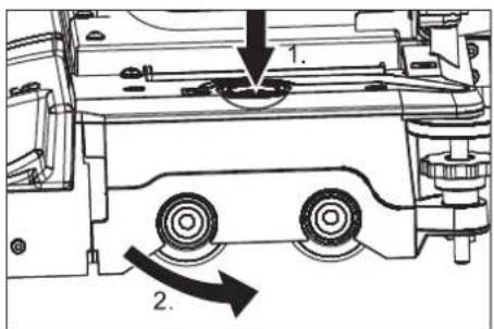
text_image
Technical diagram showing mechanical assembly with labeled components and directional arrows indicating motion or movement.text_image
Technical diagram of a mechanical assembly with labeled parts 1 and 21 Usisno crijevo
2 Spojka usisne konzole
→ Skinite usisno crijevo s usisne konzole.
→ Otpustite spojku usisne konzole.
→ Skinite usisnu konzolu.
natural_image
Technical line drawing of a mechanical clamp or bracket assembly (no text or symbols)1 Matice s nazubljenom glavom
text_image
Technical diagram of a curved mechanical component with labeled parts 1 and 2text_image
Technical diagram of a mechanical device with labeled parts 1 and 22006/42/EZ (+2009/127/EZ)
2014/30/EU

Chairman of the Board of Management
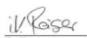
S. Reiser
Director Regulatory Affairs & Certification
71364 Winnenden (Germany)
Tel.: +49 7195 14-0
Fax: +49 7195 14-2212
Winnenden, 2019/05/01

Pre prve upotrebe Vašeg uređaja pročitajte ove originalno
www.kaercher.com/REACH
text_image
Technical diagram of a car interior with numbered components and exploded views, likely for maintenance or assembly reference.1 Priključak creva, automatika za punjenje
2 Rezervoar za svežu vodu
3 Indikator punjenja akumulatora (samo kod verzije Bp Pack)
4 Rezervoar prljave vode
5 Plovak
6 Ispusno crevo prljave vode
7 Utikač uređaja
8 Akumulatorski utikač
9 Akumulator
10 Strujni utikač punjača (samo kod verzije Bp Pack)
11 Usisna konzola
12 Ventil za svežu vodu
13 Mrežica za svežu vodu
14 Poklopac rezervoara sveže vode
15 Blok čistača
16 Nosač usisne konzole za jaka zaprljanja (rad u dva koraka)
17 Indikator napunjenosti rezervoara sveže vode
Crevo za ispuštanje sveže vode
18 Vozna pedala
19 Platforma za stajanje tokom rada
20 Sigurnosna papučica
21 Zatvarač
22 Komandni pult
23 Upravljač
24 Otkočna poluga, vožnja
25 Otkočna poluga, guranje
A Fioka za nakupljenu grubu prljavštinu (samo varijanta BR)
B Bočna zaštita od prskanja (samo varijanta BR)
Oznaka u boji
- Komandni elementi za proces čišćenja su žuti.
- Komandni elementi za održavanje i servis su svetlo sivi.
Indikator stanja akumulatora
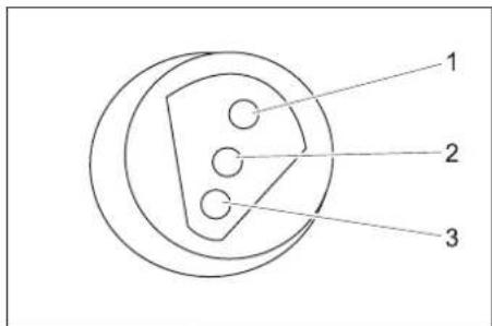
text_image
1 2 3| 1 zelena Svetli: | Postupak punjenja je završen. |
| 2 žuto Svetli: Završna faza punjenja. | |
| 3 crveno Svetli: | Postupak punjenja.Treperi: Inicijalizacija punjača. |
Komandni pult
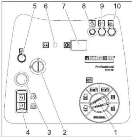
text_image
5 6 7 8 9 10 KARCHER® Professional B-42 PIB 4 3 2 11 Prekidač za izbor programa
2 Prekidač sa ključem
3 Prekidač za isključenje u nuždi (deblokira se okretanjem)
4 Prekidač za izbor smera vožnje, svetli izabrani smer vožnje
5 Sirena
6 Prikaz napunjenosti akumulatora
7 Brojač radnih sati
8 Osigurač upravljačke jedinice
9 Osigurač usisne turbine
10 Osigurač pogona četki
Prikaz napunjenosti akumulatora
| svetli Akumulator je napunjen. |
| treperi Akumulator mora da se napuni.Pogon četki i nanošenjerastvora deterdženta su deaktivirani. |
Prekidač za izbor programa

text_image
2 3 4 5 MAX MIN KARCHER 1 6natural_image
Technical line drawing of a vehicle battery pack with multiple circuit breakers and wiring (no text or symbols)→ Postavite akumulatore u uređaj.
→ Polove spojite priloženim spojnim kablovima.
PAŽNJA
Opasnost od oštećenja. Pazite na pravilno spajanje polova.
natural_image
Technical line drawing of a mechanical device with no visible text or symbolsnatural_image
Technical line drawing of a robotic device with internal components and directional arrows indicating motion (no text or symbols)Pričvrsna mesta
Skladištenje
△OPREZ
Opasnost od povreda i oštećenja! Pri skladištenju imajte u vidu težinu uređaja. Ovaj uređaj se sme skladištiti samo u zatvorenim prostorijama.
Nega i održavanje
△OPASNOST
Opasnost od povreda! Pre svih radova na uređaju prebacite prekidač sa ključem na "0" i izvucite ključ. Izvucite akumulatorski utikač.
⚠UPOZORENJE
Nakon isključivanja usisna turbina radi još neko vreme. Radove na održavanju obavljajte tek kad se usisna turbina potpuno zaustavi.
→ Ispustite i uklonite prljavu i preostalu svežu vodu.
Plan održavanja
Pre početka rada:
→ Proverite zaptivenost gornjeg dela uređaja na rezervoaru za prljavu vodu.
→ Proverite stanje guma na točkovima.
→ Proverite ispravnost položaja četke.
→ Proverite zaptivenost utičnih spojeva usisnog creva.
→ Proverite pričvršćenost usisne konzole (vidi "Radovi na održavanju").
→ Proverite zaptivenost zatvarača na crevu za ispuštanje prljave vode.
→ Proverite da li oba ispusna creva ispravno stoje u držačima.
→ Proverite ispravnost vozne pedale, kočnice i upravljača.
→ Kod elektrolitskih akumulatora proverite nivo kiseline i po potrebi dolijte destilisanu vodu.
Po završetku rada:
→ Ispraznite rezervoar prljave vode.
→ Rezervoar prljave vode isperite čistom vodom.
→ Očistite mrežicu i plovak u rezervoaru prljave vode (vidi "Radovi na održavanju").
→ Očistite rezervoar za svežu vodu.
→ Uključite usisavanje u trajanju od jednog minuta kako bi se sistem osušio.
→ Ispraznite i očistite fioku za nakupljenu grubu prljavštinu (samo varijanta BR).
→ Proverite istrošenost četke, po potrebi je očistite.
→ Proverite istrošenost gumica za usisavanje prljavštine na usisnoj konzoli, po potrebi ih očistite.
→ Uređaj prebrišite spolja vlažnom krpom natopljenom u rastvor blagog sredstva za pranje.
natural_image
Technical line drawing of a mechanical assembly with no visible text or symbols→ Podignite ručku spojnice usisne konzole.
→ Skinite usisnu konzolu.
Prevrtanje ili zamena gumica za usisavanje prljavštine
→ Skinite usisnu konzolu.
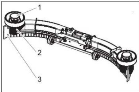
text_image
Technical diagram of a curved mechanical component with numbered parts labeled 1, 2, and 3.1 Zvezdasti pričvrsnik
2 Plastični deo
3 Gumica za usisavanje
→ Odvrnite zvezdaste pričvrsnike.
→ Skinite plastične delove.
→ Skinite gumice za usisavanje.
→ Gumice prevrnite naopako ili umetnite nove.
→ Nataknite plastične delove.
→ Zavijte i zategnite zvezdaste pričvrsnike.
Zamena valjkaste četke
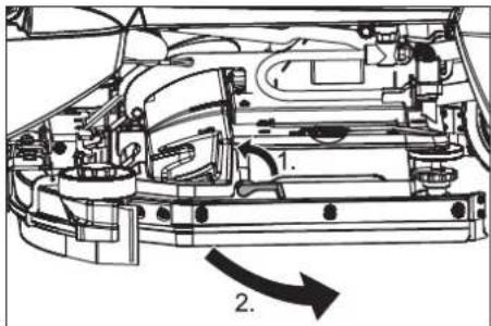
text_image
Technical diagram of a vehicle engine showing internal components and directional arrow indicating motion or flow.→ Otkočnu polugu preklopite na gore.
→ Zaštitu od prskanja preklopite prema napred.
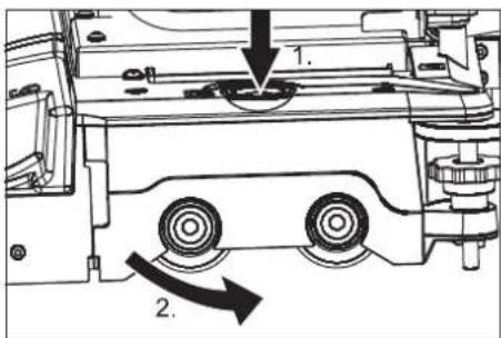
text_image
1. 2.→ Pritisnite taster za zamenu četke pa zatim poklopac na bloku četki okrenite u stranu.
→ Izvucite valjkastu četku.
→ Namestite i uglavite novu valjkastu četku.
→ Zatvorite poklopac, usmerite četke i uglavite u poklopac.
→ Zaštitu od prskanja preklopite nazad.
→ Spustite otkočnu polugu.
Radovi na održavanju BD 50/40 RS
Vađenje usisne konzole
text_image
Technical diagram of a mechanical assembly with labeled parts 1 and 21 Usisno crevo
2 Spojnica usisne konzole
→ Skinite usisno crevo sa usisne konzole.
→ Otpustite spojnicu usisne konzole.
→ Skinite usisnu konzolu.
Zamena ili prevrtanje gumica za usisavanje prljavštine
→ Izvadite usisnu konzolu.
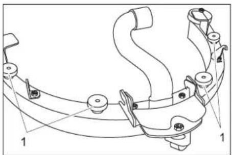
natural_image
Technical line drawing of a mechanical clamp or bracket assembly (no text or symbols)text_image
Technical diagram of a curved mechanical component with labeled parts 1 and 2text_image
Technical diagram of a fire extinguisher system with labeled components2006/42/EZ (+2009/127/EZ)
2014/30/EU

Chairman of the Board of Management
Director Regulatory Affairs & Certification
71364 Winnenden (Germany)
Tel.: +49 7195 14-0
Fax: +49 7195 14-2212
Winnenden, 2019/05/01

www.kaercher.com/REACH
text_image
Technical diagram of a car interior with numbered parts and exploded views, likely for maintenance or assembly reference.natural_image
Technical line drawing of a vehicle battery pack with multiple circuit breakers and wiring (no text or symbols)natural_image
Technical line drawing of a mechanical device with wheels and a handle (no text or symbols)natural_image
Technical line drawing of a robotic device with internal components and directional arrows indicating motion (no text or symbols)Точки за закрепване
Съхранение
⚠ПРЕДПАЗЛИВОСТ
natural_image
Technical line drawing of a mechanical assembly with no visible text or symbolstext_image
Technical diagram of a curved mechanical component with numbered parts labeled 1, 2, and 3.text_image
Technical diagram of a car engine showing internal components and directional arrow indicating motion or flowtext_image
Technical diagram showing mechanical assembly with labeled components and directional arrows indicating motion or movement.text_image
Technical diagram of a mechanical assembly with labeled parts 1 and 2natural_image
Technical line drawing of a mechanical clamp or bracket assembly (no text or symbols)1 Гайка с назъбка
text_image
Technical diagram of a curved mechanical component with labeled parts 1 and 2text_image
Technical diagram showing a mechanical assembly with labeled parts 1 and 2, likely illustrating a component or assembly.
Chairman of the Board of Management
Director Regulatory Affairs & Certification
71364 Winnenden (Germany)
Tel.: +49 7195 14-0
Fax: +49 7195 14-2212
Winnenden, 2019/05/01

www.kaercher.com/REACH
text_image
Technical diagram of a car interior with numbered parts and exploded views, likely for maintenance or assembly reference.natural_image
Technical line drawing of a vehicle chassis with wiring and mounting brackets (no text or symbols)Akude mahamonteerimine
natural_image
Technical line drawing of a mechanical lift or lift assembly (no text or symbols)natural_image
Technical line drawing of a robotic device with internal components and directional arrows indicating motion (no text or symbols)Kinnituspunktid
Hoiulepanek
ETTEVAATUS
Imiotsaku mahamonteerimine
→ Tömmake imivoolik imotsakult maha.
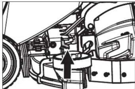
natural_image
Technical line drawing of a vehicle's internal components, showing engine, motors, and structural parts (no text or labels)text_image
Technical diagram of a curved mechanical component with numbered parts labeled 1, 2, and 3.1 Tähtnupp
2 Plastdetail
3 Imihuul
text_image
Technical diagram of a car engine showing internal components and directional arrows labeled 1 and 2.text_image
Technical diagram showing mechanical assembly with labeled components and directional arrows indicating motion or movement.Imiotsaku mahamonteerimine
text_image
Technical diagram of a mechanical assembly with labeled parts 1 and 21 Imivoolik
2 Imiotsaku muhv
natural_image
Technical line drawing of a mechanical clamp or bracket assembly (no text or symbols)1 Mutter
text_image
Technical diagram of a curved mechanical component with labeled parts 1 and 21 Imihuul
2 Imiotsaku sisend
→ Võtke imihuuled imiotsaku sisendilt maha.
Märkus:
text_image
Technical diagram showing a mechanical assembly with labeled parts 1 and 2, likely illustrating a valve or pump mechanism.71364 Winnenden (Germany)
Tel.: +49 7195 14-0
Fax: +49 7195 14-2212
Winnenden, 2019/05/01

www.kaercher.com/REACH
text_image
Technical diagram of a car interior with numbered parts and exploded views, likely for maintenance or assembly reference.natural_image
Technical line drawing of a vehicle chassis with battery pack and wiring (no text or symbols)natural_image
Technical line drawing of a mechanical device with wheels and mounting brackets (no text or symbols)natural_image
Technical line drawing of a robotic device with internal components and directional arrows (no text or symbols)natural_image
Technical line drawing of a mechanical assembly with no visible text or symbolstext_image
Technical diagram of a mechanical component with numbered parts labeled 1, 2, and 3.text_image
Technical diagram of a car engine showing internal components and directional arrows labeled 1 and 2.text_image
Technical diagram showing mechanical components with numbered annotations and directional arrows indicating motion or assembly.text_image
Technical diagram of a vehicle's internal components with numbered parts labeled 1 and 21 Sūkšanas šlūtene
natural_image
Technical line drawing of a mechanical clamp or bracket assembly (no text or symbols)1 Rievotais uzgrieznis
text_image
Technical diagram of a curved mechanical component with labeled parts 1 and 2text_image
Technical diagram showing a mechanical assembly with labeled parts 1 and 2, likely illustrating a valve or component assembly.
Chairman of the Board of Management
S. Reiser
Director Regulatory Affairs & Certification
71364 Winnenden (Germany)
Tel.: +49 7195 14-0
Fax: +49 7195 14-2212
Winnenden, 2019/05/01
www.kaercher.com/REACH
text_image
Technical diagram of a car interior with numbered components and exploded views, likely for maintenance or assembly reference.1 Žarnos jungtis, pildymo automatika
2 Švaraus vandens bakas
3 Jkroviklio büsenos indikatorius (tik „Bp Pack“ modelyje)
4 Užteršto vandens bakas
5 Plūduras
natural_image
Technical line drawing of a vehicle chassis with multiple battery cells and wiring (no text or symbols)natural_image
Technical line drawing of a mechanical device with no visible text or symbolsnatural_image
Technical line drawing of a robotic device with internal components and a magnified inset showing internal structure (no text or symbols)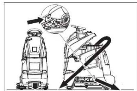
natural_image
Technical line drawing of a robotic device with internal components and directional arrows indicating motion (no text or symbols)Tvirtinimo taškai
Laikymas
ATSARGIAI
natural_image
Technical line drawing of a mechanical assembly with no visible text or symbols→ Pakelkite siurbimo rémelio sankabos rankeną.
→ Nuimkite siurbimo rémelj.
text_image
Technical diagram of a mechanical component with numbered parts labeled 1, 2, and 3text_image
Technical diagram of a car engine showing internal components and directional arrows labeled 1 and 2.text_image
Technical diagram showing mechanical assembly with labeled components and directional arrows indicating motion or force directions.text_image
Technical diagram of a mechanical assembly with labeled parts 1 and 21 Siurbimo žarna
2 Siurbimo rémelio mova
natural_image
Technical line drawing of a mechanical clamp or bracket assembly (no text or symbols)1 Rievétoji veržlé
text_image
Technical diagram of a curved mechanical component with labeled parts 1 and 2text_image
Technical diagram of a spray gun system with labeled components 1 and 2
Chairman of the Board of Management

Director Regulatory Affairs & Certification
71364 Winnenden (Germany)
Tel.: +49 7195 14-0
Fax: +49 7195 14-2212
Winnenden, 2019/05/01
www.kaercher.com/REACH
text_image
Technical diagram of a car interior with numbered parts and exploded views, likely for maintenance or assembly reference.natural_image
Technical line drawing of a vehicle chassis with battery, wiring, and mounting bracket (no text or symbols)natural_image
Technical line drawing of a mechanical device with wheels and a handle (no text or symbols)natural_image
Technical line drawing of a cleaning or repair machine with no visible text or symbolsТочки кріплення
Зберігання
⚠ОБЕРЕЖНО
natural_image
Technical line drawing of a vehicle's internal components, showing engine, suspension, and wheel assembly (no text or labels)text_image
Technical diagram of a curved mechanical component with numbered parts labeled 1, 2, and 3.text_image
Technical diagram of a car engine showing internal components and directional arrows labeled 1 and 2.text_image
Technical diagram showing mechanical components with numbered annotations indicating parts of a device or assembly.text_image
Technical diagram of a mechanical assembly with labeled parts 1 and 2natural_image
Technical line drawing of a mechanical clamp or bracket assembly (no text or symbols)1 Гайка з насічкою
text_image
Technical diagram of a curved mechanical component with numbered parts labeled 1 and 2text_image
Technical diagram of a mechanical device with labeled components 1 and 2
Chairman of the Board of Management

Director Regulatory Affairs & Certification
71364 Winnenden (Germany)
Tel.: +49 7195 14-0
Fax: +49 7195 14-2212
Winnenden, 2019/05/01