B 90 R - Sweeper Kärcher - Free user manual and instructions
Find the device manual for free B 90 R Kärcher in PDF.
| Product type | Sweeper (floor cleaner) |
| Brand | Kärcher |
| Model | B 90 R |
| Working width | 550 / 650 / 750 mm (according to version R/D) |
| Brush diameter | 105 / 315 mm (R55/R65/R75) or 105/365/410 mm (D55/D65/D75) |
| Max. travel speed | 6 km/h |
| Max. permissible slope | 10 % |
| Theoretical cleaning area | 3300 / 3900 / 4500 m²/h (depending on width) |
| Fresh/waste water tank volume | 90 l / 90 l |
| Waste container volume (R head) | 5 / 6 / 7 l (depending on width) |
| Permissible total weight | 460 kg |
| Transport weight (with 180 Ah battery) | 309 kg |
| Nominal voltage | 24 V |
| Battery capacity | 180 Ah (240 Ah optional) |
| Average power consumption | 2200 W |
| Traction motor power | 600 W |
| Suction motor power | 750 W (R55/R65/R75) or 550 W (D55/D65/D75) |
| Brush motor power | 2 x 600 W |
| Sound pressure level (LpA) | 69 dB(A) |
| Total vibration value | < 2.5 m/s² |
| Dimensions (L x W x H) | 1450 x 720-810 x 1180 mm |
| Main functions | Wet cleaning, suction, polishing, scrubbing, detergent dosing |
| Safety devices | Emergency stop button, seat cut-out switch, parking brake |
| Routine maintenance | Drain dirty water, clean filters, charge battery, replace brushes/squeegees |
| Spare parts | Only Kärcher original accessories and parts |
| Warranty | According to country conditions, through dealer or authorized service |
Frequently Asked Questions - B 90 R Kärcher
User questions about B 90 R Kärcher
0 question about this device. Answer the ones you know or ask your own.
Ask a new question about this device
Download the instructions for your Sweeper in PDF format for free! Find your manual B 90 R - Kärcher and take your electronic device back in hand. On this page are published all the documents necessary for the use of your device. B 90 R by Kärcher.
USER MANUAL B 90 R Kärcher
natural_image
Line drawing of a cleaning or cleaning vehicle interior (no text or symbols)Deutsch 5
English 13
Français 21
Italiano 30
Nederlands 39
Español 47
Português 56
Dansk 65
Norsk 73
Svenska 81
Suomi 89
Ελληνικά 97
Türkçe 108
Русский 116
Magyar 126
Čeština 134
Slovenščina 142
Polski 150
Românește 158
Slovenčina 166
Hrvatski 174
Srpski 182
Български 190
Eesti 199
Latviešu 207
Lietuviškai 215
Українська 223
العربية 239
Register and win! www.kaercher.com/register-and-win


59623830 05/19
text_image
Technical diagram of a car cleaning or maintenance system with numbered components and close-ups of internal components.
text_image
10 11 12 13 14 15 9 8 i 1 2 7 6 3 5 4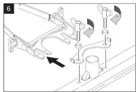
natural_image
Mechanical assembly diagram showing clamping mechanism with no visible text or symbols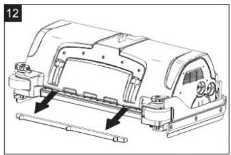
natural_image
Technical line drawing of a vehicle chassis with mounting brackets and structural components (no text or symbols)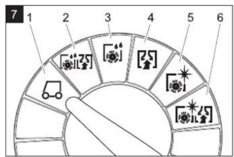
text_image
7 1 2 3 4 5 6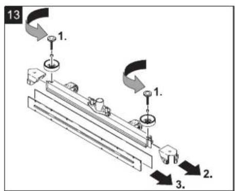
text_image
13 1. 1. 2. 3.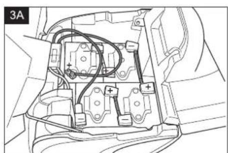
natural_image
Technical line drawing of an internal electrical or mechanical component with no visible text or symbols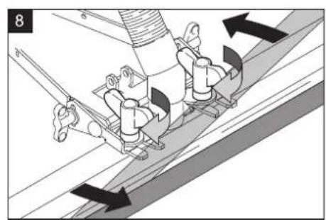
natural_image
Mechanical assembly diagram showing clamping mechanism with arrows indicating motion (no text or symbols)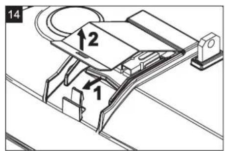
text_image
14 2 1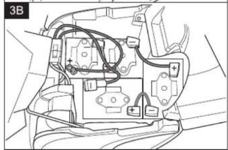
natural_image
Technical line drawing of an automotive electrical panel with wiring and components (no text or symbols)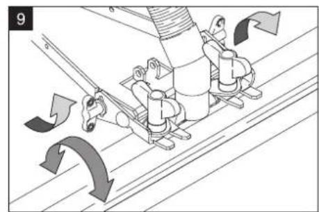
text_image
9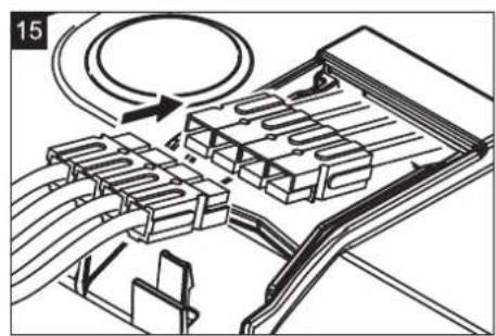
natural_image
Technical diagram of a mechanical assembly with rollers and housing (no text or symbols)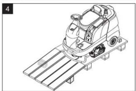
natural_image
Line drawing of a cleaning or cleaning machine on a platform (no text or symbols)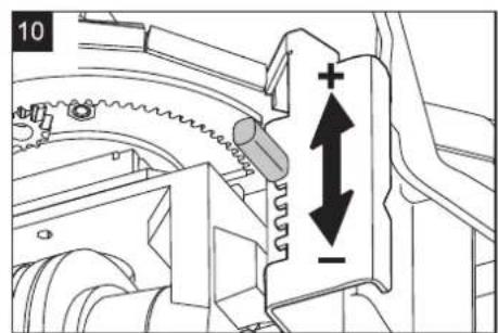
text_image
10 +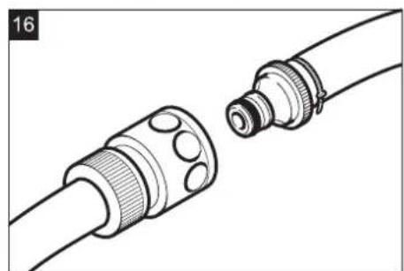
natural_image
Technical illustration of two connected cable connectors with no text or symbols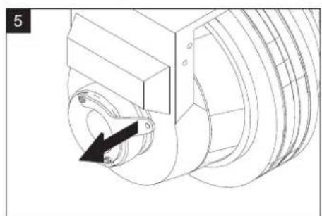
natural_image
Technical line drawing of a mechanical assembly with a circular component and a black arrow indicating direction (no text or symbols)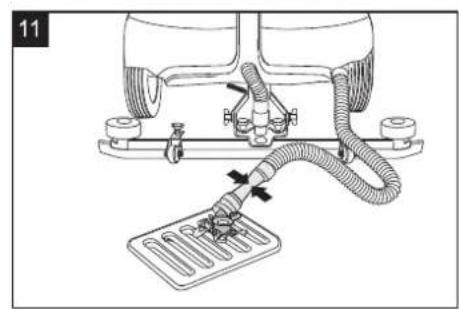
text_image
11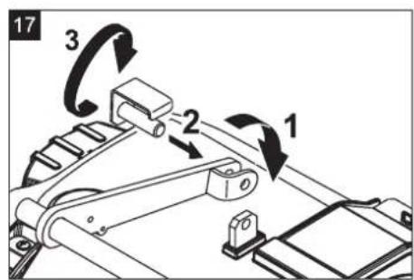
text_image
17 3 2 1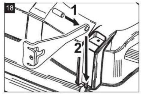
text_image
18 1 2'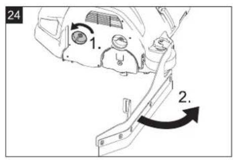
text_image
24 1. 2.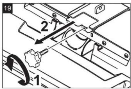
text_image
19 2 1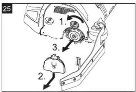
text_image
25 1. 3. 2.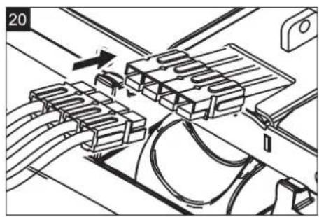
natural_image
Technical diagram of a mechanical assembly with rollers and connectors (no text or symbols)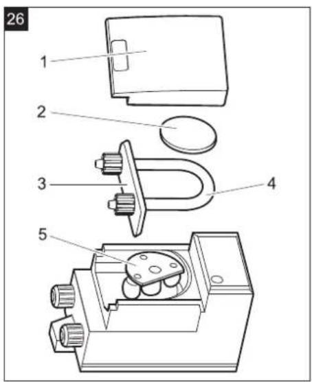
text_image
26 1 2 3 4 5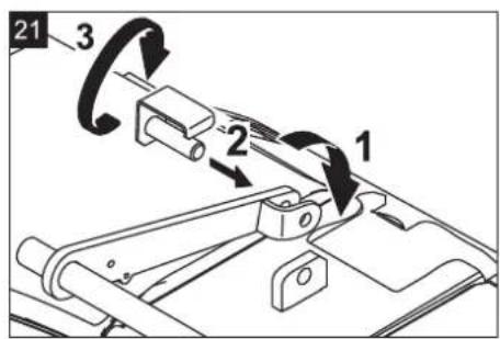
text_image
21 3 2 1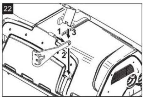
text_image
22 1 3 2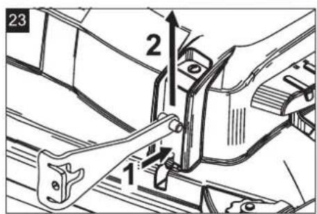
text_image
23 1Infobutton (Variante Adv)

Chairman of the Board of Management

S. Reiser
Director Regulatory Affairs & Certification
71364 Winnenden (Germany)
Tel.: +49 7195 14-0
Fax: +49 7195 14-2212
Winnenden, 2019/05/01
Please read and comply with these original instructions prior
to the initial operation of your appliance and store them for later use or subsequent owners.
Contents
Safety instructions ..... EN 1
Function.....EN 1
Proper use.....EN 1
Environmental protection.....EN 1
Control elements ..... EN 1
Before Startup ..... EN 2
Operation.....EN 3
Transport....EN 5
Storage....EN 5
Care and maintenance ..... EN 5
Troubleshooting.....EN 6
Technical specifications.....EN 8
Accessories and Spare Parts . EN 8
Warranty....EN 8
EU Declaration of Conformity. EN 8
Safety instructions
Before using the appliance for the first time, read and observe these operating instructions and the accompanying brochure: Safety information for brush cleaning units 5.956-251.0.
The machine has been approved for use on surfaces with gradients of up to 10%.
Safety Devices
Safety devices serve to protect the user and must not be rendered in operational or their functions bypassed.
Emergency-stop button
To put all functions out of operation immediately: Press emergency-stop button.
– The machine comes to a sudden halt when you press the emergency-stop button.
- The emergency-stop has a direct effect on all machine functions.
– The display continues.
Safety Switch
Switches off the drive motor after a short delay, if the operator leaves the operator seat during operation or while moving.
Hazard levels
△DANGER
Pointer to immediate danger, which leads to severe injuries or death.
△WARNING
Pointer to a possibly dangerous situation, which can lead to severe injuries or death.
△CAUTION
Pointer to a possibly dangerous situation, which can lead to minor injuries.
ATTENTION
Pointer to a possibly dangerous situation, which can lead to property damage.
Function
The scrubber vacuum is used for wet cleaning or polishing of level floors.
You can adjust the machine to suit the cleaning task by modifying the settings for water quantity, contact pressure of the brushes, detergent quantity and driving speed.
Proper use
This appliance is suited for the commercial use, e.g. in hotels, schools, hospitals, factories, shops, offices, and rental companies.
Use this appliance only as directed in these operating instructions.
- The appliance may only be used for the cleaning of hard surfaces that are not sensitive to moisture and polishing operations.
– This appliance is intended for inside use.
- The application temperature ranges from +5^ to +40^ .
- The appliance is not suited for the cleaning of frozen grounds (e.g. in cold stores).
- The appliance is suitable for a max. water depth of 1cm . Do not drive into an area where there is a risk of this max. water height being exceeded.
- The appliance may only be equipped with original accessories and spare parts.
– The appliance is not intended for the cleaning of public traffic routes.
- The machine should not be used on surfaces that are sensitive to pressure. Please consider the allowed load per surface unit of the floor. Details of load per surface unit can be found in the technical data.
– The appliance is not suited for the use in potentially explosive environments.
- The machine should not be used to suck in inflammable gases, undiluted acids or solvents.
This includes petrol, thinning agents or hot oil that can form an explosive mixture when it comes in contact with sucked air. Do not use acetone, undiluted acids and solvents as they are aggressive towards the materials from which the appliance is made.
Environmental protection

The packaging materials are recyclable. Please do not throw packaging in the domestic waste but pass it on for recycling.
Old units contain valuable recyclable materials. Batteries, oil and similar substances may not be released into the environment. Therefore please dispose of old units through suitable collection systems.
Notes about the ingredients (REACH)
You will find current information about the ingredients at:
www.kaercher.com/REACH
Control elements
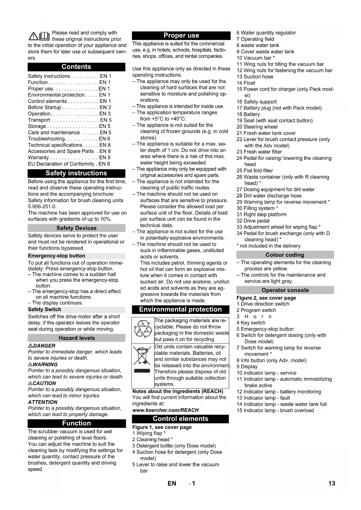
Figure 1, see cover page
1 Wiping flap *
2 Cleaning head *
3 Detergent bottle (only Dose model)
4 Suction hose for detergent (only Dose model)
5 Lever to raise and lower the vacuum bar
6 Water quantity regulator
7 Operating field
8 waste water tank
9 Cover waste water tank
10 Vacuum bar *
11 Wing nuts for tilting the vacuum bar
12 Wing nuts for fastening the vacuum bar
13 Suction hose
14 Float
15 Power cord for charger (only Pack model)
16 Safety support
17 Battery plug (not with Pack model)
18 Battery
19 Seat (with seat contact button)
20 Steering wheel
21 Fresh water tank cover
22 Lever for brush contact pressure (only with the Adv model)
23 Fresh water filter
24 Pedal for raising/ lowering the cleaning head
25 Flat fold filter
26 Waste container (only with R cleaning head) *
27 Dosing equipment for dirt water
28 Dirt water discharge hose
29 Warning lamp for reverse movement *
30 Filling system *
31 Right step platform
32 Drive pedal
33 Adjustment wheel for wiping flap *
34 Pedal for brush exchange (only with D cleaning head) *
* not included in the delivery
Colour coding
- The operating elements for the cleaning process are yellow.
– The controls for the maintenance and service are light gray.
Operator console
Figure 2, see cover page
1 Drive direction switch
2 Program switch
3 H o r n
4 Key switch
5 Emergency-stop button
6 Switch for detergent dosing (only with Dose model)
7 Switch for warning lamp for reverse movement *
8 Info button (only Adv. model)
9 Display
10 Indicator lamp - service
11 Indicator lamp - automatic immobilizing brake active
12 Indicator lamp - battery monitoring
13 Indicator lamp - fault
14 Indicator lamp - waste water tank full
15 Indicator lamp - brush overload
Before Startup
Batteries

Observe the directions on the battery, in the instructions for use and in the vehicle operating instructions

Wear eye protection

Keep children away from acid and batteries

Danger of explosion

Fire, sparks, naked flames and smoking must be strictly avoided

Danger of chemical burns

First aid

Warning note

Disposal

Do not throw the battery into the regular waste
DANGER
Risk of explosion!
Do not place tools or similar items on the battery. Risk of short-circuit and explosion. Risk of injury. Ensure that wounds never come into contact with lead. Always clean your hands after having worked with batteries.
Insert batteries and connect
The "Pack" model contains built-in batteries.
→ Swivel the seat to the front.
Figure 3, see cover page
→ Insert batteries.
Note:
The two recommended battery types are housed differently in different arrangements in the device.
| Layout A (Fig. 3A) 180 Ah | |
| Layout B (Fig. 3B) 240 Ah |
ATTENTION
Risk of damage. Ensure correct polarity.
→ Lubricate the battery pole with pole grease.
→ Connect pole using the enclosed connecting cable.
→ Connect the connection cable to the free battery poles (+) and (-).
→ Insert battery plug.
→ Raise the safety support und and swivel seat to the bottom.
ATTENTION
Risk of damage due to full discharge! Charge the batteries before commissioning the appliance.
Charge the batteries
Note:
The device is equipped with a safety mechanism to prevent total discharge, i.e. when the permissible minimum capacity is reached, then the machine can only be driven and existing lamps can be switched on. In such a case, the battery monitoring symbol on the control console glows red.
→ Drive the appliance directly to the charging station; avoid any steep gradients in the process.
Note:
When using other batteries (e.g. batteries from other manufacturers), the total discharge protection level for the respective battery must be reset by the Kärcher after-sales service.
△DANGER
Risk of electric shock. Observe power supply net and fuse protection – see "Charger". Use the charger in dry rooms with sufficient ventilation only!
Note:
Average charging time is approx. 10 -12 hours.
The recommended chargers (suitable for the batteries used) are regulated electronically and will automatically terminate the charging process.
△DANGER
Danger of explosion. Wet batteries may only be charged with the seat tilted up.
"Pack" model
→ Tilt the seat upward.
→ Take the power cord out of its holder and insert the plug into the socket. The display will show the charging status of the batteries.
Note:
All cleaning and driving functions are blocked during the charging process. The functions are disabled until a charging period of at least 90 minutes has elapsed and the mains plug has been unplugged again.
→ After the charging process, pull the power plug and insert into the holder on the appliance.
Model without integrated charger
→ Tilt the seat upward.
→ Remove battery plug and join it to the charging cable.
→ Connect the charger to the mains and turn it on.
→ Switch off the charger and remove the plug from the socket after you have finished charging.
→ Pull the battery cable from the charger cable and connect it to the machine.
Low maintenance batteries (wet batteries)
→ Add distilled water one hour before the charging process comes to an end; follow the correct acid level. There are corresponding indicators on the battery. At the end of the charging process, all cells must gas.
⚠ WARNING
Danger of causticization!
- Adding water to the battery in its discharged state can cause the acid to leak.
- Use safety glasses while handling battery acid and follow the safety instructions to avoid personal injury or damage to clothes.
- Should the acid spray on to the skin or clothes, rinse immediately with lots of water.
ATTENTION
Risk of damage!
- Use only distilled or desalinated water (EN 50272-T3) for filling the battery.
- Do not add any substances (so-called performance improving agents), else warranty claims will not be entertained.
Recommended batteries, chargers
| Order No. | |
| Battery pack, 180 Ah, maintenance-free (4 batteries) | 6.654-124.0 |
| Battery pack, 240 Ah, maintenance-free (4 batteries) | 6.654-119.0 |
| Charger for maintenance-free batteries | 6.654-125.0 |
Maximum battery dimensions
| Layout A B | ||
| Length 244 mm 312 mm | ||
| Width 190 mm 182 mm | ||
| Height 275 mm 365mm |
Removing the batteries
→ Turn main key to "0" and remove it.
→ Swivel the seat to the front.
→ Pull out the battery plug.
→ Clamp off the minus pole of the battery.
→ Clamp off the remaining cables from the battery.
→ Remove the batteries.
→ Dispose of the used batteries according to the local provisions.
Unloading
Note:
Press the emergency-stop button to immediately deactivate all functions and turn the key switch to the "0" position.
→ Four floor boards of the pallet are fastened with screws. Unscrew these boards.
Figure 4, see cover page
→ Place the boards on the edge of the pallet. Place the boards in such a way that they lie in front of the four wheels of the machine. Fasten the boards with screws.
→ Slide the four support beams included in the packaging under the ramp.
→ Remove the wooden bars in front of the wheels.
Figure 5, see cover page
→ Pull the brake lever and push the appliance down the ramp with the level pulled.
or
→ Release emergency-stop button by turning.
→ Set main switch to "1".
→ Press the drive direction switch and slowly move the machine down from the ramp.
→ Set main switch back to "0".
Install cleaning head
The procedure for changing the cleaning head is described in the chapter "Maintenance Tasks".
Note:
On some models, the cleaning head is already installed.
Installing the Brushes
The installation of the brushes is described in the chapter "Maintenance Tasks".
Installing the Vacuum Bar
Figure 6, see cover page
→ Insert the vacuum bar into the vacuum bar suspension in such a manner that the profiled sheet is positioned above the suspension.
→ Tighten the wing nuts.
→ Insert the suction hose.
Operation
DANGER
Risk of injury. Do not use the device without an overhead guard to protect against falling objects in areas in which there is a possibility of operators being stuck by falling objects.
Note:
Press emergency-stop switch to immediately switch off all functions of the machine.
Check parking brake
△DANGER
Risk of accident. Prior to every operation, the parking brake must be checked for proper function on a level ground.
→ Take the seating position.
→ Release emergency-stop button by turning.
→ Set the key switch to "1".
→ Select travel direction.
→ Gently depress drive pedal.
The brake must get released and you must be able to hear it (the control lamp for immobilizing brake on the console switches off). The machine must roll slightly on a plane surface. When the pedal is released, the brake falls in an audible manner. Switch off the machine and call the aftersales service if the above-mentioned events do not occur.
Driving
△DANGER
Risk of accident. If the device does no longer show any braking effect, proceed as follows:
If the device does not come to a halt on a ramp with a gradient of 2% when you release the drive pedal, then the emergency-stop button may be pressed for safety reasons only if the mechanical functioning of the immobilizing brake has been checked properly before commissioning the device.
→ Switch off the machine only after it comes to a complete halt (on an even surface) and call up the aftersales service!
→ Further, follow all warning instructions for braking.
△DANGER
Danger of tipping if gradient is too high.
→ The gradient in the direction of travel should not exceed 10%.
Danger of tipping when driving round bends at high speed.
Danger of slipping on wet floors.
→ Drive slowly when cornering. Danger of tipping on unstable ground.
→ Only use the machine on sound surfaces.
Danger of tipping with excessive sideways tilt.
→ The gradient perpendicular to the direction of travel should not exceed 10%.
Driving
→ Release emergency-stop button by turning.
→ Sit on the seat and set main switch to "1".
→ Set the drive direction using the drive direction button at the operator console.
→ Determine the driving speed by pressing the drive pedal.
→ Stop the machine: Release the drive pedal.
Note:
The direction of travel can also be changed while driving. This way even very dull spots can be polished by driving back and forth several times.
Display
When switching on the display, the following messages will appear in sequence:
- „
“: The control conducts a self-test. - „Water E----F“ (model Adv): Water level in the fresh water tank (lasts for 6 seconds).
„OpHrs xxxxxhxxm+“ (Classic model): Operating hours (lasts for 6 seconds) - "Battery: E----F": Charging status of battery.
Overload
In case of overloading, the drive motor automatically switches off after a certain period. A fault message is displayed on the console. The concerned unit gets switched off if the controls get overheated.
→ Allow machine to cool down at least for 15 minutes.
→ Turn the main switch to "0" and turn it back to "1".
Filling in detergents
Detergent
ATTENTION
Risk of damage. Only use the recommended detergents. With other detergents, the operator bears the increased risk regarding the operational safety and danger of accident.
Only use detergents that are free from solvents, hydrochloric acid and hydrofluoric acid.
△CAUTION
Follow the safety instructions for using detergents.
Note:
Do not use highly foaming detergents. Recommended detergents:
| Application Detergent | |
| Routine cleaning of all water resistant floors | RM 746RM 780 |
| Routine cleaning of glossy surfaces (e.g. granite) | RM 755 es |
| Routine cleaning and basic cleaning of industrial floors | RM 69 ASF |
| Routine cleaning and basic cleaning of fine stoneware tiles | RM 753 |
| Routine cleaning of tiles in sanitary areas | RM 751 |
| Cleaning and disinfection in sanitary areas | RM 732 |
| Removal of coating from all alkali-resistant floors (e.g. PVC) | RM 752 |
| Removal of coating from li-noleum floors | RM 754 |
Fresh water
→ Open the cover of the fresh water reservoir.
→ Fill fresh water (max. 60 °C) until 15 mm below the upper edge of the tank.
→ Pour in detergent.
Note:
If detergent is added to the detergent tank first before the water, this can result in a formation of a lot of foam.
→ Close the cover of the fresh water reservoir.
Note:
Fill up the fresh water tank completely prior to the initial start-up to bleed the water pipe system.
Filling system (optional)
→ Connect the water hose to the connection neck on the filling system.
→ Open the water supply.
Once the maximum fill level is reached, the built-in floater valve will stop the water inflow.
→ Shut off water supply.
→ Remove the water hose.
Metering system (only Dose model)
Detergent is added to the fresh water on the way to the cleaning head with the help of a dosaging device.
→ Place the detergent bottle into the device.
→ Close the bottle lid.
→ Insert the suction hose of the dosaging equipment into the bottle.
Note:
The dosing unit can be used to add 3% detergent at maximum. With higher dosage the detergent must be put into the fresh water tank.
ATTENTION
Risk of clogging due to dried detergent when the detergent is added to the fresh water tank of the Dose version. The flow meter of the dosing equipment can agglutinate on account of drying detergent and hamper the functioning of the dosing equipment. Subsequently rinse the fresh water tank and the appliance with clear water. For rinsing, select cleaning programme with application of water at the programme selector switch. Set the water quantity to the highest value, set the detergent dosage to 0%
Note:
The appliance is equipped with a fresh water indicator in the display. If the fresh water tank is empty, the function of adding detergent gets deactivated. The cleaning head continues to work without liquid supply.
Cleaning Programs
Figure 7, see cover page
1 Driving
Driving to the Place of Use.
2 Scrubbing suction
Wet clean the floor and vacuum up dirt water.
3 Wet scrubbing
Wet clean the floor and allow the detergent to react.
4 Vacuuming
Suck in the dirt fleet.
5 Polishing
Polishing the floor without the application of liquid.
6 Scrub the floor without applying water (vacuum polishing)
Polish the floor without applying any fluid and suck in the polishing dust.
Note:
Depending on the program, the suction bar and the cleaning head must also be lowered with the appropriate control elements to perform the selected program.
Info button (only Adv. model)
Use the Info button to select the menu items and do the settings.
- Turning the button to the right/left scrolls through the menus forward/backward.
- The selected setting gets accepted by pressing the button.
Settings (only Adv. model)
You can make the settings for the different cleaning programs in the operator menu. Different parameters can be set based on the cleaning program. The settings are done using the Info button.
Operator menu
→ Release emergency-stop button by turning.
→ Sit on the seat and set main switch to "1".
The display shows the battery charging status and the fresh water level.
→ Select cleaning program.
→ Call the operator menu by turning the info button.
→ Select the desired parameter by turning the Info button.
→ Press Info button - the set value blinks.
→ Reset the parameter by turning the info button.
→ Accept modified setting by pressing the Info button or wait till the set value is accepted automatically.
Note:
If the selected parameter does not change within 10 seconds, then the display goes back to displaying the battery charging status and the fresh water level.
The same cleaning parameter can have individual settings for each cleaning program.
All settings are saved, even if the device is de-energized.
Adjustable parameters
| Adjustable parameters | min:step :max | Remark |
| Cleanspeed (max. cleaning speed) | 1:1:6 1=1 | km/h, 6=6km/h |
| FACT (brush speed) | - | P o Whisper Fine |
| Vacuum (suction performance) | - | Low High |
| Only with Dose model | ||
| Chemical/Agent (detergent metering) | 0.5%:0.5 %:3% | - |
Info menu
→ Turn the info button until "Information-menu" is displayed.
→ Retrieve the info menu by pressing the info button.
The following information can be displayed by turning the info button:
Display Significance
| Ophrs xxxxxhxxm+ | Operating hour counterWhen the counter is running, "+" will be displayed |
| Water E----F Water level in fresh water tank"C" blinks while the metering pump is operating (only Dose model) | |
| Speed: xkm/h Current speed | |
| Alfred/Kärcher Manufacturer | |
| B90R Dxx Appliance description | |
| Prog.Vers. x.x Software version | |
| Exit Inform.menu | Exit the info menu by pressing the info button. |
Setting the water quantity
→ Set the water quantity at the regulation knob according to the dirt level and the type of flooring.
Raise/lower the cleaning head
Lower
→ Press down the rear surface of the pedal to raise/lower the cleaning head, release and let the pedal move upwards. The brush drive will start as soon as the cleaning head is lowered.
Raise
→ Press down the front surface of the pedal to raise/lower the cleaning head and lock it.
Raise/lower the vacuum bar
Lower
→ Pull the lever up to raise/lower the vacuum bar, press toward the outside and lower.
The suction process will start as soon as the level is moved down.
Raise
→ Pull the lever to raise and lower the vacuum bar up and lock.
w Setting the Vacuum Bar
Oblique position
To improve the vacuuming result on tiled floors the vacuum bar can be turned to an oblique position of up to 5^ .
Figure 8, see cover page
→ Release the wing nuts.
→ Turn the vacuum bar.
→ Tighten the wing nuts.
Inclination
If the vacuum result is unsatisfactory the inclination of the straight vacuum bar can be modified.
Figure 8, see cover page
→ Release the wing nuts.
→ Tilt the vacuum bar.
→ Tighten the wing nuts.
Adjust brush contact pressure (only with the Adv model)
Figure 10, see cover page
→ Unlock the lever for the brush contact pressure to the left and relock to the right.
– Level down: Reduce contact pressure.
– Level up: Increase contact pressure.
Adjust wiper flaps (only with the Adv model)
→ Adjust the wiper flaps by turning the adjustment wheel so that they touch the floor.
→ Turn the adjustment wheel an additional turn toward the bottom.
Emptying the waste Water tank
Note:
Overflow waste water tank. If the dirt water tank is full, the suction turbine switches off and the indicator lamp "waste water tank full" begins to blink. All cleaning programs with suction are blocked for one minute. Empty the waste water tank.
△CAUTION
Please observe the local provisions regarding the wastewater treatment.
→ Take the dirt water discharge hose from the support and lower above a suited collection device.
Figure 11, see cover page
→ Let off water by opening the dosage device at the discharge hose.
→ The rinse the dirt water reservoir with clear water.
Emptying the Fresh Water Tank
→ Unscrew the filter cup of the fresh water filter and let the fresh water tank drain completely.
→ Replace the filter cup.
Empty waste container (only with R cleaning head)
→ Check the waste container. If needed, remove and empty waste container after work.
Shutting down
→ Turn main key to "0" and remove it.
→ Secure the machine with wheel chocks to prevent it from rolling away.
Transport
DANGER
Risk of injury! When loading or unloading the machine, it may only be operated on gradients of max. 10%. Drive slowly.
⚠CAUTION
Risk of injury and damage! Observe the weight of the appliance when you transport it.
→ When transporting in vehicles, secure the appliance according to the guidelines from slipping and tipping over.
With mounted D cleaning head
→ Remove brushes from the brush head.
Storage
△CAUTION
Risk of injury and damage! Note the weight of the appliance in case of storage.
→ This appliance must only be stored in interior rooms.
→ Select the storage site for the appliance taking into consideration the permissible total weight of the appliance in order not to impact its stability.
Care and maintenance
⚠Danger
Risk of injury. Before carrying out any tasks on the machine, set the main key to "0" and remove it. Press emergency-stop button.
Place the appliance on a stable, even surface and disconnect the battery.
⚠ WARNING
Suction turbine will continue to run for a while after switch-off. Carry out maintenance tasks only after the suction turbine has come to a halt.
→ Drain and dispose of the dirt water and the residual fresh water.
Maintenance schedule
After the work
ATTENTION
Risk of damage. Do not sluice the appliance with water and do not use aggressive detergents.
→ Drain off dirt water.
→ Check the flat folded filter, clean if required
→ Only with R cleaning head Remove bulk waste container and empty it.
→ Clean the outside of the appliance with a damp cloth which has been soaked in mild detergent.
→ Clean the vacuum lips and the wiping lips, check for wear and replace if required.
→ Check the brushes for wear, replace if required.
→ Charge the battery:
If the charging state of the battery is under 50%, charge the battery fully and without interruption.
If the charging state of the battery is over 50%, only recharge the battery if the entire operation duration will be required when next used.
Weekly
→ When used regularly, charge the battery fully and without interruption at least once a week.
Monthly
→ Check battery pole for oxidation; brush it if required and lubricate it using pole grease. Ensure that the connection cable sits firmly.
→ Clean the seals between waste water tank and cover and check for tightness, replace if required.
→ Check the acid density of the cells if the batteries are not maintenance-free batteries.
→ Clean the brush tunnel (only R cleaning head)
Figure 12, see cover page
→ Remove the water distribution strip from the cleaning head and clean water canal (only R cleaning head).
→ For long periods of disuse, only turn the device off when the battery is fully charged. Fully recharge the battery at least every month.
Yearly
→ Replace pump hose of the metering pump (only Dose model).
→ Have the prescribed inspection carried out by the customer service.
Maintenance Works
Maintenance contract
For a reliable operation of the appliance maintenance contracts can be concluded with the competent sales/service consultant.
Replacing the vacuum lips
→ Remove the vacuum bar.
→ Unscrew the star grips.
Figure 13, see cover page
→ Remove the plastic parts.
→ Remove the vacuum lips.
→ Insert new vacuum lips.
→ Insert the plastic parts.
→ Screw in and tighten the star grips.
Install D cleaning head
→ Push the pedal for raising/ lowering the cleaning head down.
→ Slide the cleaning head under the appliance so that the hose points toward the rear.
Only slide the cleaning head halfway under the appliance.
Figure 14, see cover page
→ Remove the lid of the cleaning head.
Figure 15, see cover page
→ Connect the power cord of the cleaning head to the appliance (same colours must meet).
→ Replace the lid and lock it.
→ Slide the cleaning head halfway under the appliance.
Figure 16, see cover page
→ Connect the hose couplers on the cleaning head to the hose on the appliance.
Figure 17, see cover page
→ Insert the tab into the middle of the cleaning head, between the fork of the lever.
→ Position the lever on the pedal for raising/lowering so that the borings in the lever and the cleaning head align.
→ Insert the stop pin through the bushings and swivel the locking plate downward.
Figure 18, see cover page
→ Insert the cylinder pin into the boring of the drawbar.
→ Slide the drawbar with the pin the guide channel on the cleaning head all the way to the bottom and lock.
→ Repeat process on the drawbar on the opposite side.
Install R cleaning head
→ Push the pedal for raising/ lowering the cleaning head down.
→ Slide the cleaning head under the appliance so that the hose points toward the rear.
Only slide the cleaning head halfway under the appliance.
Figure 19, see cover page
→ Pull out the cover.
Figure 20, see cover page
→ Connect the power cord of the cleaning head to the appliance (same colours must meet).
→ Push in the cover.
→ Slide the cleaning head halfway under the appliance.
Figure 16, see cover page
→ Connect the hose couplers on the cleaning head to the hose on the appliance.
Figure 21, see cover page
→ Insert the tab into the middle of the cleaning head, between the fork of the lever.
→ Position the lever on the pedal for raising/lowering so that the borings in the lever and the cleaning head align.
→ Insert the stop pin through the bushings and swivel the locking plate downward.
Figure 22, see cover page
→ Insert the cylinder pin into the boring of the drawbar.
→ Slide the drawbar in the guide channel on the cleaning head all the way to the bottom.
→ Insert the locking plate into the guide channel and lock it in.
→ Repeat process on the drawbar on the opposite side.
Remove D cleaning head
Figure 23, see cover page
→ Press in the locking plate and swivel the drawbar upward.
The subsequent removal will take place in the opposite order of the installation.
Remove R cleaning head
The removal will take place in the opposite order of the installation.
Replacing the brush rollers
Figure 24, see cover page
→ Lift the cleaning head.
→ Loosen the lock of the wiper flap.
→ Swivel the wiping flap out of the way.
Figure 25, see cover page
→ Loosen the lock of the wiper flap.
→ Push the bearing lid down and remove.
→ Pull out the brush roller.
→ Insert a new brush roller.
→ Reattach the bearing lid and the wiper flap in reverse sequence.
→ Repeat process on the opposite side.
Replacing the Disk Brushes
→ Lift the cleaning head.
→ Press the pedal for changing the brushes downward beyond its resistance.
→ Pull the disc brush out of the side below the cleaning head.
→ Hold the new disc brush under the cleaning head, push upward and lock.
Replace pump hose (only Dose model)
→ Unscrew the right stepping platform and remove along with the drive pedal.
Figure 26, see cover page
1 Covering lid
2 Cover
3 Hose holder
4 Pump hose
5 Rotor
→ Remove covering lid.
→ Remove cover.
→ Remove the hose holder with the pump hose (turn manually to remove the rotor manually).
→ Replace pump hose.
→ Dosing pump and appliance are brought into operational state by performing the same steps in the reverse direction.
Frost protection
In case of danger of frost:
→ Empty the fresh and dirt water reservoirs.
→ Store the appliance in a frost-protected room.
Troubleshooting
⚠Danger
Risk of injury! Before carrying out any tasks on the machine, set the main key to "0" and remove it. Press emergency-stop button. Place the appliance on a stable, even surface and disconnect the battery.
→ Drain and dispose of the dirt water and the residual fresh water.
In case of faults that cannot be remedied using the table below please contact the customer service.
Replace fuses
Note:
Defective pole fuses should only be replaced by the service center. If these fuses are defective, then customer service center has to check the usage conditions and the entire control system.
Fault indication
If errors appear on the display, then proceed as follows:
→ Set the key switch to "0" (switch off the machine).
→ Wait till the text on the display has disappeared.
→ Set the main switch again to "1" (switch on the machine). Carry out the troubleshooting measures in the given sequence only if the fault occurs again. At such times, always bring the main switch to the "0" position and ensure that the emergency-stop button is depressed.
→ If the fault cannot be repaired, call customer service and mention the error message.
Note:
Fault messages that are not listed in the following table indicate faults that cannot be rectified by the operator. Please contact the aftersales service.
Faults with display
| Display Cause Remedy | ||
| E: Did you press the emergency stop button !?! | Press emergency-stop button. | Release emergency-stop button by turning. Set the main switch to "0". Wait until display goes off. Set the main switch back to "1". |
| E: Pow.module hot Let cool down! | Control is overheated | Turn the key switch to "0". Wait at least 5 minutes to let the control cool off. Turn the appliance back on. |
| E: Overload BRUSH | Overload on brush motor Set key switch to "0". Wait for 3 seconds. Turn the appliance back on. Reduce the brush contact pressure. | |
| E: Hardw. failure Onboardcharger | Interference in the integrated charger (only Pack model) | Disconnect the power cord plug of the charger. Wait for 10 seconds. Plug in the power cord plug. If the error message appears again: Call customer service. |
| E: Failure char- ging battery | Battery defective Check battery. | |
| E: Overload TRAC-TION MOTOR | Drive motor has got overheated due to a steep climb or locked brake. | Allow machine to cool down at least 15 minutes. Set key switch to "0". Wait for 3 seconds. Turn the appliance back on. Avoid frequent uphill driving. |
| Seat switch! Please sit down! | Seat contact switch has not been activated. | Release the drive pedal. Have a seat. |
| Release gaspedal The | The gas pedal is depressed when the main switch is on. | Release drive pedal and reactivate. |
| Followup suction Shutdown shortly | The key switch was turned to "0" while the suction turbine was running. | The suction turbine trails with a delay of 10 seconds. Wait until the appliance shuts itself off after 10 seconds. |
| Dirttank full Cleaning stops | waste water tank is full. Empty the waste water tank. | |
| Emergency brake operation! Drive at ground level | Parking brake is defective. | Danger! Do not drive over upward/downward slopes. Park the machine on an even surface. Secure the machine with wheel chock(s) to prevent it from rolling away. Inform Customer Service. |
Faults without display on the console
| Fault Remedy | |
| Appliance cannot be started Insert battery plug. | |
| Insufficient water quantity | Check fresh water level, refill tank if necessary. |
| Check hoses for blockages; clean if required. | |
| R cleaning head: Remove the water distributor strip and clean it. | |
| Clean the fresh water filter. | |
| Insufficient vacuum performance | Clean the seals between waste water tank and cover and check for tightness, replace if required. |
| Clean the flat fold filter in the waste water tank | |
| Clean the vacuum lips on the vacuum bar, turn or replace if required | |
| Check suction hose for blockages; clean if required. | |
| Check the suction hose for tightness; replace if required. | |
| Check if the cover on the dirt water discharge hose is closed | |
| Check the setting of the vacuum bar. | |
| Attach additional weight (accessory) to the vacuum bar. | |
| Insufficient cleaning result Adjusted | Adjust the contact pressure (not with Eco model) |
| Adjust the wiper flaps (not with Eco model) | |
| Check the brushes for wear, replace if required. | |
| Brushes do not turn Reduce the | contact pressure (not with Eco model) |
| Check if foreign matters block the brushes; remove foreign matter if required. | |
| Motor overload, allow to cool down. Set the key switch to "0". Wait approx. 10 minutes before turning the key switch to "1" again. | |
| Drain hose for dirty water is blocked | Open dosing equipment at the drain hose. Pull out the suction hose from suction beam and close it by hand. Set the program selection switch to suction or vacuuming. The blockage will be sucked out from the drain hose into the dirt water tank. |
| Detergent metering Dose (only Dose) does not function properly | Inform Customer Service. |
Technical specifications
| B 90 R Classic, B 90 R Adv, B90 R Adv Dose | R 55 | D 55 | R 65 | D 65 | R 75 | D 75 | |
| Power | |||||||
| Nominal voltage V 24 | |||||||
| Battery capacity Ah (5h) 180 (240 Option) | |||||||
| Average power consumption W 2200 | |||||||
| Drive motor output (rated output) W 600 | |||||||
| Suction engine output | W | 750 | 550 | 750 | 550 | 750 | 550 |
| Brush engine output | W | 2 x 600 | |||||
| Vacuuming | |||||||
| Cleaning power, air quantity | l/s | 20.5 | |||||
| Cleaning power, negative pressure | kPa | 120 | |||||
| Cleaning brushes | |||||||
| Working width | mm | 550 | 650 | 750 | |||
| Brush diameter | mm | 105 | 315 | 105 | 365 | 105 | 410 |
| Brush speed | 1/min | 1200 | 140 | 1200 | 140 | 1200 | 140 |
| Dimensions and weights | |||||||
| Drive speed (max.) | km/h | 6 | |||||
| Slope max. | % | 10 | |||||
| Theoretical surface cleaning performance | m2/h | 3300 | 3900 | 4500 | |||
| Fresh/waste water tank volume | l | 90 | |||||
| Volume of waste container | l | 5 | - | 6 | - | 7 | - |
| Length | mm | 1450 | |||||
| Width (without vacuum bar) | mm | 720 | 770 | 810 | |||
| Height | mm | 1180 | |||||
| Permissible overall weight | kg | 460 | |||||
| Transport weight | kg | 309 (180 Ah), 373 (240 Ah, Option) | |||||
| Surface load (with driver and full fresh water tank) | |||||||
| Front wheel | N/cm2 | 64 | |||||
| Rear wheel | N/cm2 | 52 | |||||
| Values determined as per EN 60335-2-72 | |||||||
| Total oscillation value | m/s2 | <2.5 | |||||
| Uncertainty K | m/s2 | 0.2 | |||||
| Sound pressure level LpA | dB(A) | 69 | |||||
| Uncertainty KpA | dB(A) | 3 | |||||
| Sound power level LWA + Uncertainty KWAA | dB(A) | 87 | |||||
Accessories and Spare Parts
- Only use accessories and spare parts which have been approved by the manufacturer. The exclusive use of original accessories and original spare parts ensures that the appliance can be operated safely and trouble free.
- At the end of the operating instructions you will find a selected list of spare parts that are often required.
- For additional information about spare parts, please go to the Service section at www.kaercher.com.
Warranty
The warranty terms published by the relevant sales company are applicable in each country. We will repair potential failures of your appliance within the warranty period free of charge, provided that such failure is caused by faulty material or defects in manufacturing. In the event of a warranty claim please contact your dealer or the nearest authorized Customer Service centre. Please submit the proof of purchase.
EU Declaration of Conformity
We hereby declare that the machine described below complies with the relevant basic safety and health requirements of the EU Directives, both in its basic design and construction as well as in the version put into circulation by us. This declaration shall cease to be valid if the machine is modified without our prior approval.
Product: Floor cleaner ride-on model
Type: 1.161-xxx
Relevant EU Directives
2006/42/EC (+2009/127/EC)
2014/30/EU
Applied harmonized standards
EN 55014-1: 2006+A1: 2009+A2: 2011
EN 55014-2: 2015
EN 60335-1
EN 60335-2-29: 2004+A2: 2010
EN 60335-2-72
EN 61000-3-2: 2014
EN 61000-3-3: 2013
EN 62233: 2008
Applied national standards
The signatories act on behalf of and with the authority of the company management.

Chairman of the Board of Management

S. Reiser
Director Regulatory Affairs & Certification
Documentation supervisor:
S. Reiser
Alfred Kärcher SE & Co. KG
71364 Winnenden (Germany)
Tel.: +49 7195 14-0
Fax: +49 7195 14-2212
Winnenden, 2019-05-01
www.kaercher.com/REACH
Figure 3, cf. page de couverture
Figure 6, cf. page de couverture
Figure 7, cf. page de couverture
1 Déplacement
Figure 10, cf. page de couverture
Figure 11, cf. page de couverture
Figure 12, cf. page de couverture
Figure 13, cf. page de couverture
Figure 14, cf. page de couverture
Figure 15, cf. page de couverture
Figure 16, cf. page de couverture
Figure 17, cf. page de couverture
Figure 18, cf. page de couverture
Figure 19, cf. page de couverture
→ Retirer le couvercle.
Figure 20, cf. page de couverture
Figure 16, cf. page de couverture
Figure 21, cf. page de couverture
Figure 22, cf. page de couverture
Figure 23, cf. page de couverture
Figure 24, cf. page de couverture
Figure 25, cf. page de couverture
Figure 26, cf. page de couverture
71364 Winnenden (Germany)
Tel.: +49 7195 14-0
Fax: +49 7195 14-2212
Winnenden, le 01/05/2019
www.kaercher.com/REACH
2006/42/CE (+2009/127/CE)
2014/30/UE
71364 Winnenden (Germany)
Tel.: +49 7195 14-0
Fax: +49 7195 14-2212
Winnenden, 01/05/2019
www.kaercher.com/REACH
Bedieningselementen
71364 Winnenden (Germany)
Tel.: +49 7195 14-0
Fax: +49 7195 14-2212
Winnenden, 2019/05/01
www.kaercher.com/REACH
Elementos de mando
2006/42/CE (+2009/127/CE)
2014/30/UE

Chairman of the Board of Management
S. Reiser
Director Regulatory Affairs & Certification
71364 Winnenden (Germany)
Tel.: +49 7195 14-0
Fax: +49 7195 14-2212
Winnenden, 2019/05/01
www.kaercher.com/REACH
Montar e conectar as baterias
Carregar as baterias
Aviso:
Desmontar as baterias
2006/42/CE (+2009/127/CE)
2014/30/UE

Chairman of the Board of Management
S. Reiser
Director Regulatory Affairs & Certification
71364 Winnenden (Germany)
Tel.: +49 7195 14-0
Fax: +49 7195 14-2212
Winnenden, 01/05/2019

www.kaercher.com/REACH
Betjeningselementer
2006/42/EF (+2009/127/EF)
2014/30/EU

Chairman of the Board of Management

S. Reiser
Director Regulatory Affairs & Certification
71364 Winnenden (Germany)
Tel.: +49 7195 14-0
Fax: +49 7195 14-2212
Winnenden, 2019/05/01
www.kaercher.com/REACH
Betjeningselementer
6 Reguleringsknapp for vannmengden
7 Betjeningspanel
8 Spillvannstank
9 Deksel spillvannstank
10 Sugebom*
2006/42/EF (+2009/127/EF)
2014/30/EU
H. Jenner
Chairman of the Board of Management

S. Reiser
Director Regulatory Affairs & Certification
71364 Winnenden (Germany)
Tel.: +49 7195 14-0
Fax: +49 7195 14-2212
Winnenden, 01/05/2019
www.kaercher.com/REACH
Reglage

Chairman of the Board of Management

S. Reiser
Director Regulatory Affairs & Certification
71364 Winnenden (Germany)
Tel.: +49 7195 14-0
Fax: +49 7195 14-2212
Winnenden, 2019/05/01
Sisällysluettelo
www.kaercher.com/REACH
Hallintalaitteet
Infopainike (malli Adv)

Chairman of the Board of Management

S. Reiser
Director Regulatory Affairs & Certification
71364 Winnenden (Germany)
Tel.: +49 7195 14-0
Fax: +49 7195 14-2212
Winnenden, 2019/05/01
www.kaercher.com/REACH

Chairman of the Board of Management

Director Regulatory Affairs & Certification
71364 Winnenden (Germany)
Tel.: +49 7195 14-0
Fax: +49 7195 14-2212
Winnenden, 2019/05/01

www.kaercher.com/REACH
Kumanda elemanları
71364 Winnenden (Germany)
Tel.: +49 7195 14-0
Fax: +49 7195 14-2212
Winnenden, 2019/05/01

www.kaercher.com/REACH
Элементы управления

Chairman of the Board of Management
S. Reiser
Director Regulatory Affairs & Certification
71364 Winnenden (Germany)
Tel.: +49 7195 14-0
Fax: +49 7195 14-2212
www.kaercher.com/REACH
Kezelési elemek
71364 Winnenden (Germany)
Tel.: +49 7195 14-0
Fax: +49 7195 14-2212
Winnenden, 2019/05/01
Obsah
www.kaercher.com/REACH
Ovládací prvky
2006/42/ES (+2009/127/ES)
2014/30/EU
Chairman of the Board of Management

S. Reiser Director Regulatory Affairs & Certification
71364 Winnenden (Germany)
Tel.: +49 7195 14-0
Fax: +49 7195 14-2212
Winnenden, 1. 05. 2019
www.kaercher.com/REACH
Upravljalni elementi
2006/42/ES (+2009/127/ES)
2014/30/EU
71364 Winnenden (Germany)
Tel.: +49 7195 14-0
Fax: +49 7195 14-2212
Winnenden, 1. 05. 2019
www.kaercher.com/REACH
Elementy obsługi
71364 Winnenden (Germany)
Tel.: +49 7195 14-0
Fax: +49 7195 14-2212
Winnenden, 2019/05/01
www.kaercher.com/REACH
Elemente de operare
Directive UE respectate:
2006/42/CE (+2009/127/CE)
2014/30/UE
Norme armonizate utilize:
EN 55014-1: 2006+A1: 2009+A2: 2011
EN 55014-2: 2015
EN 60335-1
EN 60335-2-29: 2004+A2: 2010
EN 60335-2-72
EN 61000-3-2: 2014
EN 61000-3-3: 2013
EN 62233: 2008
Chairman of the Board of Management

S. Reiser
Director Regulatory Affairs & Certification
71364 Winnenden (Germany)
Tel.: +49 7195 14-0
Fax: +49 7195 14-2212
Winnenden, 2019/05/01
www.kaercher.com/REACH
Ovládacie prvky

Chairman of the Board of Management

S. Reiser
Director Regulatory Affairs & Certification
71364 Winnenden (Germany)
Tel.: +49 7195 14-0
Fax: +49 7195 14-2212
Winnenden, 01.05.2019

Prije prve uporabe Vašeg uređaja pročitajte ove originalne
www.kaercher.com/REACH
Komandni elementi
Slika 1, vidi ovoj
1 Gumice za prikupljanje prljavštine *
2 Blok čistača *
3 Boca sa sredstvom za pranje (samo izvedba Dose)
4 Usisno crijevo sredstva za pranje (sa-
mo izvedba Dose)
5 Poluga za podizanje/spuštanje usisne konzole
6 Gumb za regulaciju količine vode
7 Komandno polje
8 Spremnik prljave vode
9 Poklopac spremnika prljave vode
10 Usisna konzola *
11 Leptir matice za naginjanje usisne konzole
2006/42/EZ (+2009/127/EZ)
2014/30/EU

Chairman of the Board of Management

S. Reiser
Director Regulatory Affairs & Certification
Opunomoćeni za izradu dokumentacije: S. Reiser
Alfred Kärcher SE & Co. KG
71364 Winnenden (Germany)
Tel.: +49 7195 14-0
Fax: +49 7195 14-2212
Winnenden, 1.05.2019.
Pre prve upotrebe Vašeg uređaja pročitajte ove originalno
www.kaercher.com/REACH
Komandni elementi
Slika 1, vidi omot
1 Gumice za prikupljanje prljavštine *
2 Blok čistača *
3 Boca sa deterdžentom (samo verzija Dose)
4 Crevo za usisavanje deterdženta (samo verzija Dose)
5 Poluga za podizanje/spuštanje usisne konzole
6 Dugme za regulisanje količine vode
7 Komandno polje
8 Rezervoar prljave vode
9 Poklopac rezervoara prljave vode
10 Usisna konzola *
11 Leptir matice za naginjanje usisne konzole
12 Leptir navrtke za pričvršćenje usisne konzole
13 Usisno crevo
14 Plovak
15 Strujni kabl punjača (samo verzija Pack)
16 Bezbednosni potporanj
17 Akumulatorski utikač (ne kod verzije Pack)
18 Akumulator
19 Sedište (sa sigurnosnim prekidačem)
20 Upravljač
21 Poklopac rezervoara sveže vode
22 Poluga za podešavanje pritiska
naleganja četki (samo kod verzije Adv)
23 Filter sveže vode
24 Pedala za podizanje/spuštanje bloka čistača
25 Pljosnati naborani filter
26 Rezervoar za grubu prljavštinu (samo kod R bloka čistača) *
27 Dozator za prljavu vodu
28 Ispusno crevo prljave vode
29 Upozoravajuće svetlo za vožnju unazad *
30 Sistem punjenja *
31 Desna podnožna ploča
32 Vozna pedala
33 Točkić za podešavanje gumica za prikupljanje prljavštine *
34 Pedala za zamenu četke (samo kod D bloka čistača) *
* nije u obimu isporuke
Oznaka u boji
- Komandni elementi za proces čišćenja su žuti.
- Komandni elementi za održavanje i servis su svetlo sivi.
Komandni pult
Slika 2, vidi omot
1 Prekidač za izbor smera vožnje
2 Programski prekidač
3 S i r e n a
2006/42/EZ (+2009/127/EZ)
2014/30/EU
Chairman of the Board of Management
S. Reiser
Director Regulatory Affairs & Certification
Opunomoćeni za izradu dokumentacije: S. Reiser
Alfred Kärcher SE & Co. KG
71364 Winnenden (Germany)
Tel.: +49 7195 14-0
Fax: +49 7195 14-2212
Winnenden, 2019/05/01

www.kaercher.com/REACH
Обслужващи елементи
71364 Winnenden (Germany)
Tel.: +49 7195 14-0
Fax: +49 7195 14-2212
Виненден, 2019/05/01
www.kaercher.com/REACH
Teeninduselemendid
Joonis 1, vt ümbris
1 Puhastushuul *
2 Puhastuspea *
3 Puhastusaine pudel (ainult variant Dose)
4 Puhastusaine imivoolik (ainult variant purk)
Akude mahamonteerimine
71364 Winnenden (Germany)
Tel.: +49 7195 14-0
Fax: +49 7195 14-2212
Winnenden, 2019/05/01
www.kaercher.com/REACH
Vadības elementi

Chairman of the Board of Management

S. Reiser
Director Regulatory Affairs & Certification
Pilnvarotais sagatavot dokumentāciju: S. Reiser
Alfred Kärcher SE & Co. KG
71364 Winnenden (Germany)
Tel.: +49 7195 14-0
Fax: +49 7195 14-2212
Vinendene (Winnenden), 01.05.2019.

www.kaercher.com/REACH
Valdymo elementai
71364 Winnenden (Germany)
Tel.: +49 7195 14-0
Fax: +49 7195 14-2212
Vinendenas, 2019-05-01
www.kaercher.com/REACH
Елементи керування
71364 Winnenden (Germany)
Tel.: +49 7195 14-0
Fax: +49 7195 14-2212
| subsidy Call (Adv) | |
| ← | que by app call to call to call to call to call to call to call to call to call to call to call to call to call to call to call to call to call to call to call to call to call to call to call to call to call to call to call to call to call to call to call to call to call to call to call to call to call to call to call to call to call to call to call to call to call to call to call to call to call to call to call-to call to call to call to call to call to call to call to call to call to call to call to call to call to call to call to call to call to call to call to call to call to call to call to call to call to call to call to call to call to call to call to call to call to call to call to call to call to call to call to call to call to call to call to call to call to call to call to call to call to call ylllllllllllllllllllllllllllllllllllllllllllllllllllllllllllllllllllllllllllllllllllllllllllllllllllllllllllllllllllllllllllllllllllllllllllllllllllllllllllllllllllllllllllllllllllllllllllllllllllllllllllllllllllllllllllllllllllllllllllllllllllllllllllllllllllllllllllllllllllllllllllllllllllllllllllllllllllllllllllllllllllllllllllllllllllllllllllllllllllllllllllllllllllllllllllllllllllllllllllllllggllllllllllllllllllllllllllllllllllllllllllllllllllllllllllllllllllllllllllllllllllllllllllllllllllllllllllllllllllllllllllllllllllllllllllllllllllllllllllllllllllllllllllllllllllllllllllllllllllllllccc |
| ← | que by app call to call to call to call to call to call to call to call to call to call to call to call to call to call to call to call to call to call to call to call to call to call to call to call to call to call to call to call to call to call to call to call to call to call to call to call to call to call to call to call to call to call to call to call to call to call yllllllllllllllllllllllllllllllllllllllllllllllllllllllllllllllllllllllllllllllllllllllllllllllllllllllllllllllllllllllllllllllllllllllllllllllllllllllllllllllllllllllllllllllllllllllllllllllllllllll |
| ← | que by app call to call to call to call to call to call to call to call to call to call to call to call to call to call to call to call to call to call to call to call to call to call to call to call to call to call to call to call to call to call to call to call to call to call to call to call to call to call to call to call to call to call to call to call to call to callto |