
GWS 18150 PL Professional - Coffee grinder BOSCH - Free user manual and instructions
Find the device manual for free GWS 18150 PL Professional BOSCH in PDF.
| Product type | Angle grinder |
| Brand | Bosch |
| Model | GWS 18150 PL Professional |
| Power supply | Mains, 230 V, 50/60 Hz |
| Rated power input | 1800 W |
| Power output | 1145 W |
| Nominal speed | 10000 rpm |
| Max. grinding disc diameter | 150 mm |
| Spindle thread | M14 |
| Weight (with anti-vibration handle) | 2.5 kg |
| Weight (with standard handle) | 2.3 kg |
| Protection class | II (double insulation) |
| Main functions | Grinding, cutting, sanding, brushing |
| Variable speed | No (fixed speed with Constant-Electronic) |
| Kickback stop | Yes |
| Restart protection | Yes |
| Inrush current limitation | Yes (allows use on 16 A fuse) |
| Constant-Electronic | Yes (maintains speed under load) |
| Spindle lock | Yes |
| Additional handle | Yes, removable on both sides |
| Protective guard | Yes, adjustable (grinding and cutting) |
| Dust extraction | Possible with optional dust extraction hood |
| Repairability index | Not disclosed |
Frequently Asked Questions - GWS 18150 PL Professional BOSCH
User questions about GWS 18150 PL Professional BOSCH
0 question about this device. Answer the ones you know or ask your own.
Ask a new question about this device
Download the instructions for your Coffee grinder in PDF format for free! Find your manual GWS 18150 PL Professional - BOSCH and take your electronic device back in hand. On this page are published all the documents necessary for the use of your device. GWS 18150 PL Professional by BOSCH.
USER MANUAL GWS 18150 PL Professional BOSCH
OBJ DOKU-63073-001.fm Page 1 Tuesday, November 7, 2017 2:21 PM
natural_image
3D rendering of a Bosch electric power tool with meshing and blade (no text or symbols visible)Robert Bosch Power Tools GmbH
70538 Stuttgart
GERMANY
www.bosch-pt.com
1609 92A 3ZX (2017.11) O/366

GWS Professional
HEAVY
DUTY
18-125 L | 18-125 PL | 18-125 SL | 18-125 SPL |
18-125 L Inox | 18-125 PL Inox | 18-150 L | 18-150 PL

BOSCH
English ...... Page 17
Français Page 27


ONJ DOKU-63076-001.fm Page 4 Tuesday, November 7, 2017 2:22 PM
5|4|
1 609 924 32X | (7.11.17) Bosch Power Tools
1609 924 32X | (7.11.17) Bosch Power Tools
6 | Deutsch
Deutsch
Sicherheitshinweise
natural_image
Diagram showing two mechanical or fluid dynamics states with directional arrows and control points (no text or symbols)natural_image
Mechanical diagram showing a rotating tool interacting with a circular component (no text or symbols)natural_image
Mechanical assembly diagram showing a rotating component with arrows indicating rotational direction (no text or symbols)natural_image
Illustration of a robotic arm performing a circular motion maneuver on a surface, with no visible text or symbols.natural_image
Mechanical diagram showing a pipe joint with rotating components and directional arrows (no text or symbols)General Power Tool Safety Warnings

WARNING Read all safety warnings and all instructions. Failure to follow the warnings and uctions may result in electric shock, fire and/or serious y.
Save all warnings and instructions for future reference.
The term "power tool" in the warnings refers to your mains-operated (corded) power tool or battery-operated (cordless) power tool.
Work area safety
- Keep work area clean and well lit. Cluttered or dark areas invite accidents.
▶ Do not operate power tools in explosive atmospheres, such as in the presence of flammable liquids, gases or dust. Power tools create sparks which may ignite the dust or fumes.
▶ Keep children and bystanders away while operating a power tool. Distractions can cause you to lose control.
Electrical safety
▶ Power tool plugs must match the outlet. Never modify the plug in any way. Do not use any adapter plugs with earthed (grounded) power tools. Unmodified plugs and matching outlets will reduce risk of electric shock.
▶ Avoid body contact with earthed or grounded surfaces, such as pipes, radiators, ranges and refrigerators. There is an increased risk of electric shock if your body is earthed or grounded.
▶ Do not expose power tools to rain or wet conditions. Water entering a power tool will increase the risk of electric shock.
▶ Do not abuse the cord. Never use the cord for carrying, pulling or unplugging the power tool. Keep cord away from heat, oil, sharp edges and moving parts. Damaged or entangled cords increase the risk of electric shock.
- When operating a power tool outdoors, use an extension cord suitable for outdoor use. Use of a cord suitable for outdoor use reduces the risk of electric shock.
▶ If operating a power tool in a damp location is unavoidable, use a residual current device (RCD) protected supply. Use of an RCD reduces the risk of electric shock.
Personal safety
Stay alert, watch what you are doing and use common sense when operating a power tool. Do not use a power tool while you are tired or under the influence of drugs, alcohol or medication. A moment of inattention while operating power tools may result in serious personal injury.
▶ Use personal protective equipment. Always wear eye protection. Protective equipment such as dust mask, non-skid safety shoes, hard hat, or hearing protection used for appropriate conditions will reduce personal injuries.
▶ Prevent unintentional starting. Ensure the switch is in the off-position before connecting to power source and/or battery pack, picking up or carrying the tool.
Carrying power tools with your finger on the switch or energising power tools that have the switch on invites accidents.
Remove any adjusting key or wrench before turning the power tool on. A wrench or a key left attached to a rotating part of the power tool may result in personal injury.
▶ Do not overreach. Keep proper footing and balance at all times. This enables better control of the power tool in unexpected situations.
▶ Dress properly. Do not wear loose clothing or jewellery. Keep your hair, clothing and gloves away from moving parts. Loose clothes, jewellery or long hair can be caught in moving parts.
If devices are provided for the connection of dust extraction and collection facilities, ensure these are connected and properly used. Use of dust collection can reduce dust-related hazards.
▶ Do not force the power tool. Use the correct power tool for your application. The correct power tool will do the job better and safer at the rate for which it was designed.
▶ Do not use the power tool if the switch does not turn it on and off. Any power tool that cannot be controlled with the switch is dangerous and must be repaired.
▶ Disconnect the plug from the power source and/or the battery pack from the power tool before making any adjustments, changing accessories, or storing power tools. Such preventive safety measures reduce the risk of starting the power tool accidentally.
▶ Store idle power tools out of the reach of children and do not allow persons unfamiliar with the power tool or these instructions to operate the power tool. Power tools are dangerous in the hands of untrained users.
- Maintain power tools. Check for misalignment or binding of moving parts, breakage of parts and any other condition that may affect the power tool's operation. If damaged, have the power tool repaired before use. Many accidents are caused by poorly maintained power tools.
- Keep cutting tools sharp and clean. Properly maintained cutting tools with sharp cutting edges are less likely to bind and are easier to control.
Power tool use and care
18 | English
▶ Use the power tool, accessories and tool bits etc. in accordance with these instructions, taking into account the working conditions and the work to be performed. Use of the power tool for operations different from those intended could result in a hazardous situation.
Service
▶ Have your power tool serviced by a qualified repair person using only identical replacement parts. This will ensure that the safety of the power tool is maintained.
Safety Warnings for Angle Grinder
Safety Warnings common for Grinding, Sanding, Wire Brushing or Abrasive Cutting Off Operations
This power tool is intended to function as a grinder, sander, wire brush or cut-off tool. Read all safety warnings, instructions, illustrations and specifications provided with this power tool. Failure to follow all instructions listed below may result in electric shock, fire and/or serious injury.
▶ Operations such as polishing are not recommended to be performed with this power tool. Operations for which the power tool was not designed may create a hazard and cause personal injury.
Do not use accessories which are not specifically designed and recommended by the tool manufacturer. Just because the accessory can be attached to your power tool, it does not assure safe operation.
The rated speed of the accessory must be at least equal to the maximum speed marked on the power tool. Accessories running faster than their rated speed can break and fly apart.
The outside diameter and the thickness of your accessory must be within the capacity rating of your power tool. Incorrectly sized accessories cannot be adequately controlled.
Threaded mounting of accessories must match the grinder spindle thread. For accessories mounted by flanges, the arbour hole of the accessory must fit the locating diameter of the flange. Accessories that do not match the mounting hardware of the power tool will run out of balance, vibrate excessively and may cause loss of control.
Do not use a damaged accessory. Before each use inspect the accessory such as abrasive wheels for chips and cracks, backing pad for cracks, tear or excess wear, wire brush for loose or cracked wires. If power tool or accessory is dropped, inspect for damage or install an undamaged accessory. After inspecting and installing an accessory, position yourself and bystanders away from the plane of the rotating accessory and run the power tool at maximum no-load speed for one minute. Damaged accessories will normally break apart during this test time.
▶ Wear personal protective equipment. Depending on application, use face shield, safety goggles or safety glasses. As appropriate, wear dust mask, hearing protectors, gloves and workshop apron capable of stop-
ping small abrasive or workpiece fragments. The eye protection must be capable of stopping flying debris generated by various operations. The dust mask or respirator must be capable of filtrating particles generated by your operation. Prolonged exposure to high intensity noise may cause hearing loss.
▶ Keep bystanders a safe distance away from work area. Anyone entering the work area must wear personal protective equipment. Fragments of workpiece or of a broken accessory may fly away and cause injury beyond immediate area of operation.
Hold the power tool by insulated gripping surfaces only, when performing an operation where the cutting accessory may contact hidden wiring or its own cord. Cutting accessory contacting a "live" wire may make exposed metal parts of the power tool "live" and could give the operator an electric shock.
▶ Position the cord clear of the spinning accessory. If you lose control, the cord may be cut or snagged and your hand or arm may be pulled into the spinning wheel.
▶ Never lay the power tool down until the accessory has come to a complete stop. The spinning accessory may grab the surface and pull the power tool out of your control.
▶ Do not run the power tool while carrying it at your side. Accidental contact with the spinning accessory could snag your clothing, pulling the accessory into your body.
▶ Regularly clean the power tool's air vents. The motor's fan will draw the dust inside the housing and excessive accumulation of powdered metal may cause electrical hazards.
▶ Do not operate the power tool near flammable materials. Sparks could ignite these materials.
▶ Do not use accessories that require liquid coolants. Using water or other liquid coolants may result in electrocution or shock.
Kickback and related warnings
▶ Kickback is a sudden reaction to a pinched or snagged rotating wheel, sanding band, brush or any other accessory. Pinching or snagging causes rapid stalling of the rotating accessory which in turn causes the uncontrolled power tool to be forced in the direction opposite of the accessory's rotation.
For example, if an abrasive wheel is snagged or pinched by the workpiece, the edge of the wheel that is entering into the pinch point can dig into the surface of the material causing the wheel to climb out or kick out. The wheel may either jump toward or away from the operator, depending on direction of the wheel's movement at the point of pinching. Abrasive wheels may also break under these conditions.
Kickback is the result of power tool misuse and/or incorrect operating procedures or conditions and can be avoided by taking proper precautions as given below.
- Maintain a firm grip on the power tool and position your body and arm to allow you to resist kickback forces. Always use auxiliary handle, if provided, for maximum control over kickback or torque reaction during
English | 19
start-up. The operator can control torque reactions or kickback forces, if proper precautions are taken.
▶ Never place your hand near the rotating accessory. Accessory may kickback over your hand.
Do not position your body in the area where power tool will move if kickback occurs. Kickback will propel the tool in direction opposite to the wheel's movement at the point of snagging.
▶ Use special care when working corners, sharp edges, etc. Avoid bouncing and snagging the accessory. Corners, sharp edges or bouncing have a tendency to snag the rotating accessory and cause loss of control or kickback.
▶ Do not attach a saw chain woodcarving blade or toothed saw blade. Such blades create frequent kickback and loss of control.
Safety warnings specific for Grinding and Abrasive Cutting-Off operations
▶ Use only wheel types that are recommended for your power tool and the specific guard designed for the selected wheel. Wheels for which the power tool was not designed cannot be adequately guarded and are unsafe.
The grinding surface of the centre depressed wheels must be mounted below the plane of the guard lip. An improperly mounted wheel that projects through the plane of the guard lip cannot be adequately protected.
The guard must be securely attached to the power tool and positioned for maximum safety, so the least amount of wheel is exposed towards the operator. The guard helps to protect operator from broken wheel fragments, accidental contact with wheel and sparks that could ignite clothing.
▶ Wheels must be used only for recommended applications. For example: do not grind with the side of the cut-off wheel. Abrasive cut-off wheels are intended for peripheral grinding; side forces applied to these wheels may cause them to shatter.
▶ Always use undamaged wheel flanges that are of correct size and shape for your selected wheel. Proper wheel flanges support the wheel thus reducing the possibility of wheel breakage. Flanges for cut-off wheels may be different from grinding wheel flanges.
Do not use worn down reinforced wheels from larger power tools. Wheels intended for larger power tools are not suitable for the higher speed of a smaller tool and may burst.
Additional safety warnings specific for abrasive cutting off operations
▶ Do not "jam" the cut-off wheel or apply excessive pressure. Do not attempt to make an excessive depth of cut. Overstressing the wheel increases the loading and susceptibility to twisting or binding of the wheel in the cut and the possibility of kickback or wheel breakage.
▶ Do not position your body in line with and behind the rotating wheel. When the wheel, at the point of operation, is moving away from your body, the possible kickback may
propel the spinning wheel and the power tool directly at you.
When wheel is binding or when interrupting a cut for any reason, switch off the power tool and hold the power tool motionless until the wheel comes to a complete stop. Never attempt to remove the cut-off wheel from the cut while the wheel is in motion otherwise kickback may occur. Investigate and take corrective action to eliminate the cause of wheel binding.
▶ Do not restart the cutting operation in the workpiece. Let the wheel reach full speed and carefully re-enter the cut. The wheel may bind, walk up or kickback if the power tool is restarted in the workpiece.
▶ Support panels or any oversized workpiece to minimize the risk of wheel pinching and kickback. Large workpieces tend to sag under their own weight. Supports must be placed under the workpiece near the line of cut and near the edge of the workpiece on both sides of the wheel.
▶ Use extra caution when making a "pocket cut" into existing walls or other blind areas. The protruding wheel may cut gas or water pipes, electrical wiring or objects that can cause kickback.
Safety warnings specific for sanding operations
Do not use excessively oversized sanding disc paper. Follow manufacturers recommendations, when selecting sanding paper. Larger sanding paper extending beyond the sanding pad presents a laceration hazard and may cause snagging, tearing of the disc, or kickback.
Safety warnings specific for wire brushing operations
▶ Be aware that wire bristles are thrown by the brush even during ordinary operation. Do not overstress the wires by applying excessive load to the brush. The wire bristles can easily penetrate light clothing and/or skin.
▶ If the use of a guard is recommended for wire brushing, do not allow any interference of the wire wheel or brush with the guard. Wire wheel or brush may expand in diameter due to work load and centrifugal forces.
Additional safety warnings
Wear safety goggles.

▶ Use suitable detectors to determine if utility lines are hidden in the work area or call the local utility company for assistance. Contact with electric lines can lead to fire and electric shock. Damaging a gas line can lead to explosion. Penetrating a water line causes property damage or may cause an electric shock.
▶ Release the On/Off switch and set it to the off position when the power supply is interrupted, e. g., in case of a power failure or when the mains plug is pulled. This prevents uncontrolled restarting.
▶ Do not touch grinding and cutting discs before they have cooled down. The discs can become very hot while working.
20 | English
- Secure the workpiece. A workpiece clamped with clamping devices or in a vice is held more secure than by hand.
Products sold in GB only: Your product is fitted with an BS 1363/A approved electric plug with internal fuse (ASTA approved to BS 1362).
If the plug is not suitable for your socket outlets, it should be cut off and an appropriate plug fitted in its place by an authorised customer service agent. The replacement plug should have the same fuse rating as the original plug.
The severed plug must be disposed of to avoid a possible shock hazard and should never be inserted into a mains socket elsewhere.
Product Description and Specifications

Read all safety warnings and all instruc-
tions. Failure to follow the warnings and instructions may result in electric shock, fire and/or serious injury.
While reading the operating instructions, un-
fold the graphics page for the machine and leave it open.
Intended Use
The machine is intended for cutting, roughing and brushing of metal and stone materials without the use of water. For cutting with bonded abrasives, a special cutting guard (accessory) must be used.
When cutting in stone, provide for sufficient dust extraction. With approved sanding tools, the machine can be used for sanding with sanding discs.
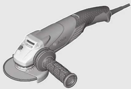
Product Features
The numbering of the product features refers to the illustration of the machine on the graphics page.
1 Release lever for protection guard
2 Spindle lock button
3 Thumbwheel for speed preselection (GWS 18-125 SL/GWS 18-125 SPL)
4 On/Off switch
5 Auxiliary handle (insulated gripping surface)
6 Grinder spindle
7 Extraction hood for sanding*
8 Mounting flange with O-ring
9 Carbide grinding head*
10 Clamping nut
11 Quick-clamping nut *SDS-clic
12 Protection guard for grinding
13 Grinding wheel*
14 Protection guard for cutting*
15 Cutting disc*
16 Hand guard*
17 Rubber sanding plate*
18 Sanding sheet*
19 Round nut*
20 Cup brush*
21 Cutting guide with dust extraction protection guard *
22 Diamond cutting disc*
23 Handle (insulated gripping surface)
24 Direction-of-rotation arrow for grinding spindle
25 Diamond core cutter*
*Accessories shown or described are not part of the standard delivery scope of the product. A complete overview of accessories can be found in our accessories program.
Technical Data
| Angle Grinder | GWS ... | 18-125 L | 18-125 PL | 18-125 SL | 18-125 SPL |
| Article number | 3 601 ... GA3 0.. GA3 1.. GA3 2.. GA3 3.. | ||||
| Rated power input | W | 1800 | 1800 | 1800 | 1800 |
| Output power | W | 1145 | 1145 | 1145 | 1145 |
| Rated speed | min^-1 | 12000 | 12000 | 12000 | 12000 |
| Speed control adjustment | min^-1 | - | - | 2800 - 12000 | 2800 - 12000 |
| Grinding disc diameter, max. | mm | 125 | 125 | 125 | 125 |
| Thread of grinder spindle | M 14 | M 14 M 14 | M 14 | ||
| Thread length (max.) of grinder spindle | mm | 22 | 22 | 22 | 22 |
| Kickback stop | ● | ● | ● | ● | |
| Restarting Protection | ● | ● | ● | ● | |
| Reduced starting current | ● | ● | ● | ● | |
| Constant electronic control | ● | ● | ● | ● | |
| Speed preselection | - | - | ● | ● | |
| The values given are valid for a nominal voltage [U] of 230 V. For different voltages and models for specific countries, these values can vary. | |||||
English | 21
| Angle Grinder | GWS ... | 18-125 L | 18-125 PL | 18-125 SL | 18-125 SPL |
| Weight according to EPTA-Procedure 01:2014 | |||||
| – with vibration-damping auxiliary handle | kg | 2.5 | 2.5 | 2.5 | 2.5 |
| – with standard-auxiliary handle | kg | 2.3 | 2.3 | 2.3 | 2.3 |
| Protection class | ☐/II | ☐/II | ☐/II | ☐/II | |
The values given are valid for a nominal voltage [U] of 230 V. For different voltages and models for specific countries, these values can vary.
| Angle Grinder | GWS ... | 18-125 L Inox | 18-125 PL Inox | 18-150 L | 18-150 PL |
| Article number | 3 601 ... | GA4 0.. | GA4 1.. | GA5 0.. | GA5 1.. |
| Rated power input | W | 1800 | 1800 | 1800 | 1800 |
| Output power | W | 1145 | 1145 | 1145 | 1145 |
| Rated speed | min^-1 | 8100 | 8100 | 10000 | 10000 |
| Speed control adjustment | min^-1 | - | - | - | - |
| Grinding disc diameter, max. | mm | 125 | 125 | 150 | 150 |
| Thread of grinder spindle | M 14 | M 14 | M 14 | M 14 | |
| Thread length (max.) of grinder spindle | mm | 22 | 22 | 22 | 22 |
| Kickback stop | ● | ● | ● | ● | |
| Restarting Protection | ● | ● | ● | ● | |
| Reduced starting current | ● | ● | ● | ● | |
| Constant electronic control | ● | ● | ● | ● | |
| Speed preselection | - | - | - | - | |
| Weight according to EPTA-Procedure 01:2014 | |||||
| - with vibration-damping auxiliary handle | kg | 2.5 | 2.5 | 2.5 | 2.5 |
| - with standard-auxiliary handle | kg | 2.3 | 2.3 | 2.4 | 2.4 |
| Protection class | ☐/II | ☐/II | ☐/II | ☐/II | |
The values given are valid for a nominal voltage [U] of 230 V. For different voltages and models for specific countries, these values can vary.
Noise/Vibration Information
| GWS ... | 18-125 L | 18-125 PL | 18-125 SL | 18-125 SPL | |
| 3 601 ... | GA3 0.. | GA3 1.. | GA3 2.. | GA3 3.. | |
| Sound emission values determined according to EN 60745-2-3. | |||||
| Typically the A-weighted noise levels of the product are | |||||
| Sound pressure level | dB(A) | 89 | 89 | 89 | 89 |
| Sound power level | dB(A) | 100 | 100 | 100 | 100 |
| Uncertainty K | dB | 3 | 3 | 3 | 3 |
| Wear hearing protection! | |||||
| Vibration total values a_h (triax vector sum) and uncertainty K determined according to EN 60745-2-3: | |||||
| Surface grinding: | |||||
| a_h | m/s2 | 10.0 | 10.0 | 10.0 | 10.0 |
| K | m/s2 | 1.5 | 1.5 | 1.5 | 1.5 |
| Disk sanding: | |||||
| a_h | m/s2 | 4.0 | 4.0 | 4.0 | 4.0 |
| K | m/s2 | 1.5 | 1.5 | 1.5 | 1.5 |
22 | English
3 601 ... GA4 0.. GA4 1.. GA5 0.. GA5 1..
Sound emission values determined according to EN 60745-2-3.
Typically the A-weighted noise levels of the product are
| Sound pressure level | dB(A) | 88 | 88 | 90 | 90 |
| Sound power level | dB(A) | 99 | 99 | 101 | 101 |
| Uncertainty K | dB | 3 | 3 | 3 | 3 |
Wear hearing protection!
Vibration total values a_h (triax vector sum) and uncertainty K determined according to EN 60745-2-3:
Surface grinding:
| a_h | m/s2 | 6.0 | 6.0 | 12.0 | 12.0 |
| K | m/s2 | 1.5 | 1.5 | 1.5 | 1.5 |
| Disk sanding: | |||||
| a_h | m/s2 | 3.0 | 3.0 | 3.0 | 3.0 |
| K | m/s2 | 1.5 | 1.5 | 1.5 | 1.5 |
The vibration level given in this information sheet has been measured in accordance with a standardised test given in EN 60745 and may be used to compare one tool with another. It may be used for a preliminary assessment of exposure.
The declared vibration emission level represents the main applications of the tool. However if the tool is used for different applications, with different accessories or insertion tools or is poorly maintained, the vibration emission may differ. This may significantly increase the exposure level over the total working period.
An estimation of the level of exposure to vibration should also take into account the times when the tool is switched off or when it is running but not actually doing the job. This may significantly reduce the exposure level over the total working period.
Identify additional safety measures to protect the operator from the effects of vibration such as: maintain the tool and the accessories, keep the hands warm, organisation of work patterns.
Assembly
Mounting the Protective Devices
▶ Before any work on the machine itself, pull the mains plug.
Note: After breakage of the grinding disc during operation or damage to the holding fixtures on the protection guard/power tool, the machine must promptly be sent to an after-sales service agent for maintenance. For addresses, see section "After-sales Service and Application Service".
Protection Guard for Grinding
Place the protection guard 12 on-to the spindle collar as shown in the illustration. The triangle marks on the protection guard must correspond with the respective marks on the gear case.
Press the protection guard 12 on-to the spindle collar until the shoulder of the protection guard is seated against the flange of the machine, and turn the protection guard until it can clearly be heard to engage.
Adjust the position of the protection guard 12 to the requirements of the work process. For this, press the release lever 1 upward and turn the protection guard 12 to the required position.
▶ Adjust the protection guard 12 in such a manner that sparking is prevented in the direction of the operator.
The protection guard 12 may be turned only upon actuation of the release lever 1! Otherwise the power tool may not continue to be used under any circumstances and must be taken to an after-sales service agent.
Note: The encoding keys on the protection guard 12 ensure that only a protection guard that fits the machine type can be mounted.
Protection Guard for Cutting
▶ For cutting with bonded abrasives, always use the protection guard for cutting 14.
▶ Provide for sufficient dust extraction when cutting stone.
The protection guard for cutting 14 is mounted in the same manner as the protection guard for grinding 12.
English | 23
Cutting Guide with Dust Extraction Protection Guard
The cutting guide with dust extraction protection guard 21 is mounted in the same manner as the protection guard for grinding 12.
Extraction Hood for Sanding
The extraction hood 7 can be used for low-dust sanding of paint, varnish and plastics in conjunction with the carbide grinding head 9 or the rubber sanding plate 17 with a sanding sheet 18. The extraction hood 7 is not suitable for working metals.
A suitable Bosch vacuum cleaner can be connected to the extraction hood 7.
The extraction hood 7 is mounted in the same manner as the protection guard 12. The brush collar is exchangeable.
Auxiliary Handle
▶ Operate your machine only with the auxiliary handle 5.
Screw the auxiliary handle 5 on the right or left of the machine head depending on the working method.
Hand Guard
For operations with the rubber sanding plate 17 or with the cup brush/wheel brush/flap disc, always mount the hand guard 16.
The hand guard 16 is fastened with the auxiliary handle 5.
Mounting the Grinding Tools
▶ Before any work on the machine itself, pull the mains plug.
▶ Do not touch grinding and cutting discs before they have cooled down. The discs can become very hot while working.
Clean the grinder spindle 6 and all parts to be mounted.
For clamping and loosening the grinding tools, lock the grinder spindle with the spindle lock button 2.
- Actuate the spindle lock button only when the grinder spindle is at a standstill. Otherwise, the machine may become damaged.
Grinding/Cutting Disc
Pay attention to the dimensions of the grinding tools. The mounting hole diameter must fit the mounting flange without play. Do not use reducers or adapters.
When using diamond cutting discs, pay attention that the direction-of-rotation arrow on the diamond cutting disc and the direction of rotation of the machine (see direction-of-rotation arrow on the machine head) agree.
See graphics page for the mounting sequence.
To fasten the grinding/cutting disc, screw on the clamping nut 10 and tighten with the two-pin spanner; see Section "Quick-clamping Nut".
▶ After mounting the grinding tool and before switching on, check that the grinding tool is correctly mounted and that it can turn freely. Make sure that the grinding tool does not graze against the protection guard or other parts.
A plastic part (O-ring) is fitted around the centring collar of mounting flange 8. If the O-ring is missing or damaged, the mounting flange 8 must be replaced before resuming operation.
Flap Disc
▶ For operations with the flap disc, always mount the hand guard 16.
Rubber Sanding Plate
For operations with the rubber sanding plate 17, always mount the hand guard 16.
See graphics page for the mounting sequence.
Screw on the round nut 19 and tighten with the two-pin spanner.
Cup Brush/Disc Brush
For operations with the cup brush/wheel brush, always mount the hand guard 16.
See graphics page for the mounting sequence.
The cup brush/disc brush must be able to be screwed onto the grinder spindle until it rests firmly against the grinder spindle flange at the end of the grinder spindle threads. Tight-en the cup brush/disc brush with an open-end spanner.
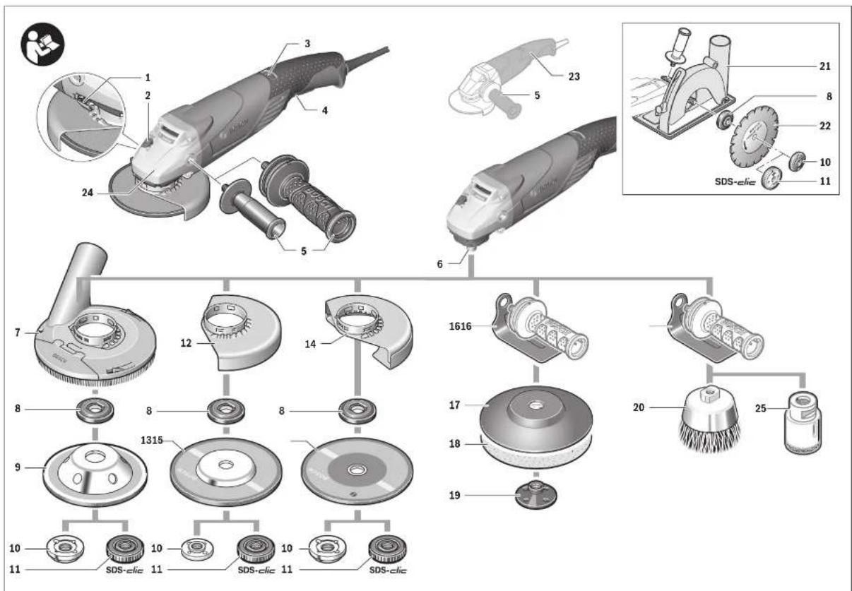
Quick-clamping Nut SDS-clic
For convenient changing of grinding tools without the use of additional tools, you can use the quick-clamping nut 11 instead of the clamping nut 10.
The quick-clamping nut 11 may be used only for grinding or cutting discs.
▶ Use only a flawless, undamaged quick-clamping nut 11.
When screwing on, pay attention that the side of the quick-clamping nut 11 with printing does not face the grinding disc; the arrow must point to the index mark 26.
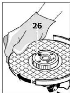
Lock the grinder spindle with the spindle lock button 2. To tighten the quick-clamping nut, firmly turn the grinding disc in clockwise direction.
24 | English
natural_image
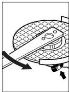
Diagram of a mechanical device with rotating components and directional arrows (no text or symbols)A properly attached, undamaged quick-clamping nut can be loosened by hand when turning the knurled ring in anticlockwise direction. Never loosen a tight quick-clamping nut with pliers. Always use the two-pin spanner. Insert the two-pin spanner as shown in the illustration.
Approved Grinding Tools
All grinding tools mentioned in these operating instructions can be used.
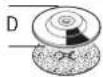
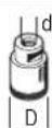
The permissible speed [min^-1] or the circumferential speed [m/s] of the grinding tools used must at least match the values given in the table.
Therefore, observe the permissible rotational/circumferential speed on the label of the grinding tool.
| max. [mm] D b d [min] | [mm] | -1] [m/s] | |||
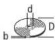 | 115 | 7 | 22.2 | 12000 | 80 |
| 125 | 7 | 22.2 | 12000 | 80 | |
| 150 | 7 | 22.2 | 10000 | 80 | |
 | 115 | - | - | 12000 | 80 |
| 125 | - | - | 12000 | 80 | |

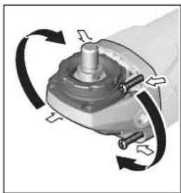
Rotating the Machine Head
▶ Before any work on the machine itself, pull the mains plug.
natural_image
Mechanical assembly diagram showing a rotating component with arrows indicating rotational direction (no text or symbols)The machine head can be rotated with respect to the machine housing in 90° steps. In this manner, the On/Off switch can be brought into a more convenient position for special working situations, e. g., for cutting operations using the cutting guide with dust extraction protection guard 21 or for left-handed persons.
Completely unscrew the four screws. Rotate the machine head carefully, without removing it from the housing, to the new position. Screw in and tighten the four screws again.
Dust/Chip Extraction
▶ Dust from materials such as lead-containing coatings, some wood types, minerals and metal can be harmful to one's health. Touching or breathing-in the dust can cause allergic reactions and/or lead to respiratory infections of the user or bystanders.
Certain dust, such as oak or beech dust, is considered carcinogenic, especially in connection with wood-treatment additives (chromate, wood preservative). Materials containing asbestos may only be worked by specialists.
- As far as possible, use a dust extraction system suitable for the material.
- Provide for good ventilation of the working place.
- It is recommended to wear a P2 filter-class respirator. Observe the relevant regulations in your country for the materials to be worked.
▶ Prevent dust accumulation at the workplace. Dust can easily ignite.
Operation
Starting Operation
▶ Observe correct mains voltage! The voltage of the power source must agree with the voltage specified on the nameplate of the machine. Power tools marked with 230 V can also be operated with 220 V.
Products sold in AUS and NZ only: Use a residual current device (RCD) with a rated residual current of 30 mA or less.
When operating the machine with power from mobile generators that do not have sufficient reserve capacity or are not equipped with suitable voltage control with starting current amplification, loss of performance or untypical behavior can occur upon switching on.
Please observe the suitability of the power generator being used, particularly with regard to the mains voltage and frequency.
English | 25
Switching On and Off
To save energy, only switch the power tool on when using it. To start the power tool, press the On/Off switch 4 forward and then down.
To lock-on the pressed On/Off switch 4, push the On/Off switch 4 further forward.
To switch off the power tool, release the On/Off switch 4, or when it is locked, briefly press the On/Off switch 4 and then release it.
Switch Version without Lock-on (country-specific):
To start the power tool, press the On/Off switch 4 forward and then down.
To switch off the machine, release the On/Off switch 4.
▶ Check grinding tools before using. The grinding tool must be mounted properly and be able to move freely. Carry out a test run for at least one minute with no load. Do not use damaged, out-of-centre or vibrating grinding tools. Damaged grinding tools can burst and cause injuries.
Kickback stop

In case of a sudden drop in speed, e.g., caused by a jammed disc while cutting, the power supply to the motor is electronically interrupted.
To restart the operation, switch the On/Off switch 4 to the Off position and start the machine again.
Restarting Protection
The restarting protection feature prevents uncontrolled re-starting of the machine after an interruption in the power supply.
To restart the operation, switch the On/Off switch 4 to the Off position and start the machine again.
Reduced starting current
The electronic reduced starting current limits the power consumption when switching the tool on and enables operation from a 13 ampere fuse.
Note: When the machine runs with full speed after switching on, the reduced starting current, the restarting protection and the kickback stop features have failed. The power tool must promptly be sent to an after-sales service agent for maintenance. For addresses, see Section „After-sales Service and Application Service“.
Constant Electronic Control
Constant electronic control holds the speed constant at no load and under load, and ensures uniform working performance.
Speed preselection (GWS 18-125 SL/GWS 18-125 SPL)
The required speed can be preselected with the thumbwheel 3 (also while running).
The data in the following table are recommended values.
Material Application Accessory Thumbwheel 3
| Metal Removing paint Sanding disc 2 – 3 | ||
| Wood, metal Brushing, rust removal Cup brush, sanding disc 3 | ||
| Metal, masonry Grinding Grinding disc 4 – 6 | ||
| Metal Rough grinding | Grinding disc 6 | |
| Masonry, stone Cutting | Cutting disc and cutting guide (Cutting masonry/stone is permitted only with use of the cutting guide) | 6 |
| Metal Cutting | Cutting disc | 6 |
The values specified for speed levels are guide values.
The rated speed of the accessory must be at least equal to the maximum speed marked on the power tool. Accessories running faster than their rated speed can break and fly apart.
| Speed prese-lection level | GWS 18-125 ... [min ^-1 ] | GWS 18-150 ... [min ^-1 ] |
| 1 | 2800 | 2800 |
| 2 | 4500 | 4100 |
| 3 | 6300 | 5400 |
| 4 | 8200 | 6700 |
| 5 | 9800 | 8000 |
| 6 | 12000 10000 |
Working Advice
Exercise caution when cutting slots in structural walls; see Section "Information on Structures".
▶ Clamp the workpiece if it does not remain stationary due to its own weight.
▶ Do not strain the machine so heavily that it comes to a standstill.
▶ After heavily straining the power tool, continue to run it at no-load for several minutes to cool down the accessory.
▶ Do not touch grinding and cutting discs before they have cooled down. The discs can become very hot while working.
▶ Do not use the power tool with a cut-off stand.
Bosch Power Tools 1 609 92A 3ZX | (7.11.17)
26 | English
Rough Grinding
▶ Never use a cutting disc for roughing.
The best roughing results are achieved when setting the machine at an angle of 30^ to 40^ . Move the machine back and forth with moderate pressure. In this manner, the workpiece will not become too hot, does not discolour and no grooves are formed.
Flap Disc
With the flap disc (accessory), curved surfaces and profiles can be worked.
Flap discs have a considerably higher service life, lower noise levels and lower sanding temperatures than conventional sanding sheets.
Cutting Metal
For cutting with bonded abrasives, always use the protection guard for cutting 14.
When cutting, work with moderate feed, adapted to the material being cut. Do not exert pressure onto the cutting disc, tilt or oscillate the machine.
Do not reduce the speed of running down cutting discs by applying sideward pressure.
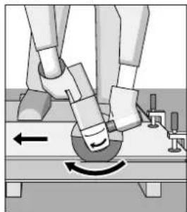
natural_image
Illustration of a robotic arm performing a circular motion on a surface, with no visible text or symbols.The machine must always work in an up-grinding motion. Otherwise, the danger exists of it being pushed un-controlled out of the cut.
When cutting profiles and square bar, it is best to start at the smallest cross section.
Cutting Stone
▶ Provide for sufficient dust extraction when cutting stone.
▶ Wear a dust respirator.
The machine may be used only for dry cutting/grinding.
For cutting stone, it is best to use a diamond cutting disc.
When using the cutting guide with dust extraction protection guard 21, the vacuum cleaner must be approved for vacuuming masonry dust. Suitable vacuum cleaners are available from Bosch.
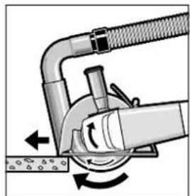
natural_image
Mechanical diagram showing a pipe joint with rotating components and directional arrows (no text or symbols)Switch on the machine and place the front part of the cutting guide on the workpiece. Slide the machine with moderate feed, adapted to the material to be worked.
For cutting especially hard material, e. g., concrete with high pebble content, the diamond cutting disc can overheat and become damaged as a result. This is clearly indicated by circular sparking, rotating with the diamond cutting disc. In this case, interrupt the cutting process and allow the diamond cutting disc to cool by running the machine for a short time at maximum speed with no load.
Noticeably decreasing work progress and circular sparking are indications of a diamond cutting disc that has become dull. Briefly cutting into abrasive material (e.g. lime-sand brick) can resharpen the disc again.
Information on Structures
Slots in structural walls are subject to the Standard DIN 1053 Part 1, or country-specific regulations.
These regulations are to be observed under all circumstances. Before beginning work, consult the responsible structural engineer, architect or the construction supervisor.
Maintenance and Service
Maintenance and Cleaning
▶ Before any work on the machine itself, pull the mains plug.
For safe and proper working, always keep the machine and ventilation slots clean.
In extreme conditions, always use dust extraction as far as possible. Blow out ventilation slots frequently and install a portable residual current device (PRCD). When working metals, conductive dust can settle in the interior of the power tool. The total insulation of the power tool can be impaired.
If the replacement of the supply cord is necessary, this has to be done by Bosch or an authorized Bosch service agent in order to avoid a safety hazard.
Please store and handle the accessory(-ies) carefully.
After-sales Service and Application Service
Our after-sales service responds to your questions concerning maintenance and repair of your product as well as spare parts. Exploded views and information on spare parts can also be found under:
www.bosch-pt.com
Bosch's application service team will gladly answer questions concerning our products and their accessories.
Français | 27
In all correspondence and spare parts orders, please always include the 10-digit article number given on the nameplate of the product.
Great Britain
Robert Bosch Ltd. (B.S.C.)
P.O. Box 98
Broadwater Park
North Orbital Road
Denham
Uxbridge
UB 9 5HJ
At www.bosch-pt.co.uk you can order spare parts or arrange the collection of a product in need of servicing or repair.
Tel. Service: (0344) 7360109
E-Mail: boschservicecentre@bosch.com
Ireland
Origo Ltd.
Unit 23 Magna Drive
Magna Business Park
City West
Dublin 24
Tel. Service: (01) 4666700
Fax: (01) 4666888
Australia, New Zealand and Pacific Islands
Robert Bosch Australia Pty. Ltd.
Power Tools
Locked Bag 66
Clayton South VIC 3169
Customer Contact Center
Inside Australia:
Phone: (01300) 307044
Fax: (01300) 307045
Inside New Zealand:
Phone: (0800) 543353
Fax: (0800) 428570
Outside AU and NZ:
Phone: +61 3 95415555
www.bosch-pt.com.au
www.bosch-pt.co.nz
Republic of South Africa
Customer service
Hotline: (011) 6519600
Gauteng - BSC Service Centre
35 Roper Street, New Centre
Johannesburg
Tel.: (011) 4939375
Fax: (011) 4930126
E-Mail: bsctools@icon.co.za
KZN - BSC Service Centre
Unit E, Almar Centre
143 Crompton Street
Pinetown
Tel.: (031) 7012120
Fax: (031) 7012446
E-Mail: bsc.dur@za.bosch.com
Western Cape - BSC Service Centre
Democracy Way, Prosperity Park
Milnerton
Tel.: (021) 5512577
Fax: (021) 5513223
E-Mail: bsc@zsd.co.za
Bosch Headquarters
Midrand, Gauteng
Tel.: (011) 6519600
Fax: (011) 6519880
E-Mail: rbsa-hq.pts@za.bosch.com
Disposal
The machine, accessories and packaging should be sorted for environmental-friendly recycling.

Do not dispose of power tools into household
waste!
Only for EC countries:
According to the European Directive 2012/19/EU for Waste Electrical and Electronic Equipment and its implementation into national right, power tools that are no longer usable must be collected separately and disposed of in an environmentally correct manner.
Subject to change without notice.
Français
natural_image
Diagram showing two mechanical or fluid dynamics states with directional arrows and control points (no text or symbols)natural_image
Mechanical diagram showing a cutting tool interacting with a circular component, with directional arrows indicating motion (no text or symbols)natural_image
Mechanical component with rotating arrows indicating rotational motion (no text or symbols)natural_image
Illustration of a robotic arm performing a circular motion on a surface, with no visible text or symbols.natural_image
Mechanical diagram showing a pipe joint with rotating components and directional arrows (no text or symbols)Robert Bosch (France) S.A.S.
natural_image
Diagram showing two circular mechanical components with directional arrows indicating rotation or force (no text or symbols)natural_image
Diagram of a mechanical device with rotating components and directional arrows (no text or symbols)natural_image
Mechanical assembly diagram showing a rotating component with arrows indicating rotational direction (no text or symbols)natural_image
Illustration of a robotic arm interacting with a circular component, showing motion direction (no text or symbols)natural_image
Mechanical diagram showing a pipe joint with rotating components and directional arrows (no text or symbols)natural_image
Diagram showing two circular mechanical components with directional arrows, no text or symbols presentnatural_image
Mechanical diagram showing a tool interacting with a circular component, no text or symbols presentnatural_image
Mechanical component with rotational arrows indicating motion (no text or symbols)natural_image
Illustration of a robotic arm interacting with a circular component, showing motion direction (no text or symbols)natural_image
Diagram of a mechanical device with rotating components and directional arrows (no text or symbols)natural_image
Diagram showing two mechanical or fluid dynamics states with directional arrows and control symbols (no text or labels)natural_image
Mechanical diagram showing a rotating tool interacting with a circular component (no text or symbols)natural_image
Mechanical component with rotating arrows indicating rotational motion (no text or symbols)natural_image
Diagram of a robotic arm interacting with a circular component, showing motion direction (no text or symbols)natural_image
Mechanical diagram showing a pipe joint with rotating components and directional arrows (no text or symbols)natural_image
Diagram showing two mechanical or fluid dynamics setups with rotating components and directional arrows (no text or symbols)Snelspanmoer SDS-clic
natural_image
Mechanical diagram showing a rotating tool interacting with a circular component (no text or symbols)natural_image
Mechanical component with rotating arrows indicating rotational motion (no text or symbols)natural_image
Illustration of a robotic arm performing a circular motion maneuver on a surface (no text or symbols)natural_image
Mechanical diagram showing a pipe joint with rotating components and directional arrows (no text or symbols)natural_image
Diagram showing two mechanical or fluid dynamics setups with rotating components and directional arrows (no text or symbols)natural_image
Diagram of a mechanical device with rotating components and directional arrows (no text or symbols)natural_image
Mechanical component with rotating arrows indicating rotational motion (no text or symbols)natural_image
Illustration of a robotic arm performing a circular motion maneuver with a curved arrow (no text or symbols)natural_image
Diagram of a mechanical device with hoses and rotating components (no text or symbols)Bosch Service Center
Telegrafvej 3
2750 Ballerup
På www.bosch-pt.dk kan der online bestilles reservedele eller oprettes en reparations ordre.
Tlf. Service Center: 44898855
Fax: 44898755
E-Mail: vaerktoej@dk.bosch.com
Bortskaffelse
natural_image
Diagram showing two mechanical or fluid dynamics states with rotating components and directional arrows (no text or symbols)natural_image
Mechanical diagram showing a rotating tool interacting with a circular component (no text or symbols)natural_image
Mechanical component with rotating arrows indicating motion (no text or symbols)natural_image
Illustration of robotic arm positioning on a platform with motion arrows (no text or symbols)natural_image
Mechanical diagram showing a pipe joint with rotating components and directional arrows (no text or symbols)Bosch Service Center
Telegrafvej 3
2750 Ballerup
Danmark
Tel.: (08) 7501820 (inom Sverige)
Fax: (011) 187691
Avfallshantering
natural_image
Diagram showing two circular mechanical components with directional arrows, no text or symbols presentSett vernedekselet 12 på spindelhalsen som vist på bildet. Trekantmarkeringene på vernedekselet må stemme overens med de tilsvarende markeringene på girho-det.
natural_image
Diagram of a mechanical device with rotating components and directional arrows (no text or symbols)natural_image
Mechanical assembly diagram showing a rotating component with arrows indicating rotational motion (no text or symbols)natural_image
Illustration of a robotic arm performing a circular motion on a surface, with no visible text or symbols.natural_image
Mechanical diagram showing a pipe joint with rotating components and directional arrows (no text or symbols)natural_image
Diagram showing two circular components with directional arrows and internal symbols, no readable text or labelsnatural_image
Mechanical diagram showing a rotating tool interacting with a circular component (no text or symbols)natural_image
Mechanical component diagram showing rotational motion with arrows indicating direction (no text or symbols)natural_image
Illustration of a robotic arm performing a circular motion maneuver with directional arrows (no text or symbols)natural_image
Mechanical diagram showing a pipe joint with rotating components and directional arrows (no text or symbols)natural_image
Diagram showing two circular mechanical components with directional arrows and internal symbols, no readable text or labels present.natural_image
Mechanical diagram showing a tool interacting with a meshed circular component, no text or symbols presentnatural_image
Mechanical component with rotating arrows indicating rotational motion (no text or symbols)natural_image
Illustration of a robotic arm performing a circular motion on a surface, with no visible text or symbols.natural_image
Diagram of a mechanical device with rotating components and directional arrows indicating motion (no text or symbols)natural_image
Two circular diagrams showing directional arrows and internal structures, no text or symbols presentnatural_image
Diagram of a mechanical device with rotating components and directional arrows (no text or symbols)natural_image
Mechanical component with rotating arrows indicating rotational motion (no text or symbols)natural_image
Illustration of a robotic arm performing a circular motion maneuver on a surface, with no visible text or symbols.natural_image
Mechanical diagram showing a pipe clamp and valve mechanism with directional arrows (no text or symbols)natural_image
Two diagrams showing mechanical or fluid dynamics with arrows indicating rotational motion (no text or symbols)natural_image
Diagram of a mechanical device with rotating components and directional arrows (no text or symbols)natural_image
Mechanical component with rotating arrows indicating rotational motion (no text or symbols)natural_image
Illustration of a robotic arm performing a circular motion on a surface, with no visible text or symbols.natural_image
Mechanical diagram showing a pipe joint with rotating components and directional arrows (no text or symbols)Robert Bosch Sp. z o.o.
natural_image
Diagram showing two circular mechanical components with directional arrows indicating rotation or force (no text or symbols)natural_image
Diagram of a mechanical device with rotating components and directional arrows (no text or symbols)natural_image
Mechanical component with rotational arrows indicating motion (no text or symbols)natural_image
Illustration of robotic arm positioning on a surface with motion arrows (no text or symbols)natural_image
Diagram of a mechanical device with rotating components and directional arrows (no text or symbols)Bosch Service Center PT
K Vápence 1621/16
692 01 Mikulov
natural_image
Diagram showing two circular mechanical components with directional arrows, no text or symbols presentnatural_image
Diagram of a mechanical device with rotating components and directional arrows (no text or symbols)natural_image
Mechanical component with rotating arrows indicating rotational motion (no text or symbols)natural_image
Illustration of robotic arm positioning on a platform with directional arrows indicating movement (no text or symbols)natural_image
Mechanical diagram showing a pipe joint with rotating components and directional arrows (no text or symbols)natural_image
Diagram showing two circular components with directional arrows and internal symbols, no readable text or labelsnatural_image
Diagram of a mechanical device with rotating components and directional arrows (no text or symbols)natural_image
Mechanical component with rotating arrows indicating rotational motion (no text or symbols)natural_image
Illustration of a robotic arm performing a circular motion maneuver on a surface (no text or symbols)natural_image
Mechanical diagram showing a pipe joint with rotating components and directional arrows (no text or symbols)natural_image
Two diagrams showing mechanical or fluid dynamics with arrows indicating rotation and movement, no text or symbols present.natural_image
Mechanical diagram showing a rotating tool interacting with a circular component (no text or symbols)natural_image
Mechanical component with rotational arrows indicating motion (no text or symbols)natural_image
Illustration of a robotic arm performing a circular motion on a surface, with no visible text or symbols.natural_image
Mechanical diagram showing a pipe joint with rotating components and directional arrows (no text or symbols)natural_image
Two diagrams showing a rotating mechanical component with directional arrows, no text or symbols present.natural_image
Diagram of a mechanical device with rotating components and directional arrows (no text or symbols)natural_image
Mechanical component with rotating arrows indicating rotational motion (no text or symbols)natural_image
Illustration of a robotic arm performing a circular motion on a surface, with no visible text or symbols.natural_image
Mechanical diagram showing a pipe joint with rotating components and directional arrows (no text or symbols)natural_image
Diagram showing two circular components with directional arrows and internal structures, no text or symbols present.natural_image
Diagram of a mechanical device with rotating components and directional arrows (no text or symbols)natural_image
Mechanical component with rotating arrows indicating rotational motion (no text or symbols)natural_image
Illustration of a robotic arm performing a circular motion maneuver on a surface, with no visible text or symbols.natural_image
Mechanical diagram showing a pipe joint with rotating components and directional arrows (no text or symbols)natural_image
Diagram showing two mechanical or fluid dynamics states with directional arrows and circular components (no text or symbols)natural_image
Mechanical diagram showing a rotating tool interacting with a meshed circular component (no text or symbols)natural_image
Mechanical component with rotating arrows indicating rotational motion (no text or symbols)natural_image
Illustration of a robotic arm performing a motion maneuver with a curved arrow indicating rotational motion (no text or symbols present)natural_image
Diagram of a mechanical device with rotating arm and pipe fitting (no text or symbols)Service scule electrice
Strada Horia Măcelariu Nr. 30-34, sector 1
013937 Bucureşti
natural_image
Diagram showing two circular mechanical components with directional arrows, no text or symbols presentnatural_image
Diagram of a mechanical device with rotating components and directional arrows (no text or symbols)natural_image
Mechanical component with rotating arrows indicating rotational motion (no text or symbols)natural_image
Illustration of a robotic arm performing a circular motion maneuver on a surface, with no visible text or symbols.natural_image
Mechanical diagram showing a pipe joint with rotating components and directional arrows (no text or symbols)Service scule electrice
Strada Horia Măcelariu Nr. 30-34, sector 1
013937 Bucureşti, România
www.bosch-pt.com/bg/bg/
Македонски | 251
Бракуване
natural_image
Diagram showing two circular mechanical components with directional arrows, no text or symbols presentnatural_image
Diagram of a mechanical device with rotating components and directional arrows (no text or symbols)natural_image
Mechanical component with rotating arrows indicating rotational motion (no text or symbols)natural_image
Illustration of a robotic arm performing a circular motion on a surface, with no visible text or symbols.natural_image
Mechanical diagram showing a pipe clamp and rotating wheel mechanism (no text or symbols)natural_image
Diagram showing two circular components with directional arrows and internal symbols, no readable text or labels present.Postavite zaštitnu haubu 12 prema slici na vrat vretena. Trouglaste oznake zaštitne haube moraju biti usaglašene sa odgovarajućim oznakama na glavi prenosnika. Pritiskajte zaštitnu haubu 12 sve dok venac zaštitne haube ne nalegne na prirubnicu električnog alata i okrećite zaštitnu haubu sve dok jasno i da se čuje ne uskoči. Prilagodite poziciju zaštitne haube 12 potrebama rada.
Pritisnite za to polugu za deblokadu 1 na gore i okrenite zaštitnu haubu 12 u željenu poziciju.
▶ Podesite zaštitnu haubu 12 tako, da se spreči letenje varnica u pravcu radnika.
Zaštitna hauba 12 sme se okretati samo aktiviranjem poluge za deblokadu 1! U drugom slučaju nesme se nikako električni alat koristiti dalje i mora se predati u servis.
Pažnja: Ispusti za kodiranje na zaštitnoj haubi 12 obezbedjuju, da se može montirati samo jedna zaštitna hauba koja odgovara električnom alatu.
Zaštitna hauba za presecanje
natural_image
Diagram of a mechanical device with rotating components and directional arrows (no text or symbols)Jednu propisno učvršćenu, neošćetenju navrtku sa brzim zatezanjem možete rukom odvrnuti okretanjem nareckanog prstena nasuprot smeru kazaljke na satu.
Ne odvrćite čvrsto stegnutu navrtku sa brzim stezanjem sa kleštama, već koristite ključ sa dva otvora. Upotrebljavajte ključ kao što slika pokazuje.
Dozvoljeni alati za brušenje
Možete koristiti sve alate za brušenje navedene u ovom uputstvu za rad.
natural_image
Mechanical component with rotating arrows indicating rotational motion (no text or symbols)Možete glavu prenosnika okretati u 90° podeoka. Na taj način se prekidač za uključivanje-isključivanje za posebne radne slučajeve dovodi u povoljniju poziciju za rukovanje, na primer za radove presecanja sa usisavajućom haubom sa klizajućom vodjicom 21 ili za levoruke.
Odvrnite sasvim 4 zavrtnja. Oprezno iskrenite glavu prenosnika u novu poziciju ne skidajući sa kućišta. Ponovo stegnite 4 zavrtnja.
Usisavanje prašine/piljevine
▶ Prašine od materijala kao što je premaz koji sadrži olovo, neke vrste drveta, minerali i metal mogu biti štetni po zdravlje. Dodir ili udisanje prašine mogu izazvati alergijske reakcije i/ili oboljenja disajnih puteva radnika ili osoba koje se nalaze u blizini.
Neke prašine kao od hrasta i bukve važe kao izazivači raka, posebno u vezi sa dodatnim materijama za obradu drveta (hromati, zaštitna sredstva za drvo). Materijal koji sadrži azbest smeju raditi samo stručnjaci.
- Koristite što je više moguće usisavanje prašine pogodno za materijal.
- Pobrinite se za dobro provetravanje radnog mesta.
- Preporučuje se, da se nosi zaštitna maska za disanje sa klasom filtera P2.
natural_image
Illustration of a robotic arm performing a circular motion maneuver on a surface, with no visible text or symbols.natural_image
Mechanical diagram showing a pipe joint with rotating components and directional arrows (no text or symbols)natural_image
Diagram showing two mechanical or fluid dynamics setups with rotating components and directional arrows (no text or symbols)natural_image
Mechanical diagram showing a rotating tool interacting with a circular component (no text or symbols)natural_image
Mechanical component with rotating arrows indicating rotational motion (no text or symbols)natural_image
Illustration of a robotic arm performing a circular motion maneuver on a surface, with no visible text or symbols.natural_image
Mechanical diagram showing a pipe clamp and valve mechanism with directional arrows (no text or symbols)natural_image
Two circular diagrams showing mechanical or electrical components with directional arrows, no text or symbols present.Stavite štitnik 12 na rukavac vretena prema slici. Oznake trokuta štitnika moraju se podudarati sa odgovarajućim oznakama na glavi prijenosnika.
natural_image
Diagram of a mechanical device with rotating components and directional arrows (no text or symbols)natural_image
Mechanical assembly diagram showing a rotating component with arrows indicating rotational direction (no text or symbols)natural_image
Illustration of a robotic arm performing a circular motion on a surface, with no visible text or symbolsnatural_image
Mechanical diagram showing a pipe joint with rotating components and directional arrows (no text or symbols)natural_image
Diagram showing two mechanical or fluid dynamics states with directional arrows and circular components (no text or symbols)natural_image
Mechanical diagram showing a rotating tool interacting with a circular component (no text or symbols)natural_image
Mechanical component with rotating arrows indicating rotational motion (no text or symbols)natural_image
Illustration of a robotic arm interacting with a curved mechanical component (no text or symbols visible)natural_image
Diagram of a mechanical device with rotating arm and pipe, showing motion arrows (no text or symbols)Staatikaalased juhised
natural_image
Two diagrams showing a rotating mechanical component with directional arrows, no text or symbols present.natural_image
Diagram of a mechanical device with rotating components and directional arrows (no text or symbols)natural_image
Mechanical component with rotating arrows indicating motion (no text or symbols)natural_image
Illustration of a robotic arm performing a circular motion on a surface, with no visible text or symbols.natural_image
Mechanical diagram showing a pipe clamp and rotating valve mechanism (no text or symbols)natural_image
Diagram of a mechanical device with rotating components and directional arrows (no text or symbols)natural_image
Mechanical assembly diagram showing a rotating component with arrows indicating rotational motion (no text or symbols)natural_image
Illustration of a robotic arm performing a circular motion on a surface, with no visible text or symbols.natural_image
Mechanical diagram showing a pipe joint with rotating components and directional arrows (no text or symbols)natural_image
Diagram showing two circular components with directional arrows and internal symbols, no readable text or labelsnatural_image
Diagram of a mechanical device with rotating components and directional arrows (no text or symbols)natural_image
Mechanical component with rotating arrows indicating rotational motion (no text or symbols)natural_image
Illustration of a robotic arm performing a circular motion maneuver on a surface, with no visible text or symbols.natural_image
Mechanical diagram showing a pipe clamp and rotating saw (no text or symbols)Mechanics and Electronics Ltd. PT/SAX-ASA
298 Bojeong-dong Giheung-gu
Yongin-si, Gyeonggi-do, 446-913
080-955-0909
Central Motors & Equipment LLC
1984:البريد
Malatan Trading & Contracting LLC
131:البريد
سلطنة عمان
+968 99886794: هاتف
International Construction Solutions W L L
البريد: 51 الدوحة
قطر
+974 40065458: هاتف
+974 4453 8585:فاكس
natural_image
Illustration of a robotic arm performing a circular motion on a surface, with no visible text or symbols.IPL should be a "c" in the case of the case of the case of the case of the case of the case of the case of the case of the case of the case of the case of the case of the case of the case of the case of the case of the case of the case of the case of the case of the case of the case of the case of the case of the case of the case of the case of the case of the case of the case of the case of the case of the case of the case of
natural_image
Diagram of a mechanical device with rotating components and directional arrows indicating motion (no text or symbols)Correctional Privacy Policy: 1.1.1.1.1.1.1.1.1.1.1.1.1.1.1.1.1.1.1.1.1.1.1.1.1.1.1.1.1.1.1.1.1.1.1.1.1.1.1.1.1.1.1.1.1.1.1.1.1.1.1. The quick of the government's policy, and the implementation of the government's policies, is to be applied to the government's policy, and the implementation of the government's policies, is to be applied to the government's policies, and the implementation of the government's policies, is to be applied to the government's policies, and the implementation of the government's policies, is to be applied to the government's policies, and the implementation of the government's policies, is to be applied to the government's policies, and the implementation of the government's policies, is to be applied to the government's policies, and the implementation of the government's policies, is to be applied to the government's policies, and the implementation in this policy is provided by the Government Administration for the United States Department of Technology and Human Resources Administration (HRS).
natural_image
Mechanical assembly diagram showing a rotating component with springs and a central shaft (no text or symbols)11 youth should be interested in the school of the country.
natural_image
Mechanical diagram showing a rotating tool interacting with a meshed circular component, with directional arrows indicating motion (no text or symbols)natural_image
Technical diagram of a mechanical bearing assembly (no text or labels)قرص التجليغ المروحي
natural_image
Illustration of a robotic arm performing a circular motion on a surface, with no visible text or symbols.natural_image
Diagram of a mechanical device with rotating components and directional arrows indicating motion (no text or symbols)natural_image
Mechanical assembly diagram showing a rotating component with springs and a central shaft (no text or symbols)natural_image
Mechanical diagram showing a rotating tool interacting with a circular component, with directional arrows indicating motion (no text or symbols)natural_image
Technical diagram of a mechanical bearing assembly (no text or symbols)صفه سنباده پره ای
natural_image
Diagram showing two circular mechanical components with directional arrows indicating rotation or force (no text or symbols)


- GWS Professional
- BOSCH
- Deutsch
- Sicherheitshinweise
- General Power Tool Safety Warnings
- Save all warnings and instructions for future reference.
- Work area safety
- Electrical safety
- Personal safety
- Power tool use and care
- | English
- Service
- Safety Warnings for Angle Grinder
- Kickback and related warnings
- English | 19
- Safety warnings specific for Grinding and Abrasive Cutting-Off operations
- Additional safety warnings specific for abrasive cutting off operations
- Safety warnings specific for sanding operations
- Safety warnings specific for wire brushing operations
- Additional safety warnings
- Wear safety goggles.
- | English
- Product Description and Specifications
- Read all safety warnings and all instruc-
- Intended Use
- Product Features
- Wear hearing protection!
- Assembly
- Mounting the Protective Devices
- Protection Guard for Grinding
- Protection Guard for Cutting
- English | 23
- Cutting Guide with Dust Extraction Protection Guard
- Extraction Hood for Sanding
- Auxiliary Handle
- Hand Guard
- Mounting the Grinding Tools
- Grinding/Cutting Disc
- Flap Disc
- Rubber Sanding Plate
- Cup Brush/Disc Brush
- Quick-clamping Nut SDS-clic
- | English
- Approved Grinding Tools
- Rotating the Machine Head
- Dust/Chip Extraction
- Operation
- Starting Operation
- English | 25
- Switching On and Off
- Switch Version without Lock-on (country-specific):
- Kickback stop
- Restarting Protection
- Reduced starting current
- Constant Electronic Control
- Speed preselection (GWS 18-125 SL/GWS 18-125 SPL)
- Working Advice
- | English
- Rough Grinding
- Cutting Metal
- Cutting Stone
- Information on Structures
- Maintenance and Service
- Maintenance and Cleaning
- After-sales Service and Application Service
- www.bosch-pt.com
- Great Britain
- Ireland
- Australia, New Zealand and Pacific Islands
- Republic of South Africa
- Customer service
- Gauteng - BSC Service Centre
- KZN - BSC Service Centre
- Western Cape - BSC Service Centre
- Bosch Headquarters
- Disposal
- Only for EC countries:
- Français
- Snelspanmoer SDS-clic
- Bortskaffelse
- Avfallshantering
- Бракуване
- Zaštitna hauba za presecanje
- Dozvoljeni alati za brušenje
- Usisavanje prašine/piljevine
- Staatikaalased juhised
Brand : BOSCH
Model : GWS 18150 PL Professional
Category : Coffee grinder