KBKA 65 - Electric sander FESTOOL - Free user manual and instructions
Find the device manual for free KBKA 65 FESTOOL in PDF.
| Product type | Edge bander (KBKA 65 system) |
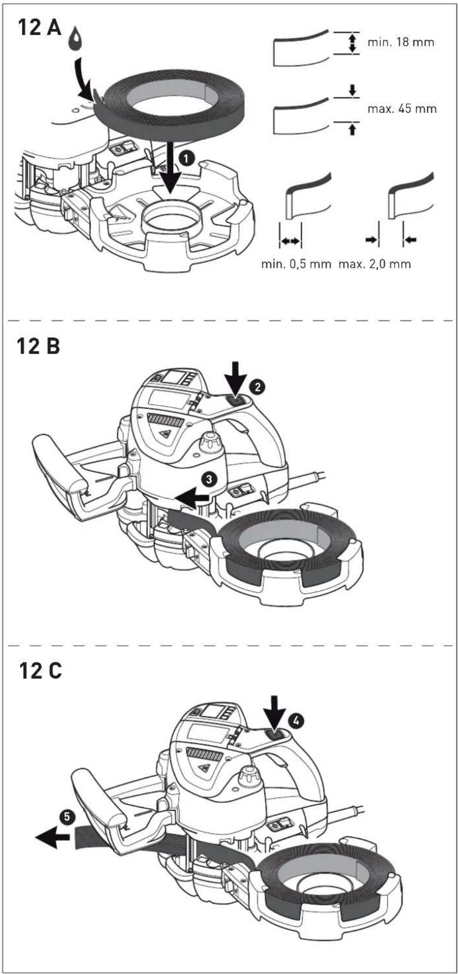
| Edge height | 18 - 65 mm |
| Edge thickness | 0.5 - 3.0 mm |
| Use | Cutting edge strips on right-angled and round workpieces |
| Feed | Manual |
| Safety | Sharp blade, read safety instructions |
| Maintenance | Blade replacement: unscrew screws, remove blades, insert new ones |
| Included accessories | Dispenser KSP-KA 65, auxiliary roller ZR-KA 65, scraper ZK-HW 45/45, guide plate LAS-STF-KA 65, polishing felt PF-STF 80x133, wood block HSK 80x133 H, polishing compound MPA 600, manual abrasive Brilliant 2 |
| Repairability | Use original Festool spare parts; repair by manufacturer or authorized workshop |
| Environment | Do not dispose of with household waste; comply with REACH regulations |
Frequently Asked Questions - KBKA 65 FESTOOL
User questions about KBKA 65 FESTOOL
0 question about this device. Answer the ones you know or ask your own.
Ask a new question about this device
Download the instructions for your Electric sander in PDF format for free! Find your manual KBKA 65 - FESTOOL and take your electronic device back in hand. On this page are published all the documents necessary for the use of your device. KBKA 65 by FESTOOL.
USER MANUAL KBKA 65 FESTOOL
natural_image
Collection of mechanical assembly components including a white FERTOL box, black clamps, and various colored sheets (no text or symbols visible)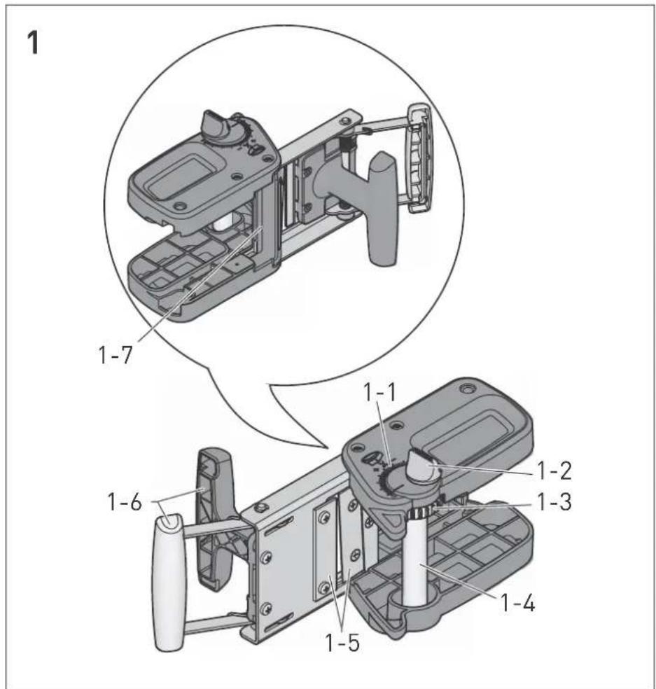
3
A
natural_image
Mechanical assembly diagram showing a piston and housing component with an upward arrow (no text or labels)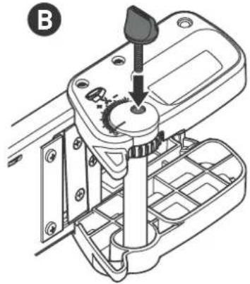
natural_image
Technical line drawing of a mechanical assembly with a tool inserted into a housing (no text or symbols)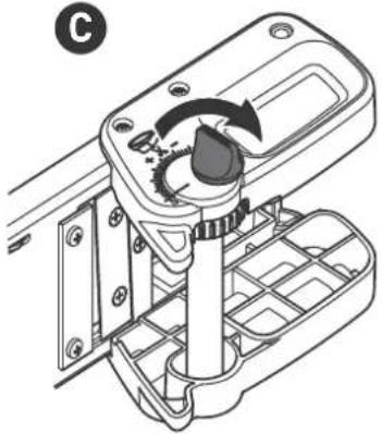
natural_image
Mechanical device with a rotary knob and internal grid structure (no text or symbols)D
natural_image
Technical diagram of a mechanical device with internal components and directional arrows indicating motion (no text or symbols)4
natural_image
Technical line drawing of a mechanical device with a close-up inset showing internal components (no text or symbols)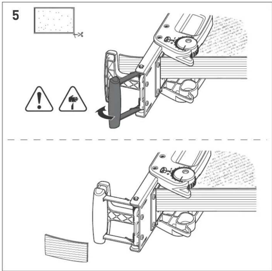
Original operating manual
1 S y m b o

Warning of general danger

Manual, read the instructions

Do not throw in the household waste.

Risk of injury from sharp blade

Machining rectangular workpieces

Machining round workpieces

Tip or advice
2 Scope of delivery
- Edge cutter KP 65/2 [Fig. 1 - 10]
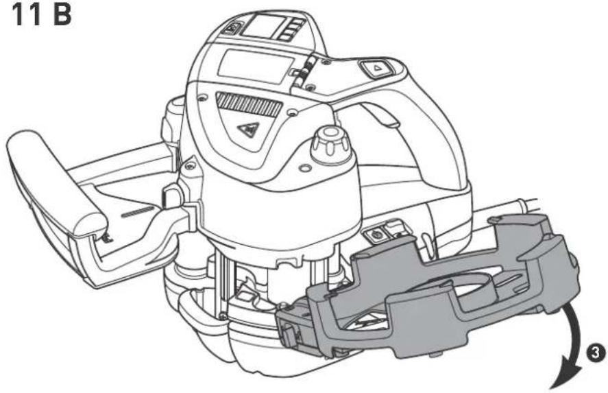
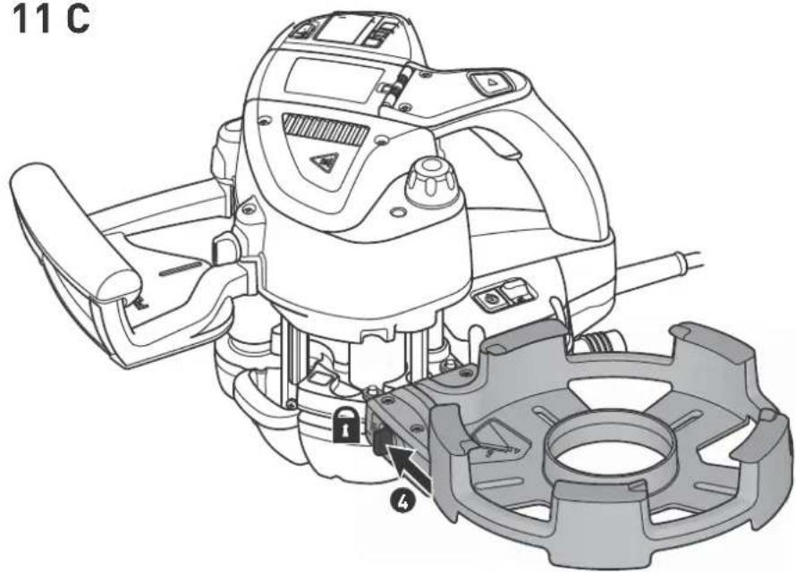
- Edge magazine KSP-KA 65 [Fig. 11 + 12]
- Additional roll ZR-KA 65 [Fig. 13]
- Scraper ZK-HW 45/45 [Fig. 14]
- Plastic sliding plate LAS-STF-KA 65 with scratch protector EF-LAS-STF-KA 65/3x [Fig. 15]
- Polishing felt PF-STF 80 x 133 STF-H/5x
- Hand sanding block HSK 80 x 133 H
- Polish MPA 600
- Hand abrasive Brilliant 2
3 General safety instructions
Warning! Read and observe all information and safety instructions. Ignoring warning notes and instructions may lead to electric shocks, fires and/or cause serious injury.
Keep all safety information and other instructions in a safe place for future reference.

The user is liable for improper or non-in-tended use.
4 Edge cutter KP 65/2
4.1 Intended use
The edge trimmer MFT/3 is specifically designed for trimming plastic edge bands on rectangular and round workpieces.
4.2 Technical data
Edge trimmer KP 65/2
* Depending on material
4.3 Machine features
[1-1] Edge length scale
[1-2] Rotary knob
[1-3] Edge length fine adjuster
[1-4] Stop pin
[1-5] Trimming fixture with blade
[1-4] Handles
[1-7] Internal stop
The specified illustrations appear at the beginning of the Operating Instructions.
4.4 Machine-related safety instructions
Warning! Read and observe all information and safety instructions. Ignoring warning notes and instructions may result in serious injuries from the sharp blade on the trimming fixture.
Keep all safety information and other instructions in a safe place for future reference.
4.5 Settings
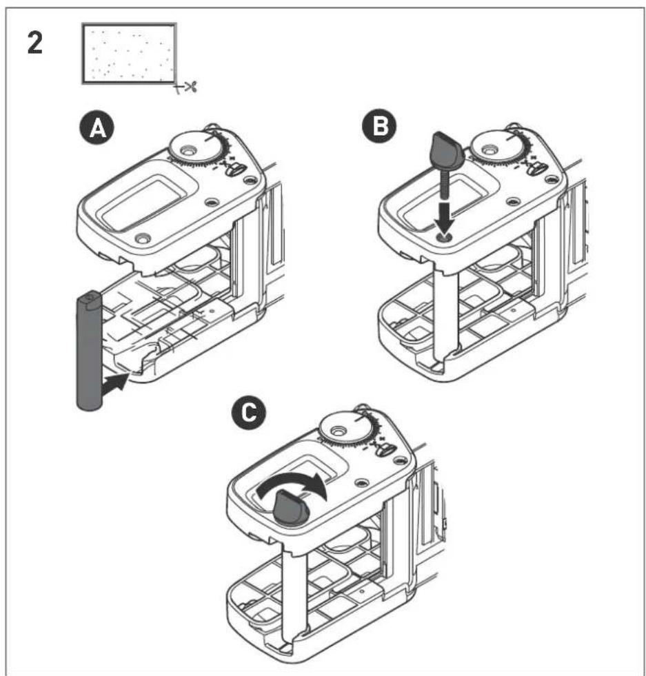
Fitting the stop pin for rectangular workpieces [2]
The stop pin [1-4] is located in this position when the machine is delivered.
▶ Insert the stop pin [1-4] into the rear recess on the edge trimmer [2 A].
▶ Insert the rotary knob [1-2] into the opening above the stop pin [1-4] [2 B].
▶ Tighten the rotary knob [1-2] by turning clockwise [2 C].
Disassembly
Removal in reverse order.
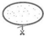
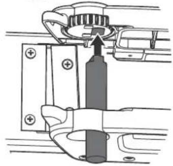
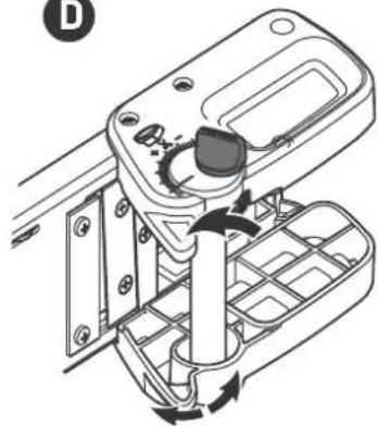
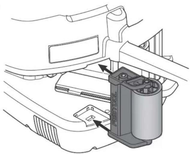
Fitting the stop pin for round workpieces [3]
▶ Insert the stop pin [1-4] into the recess under the fine adjuster for the trimming length [1-3] [3 A].
▶ Insert the rotary knob [1-2] into the opening above the stop pin [1-4] [3 B].
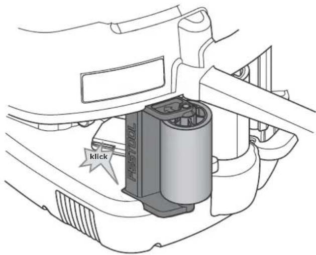
▶ Tighten the rotary knob [1-2] by turning clockwise [3 C].
▶ Slacken the rotary knob [1-2] by turning anticlockwise half a revolution so that the fine adjuster for the edge length [1-3] moves freely [3D].
Disassembly
Removal in reverse order.
i Series production: When machining several round workpieces with the same radius, the trimming fixture with blade [1-5] can be set to the same position for all edge bands.
▶ Edge band trimming process (see chapter Trimming edge bands on round workpieces).
▶ Tighten the rotary knob [1-2] before trimming the edge band.
The trimming fixture with blade [1-5] is now set and secured in the same position for all edge bands.
▶ Edge band trimming process (see chapter Trimming edge bands on round workpieces).
▶ Tighten the rotary knob [1-2] before trimming the edge band.
The trimming fixture with blade [1-5] is now set and secured in the same position for all edge bands.
4.6 Working with the machine
Trimming edge bands on rectangular workpieces
▶ Fit stop pin [1-4] for square workpieces (see chapter Fitting the stop pin for rectangular workpieces [2]).
▶ Slide the protruding edge band into the trimming fixture with blade [1-5] [4].
▶ Push the edge trimmer up to the stop pin [1-4] parallel with the workpiece [4].
▶ Push the handles [1-4] together and trim the edge band [5] .

Caution, sharp blade! Risk of injury! Keep fingers well away from the blade on the trimming fixture [1-5].
Trimming edge bands on round workpieces
▶ Fit stop pin [1-4] for round workpieces (see chapter Fitting the stop pin for round workpieces [3]).
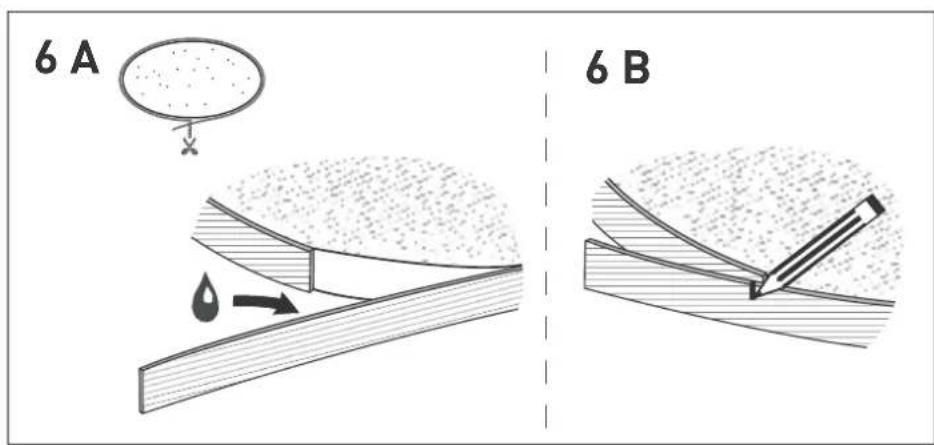
▶ Glue the edge band to the workpiece.
▶ Move the machine with the edge band away from the workpiece approx. 10 cm in front of the cutting point.
▶ Apply glue up to the cutting point and leave some space between the edge band and workpiece so that the edge band is not glued to the workpiece [6].
▶ Mark the cutting point on the edge band [6 B].
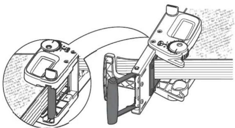
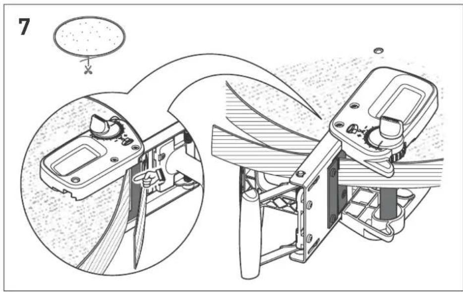
▶ Allow the protruding edge band to move over the stop pin [1-4] and slide into the trimming fixture with blade [1-5] [7].
▶ Push the edge trimmer from the front towards the workpiece up to the stop pin [1-4] until the glued edge band makes contact with the inner stop [1-7] [7].
▶ Move the edge trimmer so that the mark is positioned approximately in the trimming fixture with blade [1-5].
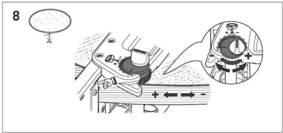
The fine adjuster for the edge length [1-3] can be used to adjust the edge band with the marking more accurately [8].
The edge length scale [1-1] indicates whether more or less of the edge band must be trimmed:
- Clockwise rotation: shorter edge band, more of the edge band is trimmed -
- Anticlockwise rotation: longer edge band, less of the edge band is trimmed +
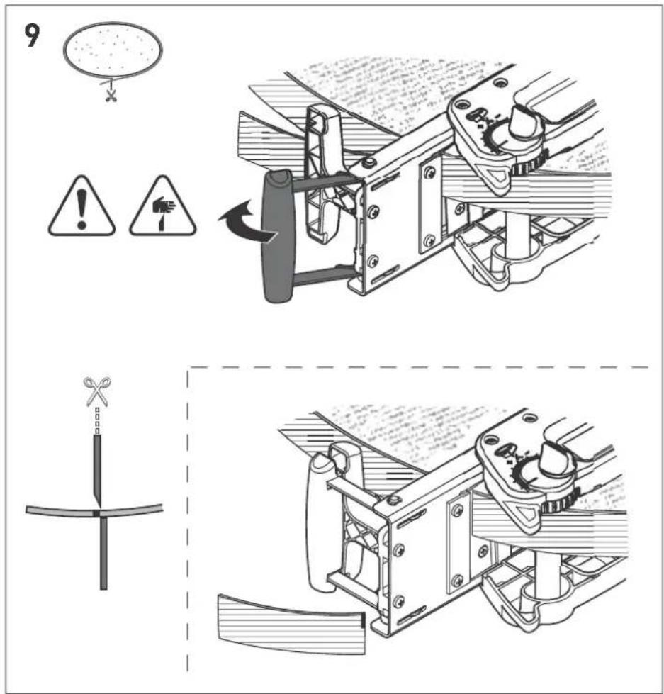
▶ If the marking is located directly behind the blade on the trimming fixture [1-5] , push the handles [1-4] together and trim the edge band [9] .

Caution, sharp blade! Risk of injury! Keep fingers well away from the blade on the trimming fixture [1-5].
▶ After trimming the workpiece, affix the edge band with adhesive to the workpiece using a hot air blower, for example.
4.7 Accessories
Trimming fixture with blade
The trimming fixture with blade [1-5] produces a clean, accurate cut.
- Always use sharp, undamaged blades.
- Replace blunt or damaged blades.
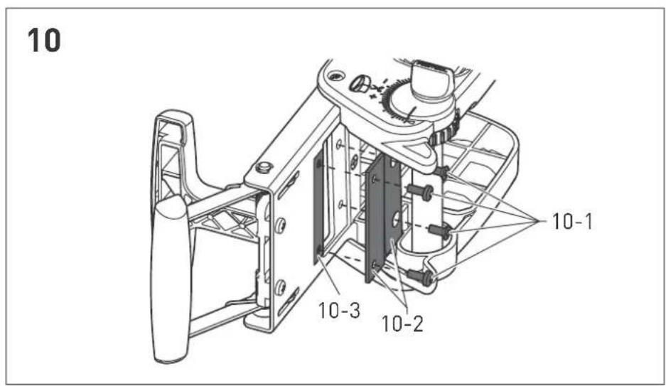
Changing blades [10]
▶ Slacken the screws using a cross-head screw-driver [10-1].
▶ Remove the blade [10-2].
▶ Keep the shims in position [10-3].
▶ Place the blade [10-2] over the shims [10-3].
▶ Tighten the screws using a cross-head screw-driver [10-1].
For the safe guidance of delicate and thin edging into the edge bander KA 65.
Safe guidance of long edges without damaging or soiling.
Max. edge lengths of 8 m (edge thickness of 2mm) possible.
Easy machine guidance, even along long edges.
6 Additional roll ZR-KA 65
Intended use
Safe processing of thick and brittle veneered edges due to large bending radius of the edge.
For affixing edging to tight curves and shaped parts.
Offers additional pressure point for applying more pressure on the edge of the board when glued.
7 Scraper ZK-HW 45/45
Intended use
Trimming overhanging material after the edge is cut (plastic edging) without damaging the surface of the workpiece.
Smoothing away impact marks left by cutters during the routing process (R1, R1.5 and R2 mm curves).
Breaking edges, affixing curve and cleaning thin plastic edges and inclined edges/mitred edges (R1, R1.5 and R2 mm curves).
Scraper rested on the attached cord for perfect guidance.
Solid carbide for greater durability and resistance to wear.
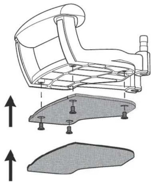
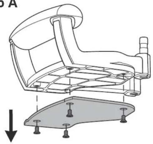
8 Plastic sliding plate LAS-STF-KA 65 with scratch protector EF-LAS-STF-KA 65/3x
Intended use
For using the edge bander on delicate or high-gloss surfaces.
With StickFix system for quick and easy replacement of the felt layer.
9 Polishing felt PF-STF 80 x 133 STF-H/5x
Intended use
For polishing high-gloss edging in combination with polish MPA 6000 and hand sanding block HSK 80 x 133.
10 Hand sanding block HSK 80x133 H
Intended use
Hand sanding block for mounting StickFix sanding discs, sanding cloths and polishing felt in the dimensions 80 x 133 mm.
11 Polish MPA 600
Intended use
MPA 600 polish for polishing high-gloss edges with the hand sanding block and polishing felt or a Festool polisher.
12 Hand abrasive Brilliant 2
Intended use
Suitable hand abrasive for hand sanding block Brilliant 2, grain size P 320, for smoothing cutting marks on the edge.
13 Accessories
Always use accessories and consumable materials approved by Festool. See Festool catalogue or www.festool.com.

Customer service and repair only through manufacturer or service workshops: Please find the nearest address at: www.festool.com/service

Use only original Festool spare parts! Order No. at: www.festool.com/service
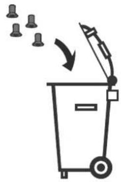
14 Environment
Do not dispose of the device together with domestic waste! Dispose of machines, accessories and packaging at an environmentally responsible recycling centre. Observe the valid national regulations.
Information on REACH: www.festool.com/reach
7 Lacksickel ZK-HW 45/45
Avsedd användning
11 B
11 C
13 A
natural_image
Technical diagram of a vehicle's internal components, showing a battery holder and lever assembly (no text or labels)13 B
14

15 A
natural_image
Technical line drawing of a mechanical chair assembly with mounting base and structural components (no text or symbols)15 B
natural_image
Simple line drawing of a trash bin with an arrow indicating waste disposal (no text or symbols)15 C