
PWSAM 20Li B2 - Electric grinder PARKSIDE - Free user manual and instructions
Find the device manual for free PWSAM 20Li B2 PARKSIDE in PDF.
| Product type | Cordless angle grinder |
| Brand | Parkside |
| Model | PWSAM 20Li B2 |
| Rated voltage | 20 V (Li-ion) |
| Disc diameter | 125 mm |
| No-load speed | 8500 rpm |
| Spindle thread | M14 |
| Weight (without battery) | 1.8 kg |
| Dimensions (L x W x H) | 320 x 100 x 90 mm |
| Power supply | Parkside 20 V battery (not included) |
| Disc fixing system | Clamping by nut with flange |
| Switch | Lockable with restart protection |
| Restart protection | Yes |
| Brake function | Electronic disc brake |
| Soft start | Yes |
| Variable speed | No |
| Spindle lock | Yes, for disc change |
| Additional handle | With fixing on left or right |
| Protective guard | Tool-adjustable orientation |
| Vibration level | ≤ 2.5 m/s² (grinding) |
| Sound level | 83 dB(A) |
| Maintenance | Clean ventilation slots with a brush; do not use aggressive products |
| Spare parts | Available from Parkside customer service (brush, disc support, guard, etc.) |
| Intended use | Grinding, cutting, brushing and deburring of metal and stone materials |
Frequently Asked Questions - PWSAM 20Li B2 PARKSIDE
User questions about PWSAM 20Li B2 PARKSIDE
0 question about this device. Answer the ones you know or ask your own.
Ask a new question about this device
Download the instructions for your Electric grinder in PDF format for free! Find your manual PWSAM 20Li B2 - PARKSIDE and take your electronic device back in hand. On this page are published all the documents necessary for the use of your device. PWSAM 20Li B2 by PARKSIDE.
USER MANUAL PWSAM 20Li B2 PARKSIDE

natural_image
Exterior view of a Panasonic electric shaver with a warning patch and cross symbol (no text or symbols on the device itself)
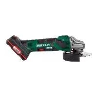
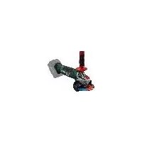
Akku-Winkelschleifer / Cordless Angle Grinder / Meuleuse d'angle sans fi l PWSAM 20-Li B2
DE AT CH
Cordless Angle Grinder
Translation of the original instructions
NL BE
Accu-haakse slijpmachine
Before reading, unfold the page containing the illustrations and familiarise yourself with all functions of the device.
FR BE
GB / MT Translation of the original instructions Page
natural_image
Three black triangular warning symbols on a white background, no text or labels present


NL BE


NL
BE
CE
cl. 空


ES


A
A
ES


ES
CE
0.3


natural_image
Three black triangular warning symbols on a white background, no text or labels present


IT MT


IT MT


IT
MT
CE
c.

CZ


CZ
!

A

A

A


CZ
A
A


CZ


CZ


CZ
CZ
CE


SK
A
A


SK


A
SK


SK


SK
CE
c. 精


HU


A
A
HU


CE
0.3


Brand : PARKSIDE
Model : PWSAM 20Li B2
Category : Electric grinder