DW077 - Laser pointer DEWALT - Free user manual and instructions
Find the device manual for free DW077 DEWALT in PDF.
Download the instructions for your Laser pointer in PDF format for free! Find your manual DW077 - DEWALT and take your electronic device back in hand. On this page are published all the documents necessary for the use of your device. DW077 by DEWALT.
USER MANUAL DW077 DEWALT
KLASSE 3R LASERPRODUKT
LASERPRODUKT DER KLASSE 3R
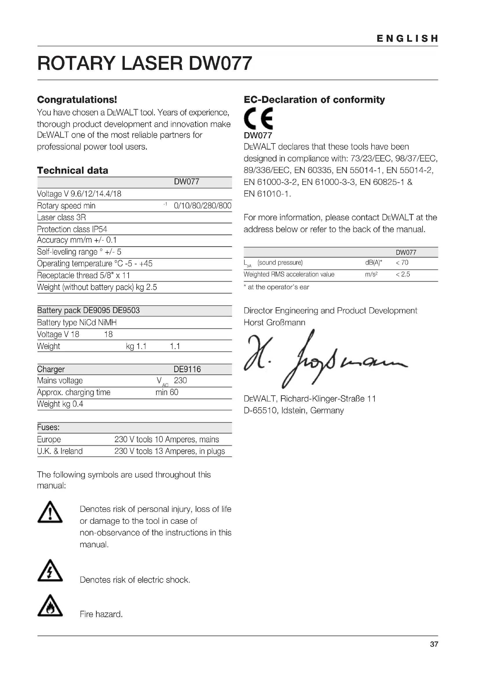
Congratulations! You have chosen a DEWALT tool. Years of experience, thorough product development and innovation make DEWALT one of the most reliable partners for professional power tool users. Technical data DW077 Voltage V 9.6/12/14.4/18 Rotary speed min
0/10/80/280/800 Laser class 3R Protection class IP54 Accuracy mm/m +/- 0.1 Self-leveling range ° +/- 5 Operating temperature °C -5 - +45 Receptacle thread 5/8" x 11 Weight (without battery pack) kg 2.5 Battery pack DE9095 DE9503 Battery type NiCd NiMH Voltage V 18 18 Weight kg 1.1 1.1 Charger DE9116 Mains voltage V
Approx. charging time min 60 Weight kg 0.4 Fuses: Europe 230 V tools 10 Amperes, mains U.K. & Ireland 230 V tools 13 Amperes, in plugs The following symbols are used throughout this manual: Denotes risk of personal injury, loss of life or damage to the tool in case of non-observance of the instructions in this manual. Denotes risk of electric shock. Fire hazard. EC-Declaration of conformity DW077 DEWALT declares that these tools have been designed in compliance with: 73/23/EEC, 98/37/EEC, 89/336/EEC, EN 60335, EN 55014-1, EN 55014-2, EN 61000-3-2, EN 61000-3-3, EN 60825-1 & EN 61010-1. For more information, please contact DEWALT at the address below or refer to the back of the manual. DW077
- at the operator’s ear Director Engineering and Product Development Horst Großmann DEWALT, Richard-Klinger-Straße 11 D-65510, Idstein, Germany38 ENGLISH Safety instructions When using power tools, always observe the safety regulations applicable in your country to reduce the risk of fire, electric shock and personal injury. Read all of this manual carefully before operating the tool. Also refer to the manual of any power tool that will be used with this tool. Save this manual for future reference. General 1 Keep work area clean Cluttered areas and benches can cause accidents. 2 Consider work area environment Do not expose power tools to humidity. Keep work area well lit. Do not use power tools in the presence of flammable liquids or gases. 3 Guard against electric shock Prevent body contact with earthed surfaces (e.g. pipes, radiators, cookers and refrigerators). For use under extreme conditions (e.g. high humidity, when metal swarf is being produced, etc.) electric safety can be improved by inserting an isolating transformer or a (FI) earth-leakage circuit-breaker. 4 Keep children away Do not let children come into contact with the tool or extension cord. Supervision is required for those under 16 years of age. 5 Use appropriate tool The intended use is described in this instruction manual. Do not force small tools or attachments to do the job of a heavy-duty tool. The tool will do the job better and safer at the rate for which it was intended. Warning! The use of any accessory or attachment or performance of any operation with this tool, other than those recommended in this instruction manual may present a risk of personal injury. 6 Maintain tools with care Keep the tools in good condition and clean for better and safer performance. Follow the instructions for maintenance and changing accessories. Inspect the tool cords at regular intervals and, if damaged, have them repaired by an authorized DEWALT repair agent. Keep all controls dry, clean and free from oil and grease. 7 Store idle tools When not in use, power tools must be stored in a dry place and locked up securely, out of reach of children. 8 Check for damaged parts Before using the tool, carefully check it for damage to ensure that it will operate properly and perform its intended function. Check for misalignment and seizure of moving parts, breakage of parts and any other conditions that may affect its operation. Have damaged guards or other defective parts repaired or replaced as instructed. Do not use the tool if the switch is defective. Have the switch replaced by an authorized DEWALT repair agent. 9 Remove the battery pack Remove the battery pack when not in use, before servicing and when changing accessories. 10 Have your tool repaired by an authorized DEWALT repair agent This power tool is in accordance with the relevant safety regulations. To avoid danger, electric appliances must only be repaired by qualified technicians. Additional safety instructions for lasers
- This laser complies with class 3R according to DIN EN 60825-1:2001-11 (max 5 mW, 600-680 nm). Do not replace a laser diode with a different type. If damaged, have the laser repaired by an authorised repair agent. Only qualified and trained persons are allowed to install, adjust and operate the laser equipment. Areas in wich class 3R lasers are used have to be posted with an appropriate laser warning sign.
- Do not use the laser for any purpose other than projecting laser lines.
- Before first use, check that the safety warnings on the label have been formulated in your language. Do not use the tool if it does not carry the warnings in your language!
- Do not remove any of the warning labels from the tool.
- Do not let children come in contact with the laser. As the beam of a class 3R laser provides high visibility over longer distances, the potential risk of damage to the eye remains unchanged within the radius of application.39 ENGLISH
- Never look into the laser beam directly and intentionally.
- Never shine other persons in the eyes with the laser beam.
- Do not use optical tools to view the laser beam unless specifically approved by a laser officer.
- Always set up the tool at a position where the laser beam cannot cross any person at eye level. Be extra alert for the presence of stairs and specular surfaces. Additional safety instructions for battery packs Fire hazard! Avoid metal short circuiting the contacts of a detached battery pack. Do not store or carry the battery pack without the battery cap placed over the contacts.
- The battery fluid, a 25-30% solution of potassium hydroxide, can be harmful. In case of skin contact, flush immediately with water. Neutralize with a mild acid such as lemon juice or vinegar. In case of eye contact, rinse abundantly with clean water for at least 10 minutes. Consult a physician.
- Never attempt to open a battery pack for any reason. Labels on charger and battery pack In addition to the pictographs used in this manual, the labels on the charger and the battery pack show the following pictographs: 100% Battery charging 100% Battery charged Battery defective Do not probe with conductive objects Do not charge damaged battery packs Read instruction manual before use Use only with DEWALT battery packs, others may burst, causing personal injury and damage Do not expose to water Have defective cords replaced immediately +40 ˚c +4 ˚c Charge only between 4 °C and 40 °C Discard the battery pack with due care for the environment Do not incinerate the battery pack Labels on tool The following pictographs are shown on the tool: Read the instruction manual before use Laser warning Class 3R laser Do not look into the laser beam. Protection class: IP54 Package contents The package contains: 1 Rotary laser 1 Wall mount 1 Remote control 1 Target card40 ENGLISH 1 Pair of glasses 1 Kitbox 1 Charger (DW077K/DW077KH) 1 Battery pack (DW077K/DW077KH) 1 Instruction manual
- Take the time to thoroughly read and understand this manual prior to operation. Description (fig. A) The rotary laser DW077 has been designed to project laser lines to aid in professional applications. The tool can be used both inside and outside for horizontal (level) and vertical (plumb) alignment. The tool can also produce a stationary laser dot that can be directed manually to establish or transfer a mark. The applications range from drop-ceiling installation and wall layout to foundation leveling and deck building. The tool accepts DEWALT battery packs of 9.6, 12,
1 On/off switch 2 Carrying handle 3 Leveling knob 4 Wall mount 5 Rack pinion locking knob 6 Wall mount clamp 7 Wall mount clamp lock 8 Fitting knob 9 Rack pinion wheel 10 Rotary laser head 11 Battery pack Charger Your DE9116 charger accepts DEWALT NiCd and NiMH battery packs ranging from 7.2 V to 18 V. 11 Battery pack 12 Release buttons 13 Charger 14 Charging indicator (red) Display 15 Power indicator 16 Leveling indicator (X-axis) 17 Leveling indicator (Y-axis) 18 Scan mode activation key 19 Rotation speed setting key 20 Adjustment keys left/right Remote control 18 Scan mode activation key 19 Rotation speed setting key 20 Adjustment keys left/right 21 Adjustment keys up/down 22 Manual adjustment key Electrical safety The electric motor has been designed for various voltages (see technical data). Always check that the battery pack power corresponds to the voltage on the rating plate. Also make sure that the voltage of your charger corresponds to that of your mains. Your DEWALT charger is double insulated in accordance with EN 60335. Mains plug replacement (U.K. & Ireland only)
- Should your mains plug need replacing and you are competent to do this, proceed as instructed below. If you are in doubt, contact an authorized DEWALT repair agent or a qualified electrician.
- Disconnect the plug from the supply.
- Cut off the plug and dispose of it safely; a plug with bared copper conductors is dangerous if engaged in a live socket outlet.
- Only fit 13 Amperes BS1363A approved plugs fitted with the correctly rated fuse (1).
- The cable wire colours, or a letter, will be marked at the connection points of most good quality plugs. Attach the wires to their respective points in the plug (see below). Brown is for Live (L) (2) and Blue is for Neutral (N) (11).
- Before replacing the top cover of the mains plug ensure that the cable restraint (3) is holding the outer sheath of the cable firmly and that the two leads are correctly fixed at the terminal screws.41 ENGLISH Never use a light socket. Never connect the live (L) or neutral (N) wires to the earth pin marked E or . Using an extension cable An extension cord should not be used unless absolutely necessary. Use an approved extension cable suitable for the power input of your charger (see technical data). The minimum conductor size is 1 mm
the maximum length is 30 m. Unpacking Fitting the warning label (fig. B) The safety warnings on the label shown on the tool must be formulated in the language of the user. For that purpose, a separate sheet of self-adhesive labels has been supplied with the tool.
- Check that the safety warnings on the label have been formulated in your language. The warnings should read as follows: LASER RADIATION
DO NOT STARE INTO BEAM
CLASS 3R LASER PRODUCT
- If the warnings are in a foreign language, proceed as follows: – Draw the required label from the sheet. – Carefully place the label over the foreign language. – Press the label in place. Assembly and adjustment
- Prior to assembly and adjustment, always remove the battery pack.
- Always switch off the tool before inserting or removing the battery pack. Use only DEWALT battery packs and chargers. Battery pack (fig. A & C1 - C4) Charging the battery pack (fig. A) When charging the battery pack for the first time, or after prolonged storage, it will only accept an 80% charge. After several charge and discharge cycles, the battery pack will attain full capacity. Always check the mains prior to charging the battery pack. If the mains is functioning but the battery pack does not charge, take your charger to an authorised DEWALT repair agent. Whilst charging, the charger and the battery pack may become warm to touch. This is a normal condition and does not indicate a problem. Do not charge the battery pack at ambient temperatures < 4 °C or > 40 °C. Recommended charging temperature: approx. 24 °C.
- To charge the battery pack (11), insert it into the charger (13) as shown and plug in the charger. Be sure that the battery pack is fully seated in the charger. The red charging indicator (14) will blink. After approx. 1 hour, it will stop blinking and remain on. The battery pack is now fully charged and the charger automatically switches to equalise mode. After approx. 4 hours, it will switch to maintenance charge mode. The battery pack can be removed at any time or left in the connected charger indefinitely.
- The red charging indicator flashes rapidly to indicate a charging problem. Reinsert the battery pack or try a new one. If the new pack also refuses to charge, have your charger tested by an authorized DEWALT repair agent.
- When plugged into power sources such as generators or sources that convert DC to AC, the red charging indicator may blink twice, switch off and repeat. This indicates a temporary problem of the power source. The charger will automatically switch back to normal operation. Inserting and removing the battery pack (fig. C1)
- Insert the battery pack (11) into the tool until it clicks in place.
- To remove the battery pack, press the two release buttons (12) simultaneously and pull the pack out of the tool.42 ENGLISH Battery cap (fig. C2) A protective cap is supplied to cover the contacts of a detached battery pack. Without the protective cap in place, loose metal objects could short circuit the contacts, causing a fire hazard and damaging the battery pack.
- Take off the protective cap (11) before placing the battery pack (24) in the charger or tool.
- Place the protective cap over the contacts immediately after removing the battery pack from the charger or tool. Make sure the protective cap is in place before storing or carrying a detached battery pack. Equalization mode The equalization mode helps to maintain the optimum capacity of the battery pack. It is therefore recommended to use the equalization mode weekly or every 10 charge/ discharge cycles.
- Charge the battery pack as described above.
- When the charging indicator stops blinking, leave the battery in the charger for approx. 4 hours. Hot Pack Delay When the charger detects a battery that is hot, it automatically starts a Hot Pack Delay, suspending charging until the battery has cooled. After the battery has cooled, the charger automatically switches to the pack charging mode. This feature ensures maximum battery life. The red indicator (14) blinks long, then short while in the Hot Pack Delay mode. Low battery indicator (fig C1) The tool has been equipped with a low battery indicator (15) located on the control panel. The low battery indicator is lit while the tool is switched on. It will blink to indicate that the battery pack needs to be recharged and the tool will automatically shut down.
- Switch off the tool and take out the battery pack (11) to charge it as soon as the indicator blinks. The tool remains non-operational as long as a low battery pack is attached to it. Battery type (fig. C3 & C4) The tool is suitable for battery packs with different voltages.
- To fit battery packs of 18 volt, rotate the adapter plate (25) into position A.
- To fit battery packs of 9.6, 12 or 14.4 volt, rotate the adapter plate (25) into position B. Refer to the table in the back for a selection of applicable battery packs. Setting up the tool (fig. D1 - D5) The tool facilitates various set-ups, making it useful for several applications. Floor set-up (fig. D1)
- Place the tool on a relatively smooth and level surface.
- Adjust the tool for a level or plumb application. Wall set-up (fig. D2 - D4) The tool has been equipped with a wall mount (11) for mounting to a wall track to aid in drop ceiling installation and other specialty leveling projects (fig. D2).
- Fit the tool to the wall mount by inserting the threaded pin (23) into one of the receptacles in the tool and tightening the knob (15).
- Turn the tool on its side with the wall mount clamp (13) in position for attachment to the wall track (fig. D3).
- With the wall mount (11) facing the wall, turn the wall mount clamping lock (14) in the clockwise direction to open the clamp jaws.
- Place the clamp jaws around the wall track and turn the wall mount clamping lock (14) in the anti-clockwise direction to close the clamp jaws shut on the track.
- Ensure that the wall mount clamping lock (14) is securely locked. Before attaching the tool to a wall track ensure that the track is properly secured to the wall.
- Alternatively, the tool can be hung on the wall using the mounting holes (27) in the wall mount (fig. D2).43 ENGLISH – Hold the tool at the desired position against the wall and mark the location of the two mounting holes on the wall (fig. D4). – Drill a hole at each of the marked locations (required: ø 6 mm, approx. 35 mm deep). – Insert a corresponding plug into each of the holes. – Turn a screw into each of the plugs (required: 6 x 50 mm). – Hang the tool on the screws.
- Adjust the leveling knob (3) to stabilise the tool when necessary.
- Adjust the tool for a level application. Tripod set-up (fig. D5) The tool has been equipped with a tripod receptacle for mounting to the DE0735/DE0736 tripod (optional) or any other tripod with the required ratings stated in the technical data.
- Place the tripod (28) on a relatively smooth and level surface.
- Mount the tool to the tripod by turning the threaded pin (29) into the receptacle (30) in the base.
- Adjust the tool for a level or plumb application. Adjusting the tool (fig. A, E1 & E2) The tool can be adjusted for both level (fig. E1) and plumb (fig. E2) applications. Self-leveling feature (fig. A)
- To initiate the leveling procedure, switch on the tool. The leveling procedure is indicated by the flashing of the leveling indicators (16 & 17) and the laser beam. Once the tool has found its level position the leveling indicators and the laser beam will stop flashing and remain on.
- The leveling indicators and the laser beam repeatedly flash three times rapidly to indicate that the tool has been set up at a slope that is beyond the self-leveling range of 5°. Switch the tool off, re-adjust the tool set-up within the self- leveling range and switch the tool on again. Level adjustment (fig. E1)
- Place the tool into the required position as shown.
- Switch on the tool to initiate the leveling procedure. Plumb adjustment (fig. E2)
- Place the tool into the required position as shown.
- Switch on the tool to initiate the leveling procedure. As the leveling procedure for plumb applications only requires adjustment of the Y axis, only the corresponding leveling indicator (17) will be operational. Manually adjusting the level position (fig. A) By using the remote control the tool can be adjusted manually. The manual adjustment mode is particularly useful in applications with slope angles in both X and Y-axis.
- To activate the manual adjustment mode press the key (22). The leveling indicators (16 & 17) go off.
- Use the keys (20) to adjust the tool in the X-axis.
- Use the keys (21) to adjust the tool in the Y-axis.
- To discontinue the manual adjustment mode, press the key (22) again. After discontinuing the manual leveling mode the self-leveling feature automatically takes over and re-adjusts the tool to level position. The manual adjustments will be lost immediately! Aligning the laser line (fig. A & F1 - F5) Level alignment
- With the tool switched on and the laser head rotating, align the laser line with the position mark.
- If adjustment is required, proceed as follows: With tool in floor set-up (fig. F1):
- The tool can be placed on any sturdy object to obtain the required height. With tool in wall set-up (fig. F2):
- Loosen the locking knob (12) and adjust the rack pinion wheel (9) to set the tool to the correct position. Tighten the locking knob (12). With tool in tripod set-up (fig. F3):
- Adjust the tripod to set the tool to the required height. Plumb alignment (fig. A, F4 & F5)
- With the tool switched on and the laser head rotating, align the laser line with the position mark.
- If adjustment is required, proceed as follows:44 ENGLISH
- Use the keys (20) to move the laser head until the laser line aligns with the position mark (fig. A). Slope alignment (fig. A) If the application requires the laser line to align at a slope angle, proceed as follows:
- With the tool switched on and the laser head rotating, activate the manual leveling mode.
- Align the laser line with the slope: – Use the keys (20) to adjust the tool in the X-axis. – Use the keys (21) to adjust the tool in the Y-axis. Instructions for use
- Always observe the safety instructions and applicable regulations.
- Always mark the center of the laser line or dot.
- To increase working distance and accuracy, set up the tool in the middle of your working area.
- Extreme temperature changes cause movement of internal parts that may affect the accuracy of the tool. Regularly check the accuracy while using the tool under these circumstances.
- Although the tool corrects small out-of-level errors automatically, when it has registered a bump, re-adjustment to balance or set-up may be required.
- If the tool has been dropped or has tipped over, have the laser head calibrated by a qualified repair agent.
- For your own comfort, always use the remote control to operate the tool. The remote control not only allows you to operate the tool from a distance, it also keeps you from touching the tool, thereby reducing the risk of affecting the tool’s balance and set-up. Prior to operation:
- Carry out the field calibration checks to confirm its accuracy.
- Make sure the tool has been set up securely. Switching on and off (fig. A)
- To switch the tool on, press the on/off switch (1).
- To switch the tool off, press the on/off switch (1) again. Setting the rotation speed (fig. G) The laser head can be set to different rotation speed settings, thus determining the quality of the line.
- Press the key (19). The rotation speed will cycle from “fast” to “medium”, “slow”, “crawling” and “stationary” each time the key is pressed.
- For a bright line, set the laser head to a slow rotation speed.
- For a solid line, set the laser head to a fast rotation speed. Rotating the laser head (fig. H1 & H2) In the stationary position, the laser head can be moved both to the left and to the right. Level applications:
- Use the keys (20) to move the laser head into the required direction. Plumb applications:
- Use the keys (21) to move the laser head into the required direction. Manually rotating the laser head (fig. H2) The laser head can also be rotated manually.
- Turn the laser head (10) into the required position. Do not attempt to move the laser head while it is rotating at a preset rotation speed. Scan mode (fig. I) The laser head can be set to different speed settings while moving back and forth, thus projecting a scanning laser line.
- Press the key (18) to activate the scan mode. The scan speed starts at “fast” rate.
- To set the scan speed press the key (19). The scan speed will cycle from “crawling” to “slow”, “medium” and “fast” each time the key is pressed.
- Level applications: – Use the keys (20) to move the scan area into the required direction. – Use the keys (21) to adjust the scan area.
- Plumb applications: – Use the keys (21) to move the scan area into the required direction.
- Press the key (18) to discontinue the scan mode.45 ENGLISH Vertical transfer feature (fig. J1 & J2) The alignment ribs (31) help locating the position of the up laser beam (32) over a position mark on the floor.
- Mark a crossline on the floor.
- Place the tool over the centre of the crossline, aligning the ribs with the floor markings.
- Transfer the centre of the crossline using the up laser beam. Remember: This feature works only on flat surfaces and can only be used as a rough position transferring aid. For a more accurate transfer of position marks, we recommend to use a dedicated DEWALT laser pointer. Out-of-level alert The out-of-level alert activates automatically 8 seconds after the leveling procedure has been completed. Once the out-of-level alert is activated, the tool monitors its level position continuously. Depending on the registered level of deviation the tool will respond to level errors as follows: – Deviations < 2 mm over 10 m: a level error is automatically corrected without notifying. – Deviations 2 - 20 mm over 10 m: a level error is automatically corrected. The laser head temporarily stops rotating and the laser beam starts flashing to indicate that the tool re-adjusts to level position. – Deviations > 20 mm over 10 m: a level error leads to interruption of the tool’s operation. The laser head stops rotating and the laser beam goes off. A rapidly beeping audio signal is produced and the on/off indicator flashes simultaneously. To resume the operation:
- Switch the tool off. Check the balance and set- up and re-adjust if required before switching the tool on again. Tool aids (fig. K1 - K4) Several aids have been supplied that might be helpful while operating the tool. Remote control (fig. K1) The remote control allows a manual intervention of the self-leveling feature when slope adjustment is required. The maximum slope angle corresponds to the self-leveling range of the tool. The remote control also allows you to activate the laser line and control the laser head from distances up to 30 m radius. Laser enhancement glasses (fig. K2) The red lens glasses improve the visibility of the laser beam under bright light conditions or over long distances. Providing best results indoors, the lens filters out ambient light and intensifies the projected dot or line. The glasses do not keep the laser beam from entering the eyes. Never look into the laser beam directly with these glasses. DE0730 Target card (fig. K3) The target card locates and marks the laser beam as the beam crosses the card, thus enhancing the visibility of the projected line. The laser beam passes through the red plastic surface and is reflected by the reflective rear side of the card. Supporting easy use during plumb and level adjustment, the card is marked with inch and metric scales, and has magnets at the top to hold it to ceiling track or steel studs. Wall mount (fig. K4) The wall mount may also be used as a base to provide extra stability for the tool. Optional accessories Consult your dealer for further information on the appropriate accessories. These are: – DE0772 Digital laser detector – DE0734 Grade rod – DE0735 Tripod – DE0736 Tripod Battery packs Voltage NiCd NiMH
18 DE9095/DE9096 DE903946 Maintenance Your DEWALT power tool has been designed to operate over a long period of time with a minimum of maintenance. Continuous satisfactory operation depends upon proper tool care and regular cleaning. Field calibration check (fig. F5, L1 & L2) The field calibration checks must be performed securely and accurately to make a correct diagnosis. Whenever an error is registered, have the tool calibrated by a qualified repair agent. Always have the laser head calibrated by a qualified repair agent. Level checks (fig. L1 & L2) The following checks are performed to check the calibration of laser head for level alignment.
- Place the tool in an area at about 15 m from a vertical surface.
- With the tool in a tripod set-up, adjust the tool for a level application. To perform a level check of the X-axis (fig. L1):
- Position the tool so that the X-axis is parallel with the vertical surface.
- Switch on the tool and rotate the head until the laser dot appears on the vertical surface.
- Mark the centre of the laser beam.
- Switch off the tool and rotate it 180° so that the X-axis is parallel with the vertical surface the other way around.
- Switch on the tool, rotate the head and once again mark the centre of the laser dot on the surface. Switch off the tool.
- Measure the difference between the markings.
- If the difference between the markings is 3.2 mm or less, the laser head is properly calibrated.
- If the difference between the markings is more than 3.2 mm, the laser head must be calibrated. To perform a level check of the Y-axis (fig. L2):
- Position the tool so that the Y-axis is parallel with the vertical surface.
- Following the same procedure as described above, mark the centre of the laser dot on the surface with the tool in this position, after which the tool is rotated 180° to mark the centre of the laser dot once again.
- Measure the difference between the markings.
- If the difference between the markings is 3.2 mm or less, the laser head is properly calibrated.
- If the difference between the markings is more than 3.2 mm, the laser head must be calibrated. Plumb check (fig. F5) The following check is performed to check the calibration of laser head for plumb alignment.
- Place the tool in an area at about 1 m from a vertical surface.
- With the tool in a floor set-up, adjust the tool for a plumb application.
- Mark the top and bottom of the vertical surface using a plumb bob.
- Switch on the tool and align the laser beam with the lower marking.
- Using the remote control, move the head until the laser beam is at the upper marking.
- If the laser beam aligns with the top marking, the laser head is properly calibrated.
- If the laser beam does not align with the top marking, the laser head must be calibrated. Cleaning
- Unplug the charger before cleaning the housing with a soft cloth.
- Remove the battery pack before cleaning your power tool.
- Keep the ventilation slots clear and regularly clean the housing with a soft cloth.
- When necessary, clean the lens using a soft cloth or a cotton bud soaked in alcohol. Do not use any other cleaning agents. Protecting the environment Separate collection. This product must not be disposed of with normal household waste. Should you find one day that your DEWALT product needs replacement, or if it is of no further use to you, do not dispose of it with household waste. Make this product available for separate collection. ENGLISH47 Separate collection of used products and packaging allows materials to be recycled and used again. Re-use of recycled materials helps prevent environmental pollution and reduces the demand for raw materials. Local regulations may provide for separate collection of electrical products from the household, at municipal waste sites or by the retailer when you purchase a new product. DEWALT provides a facility for the collection and recycling of DEWALT products once they have reached the end of their working life. To take advantage of this service please return your product to any authorised repair agent who will collect them on our behalf. You can check the location of your nearest authorised repair agent by contacting your local DEWALT office at the address indicated in this manual. Alternatively, a list of authorised DEWALT repair agents and full details of our after-sales service and contacts are available on the Internet at: www.2helpU.com Rechargeable battery pack This long life battery pack must be recharged when it fails to produce sufficient power on jobs which were easily done before. At the end of its technical life, discard it with due care for our environment:
- Run the battery pack down completely, then remove it from the tool.
- NiCd and NiMH cells are recyclable. Take them to your dealer or a local recycling station. The collected battery packs will be recycled or disposed of properly. GUARANTEE
- 30 DAY NO RISK SATISFACTION GUARANTEE • If you are not completely satisfied with the performance of your DEWALT tool, simply return it within 30 days, complete as purchased, to the point of purchase, for a full refund or exchange. Proof of purchase must be produced.
- ONE YEAR FREE SERVICE CONTRACT • If you need maintenance or service for your DEWALT tool, in the 12 months following purchase, it will be undertaken free of charge at an authorized DEWALT repair agent. Proof of purchase must be produced. Includes labour and spare parts for Power Tools. Excludes accessories.
- ONE YEAR FULL WARRANTY • If your DEWALT product becomes defective due to faulty materials or workmanship within 12 months from the date of purchase, we guarantee to replace all defective parts free of charge or, at our discretion, replace the unit free of charge provided that:
- The product has not been misused.
- Repairs have not been attempted by unauthorized persons.
- Proof of purchase date is produced. This guarantee is offered as an extra benefit and is additional to consumers statutory rights. For the location of your nearest authorized DEWALT repair agent, please use the appropriate telephone number on the back of this manual. Alternatively, a list of authorized DEWALT repair agents and full details on our after-sales service are available on the Internet at www.2helpU.com ENGLISH48 ESPAÑOL