DCE825NG18 - Laser pointer DEWALT - Free user manual and instructions
Find the device manual for free DCE825NG18 DEWALT in PDF.
| Brand | DeWalt |
| Model | DCE825NG18 |
| Product type | Laser level |
| Laser class | II |
| Laser wavelength | 510–530 nm (visible) |
| Laser power | ≤1.0 mW |
| Range | 85 m (280'); 100 m (330') with detector |
| Accuracy | ±3.0 mm for 10 m |
| Power supply | DEWALT Li-Ion battery pack 12V or 18V |
| Self-leveling range | ±4° |
| Beam types | Horizontal and vertical lines, cross, and up to 5 points (depending on model) |
| Operating temperature | 4 °C to 40 °C |
| Storage temperature | -20 °C to 60 °C |
| Max relative humidity | 80 % at 31 °C, decreasing to 50 % at 40 °C |
| Protection rating | IP54 |
| Max altitude | 2000 m (6500') |
| Mount | Magnetic pivot mount with 1/4"-20 and 5/8"-11 threads |
| Battery gauge | 4 LED indicators (flashing for low battery or incomplete shutdown) |
| Cleaning | Soft dry cloth; do not use solvents |
| Repairs | Only by authorized centers; any disassembly voids warranty |
| Safety | Do not look directly into the beam; class 2 laser product |
Frequently Asked Questions - DCE825NG18 DEWALT
User questions about DCE825NG18 DEWALT
0 question about this device. Answer the ones you know or ask your own.
Ask a new question about this device
Download the instructions for your Laser pointer in PDF format for free! Find your manual DCE825NG18 - DEWALT and take your electronic device back in hand. On this page are published all the documents necessary for the use of your device. DCE825NG18 by DEWALT.
USER MANUAL DCE825NG18 DEWALT
DCE822G18 12V/18V 2-Dot Cross Line Laser DCE825G18 12V/18V 5-Dot Cross Line Laser

natural_image
Line drawing of two DEWALT devices with battery and control buttons (no text or symbols on the devices themselves)A
text_image
Diagram of a portable electronic device with labeled components and a light bulb icon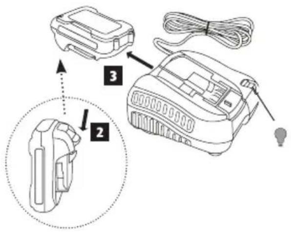
text_image
Diagram showing three labeled components of a device with arrows indicating assembly steps, including a magnified view of the internal structure.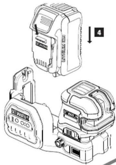
text_image
Technical diagram showing two device configurations with labeled parts and a numbered arrow indicating step 4.B
text_image
1 2 DEMAIGT DEMAIGT
text_image
DEWALT ① ⑩ ③ ② ⑨ DCE825G18 DCE822G18④
7
8
text_image
3 x15
x2
6

text_image
STEP 2 a b STEP 4 STEP 3 ≥ 10 m STEP 2 45° 90° STEP 3 STEP 1E
text_image
>30' (100m) a b ①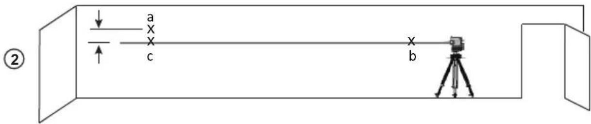
text_image
a x x c b ②F
text_image
STEP 7 a b STEP 4 a STEP 6 b STEPS 2, 3 5' (1.5 m) STEP 1 STEP 5
①
text_image
b a②
text_image
b c aH
text_image
① ≥ 20' (6m) a x x b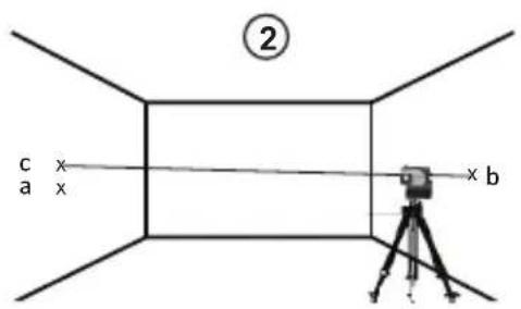
text_image
② c x a x x bI
①
text_image
a D1 b c②
text_image
a b c d e③
text_image
f a b e d c4
text_image
a f g b e d cJ
text_image
Technical diagram of a device with labeled components and directional arrows indicating orientation or movement.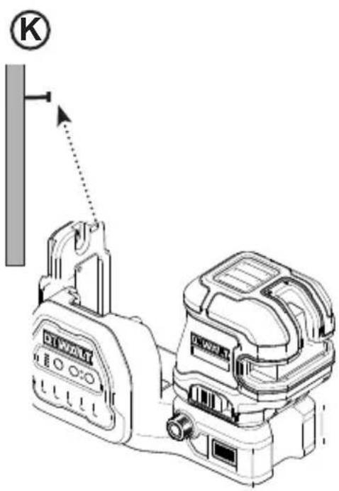
text_image
KL
text_image
Technical diagram of a device rear panel with labeled components and a U-shaped symbol indicating a specific section.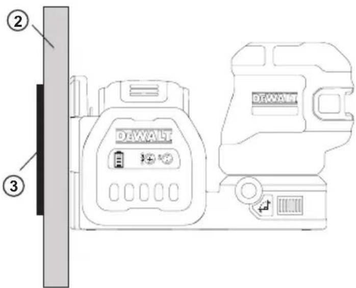
text_image
② DEWALT ③M
text_image
1/4-20 5/8-11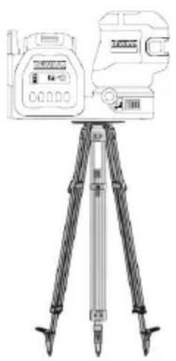
natural_image
Line drawing of a surveying instrument mounted on a tripod, no text or symbols presentN
text_image
Technical diagram of a mechanical device with numbered components for identification©
text_image
NICHES CV 1 2 3 4 5 6 7 DEWALTP
natural_image
Simple line drawing of a pair of eyeglasses (no text or symbols)Contents
- Laser Information
- User Safety
- Battery Safety
- Powering the Laser
- Operating Tips
- Turning the Laser ON
- Checking Laser Accuracy
• Field Calibration Check - Using the Laser
- Maintenance
- Troubleshooting
- Accessories
• Service and Repairs - Warranty
- Specifications
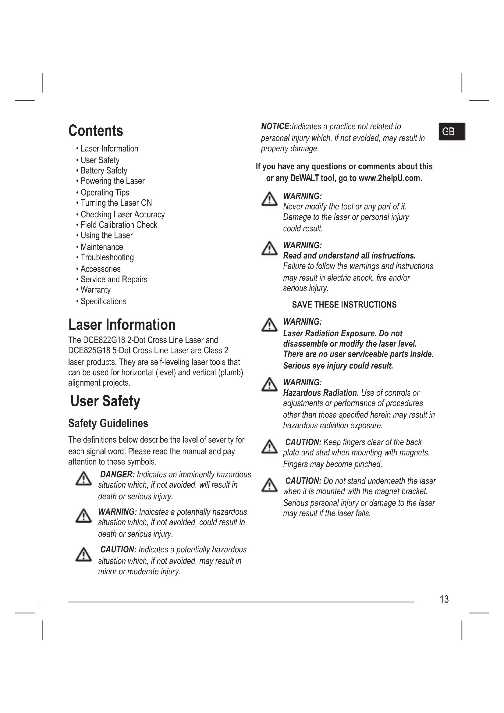
Laser Information
The DCE822G18 2-Dot Cross Line Laser and DCE825G18 5-Dot Cross Line Laser are Class 2 laser products. They are self-leveling laser tools that can be used for horizontal (level) and vertical (plumb) alignment projects.
User Safety
Safety Guidelines
The definitions below describe the level of severity for each signal word. Please read the manual and pay attention to these symbols.

DANGER: Indicates an imminently hazardous situation which, if not avoided, will result in death or serious injury.

WARNING: Indicates a potentially hazardous situation which, if not avoided, could result in death or serious injury.

CAUTION: Indicates a potentially hazardous situation which, if not avoided, may result in minor or moderate injury.
NOTICE: Indicates a practice not related to personal injury which, if not avoided, may result in property damage.
GB
If you have any questions or comments about this or any DEWALT tool, go to www.2helpU.com.

WARNING:
Never modify the tool or any part of it. Damage to the laser or personal injury could result.

WARNING:
Read and understand all instructions.
Failure to follow the warnings and instructions may result in electric shock, fire and/or serious injury.
SAVE THESE INSTRUCTIONS

WARNING:
Laser Radiation Exposure. Do not disassemble or modify the laser level. There are no user serviceable parts inside. Serious eye injury could result.

WARNING:
Hazardous Radiation. Use of controls or adjustments or performance of procedures other than those specified herein may result in hazardous radiation exposure.

CAUTION: Keep fingers clear of the back plate and stud when mounting with magnets. Fingers may become pinched.

CAUTION: Do not stand underneath the laser when it is mounted with the magnet bracket. Serious personal injury or damage to the laser may result if the laser falls.
GB
The label on your laser may include the following symbols.
| Symbol Meaning | |
| VVolts | |
| mW Milliwatts | |
| Laser Warning | |
| nm Wavelength in nanometers | |
| 2Class 2 Laser | |
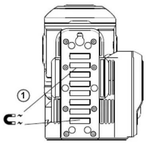
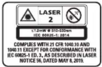
Warning Labels
For your convenience and safety, the following labels are on your laser (Figure C 10).


WARNING: To reduce the risk of injury, user must read instruction manual.
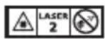
WARNING: LASER RADIATION. DO NOT STARE INTO BEAM. Class 2 Laser Product.


WARNING: Keep clear of magnet. Magnet hazard can disturb pacemaker operation and result in serious injury or death.
text_image
LASER 2 ≤1.0mW @ 510-530nm IEC 60025-1: 2014 COMPLIES WITH 21 CFR 1040.10 AND 1040.11 EXCEPT FOR CONFORMANCE WITH IEC 60025-1 ED. 3, AS DESCRIBED IN LASER NOTICE 56, DATED MAY 8, 2019.- If the equipment is used in a manner not specified by the manufacturer, the protection provided by the equipment may be impaired.
- Do not operate the laser in explosive atmospheres, such as in the presence of flammable liquids, gases, or dust. This tool may create sparks which may ignite the dust or fumes.
-
Store an idle laser out of reach of children and other untrained persons. Lasers are dangerous in the hands of untrained users.
-
Tool service MUST be performed by qualified repair personnel. Service or maintenance performed by unqualified personnel may result in injury. To locate your nearestDEWALTservice center go to www.2helpU.com.
- Do not use optical tools such as a telescope or transit to view the laser beam. Serious eye injury could result.
- Do not place the laser in a position which may cause anyone to intentionally or unintentionally stare into the laser beam. Serious eye injury could result.
- Do not position the laser near a reflective surface which may reflect the laser beam toward anyone's eyes. Serious eye injury could result.
- Turn the laser off when it is not in use. Leaving the laser on increases the risk of staring into the laser beam.
- Do not modify the laser in any way. Modifying the tool may result in hazardous laser radiation exposure.
- Do not operate the laser around children or allow children to operate the laser. Serious eye injury may result.
- Do not remove or deface warning labels. If labels are removed, the user or others may inadvertently expose themselves to radiation.
- Position the laser securely on a level surface. If the laser falls, damage to the laser or serious injury could result.
Personal Safety
- Stay alert, watch what you are doing, and use common sense when operating the laser. Do not use the laser when you are tired or under the influence of drugs, alcohol, or medication. A moment of inattention while operating the laser may result in serious personal injury.
- Do not overreach. Keep proper footing and balance at all times. Proper footing and balance enables better control of the tool in unexpected situations.
- Use personal protective equipment. Always wear eye protection. Depending on the work conditions, wearing protective equipment such as a dust mask, non-skid safety shoes, hard hat, and hearing protection will reduce personal injury.
Tool Use and Care
- Do not use the laser if the Power/Transport Lock switch does not turn the laser on or off. Any tool that cannot be controlled with the switch is dangerous and must be repaired.
- Follow instructions in the Maintenance section of this manual. Use of unauthorized parts or failure to follow Maintenance instructions may create a risk of electric shock or injury.
Battery Safety

WARNING:
Batteries can explode, or leak, and can cause injury or fire. To reduce this risk:
- Carefully follow all instructions and warnings on the battery label and package, and the accompanying Battery Safety manual.
- Do not dispose of batteries in fire.
- Keep batteries out of reach of children.
- Remove batteries when the device is not in use.
- Use only the charger specified for your rechargeable battery pack.
- Disconnect the battery pack from the laser before making any adjustments, changing accessories, or storing the laser. Such preventative safety measures reduce the risk of starting the laser accidentally.
- Use the laser only with specifically designated battery packs. Use of other battery packs may create a risk of injury and fire.
- Under abusive conditions, liquid may be ejected from the battery; avoid contact. If contact accidentally occurs, flush with water. If liquid contacts eyes, additionally seek medical help. Liquid ejected from the battery may cause irritation or burns.
- Do not use a battery pack or laser that is damaged or modified. Damaged or modified batteries may exhibit unpredictable behavior resulting in fire, explosion, or risk of injury.
- Do not expose a battery pack or laser to fire or excessive temperature. Exposure to fire or temperature above 265 °F (130 °C) may cause an explosion.
- Follow all the charging instructions and do not charge the battery pack outside of the temperature range specified in the instructions. Charging improperly or at temperatures outside of the specified range may damage the battery and increase the risk of fire.
- Do not store or use the tool and battery pack in locations where the temperature may fall below 4 °C (39.2 °F) (such as outside sheds or metal buildings in winter), or reach or exceed 40 °C (104 °F) (such as outside sheds or metal buildings in summer).
Powering the Laser
This laser can be powered by either a DEWALT 12 V or 18V Li-ion Battery Pack.
| Battery Type | Battery Pack |
| 12V DCB1 | 20, DCB121, DCB122,DCB123, DCB124, DCB124G,DCB125, DCB126, DCB126G,DCB127 |
| 18V DCB1 | 81, DCB182, DCB183,DCB183B, DCB183G, DCB184,DCB184B, DCB184G, DCB185,DCB187, DCB189, DCBP034,DCBP518. |
Use of any other batteries may create a risk of fire.
GB
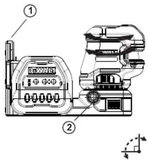
Charging the Li-ion Battery
-
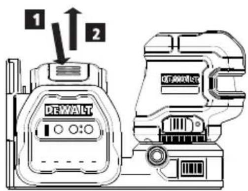
If the DEWALT12V/18V Li-ion battery pack is attached to the laser, remove it.
-
While pressing down on the release button on the battery pack (Figure ②①), pull the battery pack up to unlock it from the laser.
-
Pull the battery pack the rest of the way up and out of the laser (Figure ⑧②).
-
Plug the charger cord into an electrical outlet.
-
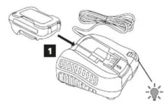
Slide the battery pack into the charger until it snaps in place (Figure A ①). On the charger, the left indicator light will flash to let you know the battery is being charged.
-
After the battery is fully-charged (the indicator light on the charger no longer flashes), press and hold the release button on the battery pack (Figure A 2) and slide the pack out of the charger (Figure A 3).
-
Slide the battery pack down in the laser until it snaps in place (Figure A 4).
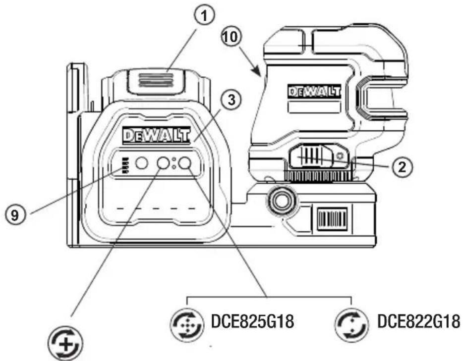
Viewing the Battery Meter
When the laser is ON, the battery meter on the keypad (Figure ⑨) indicates how much power remains.
- The bottom LED will illuminate and flash when the battery level is low (10%). The laser may continue to operate for a short time while the battery power continues to drain, but the beam(s) will quickly dim.
- After the 12V/18V Li-ion battery is charged, and the laser is turned ON again, the laser beam(s) will return to full brightness and the battery indicator level will indicate full capacity.
- If all 4 LEDs on the battery meter remain ON, this indicates that the laser is not fully powered OFF. When the laser is not in use, make sure the Power/Transport Lock switch is placed to the LEFT to the Locked/OFF position (Figure C②).
Operating Tips
- To extend battery life per charge, turn the laser off when it is not in use.
- To ensure the accuracy of your work, check the laser calibration often. Refer to Checking Laser Accuracy.
- Before attempting to use the laser, make sure it is positioned securely, on a smooth, flat stable surface that is level in both directions.
- To increase beam visibility, use a Laser Target Card (Figure N) and/or wear Laser Enhancement Glasses (Figure O) to help find the beam.

CAUTION:
To reduce the risk of serious injury, never stare directly into the laser beam with or without these glasses. Refer to Accessories for important information.
- Always mark the center of the beam created by the laser.
- Extreme temperature changes can cause movement or shifting of building structures, metal tripods, equipment, etc., which can effect accuracy. Check your accuracy often while working.
- If the laser has been dropped, check to make sure your laser is still calibrated. Refer to Checking Laser Accuracy.
Turning the Laser On
The Place the laser on a flat level surface. Slide the Power/Transport Lock switch Ⓒ ② to the right to unlock/turn ON the laser.
| Button Displays | |
 | Press once to display a horizontal laser line (Figure C 4).Press a second time to display a vertical laser line (Figure C 5).Press a third time to display a horizontal line and a vertical line (Figure C 6).Press a fourth time to stop displaying laser lines. |
 DCLE34220 DCLE34220 DCLE34520 DCLE34520 | Press once to display dots above and below the laser (Figure C 7).Press a second time to stop displaying dots. |
You can use and / together to display laser dots and lines. For example, if you press three times and once, the laser will display cross lines and two dots (Figure ⑧).
When the laser is not in use, slide the Power/Transport Lock switch to the left in the OFF/Locked position. If the Power/Transport Lock switch is not placed in the lock position, all 4 LEDs will continuously flash on the Battery Meter.
Checking Laser Accuracy
The laser tools are sealed and calibrated at the factory. It is recommended that you perform an accuracy check prior to using the laser for the first time (in case the laser was exposed to extreme temperatures) and then regularly to ensure the accuracy of your work. When performing any of the accuracy checks listed in this manual, follow these guidelines:
- Use the largest area/distance possible, closest to the operating distance. The greater the area/distance, the easier to measure the accuracy of the laser.
- Place the laser on a smooth, flat, stable surface that is level in both directions.
• Mark the center of the laser beam.
Field Calibration Check
GB
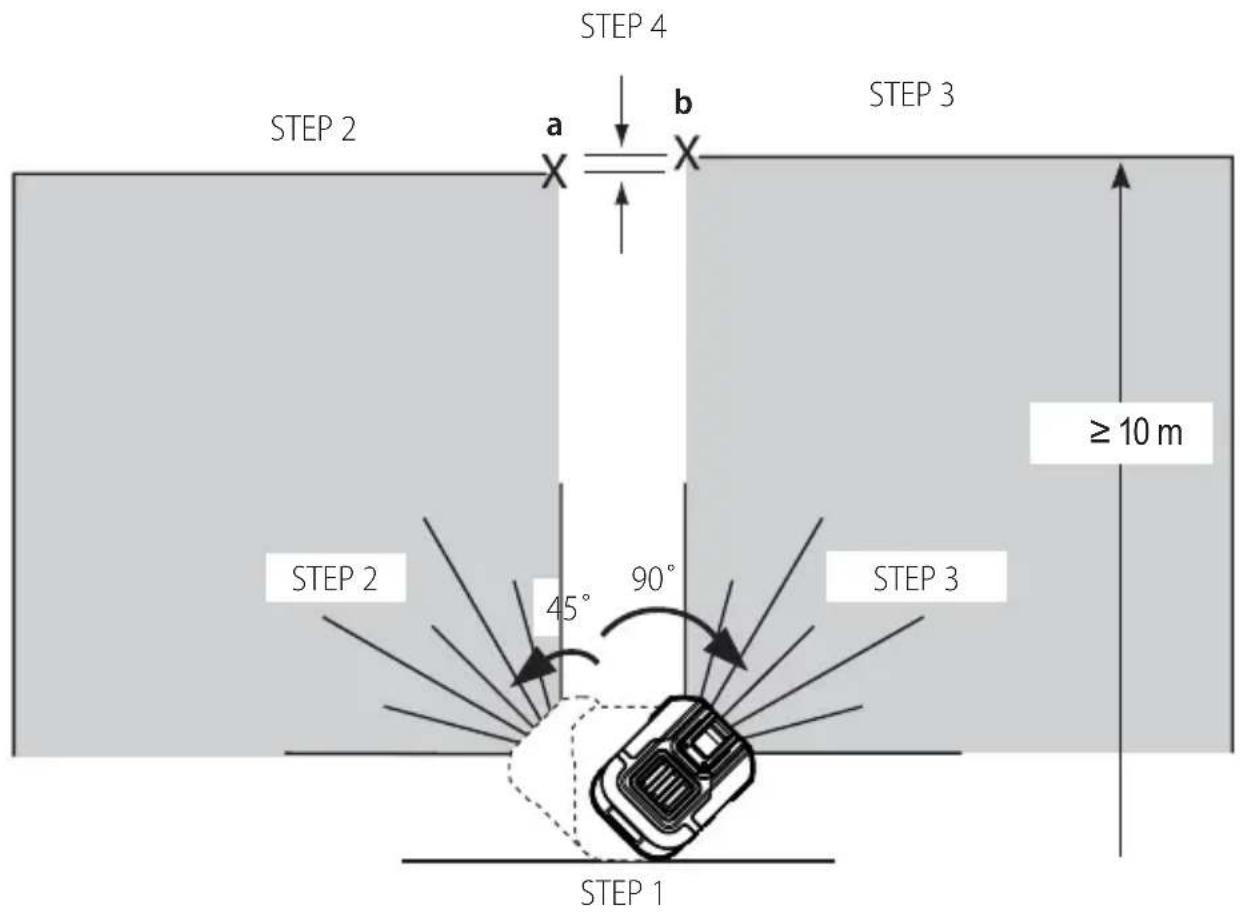
Checking Accuracy – Horizontal Beam, Scan Direction (Fig. D)
Checking the horizontal scan calibration of the laser requires two walls at least 30' (9 m) apart. It is important to conduct a calibration check using a distance no shorter than the distance of the applications for which the tool will be used.
- Attach the laser to a wall using its pivot bracket. Make sure the laser is facing straight ahead.
- Turn on the laser's horizontal beam and pivot the laser approximately 45^ so that the right-most end of the laser line is striking the opposing wall at a distance of at least 30' (9 m). Mark the center of the beam (a).
- Pivot the laser approximately 90^ to bring the left-most end of the laser line around to the mark made in Step 2. Mark the center of the beam (b).
- Measure the vertical distance between the marks.
- If the measurement is greater than the values shown below, the laser must be serviced at an authorized service center.
| Distance Between Walls | Allowable Distance Between a and b |
| 10.0 m 3.0 mm | |
| 12.0 m 3.6 mm | |
| 15.0 m 4.5 mm |
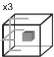
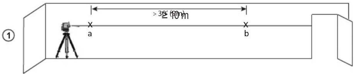
^1 Checking Accuracy – Horizontal Beam, Pitch Direction (Fig. E)
Checking the horizontal pitch calibration of the laser requires a single wall at least 30' (9 m) long. It is important to conduct a calibration check using a distance no shorter than the distance of the applications for which the tool will be used.
- Attach the laser to one end of a wall using its pivot bracket.
GB
- Turn on the laser's horizontal beam and pivot the laser toward the opposite end of the wall and approximately parallel to the adjacent wall.
- Mark the center of the beam at two locations (a, b) at least 30' (9m) apart.
- Reposition the laser to the opposite end of the wall.
- Turn on the laser's horizontal beam and pivot the laser back toward the first end of the wall and approximately parallel to the adjacent wall.
- Adjust the height of the laser so that the center of the beam is aligned with the nearest mark (b).
- Mark the center of the beam (c) directly above or below the farthest mark (a).
- Measure the distance between these two marks (a, c).
- If the measurement is greater than the values shown below, the laser must be serviced at an authorized service center.
| Distance Between Walls | Allowable Distance Between a and c |
| 10.0 m 6.0 mm | |
| 12.0 m 7.2 mm | |
| 15.0 m 9.0 mm |
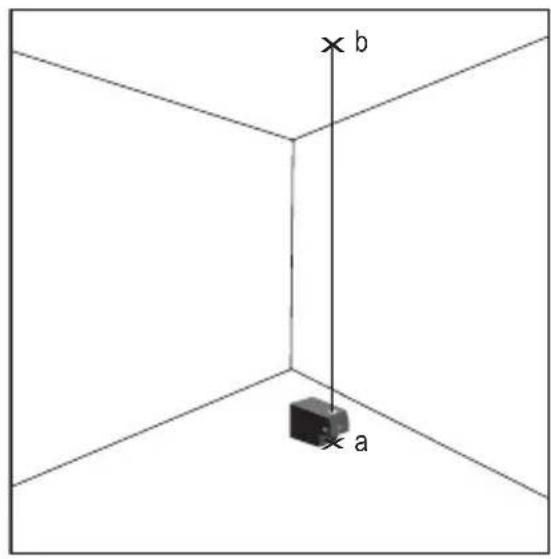
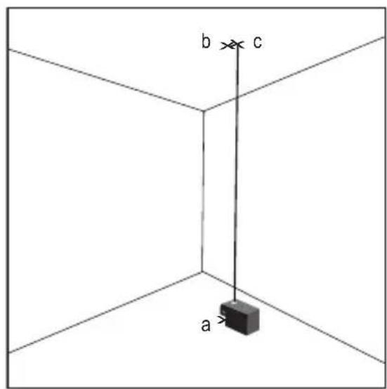
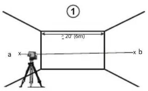
Checking Accuracy – Vertical Beam (Fig. F)
Checking the vertical (plumb) calibration of the laser can be most accurately done when there is a substantial amount of vertical height available, ideally 20' (6m), with one person on the floor positioning the laser and another person near a ceiling to mark the position of the beam. It is important to conduct a calibration check using a distance no shorter than the distance of the applications for which the tool will be used.
- Start by marking a 5' (1.5 m) line on the floor.
-
Turn on the laser's vertical beam and position the unit at one end of the line, facing the line.
-
Adjust the unit so its beam is aligned and centered on the line on the floor.
- Mark the position of the laser beam on the ceiling (a). Mark the center of the laser beam directly over the midpoint of the line on the floor.
- Reposition the laser at the other end of the line on the floor. Adjust the unit once again so its beam is aligned and centered on the line on the floor.
- Mark the position of the laser beam on the ceiling (b), directly beside the first mark (a).
- Measure the distance between these two marks.
- If the measurement is greater than the values shown below, the laser must be serviced at an authorized service center.
- Ceiling Allowable Distance Between Marks Height 2,5 m.
| Distance Between Walls | Allowable Distance Between a and b |
| 2.5 m 1.7 mm | |
| 3.0 m 2.1 mm | |
| 4.0 m 2.8 mm | |
| 6.0 m 4.1 mm |
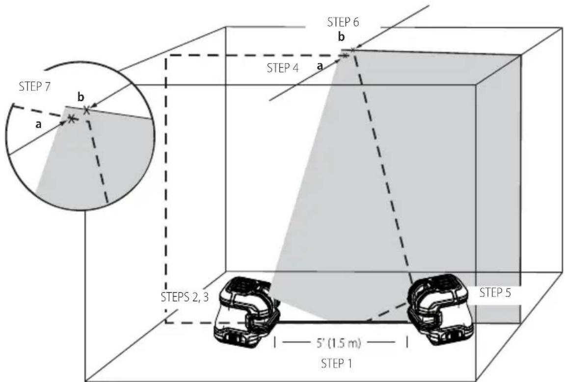
Plumb Dot Accuracy
Checking the plumb calibration of the laser can be most accurately done when there is a substantial amount of vertical height available, ideally 20' (6 m), with one person on the floor positioning the laser and another person near a ceiling to mark the dot created by the beam on the ceiling.
- Mark point (a) on the floor, as shown in Figure ⑤①.
- Turn the laser ON and press once to display dots above and below the laser.
- Place the laser so that the down dot is centered over point (a) and mark the center of the up dot on the ceiling as point (b) (Figure ⑤①).
-
Turn the laser 180^ , making sure that the down dot is still centered on point (a) on the floor (Figure ⑤ ②).
-
Mark the center of the up dot on the ceiling as point (c) (Figure ⑤ ②).
• Measure the distance between points (b) and (c). - If your measurement is greater than the Allowable Distance Between (b) & (c) for the corresponding Distance Between Ceiling & Floor in the following table, the laser must be serviced at an authorized service center.
| Distance Between Ceiling & Floor | Allowable Distance Between ⓑ & Ⓒ |
| 2.5 m 1.7 mm | |
| 3.0 m 2.1 mm | |
| 4.0 m 2.8 mm | |
| 6.0 m 4.1 mm |
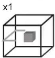
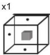
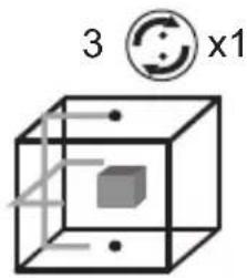
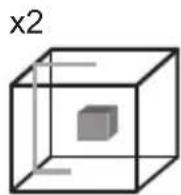
Level Dot Accuracy - Level
Checking the level calibration of the laser unit requires two parallel walls at least 20' (6 m) apart.
- Turn the laser ON and press twice to display dots above, ahead, below, and to the right and left of the laser.
- Place the laser 2"-3" (5–8 cm) from the first wall. To test the front laser dot, make sure the front of the laser is facing the wall (Figure H #1).
- Mark the laser dot position on the first wall as point (a) (Figure H #1).
- Turn the laser 180^ and mark the laser dot position on the second wall as point (b) (Figure H #1).
- Place the laser 2"-3" (5–8 cm) from the second wall. To test the front laser dot, make sure the front of the laser is facing the wall (Figure H #2), and adjust the height of the laser until the laser dot hits point b.
- Turn the laser 180^ and aim the laser dot near point (a) on the first wall, and mark point (c) (Figure H #2).
- Measure the vertical distance between points (a) and (c) on the first wall.
- If your measurement is greater than the Allowable Distance Between (a) & (c) for the corresponding Distance Between Walls in the following table, the laser must be serviced at an authorized service center.
- Repeat steps 2 through 8 to check the accuracy of the right dot and then the left dot, making sure that the laser dot you are testing is the laser dot facing each wall.
| Distance Between Walls | Allowable Distance Between a & c |
| 6.0 m 4.1 mm | |
| 9.0 m 6.2 mm | |
| 15.0 m 10.2 mm |
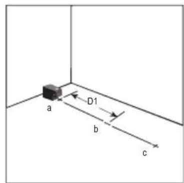
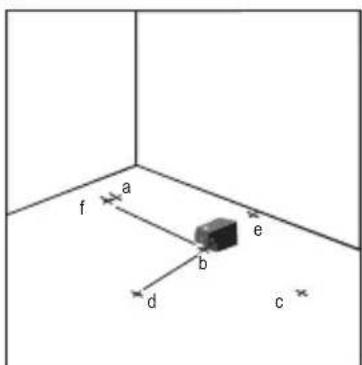
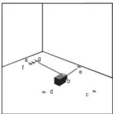
Level Dot Accuracy - Square
Checking the level calibration of the laser unit requires a room at least 20' (6 m) long. All marks can be made on the floor by placing a target in front of the level or square beam and transferring the location to the floor.
NOTE: To ensure accuracy, the distance (D1) from (a) to (b), (b) to (c), (b) to (d), and (b) to (e) should be equal.
- Turn the laser ON and press once to display dots above, ahead, and below the laser.
- Mark point (a) on the floor at one end of the room, as shown in Figure I #1.
- Place the laser so that the down dot is centered over point (a) and make sure the front dot points toward the far end of the room (Figure I #1).
- Using a target to transfer the front level dot location on the wall to the floor, mark point (b) on the floor and then point (c) on the floor (Figure I #1).
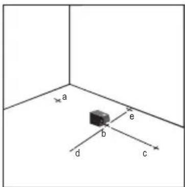
- Move the laser to point (b) and align the front level dot to point c again (Figure I #2).
- Using a target to transfer the front level dot location on the wall to the floor, mark the location of two square beams as points (d) and (e) on the floor (Figure I #2).
GB
- Turn the laser 90^ so the front level dot aligns to point e (Figure I #3).
- Mark the location of the first square beam as point (f) on the floor as close as possible to point (a) (Figure I #3).
- Measure the distance between points (a) and (f) (Figure I #3).
- If your measurement is greater than the Allowable Distance Between (a) and (f) for the corresponding Distance (D1) in the following table, the laser must be serviced at an authorized service center.
- Turn the laser 180^ so the front level dot aligns to point e (Figure I #4).
- Mark the location of the second square beam as point (g) on the floor as close as possible to point (a) (Figure I #4).
- Measure the distance between points (a) and (g) (Figure I #4).
- If your measurement is greater than the Allowable Distance Between (a) & (g) for the corresponding Distance (D1) in the following table, the laser must be serviced at an authorized service center.
| Distance (D1) Allowable Distance Betweena & f or a & g | |
| 6.0 m 5.3 mm | |
| 9.0 m 7.9 mm | |
| 15.0 m 13.1 mm | |
Using the Laser
Leveling the Laser
As long as the laser is properly calibrated, the laser is self-leveling. Each laser is calibrated at the factory to find level as long as it is positioned on a flat surface within average ±4^ of level. No manual adjustments are required.
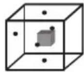
If the laser has been tilted so much that it cannot self-level ( >4^ ), the laser beam will flash. There are two flashing sequences associated with the out of level condition.
- Between 4^ and 10^ the beams flash with a constant blink cycle
- At angles greater than 10^ the beams flash with a three blink cycle.
When the beams flash THE LASER IS NOT LEVEL (OR PLUMB) AND SHOULD NOT BE USED FOR DETERMINING OR MARKING LEVEL OR PLUMB. Try repositioning the laser on a more level surface.
Using the Pivot Bracket
The laser has a magnetic pivot bracket (Figure ①①) permanently attached to the unit.

WARNING:
Position the laser and/or wall mount on a stable surface. Serious personal injury or damage to the laser may result if the laser falls.
- The bracket has a keyhole slot (Figure K) so it can be hung from a nail or screw on any kind of surface.
- The bracket has a fine adjustment knob (Figure ① ②) to help you line up the laser beams. Place the unit on a flat level surface and turn the knob to the right to move the beams to the right, or turn the knob to the left to move the beams to the left.
- The bracket has magnets (Figure ①) which allow the unit to be mounted to most upright surfaces made of steel or iron. Common examples of suitable surfaces include steel framing studs, steel door frames, and structural steel beams. Before attaching the pivot bracket against a stud (Figure ②), place the Metal Enhancement Plate (Figure ③) on the opposite side of the stud.
Maintenance
- To maintain the accuracy of your work, check the laser often to make sure it is properly calibrated. See Field Calibration Check.
- Calibration checks and other maintenance repairs may be performed by DEWALT service centers.
- When not in use, store the laser in the kit box provided. Do not store your laser at temperatures below -20 °C or above 60 °C.
- Do not store your laser in the kit box if the laser is wet. The laser should be dried first with a soft dry cloth prior to storage.
Cleaning
Exterior plastic parts may be cleaned with a damp cloth. Although these parts are solvent resistant, NEVER use solvents. Use a soft, dry cloth to remove moisture from the tool before storage.
Troubleshooting
The Laser Does Not Turn On
- Fully-charge the battery pack and then reinstall it in the laser unit.
- If the laser unit is heated above 120 °F (50 °C), the unit will not turn on. If the laser has been stored in extremely hot temperatures, allow it to cool. The laser level will not be damaged by pressing the on/off button before cooling to its proper operating temperature.
The Laser Beams Flash
The lasers are designed to self-level up to an average of 4^ in all directions. If the laser is tilted so much that the internal mechanism cannot level itself, the laser beams will flash indicating that the tilt range has been exceeded. THE FLASHING BEAMS CREATED BY THE LASER ARE NOT LEVEL OR PLUMB AND
SHOULD NOT BE USED FOR DETERMINING OR MARKING LEVEL OR PLUMB. Try repositioning the laser on a more level surface.
The Laser Beams Will Not Stop Moving
The laser is a precision instrument. Therefore, if it is not positioned on a stable (and motionless) surface, the laser will continue to try to find level. If the beam will not stop moving, try placing the laser on a more stable surface. Also, try to make sure that the surface is relatively flat, so that the laser is stable.
The Battery Meter LEDs Flash
When all 4 LEDs continuously flash on the Battery Meter this indicates that the unit has not been fully powered off using the Power/Transport Lock switch (Figure ②). The Power/Transport Lock switch should always be placed in the LOCKED/OFF position when the laser is not in use.
Accessories
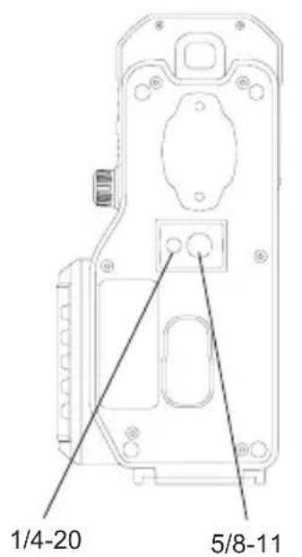
The laser is equipped with both 1/4 - 20 and 5/8 - 11 female threads on the bottom of the unit (Figure M). This thread is to accommodate current or future DEWALT accessories. Only use DEWALT accessories specified for use with this product. Follow the directions included with the accessory.

WARNING:
Since accessories, other than those offered by DEWALT, have not been tested with this product, use of such accessories with this tool could be hazardous. To reduce the risk of injury, only DEWALT recommended accessories should be used with this product.
If you need any assistance in locating any accessory, please contact your nearest DEWALT service center or go to www.2helpU.com.
GB
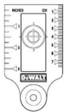
Target Card
Some laser kits include a Laser Target Card (Figure Ⓞ) to aid in locating and marking the laser beam. The target card enhances the visibility of the laser beam as the beam crosses over the card. The card is marked with standard and metric scales. The laser beam passes through the red plastic and reflects off of the reflective tape on the reverse side. The magnet at the top of the card is designed to hold the target card to ceiling track or steel studs to determine plumb and level positions. For best performance when using the Target Card, theDEWALT logo should be facing you.
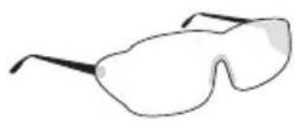
Laser Enhancement Glasses
Some laser kits include Laser En hancement Glasses (Figure P). These glasses improve the visibility of the laser beam under bright light conditions or over long distances when the laser is used for interior applications. These glasses are not required to operate the laser.

CAUTION:
These glasses are not ANSI approved safety glasses and should not be used while operating other tools. These glasses do not keep the laser beam from entering your eyes.

CAUTION:
To reduce the risk of serious injury, never stare directly into the laser beam with or without these glasses.
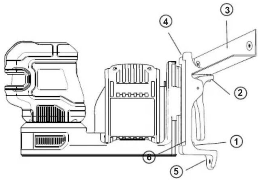
Ceiling Mount
The laser ceiling mount (Figure ①), if included, offers more mounting options for the laser. The ceiling mount has a clamp (Figure ②) at one end which can be fixed to a wall angle for acoustic ceiling installation (Figure ③). At each end of the ceiling mount is a screw hole (Figure ④ and ⑤), allowing the ceiling mount to be attached to any surface with a nail or screw.
Once the ceiling mount is secured, its steel plate provides a surface to which the magnetic pivot bracket (Figure N 6) can be attached. The position of the laser can then be fine-tuned by sliding the magnetic pivot bracket up or down on the wall mount.
Service and Repairs
NOTE: Disassembling the laser level(s) will void all warranties on the product.
To assure product SAFETY and RELIABILITY, repairs, maintenance and adjustment should be performed by authorized service centers. Service or maintenance performed by unqualified personnel may result in a risk of injury. To locate your nearest DEWALT service center go to www.2helpU.com.
Warranty
Go to www.2helpU.com for the latest warranty information.
Specifications
GB
| DCE822G18 / DCE825G18 | |
| Light Source Laser diodes | |
| Laser Wavelength 510 – 530nm visible | |
| Laser Power ≤1.0 mW CLASS 2 LASER PRODUCT | |
| Working Range 85 m (280') | 100 m (330') with detector (sold separately) |
| Accuracy - all lines and dots, except down dot | ±3.0 mm per 10 m |
| Battery Low 1 LED Flashing on Battery meter | |
| Unit Not Powered Off With Pendulum Lock Switch | 4 LEDs Flashing on Battery meter |
| Flashing Laser Beams Tilt range exceeded/unit is not level | |
| Power Source | DEWALT12V or 18V Battery Pack |
| Operating Temperature | 4 °C to 40 °C (39.2 °F to 104 °F) |
| Storage Temperature | 4 °C to 40 °C (39.2 °F to 104 °F) |
| Humidity | "Maximum 80% for temperatures up to 31 °C (88 °F), decreasing linearly to 50% relative humidity at 40 °C (104 °F)" |
| Environmental Water & Dust Resistant to IP54 | |
| Altitude | < 2000 m (6500') |
Inhalt
D
| Distanza tra pareti | Distanza consentita tra a e b |
| 10,0 m 3,0 mm | |
| 12,0 m 3,6 mm | |
| 15,0 m 4,5 mm |
| Distanza tra pareti | Distanza consentita tra a and c |
| 10,0 m 6,0 mm | |
| 12,0 m 7,2 mm | |
| 15,0 m 9,0 mm |
| Distanza (D1) Distanza consentita tra | |
| a e f o a e g | |
| 6,0 m 5,3 mm | |
| 9,0 m 7,9 mm | |
| 15,0 m 13,1 mm | |
| Distância entre as paredes | Distância permissível entre a and c |
| 10,0 m 6,0 mm | |
| 12,0 m 7,2 mm | |
| 15,0 m 9,0 mm |
Verificar o rigor – feixe vertical (Fig. F)
Laservermogen ≤1,0 mW KLASSE 2 LASERPRODUCT
DEWALT12V of 18V Accu
| Batteritype Batteripakke | |
| 12V DCB1 | 20, DCB121, DCB122,DCB123, DCB124, DCB124G,DCB125, DCB126, DCB126G,DCB127 |
| 18V DCB1 | 181, DCB182, DCB183,DCB183B, DCB183G, DCB184,DCB184B, DCB184G, DCB185,DCB187, DCB189, DCBP034,DCBP518 |
© 2020, 2022 D EWALT Industrial Tool Co.
DEWALT EU, Black- & Decker-Strasse 40, 65510 Idstein, Germany DEWALT UK, 270 Bath Rd, Slough SL1 4DX, England
NA129074 June 2022