DCE074R - Laser pointer DEWALT - Free user manual and instructions
Find the device manual for free DCE074R DEWALT in PDF.
Download the instructions for your Laser pointer in PDF format for free! Find your manual DCE074R - DEWALT and take your electronic device back in hand. On this page are published all the documents necessary for the use of your device. DCE074R by DEWALT.
USER MANUAL DCE074R DEWALT
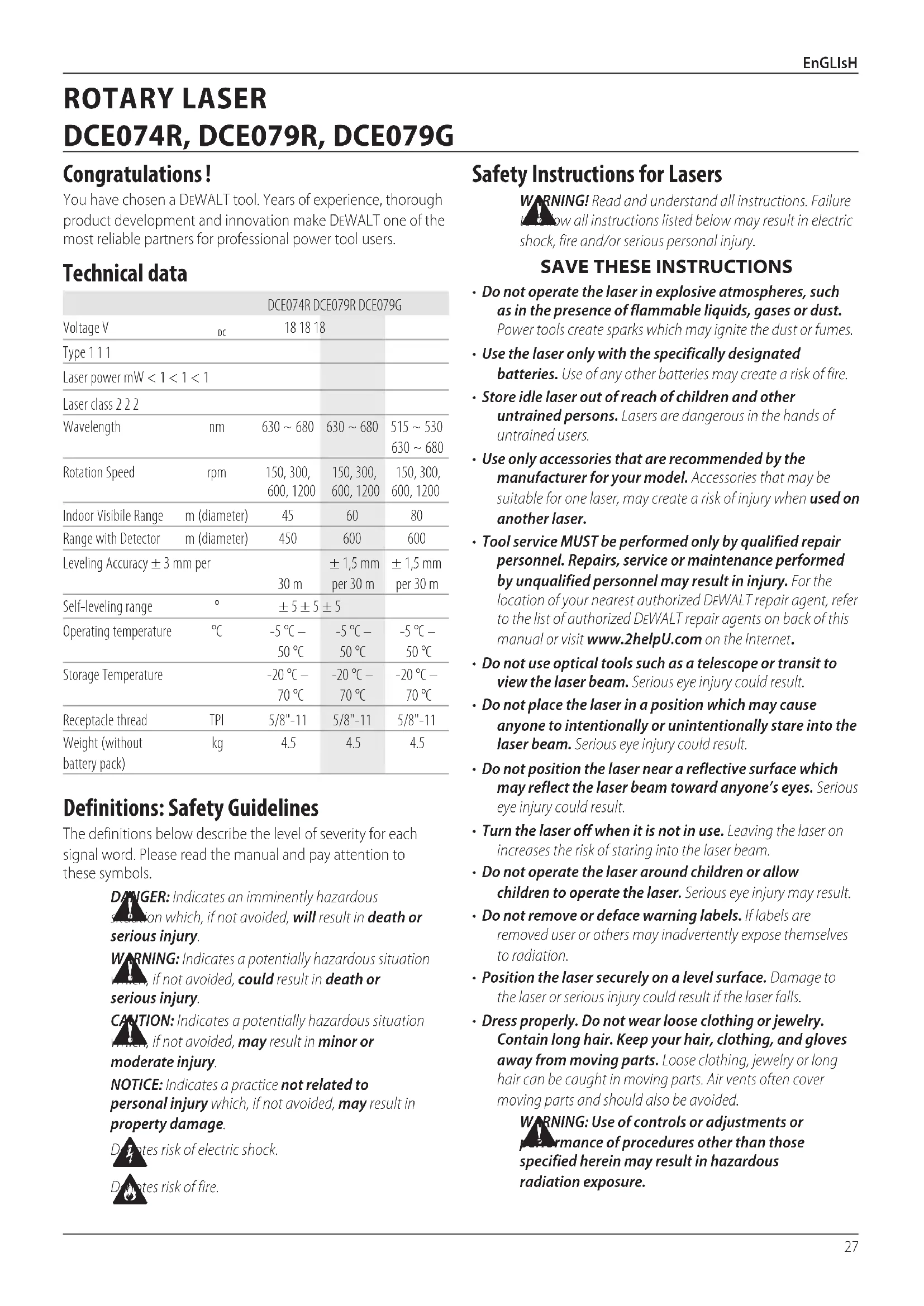
WARNING! Read and understand all instructions. Failure to follow all instructions listed below may result in electric shock, fire and/or serious personal injury.
SAVE THESE INSTRUCTIONS
- Do not operate the laser in explosive atmospheres, such as in the presence of flammable liquids, gases or dust. Power tools create sparks which may ignite the dust or fumes.
- Use the laser only with the specifically designated batteries. Use of any other batteries may create a risk of fire.
- Store idle laser out of reach of children and other untrained persons. Lasers are dangerous in the hands of untrained users.
- Use only accessories that are recommended by the manufacturer for your model. Accessories that may be suitable for one laser, may create a risk of injury when used on another laser.
- Tool service MUST be performed only by qualified repair personnel. Repairs, service or maintenance performed by unqualified personnel may result in injury. For the location of your nearest authorized DeWALT repair agent, refer to the list of authorized DeWALT repair agents on back of this manual or visit www.2helpU.com on the Internet.
- Do not use optical tools such as a telescope or transit to view the laser beam. Serious eye injury could result.
- Do not place the laser in a position which may cause anyone to intentionally or unintentionally stare into the laser beam. Serious eye injury could result.
- Do not position the laser near a reflective surface which may reflect the laser beam toward anyone’s eyes. Serious eye injury could result.
- Turn the laser off when it is not in use. Leaving the laser on increases the risk of staring into the laser beam.
- Do not operate the laser around children or allow children to operate the laser. Serious eye injury may result.
- Do not remove or deface warning labels. If labels are removed user or others may inadvertently expose themselves to radiation.
- Position the laser securely on a level surface. Damage to the laser or serious injury could result if the laser falls.
- Dress properly. Do not wear loose clothing or jewelry. Contain long hair. Keep your hair, clothing, and gloves away from moving parts. Loose clothing, jewelry or long hair can be caught in moving parts. Air vents often cover moving parts and should also be avoided.
WARNING: Use of controls or adjustments or
performance of procedures other than those specified herein may result in hazardous radiationexposure. Congratulations ! You have chosen a DeWALT tool. Years of experience, thorough product development and innovation make DeWALT one of the most reliable partners for professional power toolusers. Technical data
DANGER: Indicates an imminently hazardous
situation which, if not avoided, will result in death or seriousinjury.
WARNING: Indicates a potentially hazardous situation
which, if not avoided, could result in death or seriousinjury.
CAUTION: Indicates a potentially hazardous situation which, if not avoided, may result in minor or moderateinjury. NOTICE: Indicates a practice not related to personal injury which, if not avoided, may result in propertydamage.
Denotes risk of electricshock.
Denotes risk offire. English (original instructions) ROTARY LASER
WARNING! DO NOT DISASSEMBLE THE LASER. There are no user serviceable parts inside. Disassembling the laser will void all warranties on the product. Do not modify the product in any way. Modifying the tool may result in hazardous laser radiation exposure.
contacts of a removed battery. Additional Safety Instructions for Lasers
- This laser complies with class 2 according to IEC/EN 60825- 1:2014. Do not replace a laser diode with a different type. If damaged, have the laser repaired by an authorised repairagent.
- Do not use the laser for any purpose other than projecting laser lines.
- An exposure of the eye to the beam of a class 2 laser is considered safe for a maximum of 0.25 seconds. Eyelid reflexes will normally provide adequate protection.
- Never look into the laser beam directly and intentionally.
- Do not use optical tools to view the laser beam.
- Do not set up the tool at a position where the laser beam can cross any person at headheight.
- Do not let children come in contact with the laser. Residual Risks The following risks are inherent to the use of this device:
- injuries caused by staring into laser beam. Labels on tool The following pictographs are shown on the tool: Read the instruction manual before use. Laser warning. Do not stare into the laser beam. Date Code Position The date code, which also includes the year of manufacture, is printed into the housing. Example: 2016 XX XX Year of Manufacture Important Safety Instructions for All Battery Packs When ordering replacement battery packs, be sure to include catalog number and voltage. Consult the chart at the end of this manual for compatibility of chargers and battery packs. The battery pack is not fully charged out of the carton. Before using the battery pack and charger, read the safety instructions below. Then follow charging procedures outlined.
- This DeWALT rotary laser will accept all DeWALT 18 volt lithium ion batteries, but is built to best resist damage during a fall when used with the following batteries: All 1.5Ah & 2Ah DeWALT 18 volt lithium ion batteries.
- Consult the chart at the end of this manual for compatibility of chargers and battery packs.
- Refer to Battery Safety Manual for safety instructions. Battery Installation / Removal and Charging To install battery pack (Fig. A) Using the 18V DeWALT Rechargeable Pack:
- Install the 18V DeWALT Rechargeable Battery pack as shown in Figure A.
1. Depress the battery release button
2. Slide the battery pack into the track firmly.
3. Release the battery release button on the battery.
To Remove the battery pack
1. Depress the battery release button on the battery.
2. Slide the battery pack out of the track
3. Release the battery release button on the battery.
4. To recharge the battery pack, insert it into the charger as
described in the Battery Safety Manual.
WARNING: Batteries can explode, or leak, and can cause
injuryor fire. To reduce this risk. Refer to Battery Safety Manual for safety instructions. Storage Recommendations
1. The best storage place is one that is cool and dry, away from
direct sunlight and excess heat or cold.
2. Long storage will not harm the battery pack or charger.
Under proper conditions, they can be stored for 5 years ormore.29 ENGLISH
SAVE THESE INSTRUCTIONS FOR FUTURE USE
Chargers Your tool uses a DeWALT 18 Volt charger. Be sure to read all safety instructions before using your charger. Consult the chart at the end of this manual for compatibility of chargers and battery packs.
- DO NOT attempt to charge the battery pack with any chargers other than the ones in this manual. The charger and battery pack are specifically designed to work together.
- Carefully follow all instructions and warnings on the battery label and package and accompanying Battery Safety Manual. Personal Safety
- Stay alert, watch what you are doing and use common sense when operating a laser product. Do not use tool while tired or under the influence of drugs, alcohol, or medication. A moment of inattention while operating laser products may result in serious personal injury.
- Use appropriate personal protective equipment including eye proection when working in a construction environment. Tool Use and Care
- Do not use tool if switch does not turn it on or off. Any tool that cannot be controlled with the switch is dangerous and must berepaired.
- Store idle laser products out of the reach of children and do not allow persons unfamiliar with the laser product or these instructions to operate the laser product. Laser products are dangerous in the hands of untrained users.
- Use only accessories that are recommended by the manufacturer for your model. Accessories that may be suitable for one tool, may become hazardous when used on another tool. Service
- Have your laser product serviced by a qualified repair person using only identical replacement parts. This will ensure that the safety of the laser product is maintained. Description
WARNING: Never modify the power tool or any part of it.
Damage or personal injury could result. Laser (Fig. A–D)
Axis selection button
Battery release button
Down/Clockwise Button Intended Use The DCE074R/DCE079R/DCE079G rotary laser has been designed to project laser lines to aid in professional applications. The tool can be used both inside and outside for horizontal (level) and vertical (plumb) alignment. The tool can also produce a stationary laser dot that can be directed manually to establish or transfer a mark. The applications range from drop- ceiling installation and wall layout to foundation leveling and deck building. DO NOT use under wet conditions or in presence of flammable liquids or gases. This laser is a professional tool. DO NOT let children come into contact with the tool. Supervision is required when inexperienced operators use this tool.
- This product is not intended for use by persons (including children) suffering from diminished physical, sensory or mental abilities; lack of experience, knowledge or skills unless they are supervised by a person responsible for their safety. Children should never be left alone with thisproduct.
ASSEMBLY AND ADJUSTMENT
WARNING: Do not place the laser in a position
which may cause anyone to intentionally or unintentionally stare into laser beam. Serious eye injury may result from staring at the beam. Setting Up the Laser The laser facilitates various set-ups, making it useful for severalapplications. Manual Head Rotation The laser is designed with a protective alloy cage around the rotary head to prevent accidental damage from work site activities. You can still direct the beam to establish or transfer a mark by pressing the scan mode once and jogging the dot using the Clockwise/counter clockwise buttons.30 ENGLISH Wall Set-up (Fig. C, M) The wall mount is used for mounting the laser to a wall track to aid in drop ceiling installation and other specialty levellingprojects.
CAUTION: Before attaching the laser level to wall track or ceiling angle, be sure that the track or angle is properlysecured.
1. Place the laser on the mounting base
aligning the 5/8-11 screw hole on the tripod adapter (
, Fig. C) attached to the bottom of the laser with the hole
in the mounting base. Turn the mounting knob
to secure the laser.
2. With the wall mount measuring scale
facing you, loosen the wall mount clamp locking knob
to open the clampjaws.
3. Position the clamp jaws around the wall track or ceiling
angle and tighten the wall mount clamp locking knob
to close the clamp jaws onto the track. Be sure that the wall mount clamp locking knob is securely tightened beforeproceeding.
CAUTION: Always use a ceiling wire hanger or equivalent material, in addition to the wall mount clamp locking knob, to help secure the laser level while mounting it to a wall. Thread the wire through the handle of the laser level. DO NOT thread the wire through the protective metal cage. Additionally, screws may be used to fasten the wall mount directly to the wall as a back-up. Screw holes
are located at the top of the wall mount.
, approximate a level position from the wall.
5. The laser can be adjusted up and down to the desired offset
height for working. To change the height, loosen the locking knob
located on the left of the wall mount.
6. Turn the adjustment knob
, located to the right of the wall mount, to move the laser level up and down to set your height. Use the wall mount measuring scale
to pinpoint your mark. NOTE: It may be helpful to turn the power on and turn the rotary head so that it puts a dot on one of the laser scales. The DeWALT target card is marked at 38mm, therefore, it may be easiest to set the offset of the laser to 38mm below thetrack.
7. Once you have positioned the laser at the desired height,
to maintain this position. Tripod Set-up (Fig. C)
1. Position the tripod securely and set it to the desired height.
2. Make sure that the top of the tripod is roughly level. The
laser will self-level only if the top of the tripod is within ± 5˚ of level. If the laser is set up too far out of level, it will beep when it reaches the limit of its leveling range. No damage will be done to the laser, but it will not operate in an “out of level” condition.
3. Secure the laser to the tripod by attaching the tripod
as shown in Figure C to the laser body. The adapter may be assembled to the bottom for level mode
or to the side for plumb mode
. Place the assembly on the tripod and screw the threaded knob on the tripod into the female thread on the tripod adapter. NOTE: Be sure that the tripod you are working with has a 5/8"–11 threaded screw to ensure secure mounting.
4. Turn the laser on and adjust the rotation speed and controls
as desired. Floor set-up (Fig. D) The laser level can be positioned directly on the floor for leveling and plumbing applications such as framing walls.
1. Place the laser on a relatively smooth and level surface
where it will not be disturbed.
2. Position the laser for a level
3. Turn the laser on and adjust the rotation speed and controls
as desired. NOTE: The laser will be easier to set up for wall applications if the rotation speed is set to 0 rpms and if the remote control is used to line up the laser with control marks. The remote allows one person to set up the laser. OPERATION
WARNING! Do not place the laser in a position which may cause anyone to intentionally or unintentionally stare into the laser beam. Serious eye injury may result from staring at the beam. Instructions for Use
WARNING: Always observe the safety instructions and
applicable regulations.
- To extend battery life per charge, turn the laser off when it is not in use.
- To ensure the accuracy of your work, check the laser calibration often. Refer to Field Callibration Check under Laser Maintenance.
- Before attempting to use the laser, make sure the tool is positioned on a relatively smooth, secure surface.
- Always mark the centre of the laser line or dot. If you mark different parts of the beam at different times you will introduce error into your measurements.
- To increase working distance and accuracy, set up the laser in the middle of your working area.
- When attaching to a tripod or wall, mount the lasersecurely.
- When working indoors, a slow rotary head speed will produce a visibly brighter line; a faster rotary head speed will produce a visibly solid line.
- To increase beam visibility, wear Laser Enhancement Glass es and/or use a Laser Target Card to help find the beam.
- Extreme temperature changes can cause movement or shifting of building structures, metal tripods, equipment, etc., which can affect accuracy. Check your accuracy often while working.31 ENGLISH
- When working with the DeWALT Digital Laser Detector, set the laser’s rotation speed to the fastestsetting.
- If the laser is dropped or suffers a sharp blow, have the calibration system checked by a qualified service centre before using the laser. Laser Control Panel (Fig.B) The laser is primarily controlled by the power button
and the scan mode button
, These features are subsequently modified using the Axis selection button
(DCE079R/G only), and two direction/ elevation adjustment buttons (
). The direction/elevation adjustment buttons control the rotational direction of the laser head as well as adjust the elevation of the beam when the unit is in slopemode. Four LED indicator lights are on the control panel: power
(DCE079R/G only), Y-axis leveling
(DCE079R/G only) and Hi mode (anti drift)
1. Insert the fully charged 18V battery pack as shown in
2. Gently press the power button
to power the laser on. - The power LED indicator light
will illuminate and the unit will self level. The beam rotates once level at the default settings of 600 RPM in the clockwisedirection. - Self leveling mode is activated automatically after the unit is powered on. - Hi Mode (Anti- Drift) is activated automatically after 10 sec. The Hi LED
will illuminate when active. - Press the speed/rotation button
to adjust the rotation speed. The direction can be changed using buttons
Turning the Laser Off Press the the power button for 3 sec to turn the laser off. The power LED indicator light will no longer be illuminated. Laser Control Panel Buttons (Fig, B, J) Power Button To completely power the laser unit off, the power button on the control panel of the laser unit must be pressed for 3 sec. The laser unit will also automatically power off if it is left in Sleep Mode for 8 hours. NOTE: Press the remote control power button to put the laser unit into Sleep Mode. In Sleep Mode all laser unit functions shut off except for a periodic blink from the power LED on the control panel of the laser unit. Press the remote control power button again to “wake up” the laser unit. Speed/Rotation Button The speed button
is used to adjust the rotation speed of the laser beam through its 4 preset speeds. The head speed will cycle through 4 speeds, then repeat the sequence as the speed/rotation button is pressed. NOTE: The speed/rotation button performs the same function as the speed/rotation button on the remote control. Scan Mode Button 15˚/45˚/90˚ The scan mode button
is used to make the laser head sweep back and forth, creating a short, bright laser line. This short line is much brighter and more visible than when the unit is in full rotation mode. Using Scan Mode:
- To enter Scan Mode, push and release the scan mode button
. To cycle through the scan angles, continue to press the button until you reach the angle desired. Repeat the sequence to change angles.
- The direction of the scan zone can be controlled with the arrow buttons (
- To return to self leveling mode and re-engage full self- leveling, press and hold the mode button
again. Setting the Slope Direction When Slope Mode is activated, the unit automatically engages the X- Axis. This allows the operator to slope the laser in the direction of the X-Axis, as indicated by the “gunsights” on therollcage. The LED indicator light on the laser unit control panel (Fig. B,
) will indicate the slope direction that is selected. The selected axis is identified by LED lights
DCE079R/G only: In certain situations, it may be desirable to slope the laser in the Y-axis. The direction of Slope Mode can be changed back and forth between the Y- and X-axes by pressing the X-Y axis button
on the keypad. Setting the Amount of Slope Once Slope Mode is activated and the desired axis is active the amount of slope can be adjusted as follows:
- Use the laser control panel up and down arrow buttons (Fig.B,
) to tilt the laser rotor head up and down. Arrow Buttons (Fig. J) The arrow buttons (
) are used for different functions depending on the operating mode of the laser unit. In Self-Leveling Horizontal Mode: the arrows buttons adjust the direction of the laser beam clockwise or counter clockwise during rotation or Scan Mode. In Self-Leveling Vertical Mode: the arrow buttons move the laser beam left and right.32 ENGLISH In Slope Mode: the arrow buttons are used to tilt the laserhead. Height of Instrument Alert The DCE074R and DCE079R/G have a built-in alarm feature that alerts the operator if the unit is disturbed after the unit has self- leveled. The laser unit will stop rotating, the control panel LED indicator light will flash and the beeper will sound. To Reset The Laser Unit for Continued Use
- Turn the unit off and back on again using the power button on the laser unit control panel. NOTE: Always recheck the laser setup after the Height of Instrument Alert (Hi mode) has triggered. Using the Remote Control (Fig.B,E) (DCE079R/G) The remote control allows one person to operate and setup the laser from a distance. The remote control features a power/slope mode button
, two arrows (rotation direction and tilt angle)
and axis selection button
. The LED light indicates a signal is being transmitted. Remote Control: Mode Button Press the remote control mode button
to put the laser unit into Scan Mode. In Scan Mode all laser unit functions shut off except for a periodic blink from the power LED
on the control panel of the laser unit. Press the remote control power button again to “wake up” the laser unit. NOTE: To completely power the laser unit off, the power button on the control panel of the laser unit must be pressed. The laser unit will also automatically power off if it is left in Sleep Mode for 8 hours. Remote Control: Mode Buttons The Rotary Laser defaults to clockwise rotation of 360° at 600 RPM when powered on. Speed can be cycled through the available RPM selections using the SPEED button
. To return to self-leveling mode and re-engage full self- leveling, press and hold the mode button
again . Setting the Slope Direction: When Slope Mode is activated, the unit automatically engages the X- Axis. This allows the operator to slope the laser in the direction of the X-Axis, as indicated by the “gunsights” on therollcage. In certain situations, it may be desirable to slope the laser in the Y-axis. The direction of Slope Mode can be changed back and forth between the Y- and X-axes by pressing the X-Y axis button
The LED indicator light on the laser unit control panel (Fig.B,
) will indicate the slope direction that is selected. The selected axis is identified by LED lights (
Setting the Amount of Slope: Once Slope Mode is activated and the desired axis is active the amount of slope can be adjusted as follows:
- Use the remote control up and down arrow buttons (Fig. E:
) to tilt the laser rotor head up and down. Remote Control: Arrow Buttons The arrow buttons (
) are used for different functions depending on the operating mode of the laser unit. In Self-Leveling Horizontal Mode:
- The up and down arrows
adjust the length of the laser line in Scan Mode.
- The left and right arrows
adjust the direction of the laser beam in Scan Mode or Pointing Mode (0 rpm). In Self-Leveling Vertical Mode:
) adjust the position of the laser line in Scan Mode. and move the laser beam left and right. In Slope Mode:
) are used to tilt the laser head up or down in the X and Y directions as marked on the protective roll cage of the laser unit. Remote Control: Speed/Rotation Button The speed/rotation button
is used to adjust the speed of the laser beam through its 4 preset speeds. NOTE: The speed/rotation button performs the same function as the speed/rotation button on the control panel of the laserunit. Remote Control: Scan Mode Button 15˚/45˚/90˚ The scan mode button
is used to make the laser head sweep back and forth, creating a short, bright laser line. This short line is much brighter and more visible than when the unit is in full rotation mode. Using Scan Mode:
- To enter Scan Mode, push and release the scan mode button. To exit Scan Mode, push and release the buttonagain.
- The size and direction of the scan zone can be controlled with the arrow buttons on the laser unit control panel or the remote control. For a more detailed explanation, refer to Arrow Buttons under Laser Control Panel Buttons LASER ACCESSORIES
WARNING: Since accessories, other than those offered
by DeWALT, have not been tested with this product, use of such accessories with this tool could be hazardous. To reduce the risk of injury, only DeWALT recommended accessories should be used with thisproduct. Consult your dealer for further information on the appropriateaccessories. If you need assistance in locating any accessory, visit our website www.DeWALT.com33 EnGLIsH Laser En hancement Glasses (Fig.F) These red lens glasses improve the visibility of the laser beam under bright light conditions or over long distances when the laser is used for interior applications. These glasses are not required to operate the laser.
DANGER: To reduce the risk of serious personal injury,
never stare directly into the laser beam, with or without these glasses.
CAUTION: These glasses are not approved safety glasses and should not be worn while operating other tools. These glasses do not keep the laser beam from entering youreyes. Digital Laser Detector: DW0743R (red beam) & DW0743G (green beam) (Fig.H,I) Some laser kits include a DeWALT Digital Laser Detector. The DeWALT Digital Laser Detector allows you to locate a laser beam emitted by a rotary laser in bright light conditions or over long distances. The detector can be used in both indoor and outdoor situations where it is difficult to see the laser beam. The detector is not for use with non-rotating lasers but is compatible with most rotary red-beam (DW0743R) and green beam (DW0743G) lasers. It can be set to indicate the location of the beam to either the nearest 3mm or the nearest 1mm. The detector gives both visual signals through the display window
and audio signals through the speaker
to indicate the location of the laser beam. The DeWALT Digital Laser Detector can be used with or without the detector clamp. When used with the clamp, the detector can be positioned on a grade rod, leveling pole, stud or post. Batteries (Fig. H) The Digital Laser Detector is powered by a 9 volt battery. To install the battery provided, lift up on the battery compartment cover
. Place the 9 volt battery in the compartment, aligning the battery as shown . Detector Controls (Fig. I) The detector is controlled by the power button
and the accuracy mode button
When the power button is pushed once, the detector is turned on. The top of the display window shows the accuracy icon
. To decrease the volume of the audible signal that the detector emits when it senses a laser beam, push the button again; one of the half circles next to the horn icon will dissappear. To turn off the audible signal push the button a third time; the volume icon will dissapear. The DeWALT Digital Laser Detector also has an auto shut-off feature. If a rotary laser beam does not strike the beam detection window, or if no buttons are pressed, the detector will shut itself off in about 30minutes. When the detector is on, the top of the window shows an accuracy mode icon. Either the ±1mm accuracy mode icon
will appear, or the ±3mm accuracy mode icon
will appear. When the ±1mm accuracy mode icon appears, it indicates that the detector will give an “on grade” reading only when the laser beam is on grade or no more than 1mm above or below it. When the 3mm accuracy mode icon appears, it indicates that the detector will give an “on grade” reading when the laser beam is on grade or approximately 3mm above or below it. Push the accuracy mode button
once to change the accuracymode. Detector Operation (Fig. I)
1. Set up and position the rotary laser that you will be using
according to the manufacturer’s directions. Turn the laser on and make sure that the laser is rotating and emitting a laser beam. nOTE: This detector has been designed to be used only with a rotating laser. The detector will not work with a stationary beam laser level.
2. Turn the detector on by pressing the power/volume
3. Adjust the volume as desired as described in the
4. Position the detector so that the detector window
facing the laser beam produced by the rotary laser. Move the detector up or down within the approximate area of the beam, until you have centered the detector. For information about the display window indicators and the audible signal indicators, refer to the table titled Indicators.
to accurately mark the position of the laser beam. INDICATORS Above Grade Slightly Above Grade On Grade Slightly below Grade Below Grade audible signals fast beep fast beep steady tone slow beep slow beep display icons Mounting on A Grade Rod (Fig. K) To secure your detector to a grade rod, first attach the detector to the clamp using the 1/4"-20 threaded knob
on the back of the clamp. Slide the tracks
on the clamp around the rail
1. Position the detector at the height needed and turn the
clamp knob clockwise to tighten the jaws of the clamp around the grade securing the clamp on the rod.
2. To make adjustments in height, slightly loosen the clamp,
reposition and retighten. Detector Cleaning and Storage
- Dirt and grease may be removed from the exterior of the detector using a cloth or soft, non-metallic brush.34 EnGLIsH
- The DeWALT Digital Laser Detector is waterproof. If you should drop the detector in mud, wet concrete, or a similar substance, simply hose the detector off. Do not use high pressure water, e.g., from a pressure washer.
- The best storage place is one that is cool and dry–away from direct sunlight and excess heat or cold. Detector Service Except for batteries, there are no user serviceable parts in the Digital Laser Detector. Do not disassemble the unit. Unauth- orized tampering with the laser detector will void allwarranties. Detector Troubleshooting The detector will not turn on.
- Press and release the power button.
- Check to see that the battery is in place and in the properposition.
- If the detector is very cold, allow it to warm up in a heatedarea.
- Replace the 9-volt battery. Turn the unit on.
- If the detector still does not turn on, take the detector to a DeWALT service center. The detector’s speaker makes no sound.
- Ensure that the detector is on.
- Press the volume button. It will toggle on and off.
- Ensure that the laser is turned on and that it is emitting a laser beam.
- If the detector is still not making any sound, take it to a DeWALT service center. The detector does not respond to the beam from another laser unit.
- The DeWALT Digital Laser Detector has been designed to work only with rotary lasers. The detector gives off a tone but the LCD display window does not function.
- If the detector is very cold, allow it to warm up in a heatedarea.
- If the LCD display window is still not functioning, take the detector to a DeWALT servicecenter. Construction Grade Rod (Fig. L)
DANGER: NEVER attempt to use a grade rod in a storm or
near overhanging electric wires. Death or serious personal injury will occur. Some laser kits include a grade rod. The DeWALT Grade Rod is marked with measurement scales on both sides and is constructed in telescoping sections. A spring-loaded button actuates a lock to hold the grade rod at various lengths. The front of the grade rod has the measurement scale starting at the bottom. Use this for measuring from the ground up when grading or leveling jobs. The back of the grade rod is designed to measure the height of ceilings, joists, etc. Fully extend the top section of the grade rod until the button locks into the previous section. Extend that section either until it locks into the adjacent section or until the grade rod touches the ceiling or joist. The height is read where the last extended section exits the previous lower section, as shown in FigureL. MAINTENANCE Your DeWALT laser unit has been designed to operate over a long period of time with a minimum of maintenance. Continuous satisfactory operation depends upon proper laser care and regular cleaning. Laser Maintenance
- Under some conditions, the glass lens may collect some dirt or debris. This will affect beam quality and operating range. The lens should be cleaned with a cotton swab moistened with water.
- The flexible rubber shield can be cleaned with a wet lint- free cloth such as a cotton cloth. USE WATER ONLY — DO NOT use cleansers or solvents. Allow the unit to air dry beforestoring.
- To maintain the accuracy of your work, check the calibration of the laser often. Refer to Field CalibrationCheck.
- Calibration checks and other maintenance repairs can be performed by DeWALT service centers. Two free calibration checks are included under the DeWALT One Year Free Service Con tract.
- When the laser is not in use, store it in the kit box provided.
- Do not store your laser in the kit box if the laser is wet. Dry exterior parts with a soft, dry cloth and allow the laser to air dry.
- Do not store your laser at temperatures below -18˚C or above 41˚C.
WARNING: Never use solvents or other harsh chemicals
for cleaning the non-metallic parts of the tool. These chemicals may weaken the materials used in these parts. Use a cloth dampened only with water and mild soap. Never let any liquid get inside the unit; never immerse any part of the unit into a liquid. Never use compressed air to clean thelaser. Field Calibration Check (Fig.O, P) Field calibration checks should be done frequently. This section provides instructions for performing simple field calibration checks of your DeWALT Rotary Laser. Field calibration checks do not calibrate the laser. That is, these checks do not correct errors in the leveling or plumbing capability of the laser. Instead, the checks indicate whether or not the laser is providing a correct level and plumb line. These checks cannot take the place of professional calibration performed by a DeWALT service center. Level Calibration Check (X-axis)
1. Set up a tripod between two walls that are at least 15m
apart. The exact location of the tripod is not critical.
2. Mount the laser unit on the tripod so that the X-axis points
directly toward one of the walls.
3. Turn the laser unit on and allow it to self-level.35
4. Mark and measure points A and B on the walls as shown in
toward the opposite wall.
6. Allow the laser unit to self-level, and mark and measure
points AA and BB on the walls as shown in FigureP.
7. Calculate the total error using the equation:
Total Error = (AA – A) – (BB– B)
8. Compare total error to the allowable limits shown in the
following table. Distance between walls Allowable Error L = 15 m 3 mm L = 25 m 5 mm L = 50 m 10mm Level Calibration Check (Y-axis) Repeat the procedure above, but with the laser unit positioned so the Y-axis is pointed directly toward the walls. Plumb Error Check (Fig. Q)
1. Using a standard plumb bob as a reference, mark the top
and bottom of a wall. (Be sure to mark the wall and not the floor and ceiling.)
2. Position the rotary laser securely on the floor approximately
3. Turn the laser on, and point the dot at the mark on the
bottom of the wall. Then, using the up/down arrows on the remote control, rotate the dot upwards. If the center of the dot scans over the mark on the top of the wall, the laser is properly calibrated. NOTE: This check should be done with a wall no shorter than the tallest wall for which this laser will be used. Protecting the Environment Separate collection. Products and batteries marked with this symbol must not be disposed of with normal household waste. Products and batteries contain materials that can be recovered or recycled reducing the demand for raw materials. Please recycle electrical products and batteries according to local provisions. Further information is available at www.2helpU.com. Batteries When disposing batteries, think of the protection of the environment. Check with your local authorities for an environmentally safe way of battery disposal. Batteries Chargers/Charge Times (Minutes) Cat #
Weight Batteries Chargers/Charge Times (Minutes) Cat # V
EnGLIsH GUARANTEE DeWALT is confident of the quality of its products and offers an outstanding guarantee for professional users of the product. This guarantee statement is in addition to and in no way prejudices your contractual rights as a professional user or your statutory rights as a private non-professional user. The guarantee is valid within the territories of the Member States of the European Union and the European Free Trade Area.
- 30 DaY nO RIsk saTIsFaCTIOn GUaRanTEE • If you are not completely satisfied with the performance of your D eWALT tool, simply return it within 30 days, complete with all original components, as purchased, to the point of purchase, for a full refund or exchange. The product must have been subject to fair wear and tear and proof of purchase must be produced.
- OnE YEaR FREE sERVICE COnTRaCT • If you need maintenance or service for your D eWALT tool, in the 12 months following purchase, you are entitled to one service free of charge. It will be undertaken free of charge at an authorised D eWALT repair agent. Proof of purchase must be produced. Includes labour. Excludes accessories and spare parts unless failed under warranty.
- OnE YEaR FULL WaRRanTY • If your D eWALT product becomes defective due to faulty materials or workmanship within 12 months from the date of purchase, D eWALT guarantees to replace all defective parts free of charge or – at our discretion – replace the unit free of charge provided that:
- The product has not been misused;
- The product has been subject to fair wear and tear;
- Repairs have not been attempted by unauthorised persons;
- Proof of purchase is produced;
- The product is returned complete with all original components. If you wish to make a claim, contact your seller or check the location of your nearest authorised D eWALT repair agent in the D eWALT catalogue or contact your DeWALT office at the address indicated in this manual. A list of authorised D eWALT repair agents and full details of our after-sales service is available on the Internet at: www.2helpU.com.37 EsPañOL Instrucciones de seguridad para láseres
ESPAÑOL Error total = (AA – A) – (BB – B)