Swimclear C5030EURO - Water pump HAYWARD - Free user manual and instructions
Find the device manual for free Swimclear C5030EURO HAYWARD in PDF.
User questions about Swimclear C5030EURO HAYWARD
0 question about this device. Answer the ones you know or ask your own.
Ask a new question about this device
Download the instructions for your Water pump in PDF format for free! Find your manual Swimclear C5030EURO - HAYWARD and take your electronic device back in hand. On this page are published all the documents necessary for the use of your device. Swimclear C5030EURO by HAYWARD.
USER MANUAL Swimclear C5030EURO HAYWARD
natural_image
Abstract geometric logo with stylized letter H inside a dark circular frame (no text or symbols)HAYWARD®
GUIDE DE L'UTILISATEUR
OWNER'S MANUAL
MANUAL DEL USUARIO
MANUAL DO UTILIZADOR
ANWENDER - HANDBUCH
GEBRUIKERSHANDBOEK
MANUALE PER L'USO
natural_image
Abstract geometric logo with stylized letter H inside a circular frame (no text or symbols)HAYWARD®
SWIMCLEAR™
FILTRE À ÉLÉMENTS
GUIDE DE L'UTILISATEUR
CONSERVEZ CE MANUEL POUR UNE CONSULTATION ULTÉRIEURE

natural_image
Abstract geometric logo with stylized letter H inside a circular frame (no text or symbols)HAYWARD®

natural_image
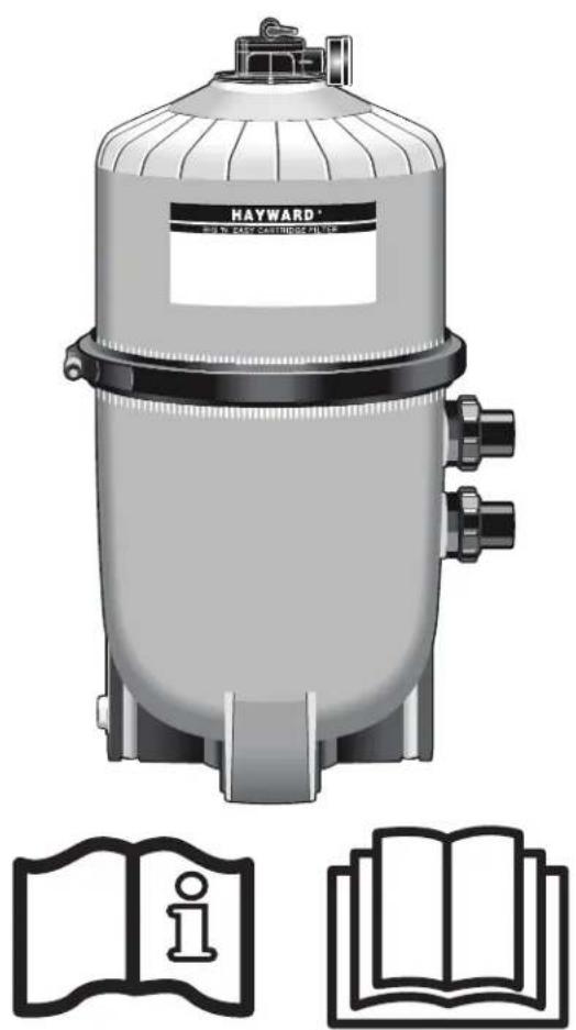
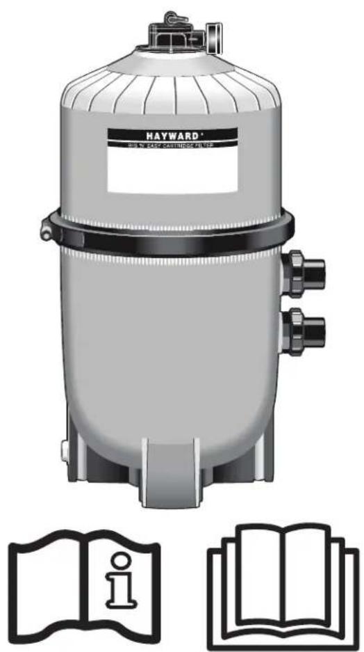
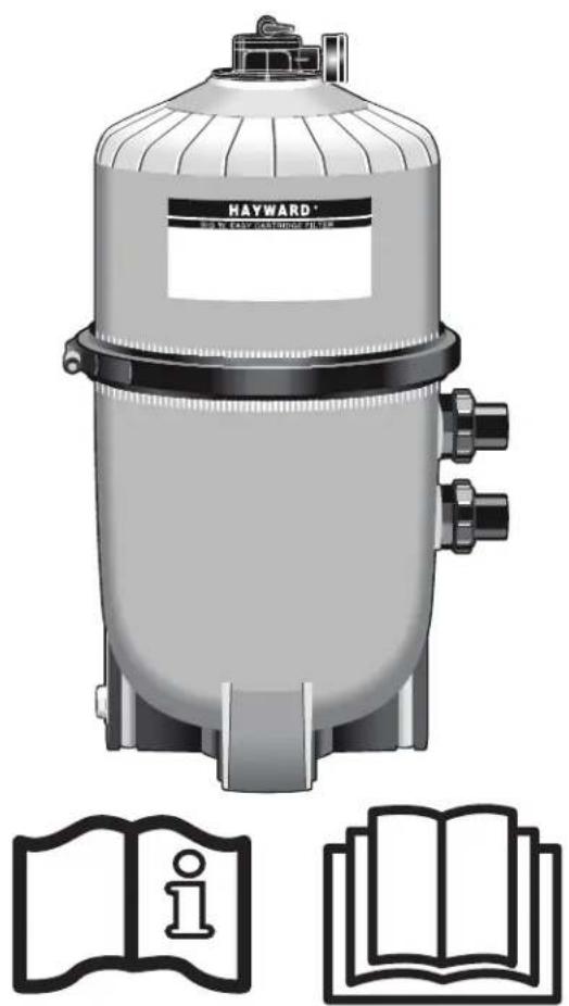
Illustration of a Hayward® water heater with open book and information icon (no text or symbols on main body)SWIMCLEAR™ CARTRIDGE FILTERS
OWNER'S MANUAL
SAVE THIS OWNER'S MANUAL

WARNING - Read and follow all instructions in this owner's manual and on the equipment. Failure to follow instructions can cause injury.
WARNING – This document should be given to the owner of the swimming pool and must be kept by the owner in a safe place.
WARNING – This appliance is not intended for use by persons (including children) with reduced physical, sensory or mental capabilities, or lack of experience and knowledge, unless they have been given supervision or instruction concerning use of the appliance by a person responsible for their safety.
WARNING – To reduce risk of injury, do not permit children to use or climb on this product. Closely supervise children at all times.
WARNING – Pool and spa water circulation systems operate under hazardous pressure during start up, normal operation, and possibly after pump shut off. Pressure in system can cause explosive component separation of the upper filter body if safety and operation instructions are not followed. Severe personal injury or death can result.
WARNING – This product should be installed and serviced only by a qualified pool professional.
TO AVOID COMPONENT SEPARATION
- Follow all safety and operation instructions.
- Do not operate water circulation system if a system component is assembled improperly, damaged, missing, or not a genuine Hayward component.
- Before performing maintenance on the water circulation system, verify all system and pump controls are in OFF position and filter manual air relief valve is in the OPEN position.
- Use ONLY Hayward clamp system components: DEX2421JKIT clamp assembly, DEX2421J2 nut/ bolt assembly, and a DEX2422Z2 metal reinforced seal. Non-Hayward components may fail in use and cause explosive separation.
- Never rely on hand tightening the clamp nut to the clamp bolt. Using a 34 inch socket on a torque wrench, torque clamp nut and clamp bolt to 17 Nm (150 inch-lbs).
- Before starting system pump, insure filter manual air relief valve body is in LOCK position in filter upper body.
- Before starting the system pump, verify that all system valves are set in a position to allow water from the filter to return back to the pool.
- Before starting the system pump, the manual air relief valve must be in the OPEN position.
- When starting pump, do not stand over or near filter.
- If water leakage appears in the area of the filter tank clamp, immediately turn off all system circulation pumps and electrical power. Do not return to the filter until all water flow has stopped. Reassemble the clamp system per the instructions in this owner's manual to stop the leak.
- Return to filter to close manual air relief valve only when a steady stream of water (Not air or air and water mix) is discharged from the manual air relief valve.
- Do not change filter control valve position while system pump is running.
WARNING – Pressure testing of the pump and filter system in excess of the 3,5 Bar (50 PSI) can cause explosive separation of the components. Component separation can result in severe personal injury or death.
USE ONLY HAYWARD GENUINE REPLACEMENT PARTS
REGISTRATION
Thank you for choosing Hayward. This manual contains important information regarding the operation and maintenance of your product. Please retain it for reference.
TO REGISTER YOUR PRODUCT IN OUR DATABASE, GO TO:
www.hayward.fr/en/services/register-your-product

For Your Records
Record the following information for your convenience:
1) Purchase Date
2) Complete Name ____
3) Address
4) Zip code
5) Email Address
6) Part number Serial number
7) Pool Dealer
8) Address
9) Zip code ____ Country ____
Note

GENERAL INFORMATION
Your Hayward SwimClear™ cartridge filter combines superior water filtration with ease of operation and totally corrosion-resistant construction. They are designed for continuous or intermittent operation, for installation above or below the pool water line, for fresh or salt water swimming pools or spas. SwimClear™ filters utilize multiple reusable, reinforced polyester filter cartridge elements to provide a high degree of water clarity and long filter cycles with minimum care.
INSTALLATION

WARNING – This product should be installed and serviced only by a qualified pool professional.
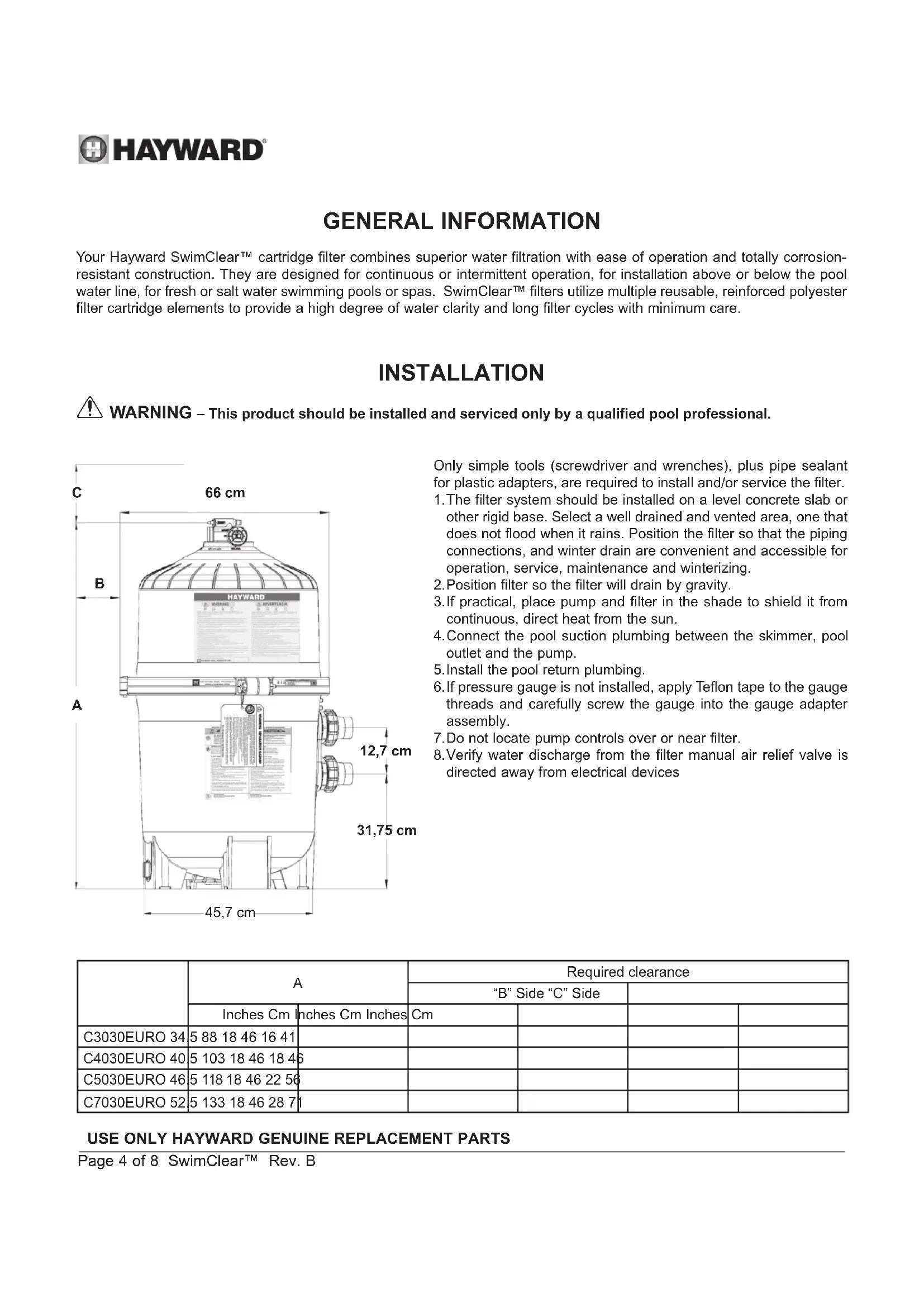
text_image
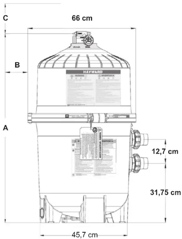
C 66 cm B HAYWARD WARNING APERTICUM 12,7 cm 31,75 cm A 45,7 cmOnly simple tools (screwdriver and wrenches), plus pipe sealant for plastic adapters, are required to install and/or service the filter.
-
The filter system should be installed on a level concrete slab or other rigid base. Select a well drained and vented area, one that does not flood when it rains. Position the filter so that the piping connections, and winter drain are convenient and accessible for operation, service, maintenance and winterizing.
-
Position filter so the filter will drain by gravity.
-
If practical, place pump and filter in the shade to shield it from continuous, direct heat from the sun.
-
Connect the pool suction plumbing between the skimmer, pool outlet and the pump.
-
Install the pool return plumbing.
-
If pressure gauge is not installed, apply Teflon tape to the gauge threads and carefully screw the gauge into the gauge adapter assembly.
-
Do not locate pump controls over or near filter.
-
Verify water discharge from the filter manual air relief valve is directed away from electrical devices
| A | Required clearance | |||||
| “B” Side “C” Side | ||||||
| Inches Cm | Inches Cm Inches | Cm | ||||
| C3030EURO 34 | 5 88 18 46 16 41 | |||||
| C4030EURO 40 | 5 103 18 46 18 46 | |||||
| C5030EURO 46 | 5 118 18 46 22 56 | |||||
| C7030EURO 52 | 5 133 18 46 28 71 | |||||
USE ONLY HAYWARD GENUINE REPLACEMENT PARTS
STARTING UP
Before Starting the Pump
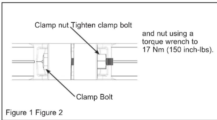
- Use ONLY Hayward clamp system components; DEX2421JKIT clamp system, DEX2421J2 nut/bolt assembly, DEX2422Z2 metal reinforced seal. Non-Hayward clamp components may fail in use and cause explosive component separation. Verify that upper and lower filter bodies are properly secured with the filter body clamp. Never rely on hand tightening the clamp nut to the clamp bolt. Using a 34 inch socket on a torque wrench, torque clamp nut to clamp bolt to 17 Nm (150 inch-lbs). Verify that the filter manual air relief body is in the LOCK position, and no filter components are missing, damaged or not genuine Hayward components. (See Fig 2)
- Close filter drain. Note: Filter plug requires an o-ring seal. (See Fig 4)
- Open all system valves to allow water from the pool to the filtration system and from the filter to return to the pool.
- Place the manual air relief valve in OPEN position. (See Fig 2)
Starting Pump
- When starting system pump, do not stand over or near filter. If water leakage appears at filter tank clamp, immediately turn off all system circulation pumps and all electrical power. Do not return to the filter until all water leakage has stopped. Reassemble the clamp system per the instructions on page 7 in this owner's manual to stop leak.
- Return to filter to CLOSE manual air relief valve only when a steady stream of water (not air or, air and water mix) is discharged from the manual air relief valve.
text_image
Clamp nut Tighten clamp bolt and nut using a torque wrench to 17 Nm (150 inch-lbs). Clamp Bolt Figure 1 Figure 2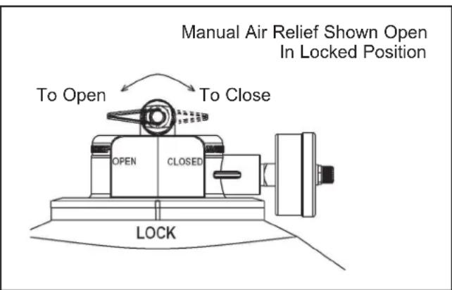
text_image
Manual Air Relief Shown Open In Locked Position To Open To Close OPEN CLOSED LOCKOPERATION
FILTERING
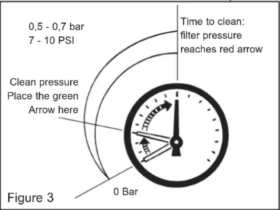
Filtration starts as soon as flow is steady through the filter. As the filter removes dirt from the pool water, the accumulated dirt causes a resistance to flow. As a result, the gauge pressure will rise and the flow will decrease. When the pressure
rises between 0.5 and 0.7 bar (7 - 10 psi) above the starting pressure, or when the flow decreases below the desired rate, clean or replace the filter cartridge elements. Once your filter is running and there is a pressure reading, line up the green arrow with the current reading. (See Fig 3) When the pressure rises to or above the red or second arrow, it is time to clean or replace your filter cartridge elements.
By recording the initial starting pressure (with clean filter elements) a determination can be made when the filter cartridge elements should be replaced rather than cleaned. After the filter elements have been cleaned and reinstalled if the starting pressure is higher than 0.4 Bar (6 PSI) above the starting pressure with the new filter cartridge elements, the filter cartridge elements should be replaced the next time the gauge arrow reaches the red arrow.
text_image
0,5 - 0,7 bar 7 - 10 PSI Time to clean: filter pressure reaches red arrow Clean pressure Place the green Arrow here 0 Bar Figure 3USE ONLY HAYWARD GENUINE REPLACEMENT PARTS
MAINTENANCE

WARNING – This product should be installed and serviced only by a qualified pool professional.
FILTER DISASSEMBLY INSTRUCTIONS
- Turn off all system circulation pumps and all electric power on the pad.
- Set all system valves in a position to prevent water flow to the filter.
- The manual air relief valve must be placed in the OPEN position. (FIG 2)
- Remove filter drain plug (FIG 4) and drain water from filter.
- Using 34 inch wrenches, loosen and remove the clamp nut and the clamp bolt.
- Holding both ends of the filter body clamp carefully spread the clamp ends. Remove the clamp by lifting over the upper filter body. Do not drop the clamp during removal because the clamp could be damaged. Do not strike the clamp with metal tools as they can damage the clamp.
- Lift off upper filter body. Do not use the pressure gauge to lift the upper filter body.
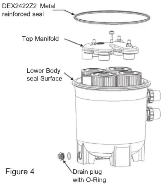
text_image
DEX2422Z2 Metal reinforced seal Top Manifold Lower Body seal Surface Figure 4 Drain plug with O-RingREMOVING CARTRIDGES
- Remove the top Manifold, which is exposed when the upper filter body is removed. (Fig 4)
- Remove the filter cartridge elements by using slight rocking motion and lifting up.
- Clean filter cartridge elements.
CLEANING CARTRIDGES
The Cartridge filter element can be cleaned by washing inside and outside with a garden hose. After hosing cartridge, for best results, carefully brush the pleated surface to remove fine particles. Do not pressure wash as it can damage the filter element.
You may find some debris on the cartridge pleats, which may not have been removed with hosing.
CLEANING CARTRIDGES
- Flush and drain any dirt or debris from the bottom of the lower filter body.
- Flush any dirt or debris from the upper filter body and from around the manual air relief area.
- Carefully replace the cartridges over the hubs on the bottom seal plate.
- Place top manifold securely on top of cartridges, aligning the return pipe with the port in the manifold
CLEAN SEAL RING AND SEAL SURFACE
- Remove filter tank seal.
- With a clean cloth wipe the lower filter body seal surface. (Fig 4) Do not use a solvent.
- With a clean cloth wipe the upper filter body seal surface.

Notice: Do not use any petroleum solvents to clean filter components. Do not lubricate DEX2422Z2 Seal.
USE ONLY HAYWARD GENUINE REPLACEMENT PARTS
BODY AND CLAMP RE-ASSEMBLY
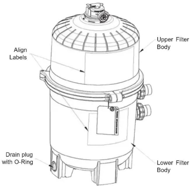
- Place the metal reinforced seal on the lower filter body (Fig 4). Place the upper filter body on the Hayward DEX2422Z2 metal reinforced seal and lower filter body in a position which allows all operation and safety labels to be clearly visible and the upper body to be centered on the lower filter body. Press down firmly and evenly to set the upper filter body. (Fig 5)
- Replace the filter clamp around the upper and lower filter bodies. Hold the clamp ends to position the clamp on the filter bodies with the clamp ends adjacent to the safety and operation labels on the filter bodies. (Fig 5)

WARNING – DO NOT HIT OR STRIKE CLAMP WITH HAMMER OR METAL TOOLS.
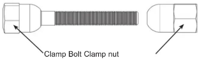
- Insert clamp bolt through the clamp ends and thread the clamp nut onto clamp bolt with rounded end of the nut (Fig 6) towards the ends of the clamp.
- Never rely on hand tightening of clamp nut to clamp bolt. Using a 34 inch socket on a torque wrench, torque clamp nut to clamp bolt to 17 Nm (150 inch-lbs). (Fig 1).
- Follow Operation Instructions for "Starting the Pump and Filter System"
VACUUMING POOL
Vacuuming can be performed directly into the filter whenever needed. Backwash filter after vacuuming, if required.
text_image
Align Labels Upper Filter Body Drain plug with O-Ring Lower Filter BodyFigure 5
text_image
Clamp Bolt Clamp nutFigure 6
REMOVING THE MANUAL AIR RELIEF VALVE
Your Filter comes with a Manual Air Relief Valve (MAR) pre-installed from the factory.
For Qualified pool professionals only: If MAR valve needs to be serviced, follow these instructions carefully.
- Turn off all system circulation pumps and all electric power on the pad.
- Set all system valves in a position to prevent water from flowing to the filter.
- The manual air relief valve must be placed in the OPEN position.
- Wait until all water leakage has stopped.
- Grasp the MAR body at the flats, turn the MAR counterclockwise until the indicator on the MAR flange is aligned with the "UNLOCK" position on the upper filter body.
- Pull straight up to remove the MAR, a slight rocking motion may help.
RE-INSTALLATION OF THE MANUAL AIR RELIEF VALVE
In areas where subfreezing temperatures can be expected, the filter should be drained to protect the filter from damage.
- The filter should be disassembled and the filter elements cleaned or replaced.
- Follow directions under FILTER DISASSEMBLY INSTRUCTIONS
- Then REMOVING CARTRIDGES and CLEANING CARTRIDGES per instructions
- Reassemble per the instructions.
- Be sure to leave the drain plug unattached during the winter season to avoid cracking the filter body.
USE ONLY HAYWARD GENUINE REPLACEMENT PARTS
WINTERIZING FILTER
In areas where subfreezing temperatures can be expected, the filter should be drained to protect the filter from damage.
- The filter should be disassembled and the filter cartridges elements cleaned or replaced.
- Follow directions under FILTER DISASSEMBLY INSTRUCTIONS
- Then follow REMOVING CARTRIDGES per instructions
- Reassemble per FILTER RE-ASSEMBLY INSTRUCTIONS.
- Be sure to leave the drain plug unattached during the winter season to avoid cracking the filter body.
SERVICE AND REPAIRS
Consult your local authorized Hayward dealer or service center. No returns may be made directly to the factory without the expressed written authorization of Hayward Pool Europe.
CHEMICAL IDEAL LEVELS
| Combined chlorine 0.2 | bpm Maximum |
| Chlorine (Stabilized) 1.0 | to 3.0 ppm |
| pH 7.2 to 7.6 | |
| Cyanuric Acid (Stabilizer) | 20 to 30 ppm |
| Total Alkalinity 80 to 120 | ppm |
| Calcium Hardness 200 | to 300 ppm |
PROBLEM SOLVING LIST
| Remedy Low water flow Short filter cycles | Pool water won’t clear up | |
| 1. Check skimmer and pump strainer baskets for debris.2. Check for restrictions in intake and discharge lines3. Check for air leak in intake line (indicated by bubbles returning to pool). | 1. Check for algae in pool and super-chlorinate as required.2. Be sure chlorine and pH levels are in proper range (adjust as required).3. Operate filter for longer periods. | |
CHARACTERISTICS
| Model | Effective filtration rate | Design flow rate | ||
| Ft^2 | M^2 | GPM | M^3/h | |
| C3030EURO | 325 | 30.2 | 60 | 14 |
| C4030EURO | 425 | 39.5 | 100 | 22 |
| C5030EURO | 525 | 48.8 | 130 | 30 |
| C7030EURO | 680 | 63.2 | 155 | 35 |
| Maximum working pressure for all models 3.5 Bar (50 PSI) | ||||

natural_image
Abstract geometric logo with stylized letter H inside a circular frame (no text or symbols)HAYWARD®

natural_image
Illustration of a Hayward® water heater with open book and information icon (no text or symbols on main body)SWIMCLEAR™ FILTROS DE CARTUCHO
MANUAL DEL USUARIO
CONSERVE ESTE MANUAL DE INSTRUCCIONES

natural_image
Abstract geometric logo with stylized letter H inside a circular frame (no text or symbols)HAYWARD®

natural_image
Illustration of a Hayward® water heater with open book and information icon (no text or symbols on main body)SWIMCLEAR™ FILTROS DE CARTUCHO
MANUAL DO UTILIZADOR
GUARDE ESTE MANUAL DE INSTRUCCÕES

www.hayward.fr/en/services/register-your-product

Para seu registo
natural_image
Abstract geometric logo with stylized letter H inside a circular frame (no text or symbols)HAYWARD®

natural_image
Illustration of a Hayward® water heater with open book and information icon (no text or symbols on main body)www.hayward.fr/en/services/register-your-product

Für Ihre Unterlagen
ABSAUGEN DES SCHWIMMBECKENS
natural_image
Technical line drawing of a bolt and nut assembly (no text or symbols)natural_image
Abstract geometric logo with stylized letter H inside a circular frame (no text or symbols)HAYWARD®
natural_image
Illustration of a Hayward® water heater with open book and information icon (no text or symbols on main body)SWIMCLEAR™ CARTRIDGE FILTERS
GEBRUIKERSHANDBOEK
BEWAAR DEZE HANDLEIDING

www.hayward.fr/en/services/register-your-product

text_image
Klembout KlemmoerFiguur 6
VERWIJDEREN VAN DE MANUELE ONTLUCHTINGSKLEP
LIJST PROBLEEMOPLOSSING
natural_image
Abstract geometric logo with stylized letter H inside a circular frame (no text or symbols)HAYWARD®

natural_image
Illustration of a Hayward® water heater with open book and information icon (no text or symbols on main body)SWIMCLEAR™ FILTRI A CARTUCCIA
MANUALE PER L'USO
CONSERVARE ACCURATAMENTE IL PRESENTE MANUALE D'USO

www.hayward.fr/en/services/register-your-product

Dati da conservare
natural_image
Abstract geometric logo with stylized letter H inside a circular frame (no text or symbols)HAYWARD®

natural_image
Illustration of a Hayward® water heater with open book and information icon (no text or symbols on main body)SWIMCLEAR™ ПАТРОННЫЕ ФИЛЬТРЫ
www.hayward.fr/en/services/register-your-product

Для записей
All HAYWARD products are covered for manufacturing defects or material defects for a warranty period of 2 years as of date of purchases. Any warranty claim should be accompanied by evidence of purchase, indicating date of purchase. We would therefore advise you to keep your invoice.
The HAYWARD warranty is limited to repair or replacement, as chosen by HAYWARD, of the faulty products, provided that they have been subjected to normal use, in compliance with the guidelines given in their user guides, provided that the products have not been altered in any way, and provided that they have been used exclusively with HAYWARD parts and components. The warranty does not cover damage due to frost and to chemicals. Any other costs (transport, labour, etc.) are excluded from the warranty.
HAYWARD may not be held liable for any direct or indirect damage resulting from incorrect installation, incorrect connection, or incorrect operation of a product.
In order to claim on a warranty and in order to request repair or replacement of an article, please ask your dealer.
No equipment returned to our factory will be accepted without our prior written approval.
Wearing parts are not covered by the warranty.
Product with warranty extension : Tank 10 years.