Booster - Pump HAYWARD - Free user manual and instructions
Find the device manual for free Booster HAYWARD in PDF.
Frequently Asked Questions - Booster HAYWARD
User questions about Booster HAYWARD
0 question about this device. Answer the ones you know or ask your own.
Ask a new question about this device
Download the instructions for your Pump in PDF format for free! Find your manual Booster - HAYWARD and take your electronic device back in hand. On this page are published all the documents necessary for the use of your device. Booster by HAYWARD.
USER MANUAL Booster HAYWARD
SAVE THIS OWNER'S MANUAL
WARNING - Disconnect the pump from the main power supply completely before servicing the pump or filter.
WARNING - FOR PROFESSIONAL USE - All electrical connections must be done by a qualified electrician according to local electrical standard or, failing that, to the International Standard IEC 60364-7-702.
WARNING - Be certain the machine is only plugged into a protected 230V outlet that is protected from short-circuits. The pump is to be supplied by an isolating transformer or supplied through a residual current device (RCD) having a rated residual operating current not exceeding 30 mA.
WARNING - Children should be supervised to ensure that they do not play with the appliance. Keep fingers and foreign objects away from openings and moving parts.
WARNING - Motor must be suitably grounded. Connect ground wire to green grounding screw and for cord connected units use properly grounded outlet.
WARNING - Use a motor bonding lug to connect motor with other bonded parts using the appropriate size conductor as required by electrical codes.
WARNING - When making these electrical connections, refer to the diagram given under the lid of the motor terminal box. Be sure to check the electric connections are tight and sealed before powering up. Replace all covers before operation.
WARNING - Make sure that the power supply voltage required by the motor corresponds to that of the distribution network and that the power supply cables matches the power and current of the pump.
WARNING – Read and follow all instructions in this owner's manual and on the equipment. Failure to follow instructions can cause serious injury or death
This document should be given to the owner of the swimming pool and must be kept by the owner in a safe place.
WARNING – The appliance can be used by children aged from 8 years and above and persons with reduced physical, sensory or mental capabilities, or lack of experience and knowledge, if they have been given supervision or instruction concerning use of the appliance in a safe way and understand the hazards involved.
WARNING - Cleaning and user maintenance shall not be made by children without supervision.
WARNING - The pump is intended for continuous operation at Maximum Water temperature 35^ .
WARNING - Use Only Genuine Hayward® Replacement Parts.
WARNING - If the supply cord is damaged it must be replaced by the manufacturer, service agent, or similarly qualified persons in order to avoid a hazard.
WARNING - For disconnection from main power supply an external switch having a contact separation in all poles that provide a full disconnection under overvoltage category III conditions must be incorporated in the fixed wiring in accordance with the wiring rules.
WARNING - Do not operate the swimming pool pump if the power cord or the housing of the motor connection box is damaged. This can cause an electric shock. A damaged power cord or motor connection box must be replaced by a service agent or a similarly qualified person immediately in order to avoid a hazard.
WARNING – This pool motor is NOT equipped with a Safety Vacuum Release System (SVRS). SVRS helps prevent drowning due to body entrapment on underwater drains. In some pool configuration, if a person's body covers the drain, the person can be trapped by suction. Depending on your pool configuration, a SVRS may be required to meet local requirements.
GENERAL
Install the pump at the right distance from the base in to minimize the distance between the suction point and the pump so as to avoid pointless and excessive load losses in the hydraulic circuit.
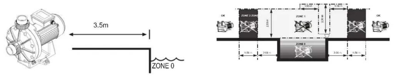
However, it is mandatory to allow a safety distance (3.5 m minimum) as required by the current installation standard. Install and use the product at an altitude less than 2000 m.
Install the pump in a ventilated and dry place. The motor requires air to flow freely around it to provide for natural ventilation. The pump has to be installed, so that the plug and the wall socket outlet is easily visible and accessible. The pump has to be installed, so that the external disconnect switch which is incorporated in the fixed wiring is easily visible and accessible. The switch has to be located close to the pump.
The pump must be permanently mounted to a concrete base using lag screws suitable for concrete where pilot holes have been drilled. Locking washers must be supplied to prevent loosening of the mounting lag screws over time. If the pump is to be mounted to a wooden deck then lag screws suitable for wood must be used - with lock washers to prevent loosening over time.
The acoustic level of the Hayward® pumps is lower than 70 dBA.
Necessary arrangements :
- Connect the pump to ground
- Connect the pump with a H07RN-F 3G1,5mm² type cable.
- Fit a 30mA residual current (RCD) device to protect people from electric shock caused by a possible break in the electrical insulation.
- Provide protection against short-circuiting (the definition of the rating will depend on the value indicated on the motor name plate).
- Provide a circuit separation device with a 3mm opening on all the poles.
The single phase motors fitted to our pumps are provided with thermal protection. This protection operates on an overload or in the event of abnormal heating of the motor coil and is reset automatically when the winding temperature drops.
If so required by regulations and whatever the motor type, in addition to the devices mentioned above, it is also necessary to install a thermomagnetic protective device calibrated in accordance with the indications on the motor name-plate.
The table on page 51 indicates the various characteristics of the motors fitted to our pumps.
ELECTRICAL CONNECTION: Make sure that the power supply voltage required by the motor corresponds to that of the distribution network and that the power supply cables matches the power and current of the pump.
All the electric connections of the pump and the possible change of power supply cable must be done by a qualified professional so as to avoid all possible danger.
When making these electrical connections, refer to the diagram given under the lid of the motor terminal box.
Be sure to check the electric connections are tight and sealed before powering up. Replace all covers before operation. The pre-wiring (test leads) that might be included on some of the pumps must be removed for final connection of the pump to the electric power supply. This pre-equipment (test leads) is only used for works testing during the manufacturing phases.
INSTALLATION INSTRUCTIONS
Install the pump so as to reduce pressure drops to a minimum whilst complying with the distances specified in the installation standard, namely 3.5m minimum between the pump and the pool. The suction pipe must be installed with a slight uphill incline towards the pump axis. Ensure that the connections are correctly tightened and watertight. However, avoid excessively tightening the pipes. For plastic materials, use Teflon only to ensure watertightness. The diameter of the suction pipe shall depend on that of the discharge pipe. Avoid damp or non-ventilated locations. The motor requires the cooling air to circulate freely.
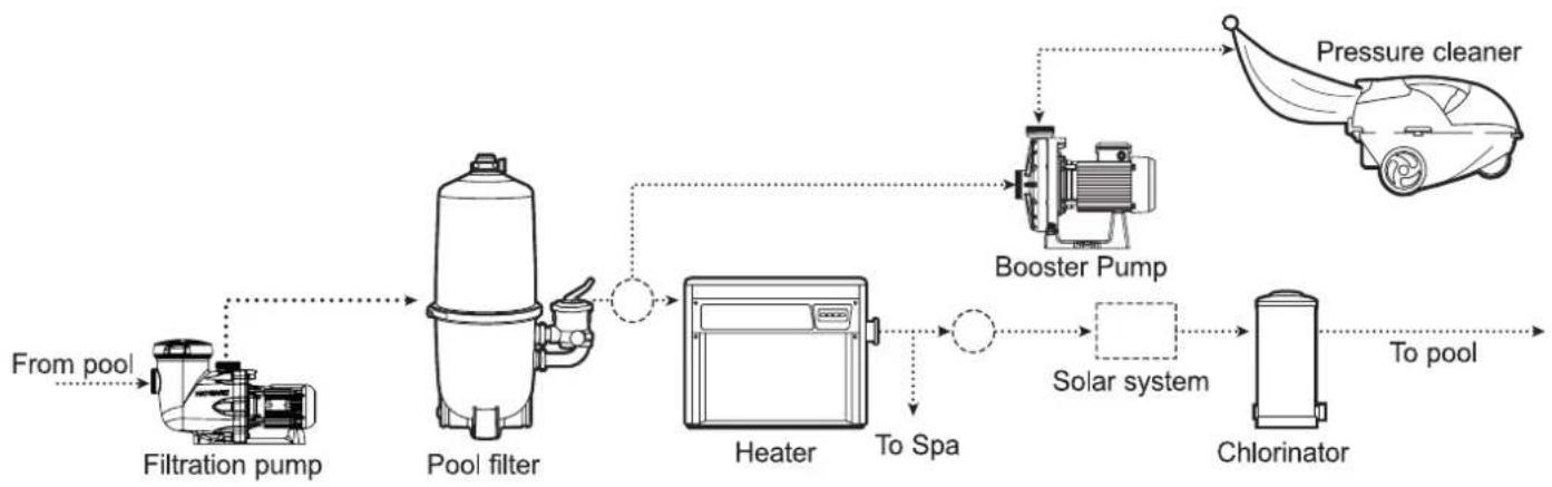
It is recommended to use the supplied union fittings with 50~mm pipe for best performance. The filtration system must supply a minimum of 2m3 / h of water to the booster pump. Do not connect the booster pump inlet plumbing into the top of a horizontal pipe. If the booster pump is installed below the water level of the pool, a gate valve must be installed between the booster pump and the filtration system. The gate valve is a means to close off the water supply to the booster pump should it require maintenance. Fittings restrict flow. For better efficiency, use the fewest possible fittings (but at least two suction outlets). Avoid fittings that could cause an air trap.
Pipe Sizing Chart :
| Maximum Recommended Flow Per Hose Size (Suction) | ||||||||
| Pipe diameter (mm) | Flow (m3/h) | Suction hose length* (mm) | Pipe diameter (mm) | Flow (m3/h) | Suction hose length* (mm) | Pipe diameter (mm) | Flow (m3/h) | Suction hose length* (mm) |
| 32 4,5 1 | 0 50 10,2 250 | 75 24,9 375 | ||||||
| 40 6,6 2 | 0 63 18 315 9 | 0 36 450 | ||||||
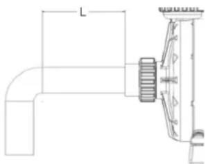
- NOTE - It is recommended that a minimum length of straight piping (shown as "L" in diagram at left), equivalent to 5 pipe size diameters, be used between the pump suction inlet and any plumbing fittings (elbows, valves, etc.).
Time Clock :
CAUTION - Risk of equipment damage. Never run the booster pump without the filtration system operating. Running the booster pump dry will damage the pump and void its warranty.
Installation of a separate time clock for the booster pump is recommended. Set timers so that the cleaner turns on at least one half hour after the filtration system starts, and turns off at least one half hour before the filtration system turns off. Time clocks for the filtration system and the booster pump must be coordinated at all times to insure proper sequence of the filtration system and cleaner operations. If the power to the time clocks is shut off or interrupted for any reason, the time clocks must be reset. A longer than normal cleaning cycle is recommended for the first 30 days of operation. If an automatic control system is used, please refer to the manufacturer's installation guide.
Starting the Pump:
The filtration system pump must be running, and an automatic pool cleaner must be connected before starting the booster pump. If water leakage occurs from anywhere on the pump or filter, immediately turn off all system circulation pumps and all electrical power before repairing the leak. Do not return to the pump or filter until all water flow has stopped. If no leakage occurs, stand at least 10 feet from pump and/or filter and proceed with starting the pump.
WARNING - Return to filter to close filter manual air relief valve when a steady stream of water (not air or air and water mix) is discharged from valve. Failure to do so could result in severe personal injury.
CAUTION - RISK OF EQUIPMENT DAMAGE. Never operate the booster pump without water. Water acts as a coolant and lubricant for the mechanical shaft seal. NEVER run pump dry. Running pump dry may damage seals, causing leakage, flooding, and voids warranty. The filtration system pump must be running before the booster pump is started. It is extremely important for the booster pump to have an adequate water supply from the filtration system at all times. The booster pump is not self-priming. To ensure that there is an adequate water supply for the booster pump:
open any valves at the inlet and outlet of the booster pump before operation.
- set all filtration system valves in a manner that does not deprive the booster pump of water during operation.
do not operate the booster pump without a pressure cleaner connected to the system.
- set time clocks such that the booster pump only operates when the filtration system is on.
- clean filtration system regularly to prevent flow restrictions.
CAUTION - RISK OF EQUIPMENT DAMAGE. Do NOT add chemicals to pool/spa system directly in front of pump suction. Adding undiluted chemicals may damage pump and voids warranty.
If filtration system pump is to be turned off for any reason, then the booster pump must be turned off before turning off the filtration system pump.
NOTE - If the Hayward® booster pump is used to replace the booster pump in an existing pressure cleaner installation, then the cleaner operating pressure should be reset according to the cleaner manufacturer's recommended procedure.
MAINTENANCE
- Hayward® pumps have self-lubricating motor bearings and shaft seals. No lubrication is necessary
- Keep motor clean. Insure air vents are free from obstruction.
- Occasionally, mechanical seals become damaged or worn and must be replaced.
- Except for cleaning activities, any repairing, servicing and maintenance has to be performed by a Hayward authorized service agent or a similarly qualified person.
Wear parts of the pump mentioned below should be maintained according to their estimated life:
Wear
parts
Mechanical seal
2 years or 10.000 hours.
Motor bearings kit
2 years or 10.000 hours.
Set of gasket (strainer, housing, bulkheads, drain)
Capacitor
Estimated
life
2 years or 25.000 hours.
2 years or 10.000 hours.
WINTERIZING/STORAGE
- Drain pump by removing drain plug(s).
- Disconnect electrical wires and pipe connections, and store pump in a dry, well-ventilated room. Or, as a minimum precaution: Disconnect electrical wires. Remove 8 bolts holding bracket and motor assembly to Strainer/Housing and store assembly in a dry, well-ventilated room. Protect remaining Housing assembly from the elements by covering.
NOTE: Before Re-Activating pump, thoroughly clean and remove scale, dirt, etc.
TROUBLE SHOOTING GUIDE
A) Motor won't start
- Check for improper or loose connections, open switches or relays, blown circuit breakers or fuses.
- Manually check rotation of motor shaft for free movement and lack of obstruction.
B) Motor cuts out - Check for :
- Wiring, loose connections, etc.
- Low voltage at motor (frequently caused by undersized wiring).
- Binding and overload. (Amperage reading.).
NOTE: Your pump motor is equipped with Automatic Thermal Overload Protection. The motor will automatically shut-off, under conditions before heat damage build-up, due to an improper operating condition, can occur. The motor will auto_restart when safe heat level is reached.
C) Motor hums, but does not start - Check for :
1 Open capacitor.
D) Noisy pump - Check for
- Air leak in suction causing rumbling in pump.
- Cavitation due to restricted or undersized suction line and unrestricted discharge lines. Correct suction condition or throttle discharge lines, if practical.
- Vibration due to improper mounting, etc.
- Foreign matter in pump housing.
- Motor bearings made unserviceable by wear, rust, or continual overheating.
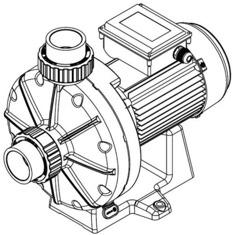

BOOSTER PUMP
MANUAL DEL USUARIO
- He noBpeKJdeH JIN KOHJeHcaTop;
D) Hacoc co3daet wym - npoBepbTe:
- YTO Ha yUacTke BCacbIBaHnH HeT NoCTyIeHn BO3dyXa, Co3daIOuTeo pOKoyuIry B HacoCe;
- YTO OTCYCTBYET KABNTaIyra, Bb3BaHHaN HeIOCTaTOHbIMn pa3Mepam Tpy60npoBOda BCacBHaHna NIIOrpaHnueHHeM Notoka, ININ N3bItoHbIMn pa3Mepam HArHeTaTeNbHorO Tpy60npoBOda.
IcnoIb3yIte BCaIbIaIOUe Tpy6oPBOOdbI npAunIbHOrO pa3Mepa IIN yCTaHOBtE yCTpoIcTBo cyKeHHa Tpy6oPBOOdax HArHeTaHn, eCIn 3TO Heo6xOIMo.
- YTO OTCYCTBYOT Bn6paCm BBNuD HEnpaBnIbHoro MOHTaKa;
- YTO BHyTpN KOpNyCa HAcOca Het INHOpoDHBx TeJ;
- YTO IOUHINHNI 3JIeKToDnBraTeIa He CTaII HEnpuroIDbIMN K IcNoJb3OBAHIO BBUy N3HOCA, PxABuHbI INI INI DInTeHBO npeperpeBa.
GUIDE TECHNIQUE DE LA POMPE - TECHNICAL GUIDE FOR THE PUMP - GUIA TECNICA PARA LA BOMBA - MANUAL TECNICO DA BOMBA - TECHNISCHE ANLEITUNG FÜR DIE PUMPE - TECHNISCHE GIDS VOOR DE POMP - GUIDA TECNICA PER LA POMPA -TEXHUNCECKOE PYKOBODCTBO NO HACOCY
| Pompe | Référence moteur | P1 MAX Consommation maximale de la pompe | Voltage Fréquence Nb phase | Ampérage à P1 MAX | Condensateur | Calibre disjoncteurcourbe (D) | Hauteur mano-métrique àdébit nul |
| Pump | Reference motor | P1 MAX Maximum consumption of the pump | Voltage Frequency Nb phase | Amperage at P1 MAX | Capacitor | Circuit breaker gauge curve (D) | Table of 0 flow pressure heads |
| Bomba Referencia motor | P1 MAX Mâximo consumo de la bomba | Voltaje frequeência número de fases | Amperaje at P1 Max. | Condensador | Calibre de disyuntor curva (D) | Cuadro de las alturas mano-métricas con flujo 0 | |
| Bomba | Referência motor | P1 MAX Consumo máximo da bomba | Voltagem FreqüênciaNumero de fases | Amperagem em P1 MAX | Condensador | Calibre do disjunto curva (D) | Cuadro de alturas monométricas com caudal 0 |
| Pumpen Motor reference | P1 MAX Maximalverbrauch der Pumpe | Volt Frequenz Anzahl Phase | Stromstärke bei P1 MAX | Kondensator | Stroomonderbreker meter bocht (D) | Manometrische forderhöhe bei 0 leistung | |
| PompMotor referentie | P1 MAX Maximaal verbruik van de pomp | Spanning Frequentie Aantal fasen | Stroomsterkte bij P1 MAX | Condensator | Curvebrekermeter (D) | Tabel van mano-meterhoogten bij een debiet 0 | |
| Pompa | Tiferimento motore | P1 MAX Consumo massimo della pompa | Voltaggio Frequenza numero fasi | Amperaggio a P1 MAX | Condensatore | Calibro dell'interruttore curva (D) | Tabella delle alteze mano-metriche ad erogazione 0 |
| Hacoc | MOTOR cnparbki | P1 MAKC. Марсималький расхов на сosa | Напражениcope Тoka частota Homep усанtera | Сида тoka п ri P1 MAX | Кондематор | ДатукавTomатическая Выковочая Крвая (D) | давлие (падау = 0) |
| SP6050EE2 | SPX0750Z1CIE2 1190 W | 230 V~50 Hz 1 Phase | 5.2 A 35 μF | 450 V 6 D 26,3 M |
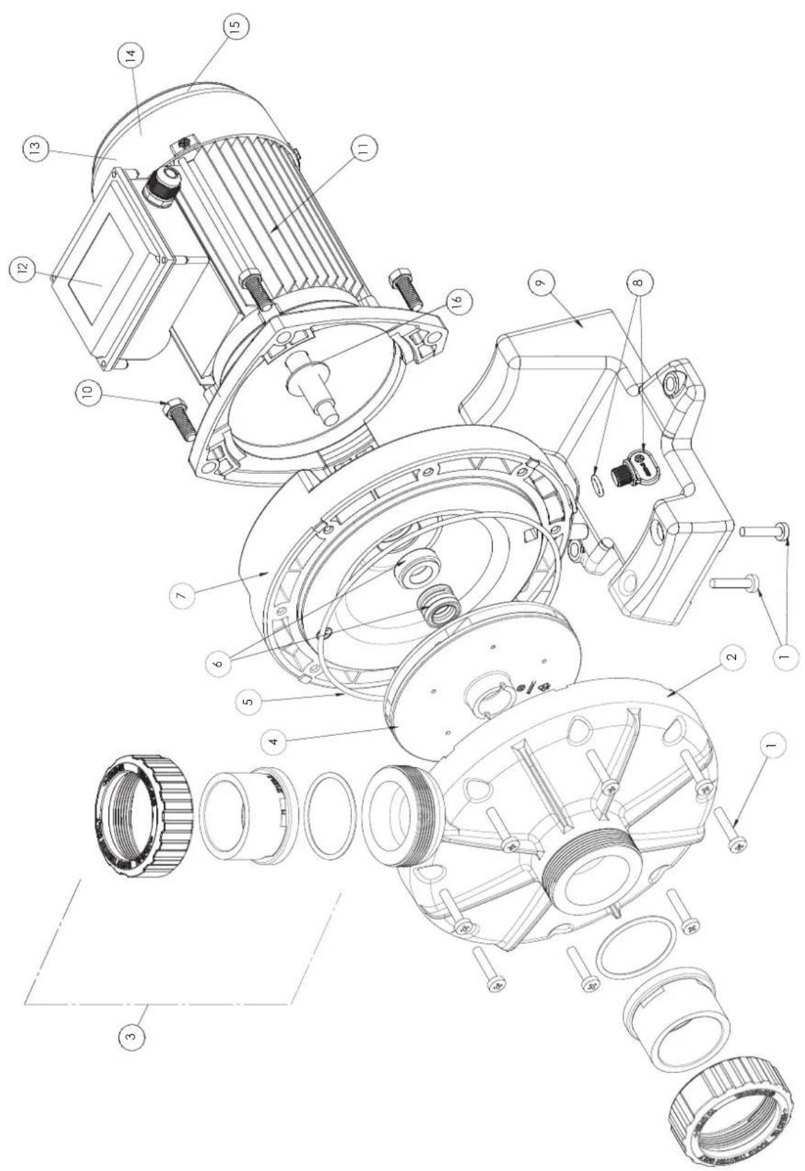
| N° | Description / Description / Bezeichnung / Descripción / Descrizione / Beschrljving / Descrição / O许可者 |
| 1 | Screw, 1/2" Type B x 1-1/4" • Vis pour corps de pompe • Schraube für Pumpegehäuse • Tornillo para cuerpo de bomba • Vite per corpo di pompa • Huisvestings GLB schroeven • Parafusos de tampão da carcaça • Komplèxt BWNTOB |
| 2 | Pump Volute • Couvercle de corps • Deckel Pumpengehäuse • Tapa • Coperchio • Zeef dekking • Tampa • Kpbütska hacoca |
| 3 | Union connector kit • Kit de raccord union 50mm • Anschluß-Stecker • Assemblaedel conectador de la unión • Assemblea del connettore del sindacato • de assemblage van de unieschakelaar • Conjunto do conector da unión • Φινηнг |
| 4 Impeller • Turbine • Laufrad • Turbina • Girante • Turbine • Turbina • Kpbütschatka | |
| 5 | Housing gasket • Joint de corps • Dichtung • Junta • Guarnizione corpo • Huisvestings pakking • Gaxeta da carcaça •УллOTNHITNELHoe кльцо |
| 6+7 | Seal plate +Shaft Seal assembly • Plateau d'étanchéité +Obturateur mécanique • Flansch + Motorhalterung • Plato de cierre + Cierre mecanico • Supporto di fissaggio + Tenuta meccanica • Verbindings plaat + Verbindings assemblage • Placa do selo + Conjunto de selo • Фланец + Салунik |
| 8 | Drain Plug • Bouchon de vidange • Ablasschaube • Tapón de vaciado • Tappo di spurgo • Afvoerkanaal stop • Plugue de dreno • Сливная побба |
| 9 | Motor support • Support de pompe • Socketteil • Soporte bomba • Supporto pompa • Opzettende steun • Suporte de montagem • Montaxhnaя с Todьka |
| 10 | Motor bolt • Vis moteur • Sechskrantschaube • Tornillo • Viti • Schroef motor • Tornillo a motor • Komplèxt BWNTOB |
| 11 Motor • Moteur • Motor • Motore • Motor • Motor • Θlektrodku ratelb | |
| 12 | Capacitor • Condensateur • Kondensator • Condensatore • Capacitor • Condensator • Kondehsatop |
| 13 Fan • Ventilateur • Fan • Ventilador • Fan • BENTILTATOP | |
| 14 Fan cover • Capot ventilateur • Lüfterhaube • Cubierta del ventilador • Copriventola • Fan cobertura • Ventilatordeksel • Koxyxb WEHTINPATOPA | |
| 15 Motor Bearings Kit • Kit Roulements moteur • Motorlager-Kit • Kit de rodamenti des motor • Kit cuscinetto del motore • Motorlagers kit • Kit rolamentos do motor • Пodiumпнки дviratetЯkomplèxt | |
| 16 Slinger • Larmier • Tropfing • Arandela Separación • Rondella di separazione • Tropfing • Arandela Separación • Macnocsbemhoe konbdo |
CONDITIONS DE GARANTIE ET EXCLUSIONS POUR LES PAYS DE L'UNION EUROPÉENNE
WARRANTY CONDITIONS AND EXCLUSIONS FOR EU COUNTRIES
Our consumer products in the European Union, which are intended to be sold to consumers and users, have a warranty in accordance with the relevant consumer protection regulations. All HAYWARD® products are covered for manufacturing defects or material defects for a warranty period of 3 years as of date of purchases. Any warranty claim should be accompanied by evidence of purchase, indicating date of purchase. We would therefore advise you to keep your invoice.
The HAYWARD® warranty is limited to repair or replacement, as chosen by HAYWARD®, of the faulty products, provided that they have been subjected to normal use, in compliance with the guidelines given in their user guides, provided that the products have not been altered in any way, and provided that they have been used exclusively with HAYWARD® parts and components. The warranty does not cover damage due to frost and to chemicals. Any other costs (transport, labour, etc.) are excluded from the warranty.
HAYWARD may not be held liable for any direct or indirect damage resulting from incorrect installation, incorrect connection, or incorrect operation of a product.
In order to claim on a warranty and in order to request repair or replacement of an article, please ask your dealer.
No equipment returned to our factory will be accepted without our prior written approval.
Wearing parts are not covered by the warranty (see maintenance part of the manual).
CONDICIONES DE GARANTIA Y EXCLUSIONES PARA PAÍSES DE LA UNión EUROPEA
Provision on waste electrical and electronic equipment from professionals. In accordance with Directive 2012/19/EU on the management of waste electrical and electronic equipment, this pump must be taken to a separate collection point. = = > Contact your distributor for more information