USER MANUAL Max Flo XL VS HAYWARD
natural_image
Abstract geometric logo with stylized letter H inside a circular frame (no text or symbols)
HAYWARD®
natural_image
Technical line drawing of a Hayward electric motor (no text or symbols on the diagram itself)

text_image
CE i
GUIDE DE L'UTILISATEUR
USER'S GUIDE
MANUAL DEL USUARIO
MANUAL DO UTILIZADOR
ANWENDER - HANDBUCH
GEBRUIKERSHANDBOEK
MANUALE PER L'USO
ANVÄNDARHANDLEDNING
BRUGERVEJELDNING
BRUKERVEILEDNING
KÄYTTÖOHJE
natural_image
Abstract geometric logo with stylized letter H inside a circular frame (no text or symbols)
HAYWARD®
natural_image
Technical line drawing of a Hayward electric motor (no text or symbols on the diagram itself)

text_image
CE i
POMPE CENTRIFUGE
À VITESSE VARIABLE
GUIDE DE L'UTILISATEUR
CONSERVEZ CE MANUEL POUR UNE CONSULTATION ULTÉRIEURE

natural_image
Abstract geometric logo with stylized letter 'H' inside a circular frame (no text or symbols)
HAYWARD®

natural_image
Technical line drawing of a Hayward electric motor (no text or symbols on the diagram itself)

text_image
CE i
VARIABLE SPEED CENTRIFUGAL PUMP
USER GUIDE
KEEP THIS MANUAL FOR FUTURE REFERENCE

⚠ WARNING - Read the instructions in this manual and on the appliance carefully. Failure to comply with the instructions may cause serious injury or death. This document must be given to all pool users who must keep it in a safe place.
⚠ WARNING – This appliance is not intended to be used by people (particularly children) with reduced physical, sensory or mental capabilities or by those lacking in experience or knowledge, unless they have been instructed in the use of the appliance or are under the supervision of a person responsible for their safety.
⚠ WARNING – Do not allow children to play with the appliance.
⚠ WARNING – Keep all foreign bodies, fingers and any other parts of the body away from openings and moving parts.
⚠ WARNING – Only use genuine Hayward spare parts.
⚠ WARNING – The installation of any electric swimming pool pump must be carried out in accordance with industry practices and with the standards currently applicable.
| F N F C 15-100 GB BS7671:1992 | | |
| D D IN VDE 0100-702 EW EVHS-HD 384-7-702 | | |
| A O VE 8001-4-702 | H M | SZ 2364-702:1994 / MSZ 10-533 1/1990 |
| E | UNE 20460-7-702 1993, REBT ITC-BT-31 2002 | M | MSA HD 384-7-702.S2 |
| IRL | IS HD 384-7-702 | PL | PN-IEC 60364-7-702:1999 |
| I | CEI 64-8/7 | CZ | CSN 33 2000 7-702 |
| LUX | 384-7.702 S2 | SK | STN 33 2000-7-702 |
| NL | NEN 1010-7-702 | SLO | SIST HD 384-7-702.S2 |
| P R SIUEE | TR T$ IEC 60364-7-702 |
⚠ WARNING – If the power cable is damaged, it must be replaced by the manufacturer, the manufacturer's after-sales service or persons with a similar qualification to avoid any danger.
⚠ WARNING – Ensure the pump is connected to a 230V socket√ with short circuit protection. The pump must also be powered via an isolation transformer or a residual current device (RCD) for which the residual rated operating current does not exceed 30mA.
⚠ WARNING – Completely disconnect the pump from the mains power supply before opening the cover and cleaning the strainer.
⚠ WARNING – To disconnect the pump from the mains power supply, an external switch with contact separation on all the poles ensuring complete disconnection in the event of category III overvoltage must be integrated into the fixed unit in accordance with the rules applicable to wiring.
⚠ WARNING – The pool pump must never be started if the power cord or the housing of the motor control unit are damaged, as there is a risk of electric shock. A damaged power cord or motor control unit must be replaced immediately by an approved technician or qualified person to prevent any risk.
⚠ WARNING – This motor is NOT fitted with an SVRS (Safety Vacuum Release System). The SVRS helps to prevent drowning if people find themselves trapped against the outlet pipe under the surface of the water. In some swimming pool configurations, if the body of a person blocks the outlet pipe, the person risks being trapped by the suction. Depending on the configuration of your pool, local regulations may require the installation of an SVRS.
REGISTRATION
Hayward thanks you for buying this product. This manual contains important information regarding the operation and maintenance of your product. Keep it carefully for future reference.
TO REGISTER YOUR PRODUCT, GO TO:
http://www.hayward.fr/en/services/register-your-product

Record the following information future reference, if necessary:
1) Date of purchase
2) Name
3) Address
4) Post Code
5) Email
6) Part number ____ Serial number ____
7) Dealer
8) Address
9) Post code ____ Country ____
Note

GENERAL POINTS
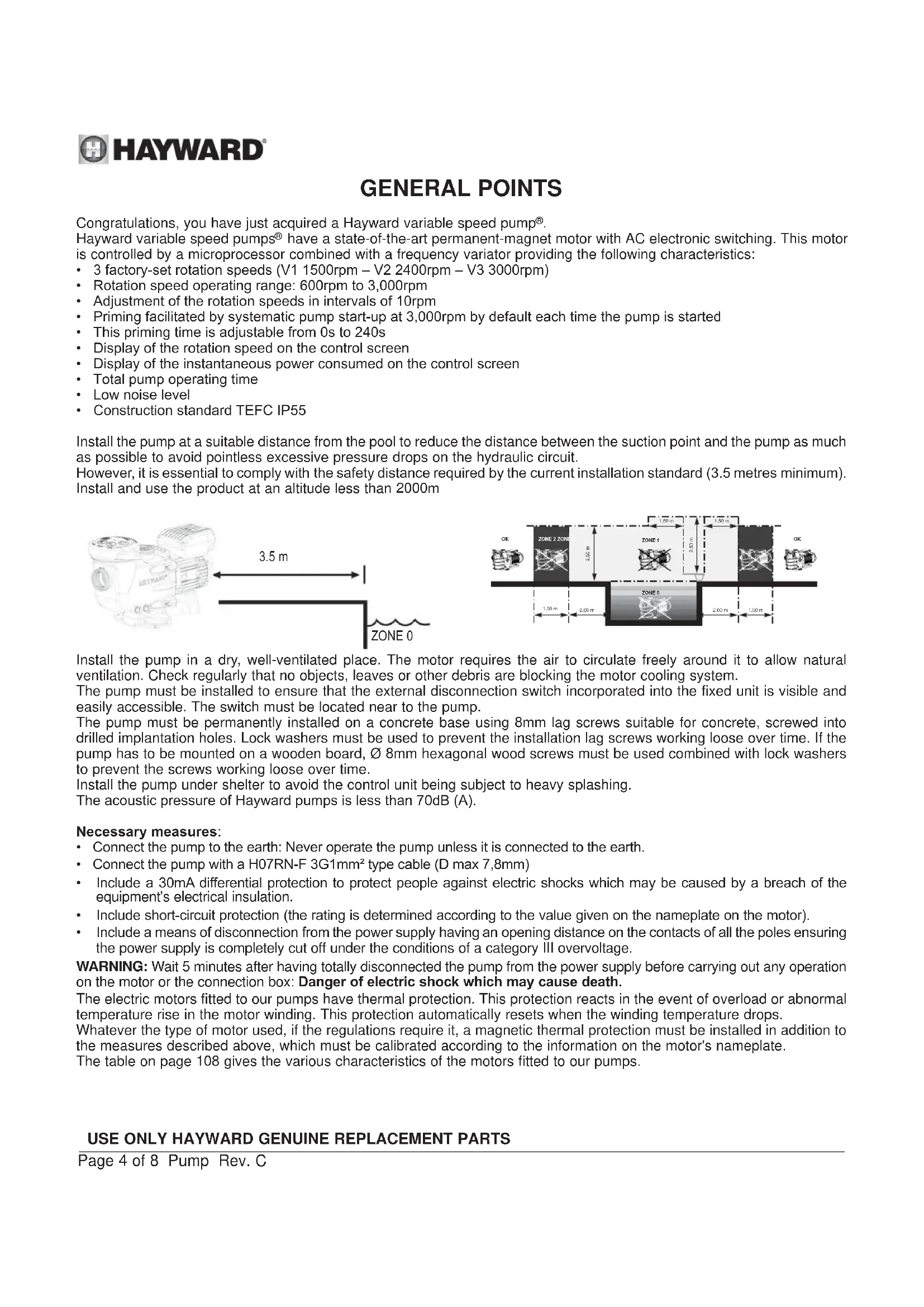
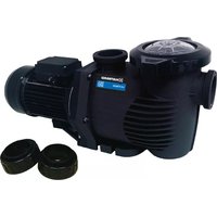
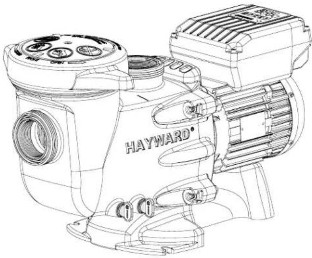
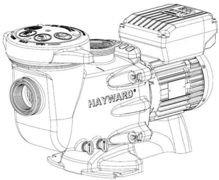
Congratulations, you have just acquired a Hayward variable speed pump®.
Hayward variable speed pumps ^® have a state-of-the-art permanent-magnet motor with AC electronic switching. This motor is controlled by a microprocessor combined with a frequency variator providing the following characteristics:
• 3 factory-set rotation speeds (V1 1500rpm – V2 2400rpm – V3 3000rpm)
• Rotation speed operating range: 600rpm to 3,000rpm
- Adjustment of the rotation speeds in intervals of 10rpm
- Priming facilitated by systematic pump start-up at 3,000rpm by default each time the pump is started
• This priming time is adjustable from 0s to 240s
• Display of the rotation speed on the control screen
• Display of the instantaneous power consumed on the control screen
• Total pump operating time
- Low noise level
• Construction standard TEFC IP55
Install the pump at a suitable distance from the pool to reduce the distance between the suction point and the pump as much as possible to avoid pointless excessive pressure drops on the hydraulic circuit.
However, it is essential to comply with the safety distance required by the current installation standard (3.5 metres minimum). Install and use the product at an altitude less than 2000m
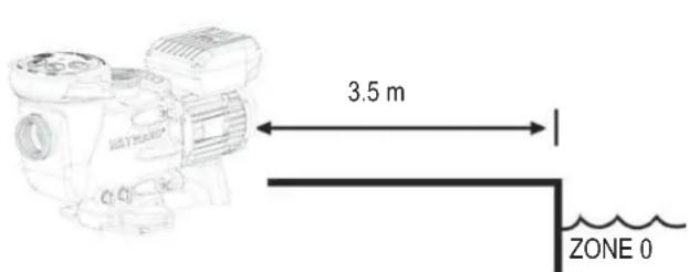
text_image
3.5 m
ZONE 0
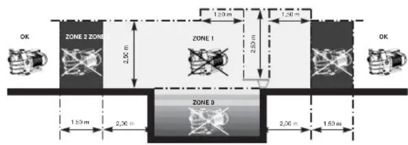
text_image
ZONE 2 ZONE
2.50 m
1.20 m
1.20 m
2.50 m
1.50 m
2.00 m
2.00 m
1.50 m
ZONE 3
ZONE 4
OK
OK
Install the pump in a dry, well-ventilated place. The motor requires the air to circulate freely around it to allow natural ventilation. Check regularly that no objects, leaves or other debris are blocking the motor cooling system.
The pump must be installed to ensure that the external disconnection switch incorporated into the fixed unit is visible and easily accessible. The switch must be located near to the pump.
The pump must be permanently installed on a concrete base using 8mm lag screws suitable for concrete, screwed into drilled implantation holes. Lock washers must be used to prevent the installation lag screws working loose over time. If the pump has to be mounted on a wooden board, ∅ 8mm hexagonal wood screws must be used combined with lock washers to prevent the screws working loose over time.
Install the pump under shelter to avoid the control unit being subject to heavy splashing.
The acoustic pressure of Hayward pumps is less than 70dB (A).
Necessary measures:
- Connect the pump to the earth: Never operate the pump unless it is connected to the earth.
- Connect the pump with a H07RN-F 3G1mm ^2 type cable (D max 7,8mm)
- Include a 30mA differential protection to protect people against electric shocks which may be caused by a breach of the equipment's electrical insulation.
- Include short-circuit protection (the rating is determined according to the value given on the nameplate on the motor).
- Include a means of disconnection from the power supply having an opening distance on the contacts of all the poles ensuring the power supply is completely cut off under the conditions of a category III overvoltage.
WARNING: Wait 5 minutes after having totally disconnected the pump from the power supply before carrying out any operation on the motor or the connection box: Danger of electric shock which may cause death.
The electric motors fitted to our pumps have thermal protection. This protection reacts in the event of overload or abnormal temperature rise in the motor winding. This protection automatically resets when the winding temperature drops.
Whatever the type of motor used, if the regulations require it, a magnetic thermal protection must be installed in addition to the measures described above, which must be calibrated according to the information on the motor's nameplate.
The table on page 108 gives the various characteristics of the motors fitted to our pumps.
USE ONLY HAYWARD GENUINE REPLACEMENT PARTS
Electrical connection: Ensure that the supply voltage required by the motor corresponds to that of the distribution network and that the section and length of the power cable are adapted to the power and current of the pump.
All the electrical connections on the pump and any change of power cable must be done by a qualified professional to avoid any danger.
When carrying out the electrical connections, comply with the identification under the connection terminals.
Check that the electrical connections are correctly tightened and watertight before switching on the power.
Ensure the cable runs correctly through the opening and ferrite provided for this purpose. The cable gland ensures watertightness around the cable, and the ferrite acts as a filter against electromagnetic disturbance.
Any pre-wiring on our pumps must be removed when the pump is permanently connected to the power supply. This preparation is only used for testing at the factory during the manufacturing phases.
INSTALLATION
Install the pool pump so as to reduce pressure drops to a minimum whilst complying with the distances specified in the installation standard, namely 3.5m minimum between the pump and the pool. The suction pipe must be installed with a slight uphill incline towards the pump axis. Ensure that the connections are correctly tightened and watertight. However, avoid excessively tightening the pipes. For plastic materials, use Teflon only to ensure watertightness. The diameter of the suction pipe shall depend on that of the discharge pipe. Avoid damp or non-ventilated locations. The motor requires the cooling air to circulate freely. Install the pump under shelter to avoid the control unit being subject to heavy splashing.
IMPORTANT: Check the direction of rotation before permanently connecting the motor.
INSTRUCTIONS FOR START-UP AND PRIMING: Fill the body of the strainer with water up to the level of the suction pipe.
Never run the pump without water, as the water is necessary for cooling and lubrication of the mechanical shutter. Open all the suction and discharge pipe valves, and the filter air purge valve if there is one. (Any air in the suction pipes must be eliminated). Start up the generator and wait a reasonable time for priming. Five minutes is not excessive for priming (this time depends on the suction head and the length of the suction pipe). If the pump does not start or does not prime, please refer to the troubleshooting guide.
USAGE
Description of the user interface:
The variable speed pump user interface is used to access the settings and speed controls. The up and down buttons are used to adjust the operating speeds and the various settings parameters. The user interface also allows a speed to be saved in place other factory-set speeds.
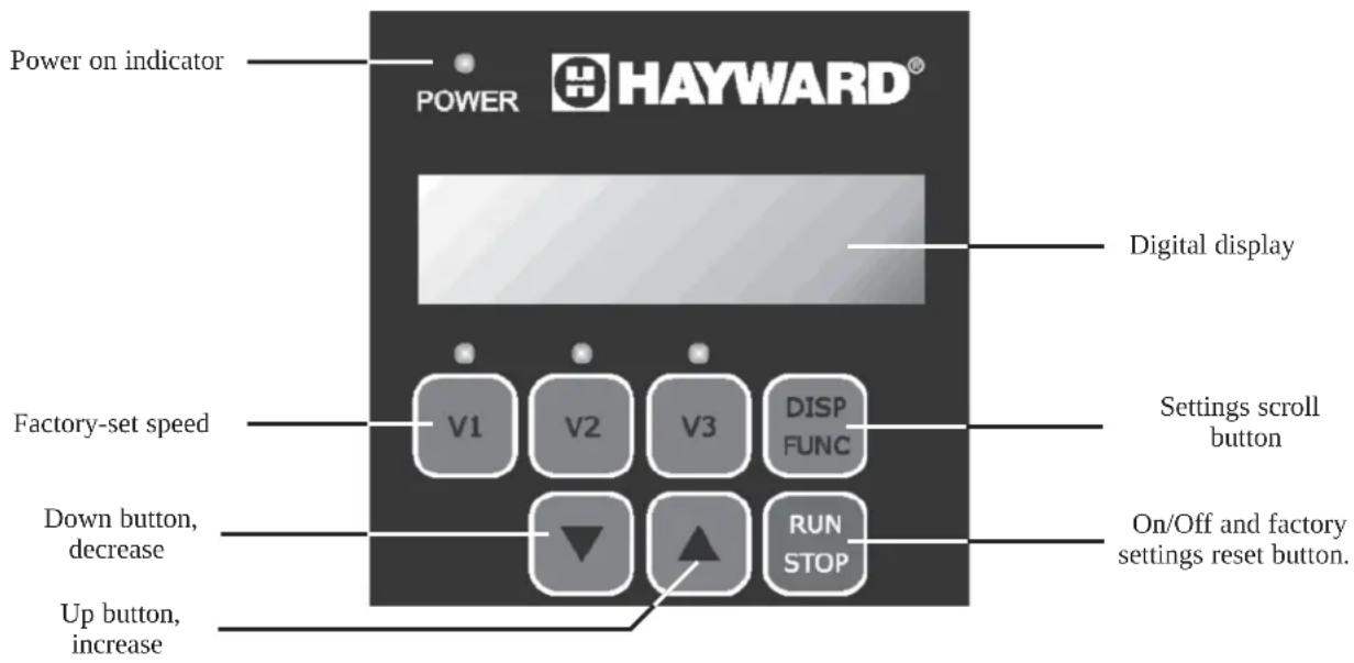
text_image
Power on indicator
POWER HAYWARD®
Digital display
Factory-set speed
V1 V2 V3 DISP FUNC
Down button, decrease
Run STOP
On/Off and factory settings reset button.
Up button, increase
USE ONLY HAYWARD GENUINE REPLACEMENT PARTS
On/Off button:

Press this button to start or stop the pump
This button is also used to shorten the pump priming time => confers Priming time adjustment
When the pump is stopped, the display indicates a rotation speed of 0rpm
If the pump is stopped on purpose or during an unexpected power cut, the pump will start at the maximum speed of 3,000rpm during the configured priming time and will then return to the last speed selected before the shutdown or power cut.
Power on indicator:

The blue indicator lights up when the power to the pump is on
Settings scroll button:

In normal operating mode, the digital display gives the rotation speed
Pressing the DISP/FUNC button once displays the instantaneous power consumed in Watts to +/- 10%. The power display is preceded by the letter P: E.g. P500.
Pressing the DISP/FUNC button a second time will display the total number of operating hours for the pump up to 10,000 hours. The number of hours display is preceded by the letter h: E.g. h10,000.
Pressing the DISP/FUNC button a third time will display the preselected priming time in seconds. The priming time display is preceded by the letter Pr: E.g. Pr60 for a 60-second priming time.
Pressing the DISP/FUNC button a fourth time gives access to the pump reset function. INIT appears on the display. Pressing the DISP/FUNC button a fifth time displays the version of the electronic driver. Display of the version is preceded by the letters Id: E.g. Id 100.
Pressing the DISP/FUNC button a sixth time displays the temperature of the electronic power module. The temperature display is preceded by the letter t: E.g. t 85°C
Factory-set speed:

Buttons V1, V2 and V3 are used to select one of the three factory-set speeds.
The factory-set speeds are:
V1 = 1,500rpm
V2 = 2,400rpm
V3 = 3,000rpm
The blue LED indicates that the speed has been correctly selected.
Up and Down buttons:

The Up/Down buttons are used to increase or decrease the rotation speed when the pump is operating. If the pump is in default settings reset mode, pressing the Up and Down buttons once confirms the reset.
Selecting and adjusting the pump speeds:
Hayward variable speed pumps ^® use factory-set rotation speeds. To select a speed, ensure that the pump is switched on and press the speed of your choice. The blue indicator lights up to indicate that the selection has been recognised. Then press the On/Off button to start the pump.
N.B. Whatever speed is selected, the pump starts in priming mode at 3,000rmp by default for the preset time (60 seconds default factory setting) before automatically returning to the selected rotation speed or the speed previously selected.
It is also possible to set rotation speeds other than those preset in the factory in the range 600rmp to 3,000rpm.
- =Ensure the pump is switched on
- =Select one of the preset speeds to modify it
- = Press the up or down button to increase or decrease this speed by 10rpm intervals. One long press gives faster scrolling.
USE ONLY HAYWARD GENUINE REPLACEMENT PARTS

HAYWARD®
- Press on the button for the selected speed until the blue LED flashes to validate your new setting. The blue LED indicates that the new stetting has been correctly saved.
- =The new speed now appears on the display and will be saved in the memory.
Ensure you do not run the pump at a speed generating a water flow higher than the capacity of the installation (filter, pipes, etc.) or too low for the equipment in your installation. If in doubt consult a professional to ensure the pump is correctly set.
Adjusting the priming time:
In certain cases it may be necessary to adjust the priming time to allow the air in the hydraulic pipes to be evacuated.
This priming time will be applied each time the pump is started.
The priming time can be adjusted from 0 to 240 seconds (4 minutes).
To modify the priming time:
- =Ensure the pump is switched on
- =Press the DISP/FUNC button three times until «Pr» appears, indicating the priming menu.
=The priming time is 60 seconds by default (PR60).
- =Use the Up/Down buttons to increase or decrease the priming time.
The setting is adjusted second by second within the range 0-240 seconds
- =Any change will automatically be saved.
Once the time setting has been changed, the pump will start by default at 3,000rpm for the duration of the new priming time.
When the pump is operating in priming mode, a digital bar turns in a circle on the left of the display.
Note: The priming function can be interrupted at any time by a short press on the On/Off button.
Restoring the factory settings:
To restore the factory settings and erase all the settings, proceed as follows:
- =Ensure the pump is switched on
- =Ensure the pump is not running
- =Press 4 times on the DISP/FUNC button until INIT is displayed
- =Press the Up button for approximately 3 seconds. The message «DONE» appears
The factory settings have been successfully restored.
The default settings are:
V1 = 1,500rpm
V2 = 2,400rpm
V3 = 3,000rpm
«Pr» 60-second priming time.
MAINTENANCE
- Completely disconnect the pump from the mains power supply before opening the cover and cleaning the strainer. Clean the strainer basket regularly. Do not bang on the basket to clean it. Check the seal on the cover of the strainer and replace it if necessary.
- The motor shaft is mounted on self-lubricating bearings which do not require any subsequent lubrication.
- Keep the motor clean and dry and ensure the ventilation openings are not blocked.
- The mechanical shutter occasionally starts to leak and must then be changed
- Apart from cleaning the pool, all repairs, servicing and maintenance must be carried out by a Hayward-approved agent or a qualified person.
WINTERING
-
Empty the pump by removing all the drain plugs and store them in the strainer basket.
-
Disconnect the pump, remove the pipe connectors and store the entire unit in a dry, well-ventilated place or at least take the following precaution: disconnect the pump, remove the 4 bolts attaching the pump housing to the motor bracket and store the unit in a dry, well-ventilated place. Then cover the pump housing and strainer to protect them.
N.B.: Before recommissioning the pump, clean all the internal parts to remove dust, lime scale etc.
USE ONLY HAYWARD GENUINE REPLACEMENT PARTS
TROUBLESHOOTING
A) The motor does not start
- Check the electrical connections, switches or relays, and the circuit breaker or fuses.
- Ensure that the motor turns freely by hand.
- Check that rotation speeds V1, V2 and V3 are not programmed at 0rpm. If they are, restore the factory settings.
- Continuous line undervoltage Error code (1) appears on the digital display
- Continuous line overvoltage Error code (2) appears on the digital display
- Electricity supply problem inside the motor Error code (10)
- Internal short circuit problem Error code (64)
- Communication problem Error code (98)
- Failed start 5 times in 2 minutes Error code (20) appears on the digital display.
RSTRT is displayed during attempts to start.
- Multiple problems Error code (97) appears on the digital display.
B) The motor stops, check
- The cables, connections, relays etc.
- Voltage drop on motor (frequently caused by cables that are too small).
- That there is no seizing or overheating (by reading the absorbed current).
N.B.: The motor on your pump is fitted with a thermal protection which, in the case of overload, will automatically cut the circuit and avoid the motor being damaged. This triggering is caused by abnormal usage conditions which need to be checked and corrected. The motor will restart without any intervention as soon as normal operating conditions are restored.
C) The motor growls but does not start, check that a phase is not cut, the capacitor is not damaged.
D) "OLOAD" appears on the display (overload or over-heating problem)
- Check that the motor shaft turns freely
- Check that no debris is preventing the turbine from rotating freely
- Check that the motor is correctly ventilated
- After correcting the problem, press the On/Off button
E) The pump does not prime
- Ensure the strainer housing is filled with water, that the cover seal is clean and correctly positioned and that no air can enter. If necessary, tighten the cover lock screws.
- Ensure that all the suction and discharge valves are open and not blocked and that the suction outlets in the pool are fully submerged.
- Check that the pump draws by freeing the suction as close as possible to the pump:
a) if the pump does not draw despite being sufficiently full of priming water
- Tighten the bolts and pipe accessories on the suction side.
- Check the voltage to ensure that the pump is rotating at the correct speed.
- Open the pump and check that nothing is blocking it inside,
- Replace the mechanical shutter.
b) If the pump is drawing normally, check the suction pipe and strainer which may be blocked or be allowing air to enter.
- That no air is entering the suction side and causing dull crackling in the pump.
- That there is no cavitation caused by insufficient diameter or a restriction in the suction tube. An over-sized discharge pipe can also cause cavitation. Use pipes of the correct size or purge the pipes if necessary.
- That no vibration is occurring due to incorrect fitting.
- That there are no foreign bodies in the pump housing.
- That the motor bearings have not seized due to excessive clearance, rust or prolonged overheating.
USE ONLY HAYWARD GENUINE REPLACEMENT PARTS

natural_image
Abstract geometric logo with stylized letter 'H' inside a circular frame (no text or symbols)
HAYWARD®

natural_image
Technical line drawing of a Hayward electric motor (no text or symbols on the diagram itself)

text_image
CE i
BOMBA CENTRÍFUGA DE VELOCIDAD VARIABLE
MANUAL DEL USUARIO
CONSERVE ESTE MANUAL PARA CONSULTARLO POSTERIORMENTE

natural_image
Abstract geometric logo with stylized letter H inside a circular frame (no text or symbols)
HAYWARD®

natural_image
Technical line drawing of a Hayward electric motor (no text or symbols on the diagram itself)

text_image
CE i
BOMBA CENTRÍFUGA DE VELOCIDADE VARIÁVEL
MANUAL DO UTILIZADOR
CONSERVE ESTE MANUAL PARA REFERÊNCIA FUTURA

http://www.hayward.fr/en/services/register-your-product

natural_image
Abstract geometric logo with stylized letter H inside a circular frame (no text or symbols)
HAYWARD®

natural_image
Technical line drawing of a Hayward electric motor (no text or symbols on the diagram itself)

text_image
CE i
ZENTRIFUGALPUMPE MIT VARIABLER GESCHWINDIGKEIT
ANWENDER - HANDBUCH
natural_image
Abstract geometric logo with stylized letter H inside a circular frame (no text or symbols)
HAYWARD®

natural_image
Technical line drawing of a Hayward electric motor (no text or symbols on the diagram itself)

text_image
CE i
CENTRIFUGAALPOMP MET VARIABELE SNELHEID
GEBRUIKERSHANDBOEK
DIT HANDBOEK BEWAREN VOOR TOEKOMSTIG GEBRUIK

http://www.hayward.fr/en/services/register-your-product

natural_image
Abstract geometric logo with stylized letter 'H' inside a circular frame (no text or symbols)
HAYWARD®

natural_image
Technical line drawing of a Hayward electric motor (no text or symbols on the diagram itself)

text_image
CE i
POMPA CENTRIFUGA A VELOCITÀ VARIABILE
MANUALE PER L'USO
http://www.hayward.fr/en/services/register-your-product

Dati da conservare
natural_image
Abstract geometric logo with stylized letter H inside a circular frame (no text or symbols)
HAYWARD®

natural_image
Technical line drawing of a Hayward electric motor (no text or symbols on the diagram itself)

text_image
CE i
CENTRIFUGALPUMP MED VARIABELT VARVTAL
ANVÄNDARHANDLEDNING
SPARA DENNA HANDLEDNING FÖR SENARE REFERENS

http://www.hayward.fr/en/services/register-your-product

För dina noteringar
natural_image
Abstract geometric logo with stylized letter 'H' inside a circular frame (no text or symbols)
HAYWARD®

natural_image
Technical line drawing of a Hayward electric motor (no text or symbols on the diagram itself)

text_image
CE i
CENTRIFUGEPUMPE MED VARIABEL HASTIGHED
BRUGERVEJLEDNING
OPBEVAR DENNE MANUAL TIL SENERE BRUG
http://www.hayward.fr/en/services/register-your-product

Side 4 af 8 Pumpe Rev. C
Side 6 af 8 Pumpe Rev. C
Side 7 af 8 Pumpe Rev. C
MULIGE FEJLKILDER OG L∅SNINGER
natural_image
Abstract geometric logo with stylized letter H inside a circular frame (no text or symbols)
HAYWARD®

natural_image
Technical line drawing of a Hayward electric motor (no text or symbols on the diagram itself)

text_image
CE i
SENTRIFUGALPUMPE MED VARIABEL HASTIGHET
BRUKERVEILEDNING
TA VARE PÅ DENNE VEILEDNINGEN FOR SENERE BRUK

http://www.hayward.fr/en/services/register-your-product

natural_image
Abstract geometric logo with stylized letter H inside a circular frame (no text or symbols)
HAYWARD®

natural_image
Technical line drawing of a Hayward electric motor (no text or symbols on the diagram itself)

text_image
CE i
KESKIPAKOPUMPPU SÄÄDETTÄVÄLLÄ NOPEUDELLA
KÄYTTÖOHJE
SÄILYTÄ TÄMÄ KÄYTTÖOHJE MYÖHEMPÄÄ TARVETTA VARTEN

MAHDOLLISET VIAT JA RATKAISUT
natural_image
Abstract geometric logo with stylized letter H inside a circular frame (no text or symbols)
HAYWARD®

natural_image
Technical line drawing of a Hayward electric motor (no text or symbols on the diagram itself)

text_image
CE i
http://www.hayward.fr/en/services/register-your-product

Для Вашего сведения
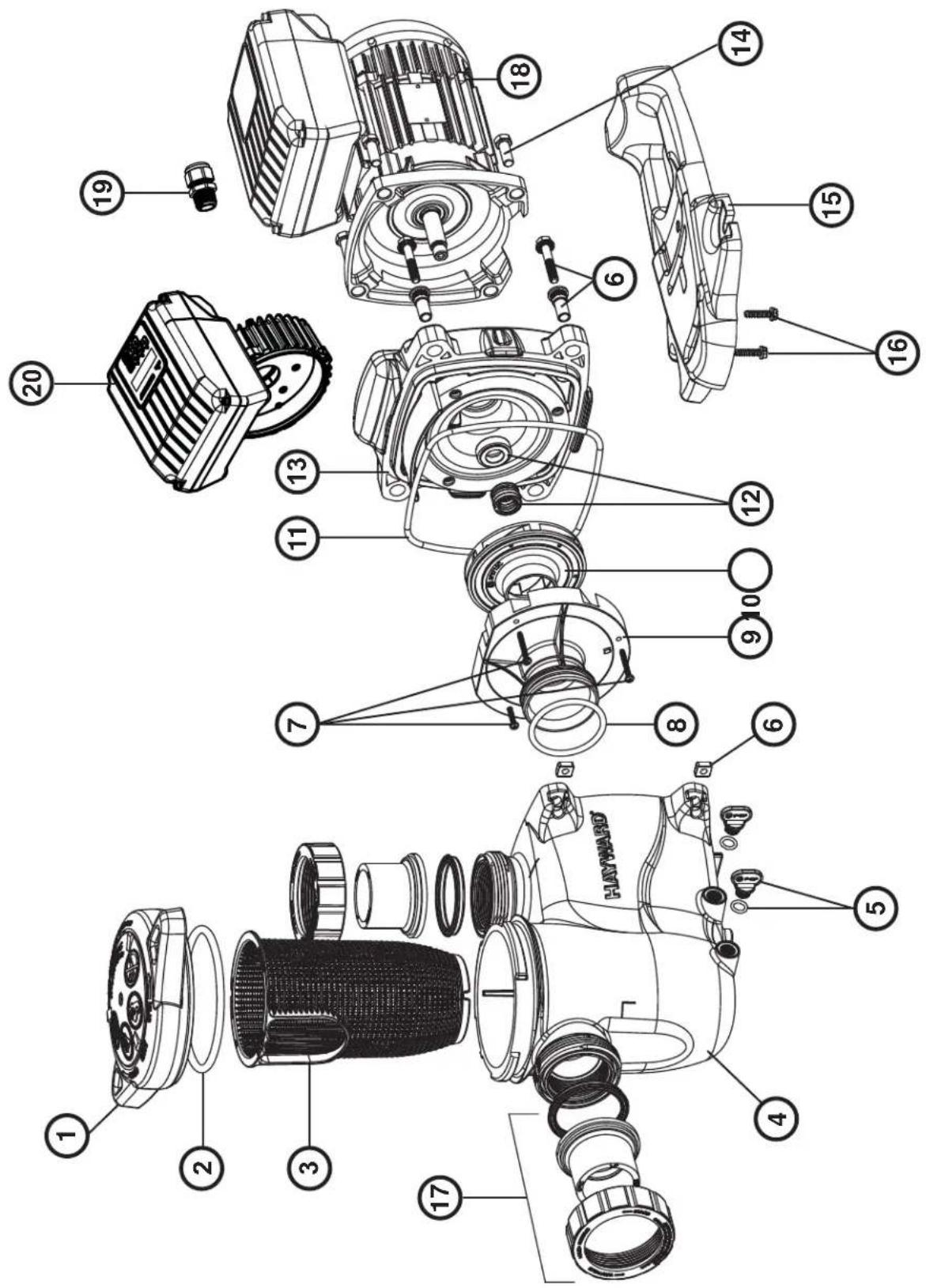
text_image
Exploded view diagram of a Hayward motor assembly with numbered parts for identification
| N° SP3216VS N° SP3216VS | | |
| 1 SPX3200DLS 13 SPX3200SA | | |
| 2 SPX3200S 14 SPX3200T | | |
| 3 SPX3200M 15 SPX3200E | | |
| 4 SPX3200A 16 SPX3200Z3 | | |
| 5 SPX4000FG 17 SPX3200Z5 | | |
| 6 SPX3200Z211 18 SPX1100SFVS | | |
| 7 SPX4000Z1 19 SPX3200GA | | |
| 8 SPX3200Z8 20 SPX3200GC | | |
| 9 SPX3200B3 21 SPX1100PE | | |
| 10 SPX3200Z1 22 SP3200UNKIT63 | | |
| 11 SPX3021R 23 SPX1100ELVS | | |
| 12 SPX3215C | | |
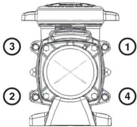
Ordre de serrage des boulons - Bolt tightening order - Orden de apriete de los pernos - Ordem de aperto dos parafusos - Anzugsreihenfolge der Bolzen - Volgorde waarin de bouten vastgedraaid moeten worden - Ordine di stringimento bulloni - Ordning för att dra åt bultarna - Spændngsrækkefølge for bolte - Rekkefølge for tiltrekking av boltene - Pulttien kiristysjärjestys - Порядок затяжки болтов
185 INCH LBS
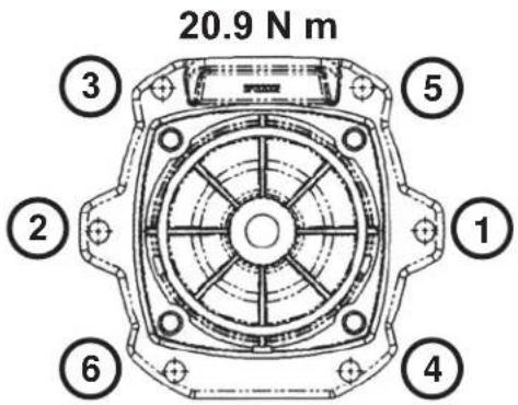
text_image
20.9 N m
③
⑤
②
①
⑥
④
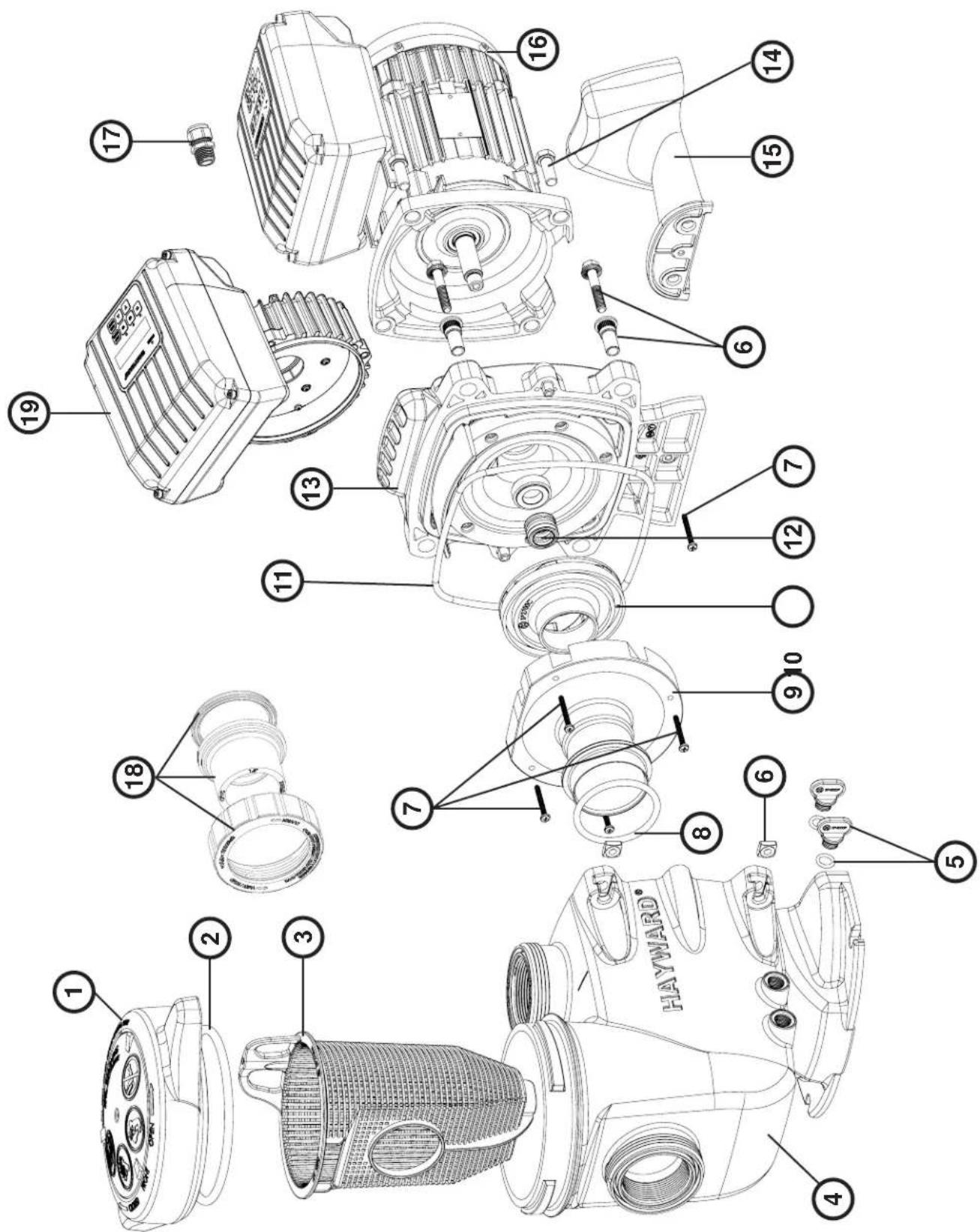
text_image
Exploded view diagram of a HAYAMAR electric motor with numbered parts for identification
| N° SP2315VS N° SP2315VS | | |
| 1 SPX2300DLS 11 GMX600F | | |
| 2 SPX2300Z4 12 SPX2700SA | | |
| 3 SPX2300M 13 SPX2300E | | |
| 4 SPX2300AA 14 SPX3200Z5PAK4 | | |
| 5 SPX4000FG 15 SPX2300G | | |
| 6 | SPX2700ZPAK | 16 | SPX1600Z52 |
| 7 | SPX2300Z3PAK3 | 17 | SP2700UNKIT50 |
| 8 | SX220Z2 | 18 | SPX1100SFVS |
| 9 SPX2300B 19 SPX1100PE | | |
| 10 | SPX2300CVS | 20 | SPX1100ELVS |
Ordre de serrage des boulons - Bolt tightening order - Orden de apriete de los pernos - Ordem de aperto dos parafusos - Anzugsreihenfolge der Bolzen - Volgorde waarin de bouten vastgedraaid moeten worden - Ordine di stringimento bulloni - Ordning för att dra åt bultarna - Spændngsrækkefølge for bolte - Rekkefølge for tiltrekking av boltene - Pulttien kiristysjärjestys - Порядок затяжки болтов
185 INCH LBS
20.9 N m

text_image
Technical diagram of a mechanical device with numbered parts labeled 1 to 4
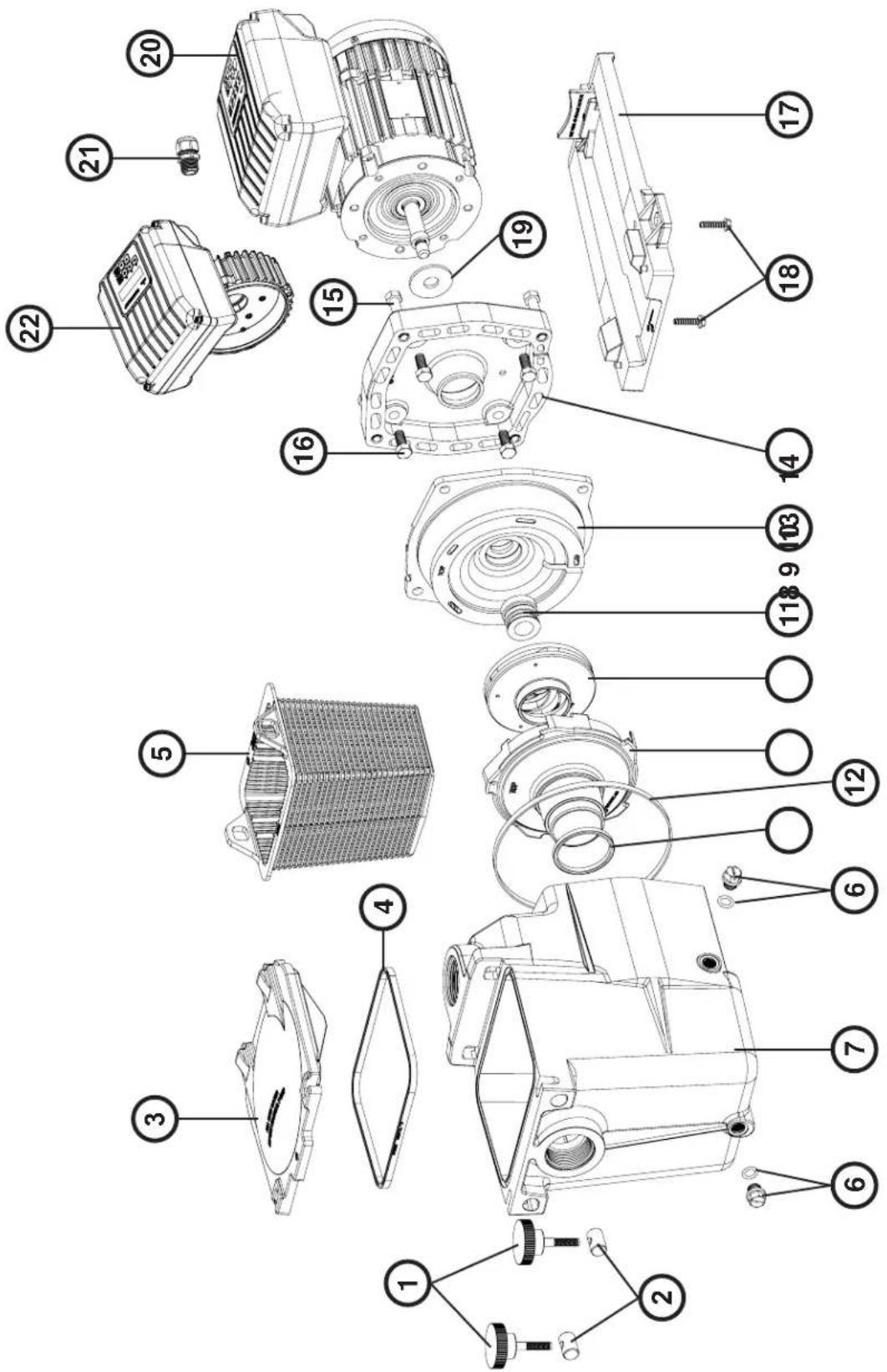
text_image
Exploded view diagram of a Hayward motor assembly with numbered parts for identification
| N° SP2715VS |
| 1 SPX2700DLS |
| 2 SPX2700Z4 |
| 3 SPX2700M |
| 4 SPX2700AA |
| 5 SPX4000FG |
| 6 SPX2700ZPAK |
| 7 SPX2700Z3 |
| 8 SX220Z2 |
| 9 + 12 + 13 SPX2700ESA3 |
| 10 SPX2715C |
| 11 GMX0600F |
| 14 SPX3200Z5 |
| 15 SPX2700G |
| 16 SPX1100SFVS |
| 17 SPX1100PE |
| 18 | SP2700UNKIT50 |
| 19 | SPX1100ELVS |
Ordre de serrage des boulons - Bolt tightening order - Orden de apriete de los pernos - Ordem de aperto dos parafusos - Anzugsreihenfolge der Bolzen - Volgorde waarin de bouten vastgedraaid moeten worden - Ordine di stringimento bulloni - Ordning för att dra åt bultarna - Spændngsrækkefølge for bolte - Rekkefølge for tiltrekking av boltene - Pulttien kiristysjärjestys - Порядок затяжки болтов
185 INCH LBS
20.9 N m
text_image
Technical diagram of a mechanical component with numbered parts labeled 1 to 4
text_image
Exploded view diagram of an electric motor assembly with numbered parts for identification
| N° SP2616VS |
| 1 + 2 SPX1600PN |
| 3 SPX1600D |
| 4 SPX1600S |
| 5 SPX1600M |
| 6 SPX1700FG |
| 7 SPX1620AE |
| 8 SPX1600R |
| 9 SPX2600BE |
| 10 SPX2615CE |
| 11 SPX1600Z2 |
| 12 SPX1600T |
| 13 + 14 SPX2600EKIT |
| 15 SPX1600Z4 |
| 16 | SPX0125Z4E |
| 17 | SPX2600G1 |
| 18 SPX1600Z5 |
| 19 SPX0125F |
| 20 | SPX1100VS |
| 21 | SPX1100PE |
| 22 | SPX1100ELVS |
GARANTIE LIMITÉE
All HAYWARD products are covered for manufacturing defects or material defects for a warranty period of 2 years as of date of purchases. Any warranty claim should be accompanied by evidence of purchase, indicating date of purchase. We would therefore advise you to keep your invoice.
The HAYWARD warranty is limited to repair or replacement, as chosen by HAYWARD, of the faulty products, provided that they have been subjected to normal use, in compliance with the guidelines given in their user guides, provided that the products have not been altered in any way, and provided that they have been used exclusively with HAYWARD parts and components. The warranty does not cover damage due to frost and to chemicals. Any other costs (transport, labour, etc.) are excluded from the warranty.
HAYWARD may not be held liable for any direct or indirect damage resulting from incorrect installation, incorrect connection, or incorrect operation of a product.
In order to claim on a warranty and in order to request repair or replacement of an article, please ask your dealer.
No equipment returned to our factory will be accepted without our prior written approval.
Wearing parts are not covered by the warranty.
GARANTÍA LIMITADA
BESCHRÄNKTE GARANTIE