
TriStar - Pump HAYWARD - Free user manual and instructions
Find the device manual for free TriStar HAYWARD in PDF.
| Product type | Pool pump |
| Brand | Hayward |
| Model | TriStar |
| Power supply | 230 V single-phase or three-phase (depending on version) |
| Residual current protection | 30 mA circuit breaker |
| Thermal protection | Yes (automatic reset) |
| Maximum water temperature | 35 °C |
| Maximum installation altitude | 2000 m |
| Sound pressure | < 70 dBA |
| Power cable | 3G1.5 mm² type H07RN-F |
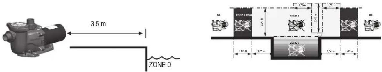
| Minimum distance from pool | 3.5 m (according to standard NF C 15-100) |
| Motor type | Single-phase or three-phase |
| Warranty | 3 years |
| Routine maintenance | Regular cleaning of the prefilter basket |
| Wear parts | Mechanical seal, bearings, gaskets, capacitor |
| Estimated wear parts life | Seal: 1 year, Bearings: 1 year, Gaskets: 2 years, Capacitor: 2 years |
| Winterizing | Drain, disconnect, store dry |
| Repairability | Use of genuine Hayward spare parts |
| Standards | IEC 60364-7-702:2010, NF C 15-100 |
| Usage | Private pool |
Frequently Asked Questions - TriStar HAYWARD
User questions about TriStar HAYWARD
0 question about this device. Answer the ones you know or ask your own.
Ask a new question about this device
Download the instructions for your Pump in PDF format for free! Find your manual TriStar - HAYWARD and take your electronic device back in hand. On this page are published all the documents necessary for the use of your device. TriStar by HAYWARD.
USER MANUAL TriStar HAYWARD
natural_image
Abstract geometric logo with stylized letter H inside a circular frame (no text or symbols)HAYWARD®

natural_image
Line drawing of a mechanical pump or motor assembly (no text or symbols)
natural_image
Line drawing of a mechanical pump or motor assembly (no text or symbols)
GUIDE DE L'UTILISATEUR
USER'S GUIDE
MANUAL DEL USUARIO
MANUAL DO UTILIZADOR
ANWENDERHANDBUCH
GEBRUIKERSHANDLEIDING
MANUALE D'USO
ANVÄNDARHANDBOK
natural_image
Abstract geometric logo with stylized letter H inside a circular frame (no text or symbols)HAYWARD®
natural_image
Line drawing of a mechanical pump or motor assembly (no text or symbols)
natural_image
Line drawing of a mechanical pump or motor assembly (no text or symbols)
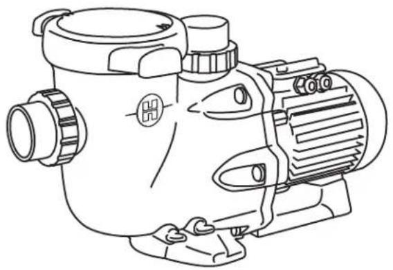
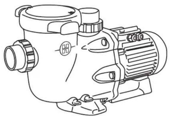
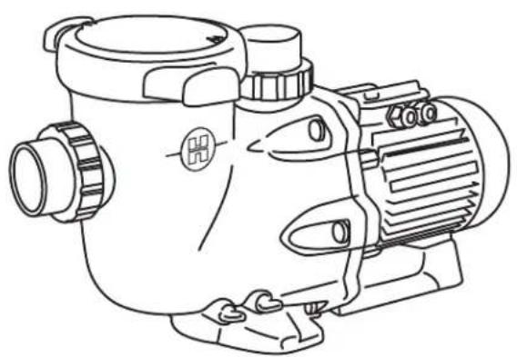
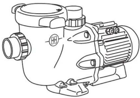
POMPE CENTRIFUGE
GUIDE DE L'UTILISATEUR
CONSERVEZ CE MANUEL POUR UNE CONSULTATION ULTÉRIEURE

HAYWARD®

natural_image
Abstract geometric logo with stylized letter H inside a circular frame (no text or symbols)HAYWARD®

natural_image
Line drawing of a mechanical pump or motor assembly (no text or symbols)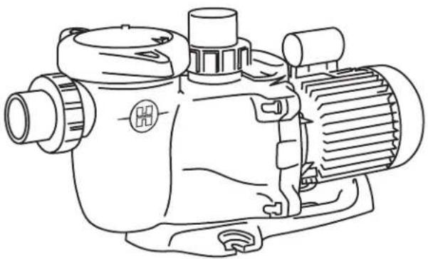
natural_image
Line drawing of an electric motor with cooling fins and housing (no text or symbols)
CENTRIFUGAL PUMP
USER GUIDE
KEEP THIS MANUAL FOR FUTURE REFERENCE

WARNING: Electrical Hazard. Failure to follow instructions can result in serious injury or death. FOR USE WITH SWIMMING POOLS
⚠ WARNING – Disconnect the pump from the main power supply completely before servicing the pump or filter.
△ WARNING – All electrical connections must be done by a qualified electrician according to local electrical standard or, failing that, to the International Standard IEC 60364-7-702:2010.
△ WARNING – Be certain the machine is only plugged into a protected 230 V\~ outlet that is protected from short-circuits. The pump is to be supplied by an isolating transformer or supplied through a residual current device (RCD) having a rated residual operating current not exceeding 30 mA.
⚠ WARNING – Children should be supervised to ensure that they do not play with the appliance. Keep fingers and foreign objects away from openings and moving parts.
△ WARNING – Motor must be suitably grounded. Connect ground wire to green grounding screw and for cord connected units use properly grounded outlet.
⚠ WARNING – Use a motor bonding lug to connect motor with other bonded parts using the appropriate size conductor as required by electrical codes.
△ WARNING – When making these electrical connections, refer to the diagram given under the lid of the motor terminal box. Be sure to check the electric connections are tight and sealed before powering up. Replace all covers before operation.
△ WARNING – Make sure that the power supply voltage required by the motor corresponds to that of the distribution network and that the power supply cables matches the power and current of the pump.
⚠ WARNING – Read and follow all instructions in this owner's manual and on the equipment. Failure to follow instructions can cause serious injury or death.
This document should be given to the owner of the swimming pool and must be kept by the owner in a safe place.
△ WARNING – The appliance can be used by children aged from 8 years and above and persons with reduced physical, sensory or mental capabilities, or lack of experience and knowledge, if they have been given supervision or instruction concerning use of the appliance in a safe way and understand the hazards involved.
⚠ WARNING – Cleaning and user maintenance shall not be made by children without supervision.
⚠ WARNING – The pump is intended for continuous operation at Maximum Water temperature 35°C.
⚠ WARNING – Use Only Genuine Hayward® Replacement Parts.
⚠ WARNING – If the supply cord is damaged it must be replaced by the manufacturer, service agent, or similarly qualified persons in order to avoid a hazard.
⚠ WARNING – For disconnection from main power supply an external switch having a contact separation in all poles that provide a full disconnection under overvoltage category III conditions must be incorporated in the fixed wiring in accordance with the wiring rules.
⚠ WARNING – Do not operate the swimming pool pump if the power cord or the housing of the motor connection box is damaged. This can cause an electric shock. A damaged power cord or motor connection box must be replaced by a service agent or a similarly qualified person immediately in order to avoid a hazard.
△ WARNING – This pool motor is NOT equipped with a Safety Vacuum Release System (SVRS). SVRS helps prevent drowning due to body entrapment on underwater drains. In some pool configuration, if a person's body covers the drain, the person can be trapped by suction. Depending on your pool configuration, a SVRS may be required to meet local requirements.
USE ONLY HAYWARD
® GENUINE REPLACEMENT PARTS
GENERAL POINTS
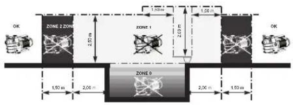
Install the pump at a suitable distance from the pool to reduce the distance between the suction point and the pump as much as possible to avoid pointless excessive pressure drops on the hydraulic circuit.
However, it is essential to comply with the safety distance required by the current installation standard (3.5 metres minimum). Install and use the product at an altitude less than 2000m
Install the pump in a dry, well-ventilated place. The motor requires the air to circulate freely around it to allow natural ventilation. Check regularly that no objects, leaves or other debris are blocking the motor cooling system.
The pump must be installed to ensure that the external disconnection switch incorporated into the fixed unit is visible and easily accessible. The switch must be located near to the pump.
The pump must be permanently installed on a concrete base using 8mm lag screws suitable for concrete, screwed into drilled implantation holes. Lock washers must be used to prevent the installation lag screws working loose over time. If the pump has to be mounted on a wooden board, ∅ 8mm hexagonal wood screws must be used combined with lock washers to prevent the screws working loose over time.
The acoustic pressure of Hayward® pumps is less than 70dBA.
Necessary measures:
- Connect the pump to the earth: Never operate the pump unless it is connected to the earth.
- Connect the pump with a H07RN-F 3G1,5mm ^2 type cable.
- Include a 30mA differential protection to protect people against electric shocks which may be caused by a breach of the equipment's electrical insulation.
- Include short-circuit protection (the rating is determined according to the value given on the nameplate on the motor).
- Include a means of disconnection from the power supply having an opening distance on the contacts of all the poles ensuring the power supply is completely cut off under the conditions of a category III overvoltage.
Single phase electric motor:
The single phase motors fitted to our pumps are provided with thermal protection. This protection operates on an overload or in the event of abnormal heating of the motor coil and is reset automatically when the winding temperature drops.
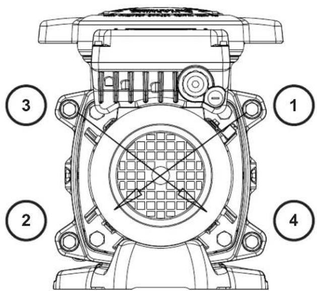
Three phase electric motor:
On three phased motors the internal heat protection (screw terminal blocks [icon] ) is to be connected serially in the pump's power contactor command line.
Check the running direction of the pump motor (a label is provided on the motor housing to indicate the motor running direction).
If so required by regulations and whatever the motor type, in addition to the devices mentioned above, it is also necessary to install a thereto-magnetic protective device calibrated in accordance with the indications on the motor name-plate.
The table on page 49 indicates the various characteristics of the motors fitted to our pumps.
USE ONLY HAYWARD
® GENUINE REPLACEMENT PARTS
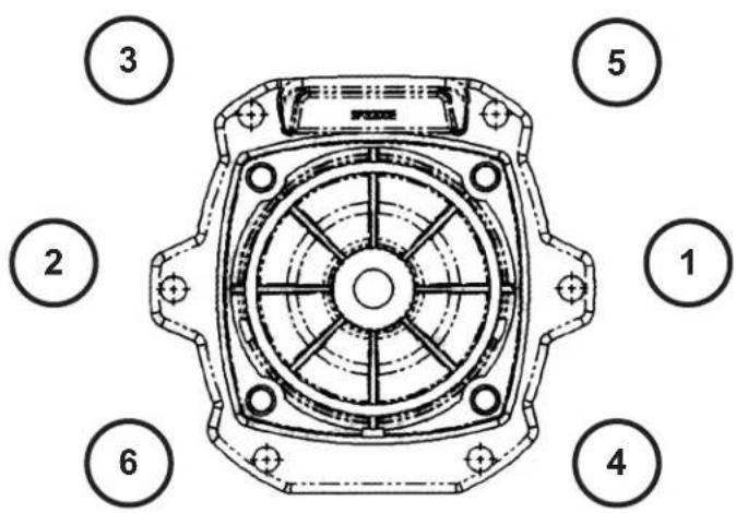
Electrical connection: Make sure that the power supply voltage required by the motor corresponds to that of the distribution network and that the power supply cables matches the power and current of the pump.
All the electric connections of the pump and the possible change of power supply cable must be hand-led by a qualified professional so as to avoid all possible danger.
When making these electrical connections, refer to the diagram given under the lid of the motor terminal box.
Be sure to check the electric connections are tight and sealed before powering up.
The pre-wiring that might be included on some of the pumps must be removed for final connection of the pump to the electric power supply. This pre-equipment is only used for works testing during the manufacturing phases.
INSTALLATION
Install the pool pump so as to reduce pressure drops to a minimum whilst complying with the distances specified in the installation standard, namely 3.5m minimum between the pump and the pool. The suction pipe must be installed with a slight uphill incline towards the pump axis. Ensure that the connections are correctly tightened and watertight. However, avoid excessively tightening the pipes. For plastic materials, use Teflon only to ensure watertightness. The diameter of the suction pipe shall depend on that of the discharge pipe. Avoid damp or non-ventilated locations. The motor requires the cooling air to circulate freely.
IMPORTANT: Check the direction of rotation before permanently connecting the motor.
INSTRUCTIONS FOR START-UP AND PRIMING: Fill the body of the strainer with water up to the level of the suction pipe. Never run the pump without water, as the water is necessary for cooling and lubrication of the mechanical shutter. Open all the suction and discharge pipe valves, and the filter air purge valve if there is one. (Any air in the suction pipes must be eliminated). Start up the generator and wait a reasonable time for priming. Five minutes is not excessive for priming (this time depends on the suction head and the length of the suction pipe). If the pump does not start or does not prime, please refer to the troubleshooting guide.
MAINTENANCE
-
Completely disconnect the pump from the mains power supply before opening the cover and cleaning the strainer. Clean the strainer basket regularly. Do not bang on the basket to clean it. Check the seal on the cover of the strainer and replace it if necessary.
-
The motor shaft is mounted on self-lubricating bearings which do not require any subsequent lubrication.
-
Keep the motor clean and dry and ensure the ventilation openings are not blocked.
-
The mechanical seal occasionally starts to leak and must then be changed.
-
Apart from cleaning the pool, all repairs, servicing and maintenance must be carried out by a Hayward®-approved agent or a qualified person.
Wear parts of the pump mentioned below should be maintained according to their estimated life:
| Wear parts | Estimated | life | |||||
| Mechanical seal | 1 | year | |||||
| Motor bearings kit | 1 | year | |||||
| Set of gasket (strainer, housing, bulkheads, drain) | 2 years | ||||||
| Capacitor | 2 | years | |||||
WINTERING
-
Empty the pump by removing all the drain plugs and store them in the strainer basket.
-
Disconnect the pump, remove the pipe connectors and store the entire unit in a dry, well-ventilated place or at least take the following precaution: disconnect the pump, remove the 4 bolts attaching the pump housing to the motor bracket and store the unit in a dry, well-ventilated place. Then cover the pump housing and strainer to protect them.
N.B.: Before recommissioning the pump, clean all the internal parts to remove dust, lime scale etc.
USE ONLY HAYWARD
® GENUINE REPLACEMENT PARTS
TROUBLESHOOTING
A) The motor does not start
-
Check the electrical connections, switches or relays, and the circuit breaker or fuses.
-
Ensure that the motor turns freely by hand.
B) The motor stops, check
- The cables, connections, relays etc.
- Voltage drop on motor (frequently caused by cables that are too small).
- That there is no seizing or overheating (by reading the absorbed current).
N.B.: The motor on your pump is fitted with a thermal protection which, in the case of overload, will automatically cut the circuit and avoid the motor being damaged. This triggering is caused by abnormal usage conditions which need to be checked and corrected. The motor will restart without any intervention as soon as normal operating conditions are restored.
C) The motor growls but does not start, check that a phase is not cut, the capacitor is not damaged.
D) The pump does not prime
- Ensure the strainer housing is filled with water, that the cover seal is clean and correctly positioned and that no air can enter. If necessary, tighten the cover lock screws.
- Ensure that all the suction and discharge valves are open and not blocked and that the suction outlets in the pool are fully submerged.
- Check that the pump draws by freeing the suction as close as possible to the pump:
a) if the pump does not draw despite being sufficiently full of priming water - Tighten the bolts and pipe accessories on the suction side.
- Check the voltage to ensure that the pump is rotating at the correct speed.
- Open the pump and check that nothing is blocking it inside,
- Replace the mechanical shutter.
b) If the pump is drawing normally, check the suction pipe and strainer which may be blocked or be allowing air to enter.
E) Low flow - Generally, Check for :
- Clogged or restricted strainer or suction line; undersized pool piping.
- Plugged or restricted discharge line of filter (high discharge gauge reading).
- Air leak in suction (bubbles issuing from return fittings).
- Pump operating under speed (low voltage).
- Plugged or restricted impeller.
- That no air is entering the suction side and causing dull crackling in the pump.
- That there is no cavitation caused by insufficient diameter or a restriction in the suction tube. An over-sized discharge pipe can also cause cavitation. Use pipes of the correct size or purge the pipes if necessary.
- That no vibration is occurring due to incorrect fitting.
- That there are no foreign bodies in the pump housing.
- That the motor bearings have not seized due to excessive clearance, rust or prolonged overheating.
USE ONLY HAYWARD
® GENUINE REPLACEMENT PARTS

natural_image
Abstract geometric logo with stylized letter H inside a circular frame (no text or symbols)HAYWARD®

natural_image
Line drawing of a mechanical pump or motor assembly (no text or symbols)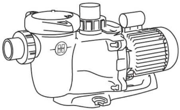
natural_image
Line drawing of an electric motor with cooling fins and housing (no text or symbols)
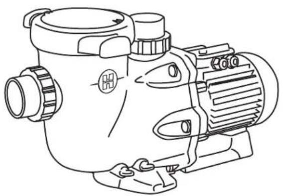
BOMBA CENTRÍFUGA
MANUAL DEL USUARIO
CONSERVE ESTE MANUAL PARA CONSULTARLO POSTERIORMENTE

HAYWARD®


natural_image
Abstract geometric logo with stylized letter H inside a circular frame (no text or symbols)HAYWARD®
natural_image
Line drawing of a mechanical pump or motor assembly (no text or symbols)
natural_image
Line drawing of a mechanical pump or motor assembly (no text or symbols)
BOMBA CENTRÍFUGA
MANUAL DO UTILIZADOR
CONSERVE ESTE MANUAL PARA REFERÊNCIA FUTURA

HAYWARD®


natural_image
Abstract geometric logo with stylized letter H inside a circular frame (no text or symbols)HAYWARD®
natural_image
Line drawing of a mechanical pump or motor assembly (no text or symbols)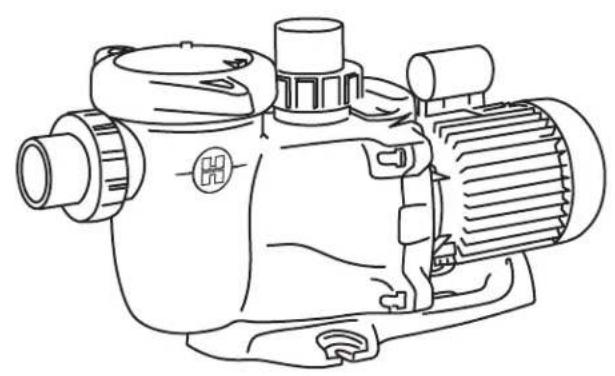
natural_image
Line drawing of a mechanical pump or motor assembly (no text or symbols)
ZENTRIFUGALPUMPE
ANWENDER - HANDBUCH
natural_image
Abstract geometric logo with stylized letter H inside a circular frame (no text or symbols)HAYWARD®

natural_image
Line drawing of a mechanical pump or motor assembly (no text or symbols)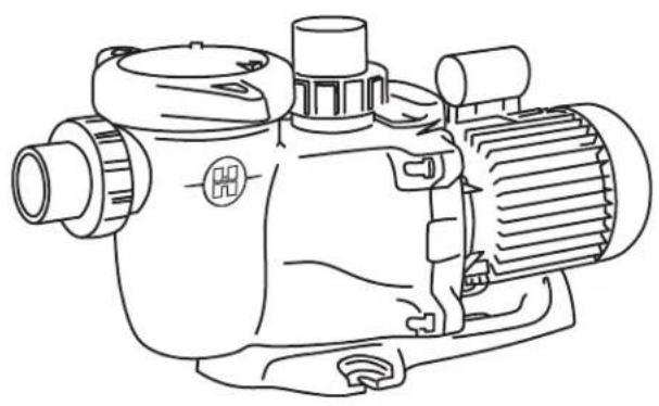
natural_image
Line drawing of an electric motor with cooling fins and housing (no text or symbols)
CENTRIFUGAALPOMP
GEBRUIKERSHANDBOEK
DIT HANDBOEK BEWAREN VOOR TOEKOMSTIG GEBRUIK

natural_image
Abstract geometric logo with stylized letter H inside a circular frame (no text or symbols)HAYWARD®
natural_image
Line drawing of a mechanical pump or motor assembly (no text or symbols)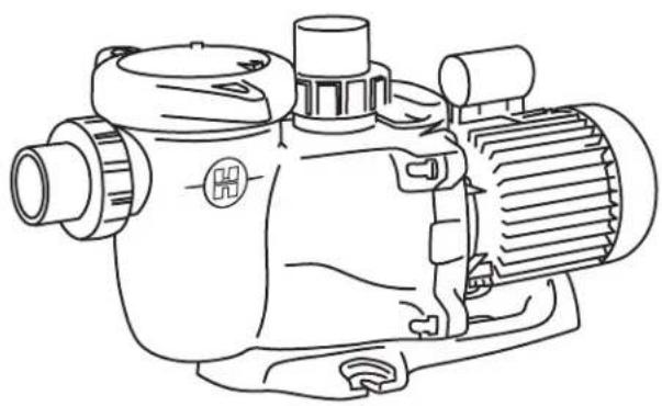
natural_image
Line drawing of an electric motor with cooling fins and housing (no text or symbols)
POMPA CENTRIFUGA
MANUALE PER L'USO
natural_image
Abstract geometric logo with stylized letter H inside a circular frame (no text or symbols)HAYWARD®
natural_image
Line drawing of a mechanical pump or motor assembly (no text or symbols)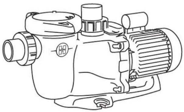
natural_image
Line drawing of a mechanical pump or motor assembly (no text or symbols)
CENTRIFUGALPUMP
ANVÄNDARHANDBOK
SPARA DENNA HANDBOK FÖR SENARE REFERENS
natural_image
Abstract geometric logo with stylized letter H inside a circular frame (no text or symbols)HAYWARD®
natural_image
Line drawing of a mechanical pump or motor assembly (no text or symbols)
natural_image
Line drawing of a mechanical pump or motor assembly (no text or symbols)
ЦЕНТРОБЕЖНЫЙ НАСОС
185 INCH LBS / 20.9 N m
TriStar
Max Flo XL
SP3200 SERIE: Tristar
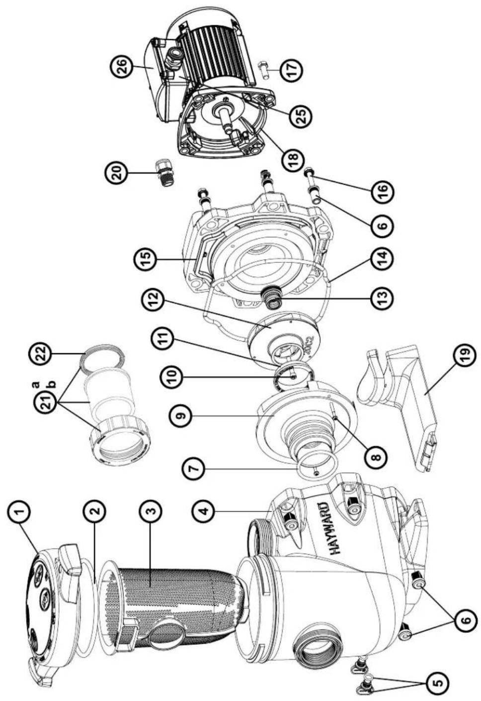
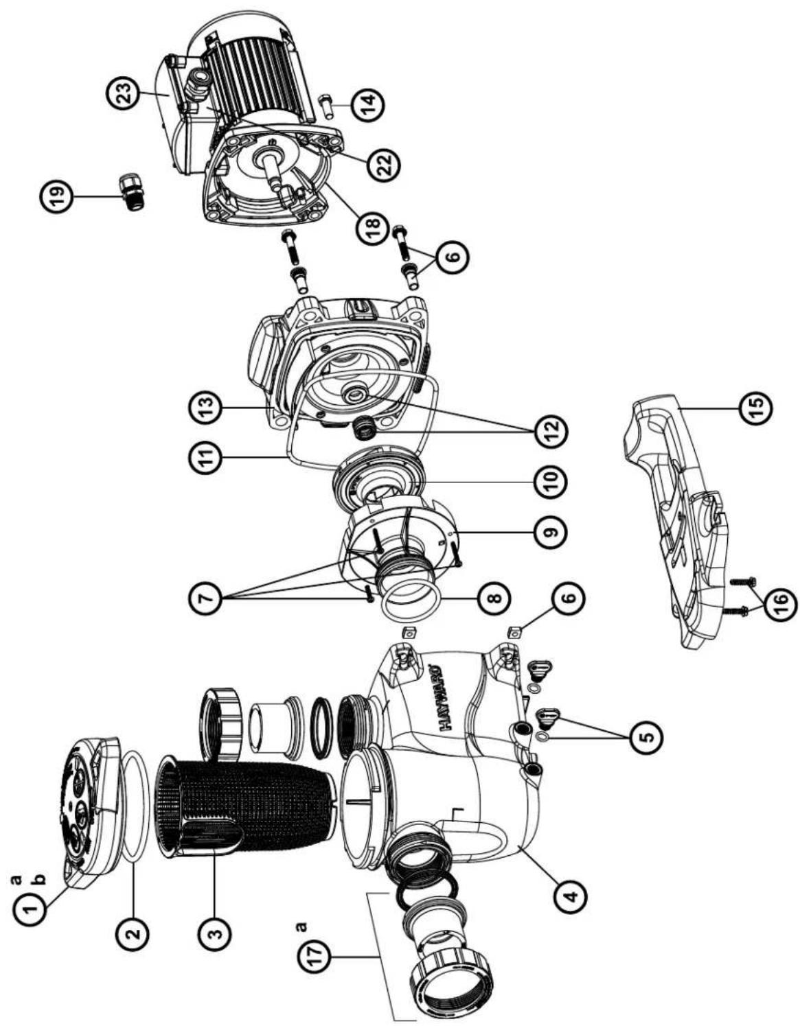
| No | Description / Description / Bezeichnung / Descripción / Descrizione / Beschrijving / Descrição / Beskrivning / Oписание |
| 1 | Strainer cover • Couvercle de préfiltre • Deckel • Tapa de prefiltro • Coperchio prefiltro • Zeef dekking • Tampa do filtro • Silskydd • Крышка ефильтра |
| 2 | Strainer cover O-Ring • Joint torique de préfiltre • O-Ring • Junta tórica • Guarnizione O'ring • De O-ring van de zeefdekking • Junta tórica da tampado filtro • Silskydd O-ring • Уплотнительное кольцо |
| 3 | Strainer basket • Panier de préfiltre • Filterkorb • Cesto filtrante • Cestino prefiltro • Zeef mand • Cesta do filtro • Silkorg • Корзина префильтра |
| 4 | Pump Housing/Strainer • Corps de pompe et préfiltre • Pumpengehäuse/Vorfilter • Cuerpo bomba y prefiltro • Corpo pompa/Prefiltro • Lichaam van pomp en préfiltre • Corpo de bomba e préfiltre • Pumphus/sil • Kopnyc насоса |
| 5 | Drain Plug • Bouchon de vidange • Ablasschraube • Tapón de vaciado • Tappo di spurgo • Afvoerkanaal stop • Plugue de dreno • Avtappningsplugg • Сливная пробка |
| 6 | Housing insert & seal plate spacer kit • Inserts de corps • KörperEinlagen • Partes de cuerpo • Inserzioni di corpo • Inserts van lichamen • Inserts decorpos • Husinsats & tätningsplatta distanssats • Втулка |
| 7 | Diffuser gasket • Joint de diffuseur • Dichtung • Junta de difusor • Guarnizione diffusore • Verbindingsstuk van verspreider • Junta de difusor • Diffusorpackning • Прокладка |
| 8 | Disffuser screws (x2) • Vis de diffuseur (x2) • Zerstäuberschraube (x2) • Tornillo de difusor (x2) • Vite di diffusore (x2) • Schroef van verspreider (x2) •Tornillos do difusor (x2) • spridare skruvar (x2) • Комплект винтов (x2) |
| 9 | Diffuser • Diffuseur • Leitapparat • Difusor • Diffusore • Verspreide • Difusor • Diffusor • Диффузор |
| 10 | Impeller screw • Vis de turbine • Turbinenschraube • Tornillo de turbina • Vite di turbina • Schroef van turbine • Tornillos de turbina • Impellerskruv •Комплект винтов |
| 11 | Ring for impeller • Bague pour turbine • Ring für Laufrad • Anillo para turbina • Anello • Ring voor Turbine • Ring de turbina • Уплотнительное кольцо |
| 12 | Impeller • Turbine • Laufrad • Turbina • Girante • Turbine • Turbina • Ring för pumphjul • Крыльчатка |
| 13 | Shaft Seal assembly • Obturateur mécanique • Motorhalterung • Cierre mecánico • Tenuta meccanica • Verbindings assemblage • Conjunto de selo •Impeller • Сальник в сборе |
| 14 | Housing gasket • Joint de corps • Dichtung • Junta • Guarnizione corpo • Huisvestings pakking • Gaxeta da carcaça • Axeltätningsenhet • Прокладка |
| 15 | Seal plate • Plateau d'étanchéité • Flansch • Plato de cierre • Supporto di fissaggio • Verbindings plaat • Placa do selo • Huspackning • Фланец |
| 16 | Housing bolt • Vis corps de pompe • Sechskantschraube • Tornillo cabeza exagonal • Viti a testa esagonale • Huisvestings GLB schroeven • Tornillosde tampão da carcaça • Tätningsplatta • Tätningsplatta • Комплект болтов |
| 17 | Motor bolt • Vis moteur • Sechskrantschraube • Tornillo • Viti • Schroef motor • Tornillos a motor • Motorbult • Husbult • Комплект болтов |
| 18 | Motor • Moteur • Motor • Motor • Motore • Motor • Motor • Motor • Электродвигатель |
| 19 | Bracket motor support • Support de pompe • Sockelteil • Soporte bomba • Supporto pompa • Opzettende steun • Suporte de montagem • Fästemotorstöd • Фланец электродвигателя |
| 20 | Gland • Presse étoupe • Kabel-Klemme • Prensa estopas • Pressacavo • Klier • Imprensa estopa • Körtel • Сальник |
| 21a | Union connector kit 50 mm • Kit de raccord union 50 mm • Anschluß-Stecker 50 mm • Asamblea del conectador de la unión 50 mm • Assemblea delconnettore del sindacato 50 mm • de assemblage van de unieschakelaar 50 mm • Conjunto do conector da união 50 mm • Kopplingssats 50 mm •Фитинг 50 мм |
| 21b | Union connector kit 63 mm • Kit de raccord union 63 mm • Anschluß-Stecker 63 mm • Asamblea del conectador de la unión 63 mm • Assemblea delconnettore del sindacato 63 mm • de assemblage van de unieschakelaar 63 mm • Conjunto do conector da união 63 mm • Kopplingssats 63 mm •Фитинг 63 мм |
| 21c | Fitting pack 2" USA Imperial • Pack Raccord 2" USA Imperial • Passende Packung 2" USA Imperial • Paquete de unión 2" USA Imperial • PacchettoUnion 2" USA Imperial • Montagepakket 2" USA Imperial • 2" pacote de união USA Imperial • Fitting pack 2" USA Imperial • Комплект фитингов 2" |
| 22 | Union gasket • Joint pour raccord union • O-Ring • Junta tórica • Guarnizione O'ring • O'ring Dichtheidsadepter • Junta tórica de adaptador •Unionspackning • Прокладка |
| 2+713+14 | Set of gaskets • Pack de joints • Satz Dichtungen • Juego de juntas • Set di guarnizioni • Set van pakkingen • Conjunto de juntas • Uppsättningpackningar • Комплект прокладок |
| - | Capacitor • Condensateur • Kondensator • Condensator • Condensatore • Capacitor • Condensator • Kondensator • Конденсатор |
| - | Fan • Ventilateur • Fan • Ventilador • Fan • Ventilador • Fan • Fläkt • вентилятор |
| - | Fan cover • Capot ventilateur • Lüfterhaube • Cubierta del ventilador • Copriventola • Fan cobertura • Ventilatordeksel • Fläktkápa • Кожухвентилятора |
| - | Motor Bearings Kit • Kit Roulements moteur • Motorlager-Kit • Kit de rodamientos de motor • Kit cuscinetto del motore • Motorlagers kit • Kitrolamentos do motor • Motorlagersats • Подшипники двигателя комплект |
| 25 | Junction box • Boîte de connexion • Anschlubdose • Caja de conexión • Scatola di giunzione • Kverdeeldoos • Caixa de Ligaçao • Kopplingsdosa •Распаечная коробка |
| 26 | Cover • Couvercle • Deckel • Tapa • Coperchio • Deksel • Tampa • Omslag • Крышка |
| - | Slinger • Larmier • Tropfing • Arandela Separación • Rondella di separazione • Tropfing • Arandela Separación • Slinger • Маслосьемное кольцо |
SP2300 SERIE: MAX-FLO XL
WARRANTY CONDITIONS AND EXCLUSIONS FOR EU COUNTRIES
Our consumer products in the European Union, which are intended to be sold to consumers and users, have a warranty in accordance with the relevant consumer protection regulations. All HAYWARD ^® products are covered for manufacturing defects or material defects for a warranty period of 3 years as of date of purchases. Any warranty claim should be accompanied by evidence of purchase, indicating date of purchase. We would therefore advise you to keep your invoice.
The HAYWARD ^® warranty is limited to repair or replacement, as chosen by HAYWARD ^® , of the faulty products, provided that they have been subjected to normal use, in compliance with the guidelines given in their user guides, provided that the products have not been altered in any way, and provided that they have been used exclusively with HAYWARD ^® parts and components. The warranty does not cover damage due to frost and to chemicals. Any other costs (transport, labour, etc.) are excluded from the warranty.
HAYWARD ^® may not be held liable for any direct or indirect damage resulting from incorrect installation, incorrect connection, or incorrect operation of a product.
In order to claim on a warranty and in order to request repair or replacement of an article, please ask your dealer.
No equipment returned to our factory will be accepted without our prior written approval.
Wearing parts are not covered by the warranty (see maintenance part of the manual).
Provision on waste electrical and electronic equipment from professionals. In accordance with Directive 2012/19/EU on the management of waste electrical and electronic equipment, this pump must be taken to a separate collection point. ==> Contact your distributor for more information.
SE - MILJÖINFORMATION:
- HAYWARD®
- POMPE CENTRIFUGE
- WARNING: Electrical Hazard. Failure to follow instructions can result in serious injury or death. FOR USE WITH SWIMMING POOLS
- GENERAL POINTS
- Necessary measures:
- Single phase electric motor:
- Three phase electric motor:
- INSTALLATION
- MAINTENANCE
- WINTERING
- TROUBLESHOOTING
- A) The motor does not start
- B) The motor stops, check
- D) The pump does not prime
- E) Low flow - Generally, Check for :
- BOMBA CENTRÍFUGA
- ZENTRIFUGALPUMPE
- CENTRIFUGAALPOMP
- POMPA CENTRIFUGA
- WARRANTY CONDITIONS AND EXCLUSIONS FOR EU COUNTRIES
- SE - MILJÖINFORMATION:
Brand : HAYWARD
Model : TriStar
Category : Pump