
AquaRite Neo pH - Water pump HAYWARD - Free user manual and instructions
Find the device manual for free AquaRite Neo pH HAYWARD in PDF.
| Product type | Pool chlorinator with automatic pH regulation |
| Brand and model | Hayward AquaRite Neo pH |
| Power supply | 230 V AC, 50/60 Hz |
| Maximum power consumption | 65 W to 150 W depending on model (AQR-NEOPH-08: 65 W, AQR-NEOPH-16: 120 W, AQR-NEOPH-22: 130 W, AQR-NEOPH-33: 150 W, AQR-NEOPH-50: 120 W) |
| Chlorine production (max) | 8 g/h to 50 g/h depending on model |
| Recommended salt range | 1.5 g/L to 3 g/L depending on model (Low Salinity: 1.5 g/L) |
| pH regulation | Integrated, with pH probe, peristaltic dosing pump and adjustable set point |
| Available options | Redox probe (Rx), temperature probe, WiFi module, Ethernet module |
| Display | Digital screen with menus and alarms |
| Safety detection | Mechanical flow detector, gas detector in the cell |
| Installation type | Wall-mounted, vertical, in a dry and ventilated technical room |
| Minimum distance from pool | 3.5 meters (or according to local regulations) |
| Electrical protection | 16 A time-delay circuit breaker recommended, protected outlet with 30 mA RCD |
| Common wear parts | Titanium cell (8000 h), pH probe (1 year), Santoprene pump tube (2 years), seal (2 years) |
| Regular maintenance | Cell cleaning if scaling, pH probe calibration every 2 months, salt level check |
| Warranty | 3 years (parts and labor), excluding wear parts and damage due to frost or chemicals |
| Weight (approx.) | Approximately 5 kg (unit with cell) |
| Dimensions (L x H x D, approx.) | 35 cm x 35 cm x 15 cm (unit) |
| Compliance standards | Low Voltage Directive 2014/35/EU, EMC 2014/30/EU, RoHS, IPX4 |
| Environmental information | WEEE: selective collection at end of life, integrated CR2032 battery to be removed |
Frequently Asked Questions - AquaRite Neo pH HAYWARD
User questions about AquaRite Neo pH HAYWARD
0 question about this device. Answer the ones you know or ask your own.
Ask a new question about this device
Download the instructions for your Water pump in PDF format for free! Find your manual AquaRite Neo pH - HAYWARD and take your electronic device back in hand. On this page are published all the documents necessary for the use of your device. AquaRite Neo pH by HAYWARD.
USER MANUAL AquaRite Neo pH HAYWARD
natural_image
Abstract geometric logo with stylized letter H inside a dark circular frame (no text or symbols)HAYWARD®
natural_image
Exterior view of a modern air conditioner unit with digital display and control buttons (no visible text or symbols)® Neo
natural_image
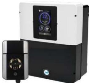
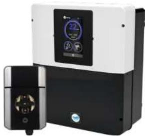
Exterior view of two industrial water treatment devices with digital displays (no visible text or symbols)AquaRite ^® Neo pHAqua
CE EAC UK CA

natural_image
Two simple line drawings: an open book icon with an information symbol, and an open book with a closed section (no text or symbols)GUIDE DE L'UTILISATEUR OWNER'S MANUAL MANUAL DEL USUARIO MANUAL DO UTILIZADOR ANWENDERHANDBUCH GEBRUIKERSHANDLEIDING MANUALE D'USO
ISAQRNEO Rev A 2025


HAYWARD®
natural_image
Exterior view of a modern industrial air conditioner unit (no visible text or symbols)AquaRite® Neo AquaRite
natural_image
Exterior view of a modern industrial air purifier unit with digital display and control panel (no visible text or symbols)Neo pH
CE EAC UK CA


GUIDE DE L'UTILISATEUR
CONSERVEZ CE MANUEL POUR UNE CONSULTATION ULTÉRIEURE
HAYWARD POOL EUROPE - 1070 Allée des Chênes - CS 20054 Saint Vulbas - 01154 Lagnieu Cedex - France
HAYWARD
HAYWARD


- CONDITIONS DE GARANTIE ET EXCLUSIONS
POUR LES PAYS DE L'UNION EUROPÉENNE 17
-
INFORMATIONS ENVIRONNEMENTALES
-
DÉCLARATION DE CONFORMITÉ
HAYWARD
1. DESCRIPTION DE L'APPAREIL
Kit solutions tampons
Porte Sonde
Presse étoupe
Bouchon 1/2"
Joint 1/2
* Neo AquaRile
3b. Installation murale
The quick brown fox jumps over the lazy dog.
nose: Heyard PaciWatch
natural_image
Exterior view of a modern industrial air conditioner unit with control panel (no visible text or symbols)AquaRite® Neo AquaRite
natural_image
Exterior view of a modern industrial air purifier unit with digital display and control panel (no visible text or symbols)Neo pH
CE EAC UK CA


AquaRite Neo
OWNER'S MANUAL
KEEP THIS GUIDE FOR FUTURE REFERENCE
* Neo
WARNING: Electrical hazard. Failure to comply with these instructions can result in serious injuries or death. THE EQUIPMENT IS INTENDED TO BE USED ONLY IN SWIMMING POOLS
⚠ WARNING – Carefully read the instructions that appear in this manual and on the device. Failure to comply with the instructions can cause injuries. This document must be given to every pool user, who should keep it in a safe place.
⚠ WARNING – Disconnect the equipment from the mains supply before any intervention.
⚠ WARNING – All electrical connections must be carried out by a qualified approved electrician in accordance with the standards currently in force in the country of installation or, failing this, in accordance with the international standard IEC 60334-7-702.
⚠ WARNING - Check that the device is plugged into a power outlet that is protected against short-circuits. The device must also be powered via an isolating transformer or a residual current device (RCD) with a nominal operating residual current not exceeding 30 mA.
⚠ WARNING – Ensure that children cannot play with the device. Keep your hands and any foreign object away from openings and moving parts.
⚠ WARNING – Check that the supply voltage required by the product corresponds to the voltage of the distribution network and that the power supply cables are suitable for the product power supply.
⚠ WARNING – Chemicals can cause internal and external burns. To avoid death, serious injury and/or damage to equipment, wear personal protective equipment (gloves, goggles, mask, etc.) when servicing or maintaining this device. This device must be installed in an adequately ventilated place.
⚠ WARNING – The unit must not be operated when there is no water flow in the cell.
⚠ WARNING – The cell must be located in a well ventilated environment so hazardous accumulation of hydrogen gas does not occur.
⚠ WARNING – To reduce the risk of electric shock, do not use an extension cable to connect the device to the mains. Use a wall socket.
△ WARNING - Use, cleaning or maintenance of the device by children over 8 years of age or by people with impaired physical, sensory or mental capacities, or a lack of experience or expertise, should only take place once they have received appropriate instruction and under adequate supervision of an adult who is responsible for them, to ensure the device is handled safely and avoid all risk of danger. This device must be kept out of reach of children.
⚠ WARNING – Use only original Hayward® parts.
⚠ WARNING – If the power supply cable is damaged, it must be replaced by the manufacturer, the after-sales service or similarly qualified persons to avoid danger.
⚠ WARNING – The device must not be used if the power cord is damaged. An electric shock could occur. A damaged power cord must be replaced by the after-sales service or similarly qualified persons to avoid danger.
* Neo AquaRile
Page 2 on 18 Page 3 on 18AquaRite
Only use spare parts supplied by Hayward brands

IAYWARD
- DESCRIPTION OF THE DEVICE 4
- PACK CONTENTS 4
- INSTALLING THE DEVICE 5
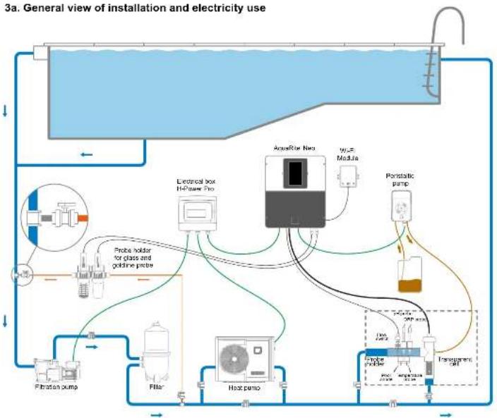
3a. General view of installation and electricity use 5
3b. Installation on a wall 6
3c. Connecting the electronic circuit board 6
3d. Cabling the box 7
3e. Installing the cell and the mechanical flow switch 8 - OPERATION OF THE DEVICE 9
4a. View and description of the home screen 9
4b. Electrolysis / hydrolysis menu 9
4c. Configuring the box 10 - CONNECTING AND CONFIGURING THE OPTIONS 11
5a. Installation and start-up of the pH option 11
5b. Installation and start-up of the Rx (ORP) option 12
5c. Installation and start-up of the temperature option 13
5d. Installation and start-up of the WIFI module 14 - DESCRIPTION OF MESSAGES / ALARMS 15
- CHEMICAL WATER BALANCE 15
- TROUBLESHOOTING GUIDE 16
- APPENDICES 16
9a. Configuring the cell safety feature 16 - WARRANTY CONDITIONS
AND EXCLUSIONS FOR EUROPEAN UNION COUNTRIES 17 - ENVIRONMENTAL INFORMATION 17
- DECLARATION OF CONFORMITY 17
* Neo
Only use spare parts supplied by Hayward brands*

HAYWARD
1. DESCRIPTION OF THE DEVICE

Control system:
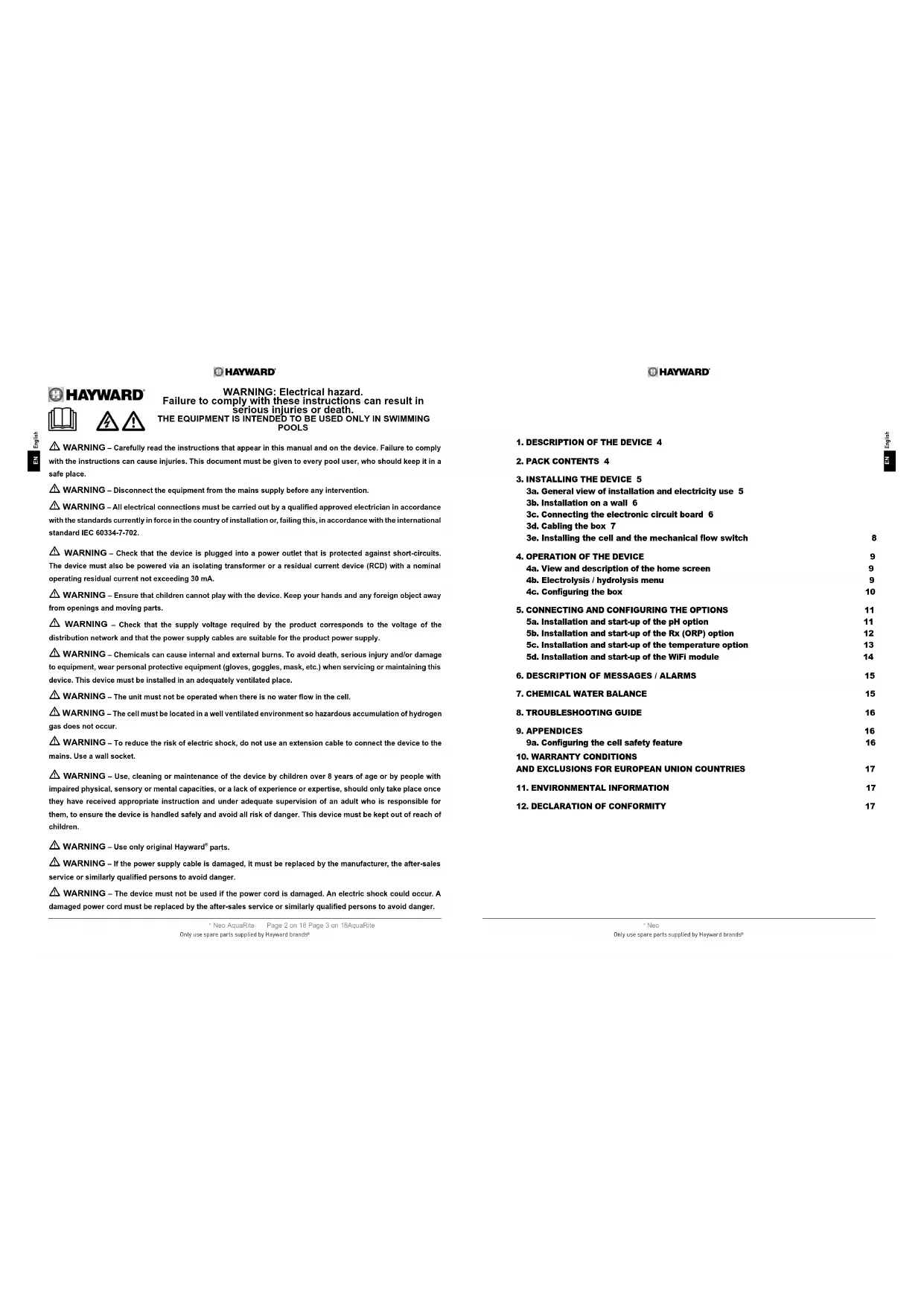
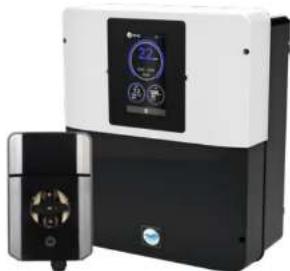
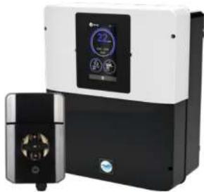
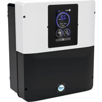
The pool salt chlorinator AquaRite® Neo (LS included) is a chemical water treatment system, water disinfection system, and automatic pH regulator. Remote management is possible using the WiFi or Ethernet options.
Water treatment:
AquaRite® Neo: Chlorine is produced by electrolysis of water at a low salt concentration. The electrolysis cell produces sodium hypochlorite (liquid chlorine) starting at 3g of salt per litre. The chlorine combats and eliminates the bacteria, viruses and pathogenic agents, and oxidises the organic matter present in the water. The sodium hypochlorite used recombines into salt after a few hours.
AquaRite ^® Neo Low Salinity: It is an effective water treatment method for your pool that uses electrolysis and hydrolysis of salt water. To operate, the salt chlorinator requires a very low concentration of salt (1.5 g salt per litre) in the pool water. The cell produces sodium hypochlorite (liquid chlorine) and free radicals with more powerful disinfection capabilities than sodium hypochlorite. The chlorine and the free radicals combat and eliminate the bacteria, viruses and pathogenic agents, and oxidises the organic matter present in the water. The sodium hypochlorite used recombines into salt after a few hours.
The quantity of aerobic required to treat a pool correctly varies depending on the number of swimmers, the number of hours of filtration, precipitation levels, the water temperature, and the water cleanliness and maintenance of its chemical balance.
Before installing this product on the filtration system of a pool or of a spin with an adjacent clock or clock made up of radial stones, except a qualified controller, who will continue you about the type. Installation, underweight (if required) and maintenance of the stones placed around a pool containing salt.
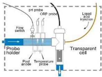
① Chlorine production (g/h or %), claims, the measured pH. Fix and temperature values are visible and updated on the screen.
12 inch flow switch

Electrolysis cell

Transparent mount for probe and flow switch and 4 ½ inch plugs.
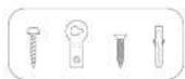
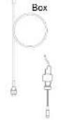
2. PACK CONTENTS
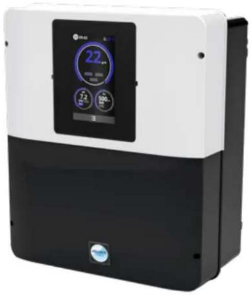
Peristaltic pump
pH Chip
able gland
1/2" plug
1/2" seal
Holder mount
obe holder
Buffer solutions kit

Drilling template

Owner's Manual
accessible via QR code


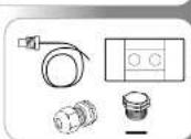
Temperature probe
Probe holder
Cable gland
1/2" plug
1/2" seal
* Neo AquaRile
Page 4 on 18 Page 5 on 18AquaRite
Only use spare parts supplied by Heyward brands
HAYWARD
3. INSTALLING THE DEVICE
flowchart
graph TD
    A["Electricity System"] --> B["Refrigerator"]
    B --> C["Pressure Gauge"]
    B --> D["Flow Meter"]
    B --> E["Sensor"]
    B --> F["Pressure Pump"]
    B --> G["Heat Pump"]
    B --> H["Pressure Filter"]
    B --> I["Filtration Pump"]
    B --> J["Electrical box Refuser Pro"]
    B --> K["AqueRise Net"]
    B --> L["Micro Module"]
    B --> M["Peristatic pump"]
    B --> N["Probe holder for glass and goldine probe"]
    B --> O["Probe holder for glass and goldine probe"]
Maximum consumption and generation
△ Use of a 16 A time-delay circuit breaker is recommended for the box.
| Product Maximum consumption g C/h | ||
| AQR-NEOPH-08 65W 8 | ||
| AQR-NEO-16 / AQR-NEOPH-16 120W 18 | ||
| AQR-NEO-22 / AQR-NEOPH-22 130W 22 | ||
| AQR-NEO-33 / AQR-NEOPH-33 150W 33 | ||
| AQR-NEO-50 / AQR-NEOPH-50 150W 50 | ||
| AQR-NEO-11.5 | 120W | Equiv 15 |
| AQR-NEO-2LS | 150W | Equiv 30 |
| AQR-NEO-3LS | 150W | Equiv 45 |
Neo
Only use spare parts supplied by Hayward brands*

HAYWARD
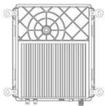
3b. Installation on a wall
- Without opening the lid, screw the 4 keyhole hangers to the back of the box.
- Locate the position of the 4 keyhole hangers using the drilling template.
- Drill 4 holes in the wall and insert the 4 anchors into them.
- Screw the 4 mounting screws to the wall and hang the device vertically with the cell connector positioned at the bottom.
The box must be installed in the plant room (dry, temperate conditions, ventilated). Take care, acidic vapour can irreversibly damage your device. Take this into account in the positioning of the treatment product storage containers. Unplug the pool filter pump before you begin the installation. The installation must be performed in compliance with the regulations in effect in the country of installation. The box must be installed at a minimum horizontal distance of 3.5 metres (or more, if local legislation requires it) from the pool, at less than 1 metre from a protected socket, and at less than 4.5 metres from the planned position of the cell. The box must be installed vertically, on a flat surface, with the cables orientaled downwards. Given that the box is also used for evacuating heat (heat dissipation from the internal components), it is important for space to be left around the four sides of the box. Don't mount the box behind a partition wall or in a closed environment. Before you fix the control box in place in the planned position, check that the power supply cord reaches the protected socket and that the cell cable reaches the planned cell installation position. All metal pool components can be connected to the same earth in accordance with local regulations.

natural_image
Technical line drawing of a heat exchanger or cooling unit with fan and vent (no text or symbols)3c. Connecting the electronic circuit board
Remove the black lid by
unscrewing the
4 screws using a
screwdriver.
△ Connect the sensors with great care.
A bad connection may irreparably damage the device.
Neo AquaRile
Page 6 on 18 Page 7 on 18AquaRite
Only use spare parts supplied by Hayward brands
HAYWARD
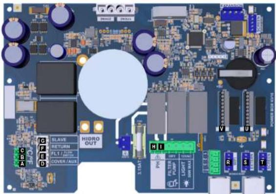
Connection of inputs:
| Board Label Description Terminals Input / output type | ||||
| Main | PC | Temperature probe | A-B-C | Red, yellow, black |
| Main | COVER / AUX | Closed shutter defector | D-F | Dry contact |
| Main | FL1 / FLOW SWITCH | Mechanical flow switch | E-F | Unpowered dry contact |
| Main | SLAVE | Terminal for master or slave unit | G-F | Dry contact |
| Main | PH | Perisatilic or electromagnetic closing pump | H-I | Output voltage 230 VAC 5 A max |
| Main SCREEN | Remote screen (option) | R | Modbus RS465 From top to bottom and free yellow/green block | |
| Main | WiFi | WiFi or Ethernet module (as an option) | S | Modbus RS465 From top to bottom and free yellow/green block |
| Main | EXTERN | Standard communication connector | T | Modbus RS465 From top to bottom and free yellow/green block |
| Main | PH | pH chip connection, annotation and LED on the left | U | 5 VDC |
| Main | RX | FX chip (option) connection, annotation and LED on the left | V | 5 VDC |
3d. Cabling the box
*Neo
Only use spare parts supplied by Hayward brands*

HAYWARD
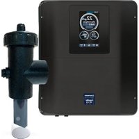
3e. Installing the cell and the mechanical flow switch

△
The installation has 2 safety features: the mechanical flow switch and the gas detector in the cell.
i
If the device is being installed with 50 mm diameter pipework, please consult the spare parts sheet for the slip adaptor fittings.

Installing and connecting the cell (see diagram):
• Install the cell mount vertically (if it is installed horizontally, please read the technical information sheet appendices to correctly adapt the box programming).
• Install the cell in a bypass.
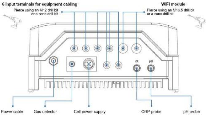
- Connect the power supply cable underneath the box using the 4-pin socket, and the gas detector to the RCA socket.
Installing and connecting the mechanical flow switch:
• Install the flow switch mount before the cell and on the bypass.
- Screw the flow switch onto the 14 " male thread.
- Connect the red and black cables to the electronic circuit board terminals Ⓤ and Ⓔ
HAYWARD
The device is designed to be permanently plugged in to a protected socket. The AquaRite Neo must not be unplugged except to carry out pool equipment maintenance or if the pool must be closed (wintering).
When the water parameters are within the recommended ranges, you can start up the device.
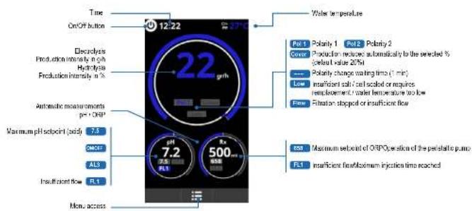
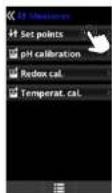
4a. View and description of the home screen
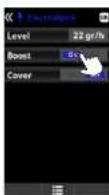
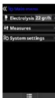
4b. Electrolysis / hydrolysis menu
△ Chlorine production depends on the gas detector and the mechanical flow switch.
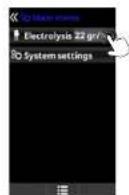
Electrolysis / Hydrolysis: Programming of electrolysis/ hydrolysis functions.
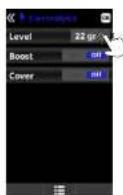
Level
Production of chlorine (g/m) desired for electrolysis
Production of chlorine (%) desired for hydrolysis.
Shock treatment: Continuous filtration for 24 hours at maximum intensity. Automatic return to the programmed filtration mode. During the shock treatment, ORP control can be deactivated.
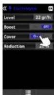
Cover:
Recruence in % chlorine
production when the cover
is closed.
When the cover is closed,
I do not necessary for the
electrolysis to operate
at 100%. Adjust the %
reduction in chlorine
production.
Neo AquaRile
Page 6 on 18 Page 9 on 18AquaRite
Only use spare parts supplied by Hayward brands
* Neo
Only use spare parts supplied by Hayward brands*


HAYWARD
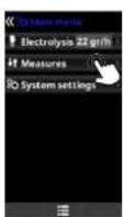
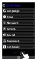
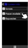
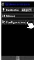
4c. Configuring the box


Language: setting of the preferred language. Data and time: setting of the day and time. Screen: adjustment of screen brightness (0-100%); programming of screen on/off times and of display of the main screen.


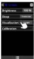


Time Info: the system registers the secret hours of operation of the cell and displays the value on this screen. The number in baseball corresponds to the number of counter results. System Info: information about the available software version of the TFT screen and the power module. The node ID required for configuration of the system WiFi connection is also indicated.
Neo AquaRile
Page 10 on 16 Page 11 on 18AquaRite
Only use spare parts supplied by Hayward brands
HAYWARD
5. CONNECTING AND CONFIGURING THE OPTIONS
5a. Installation and start-up of the pH option
- Open the lid, and connect the pH CHIP card to the PH slot (see section 3C).
Connect the dosing pump to the pH terminal using a cable gland (see sections 3C and 3D) and close the lid.
Install the probe and its mount in the pipework, and connect the probe to the box (see section 3D). - Follow the pH kit instructions to inject liquid.
- Tum the box off and on using the switch.
The Measures menu appears automatically to enable the setpoint to be configured and to perform the calibration.

The lifetime of the probable 1 year. We recommend that you change it every year.
Operation of the liquid pH dosing pump:
- The pump starts up according to the setpoint set in the Measures - Setpoints - pH acid menu (setpoint < pH of water).
- By default, the maximum dosing time is 120 mins to avoid acidification of the water (AL3).
- A proportional injection method is used: 10 minutes ON (variable as a function of the difference between the value measured and the setpoint) + 5 minutes OFF (fixed).
• A change of dosing mode from acid to alkali is possible (contact your installer).
• The pump is equipped with a stop/start switch.
The Bartoprene tube of the peristallic pump has a lifetime of 2 years.
We recommend that you change it once a year.
① We recommend injection of sulphuric acid to avoid confection and pose
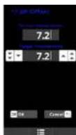
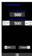
Configuring the pH setpoint:
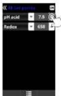
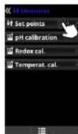
Measure:
Adjustment of asipants
Setpoints
Setpoints for each of the measurements.
Determination of setpoints:
Comparison of the English text in Chinese. The default value is 7.2.
* Neo
Only use spare parts supplied by Hayward brands*


HAYWARD
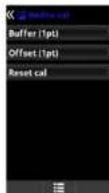
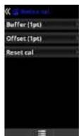
Calibrating the pH probe:
△ Always begin the calibration procedure with a calibration reset.
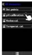

pH calibration:
Calibration of the oil probe; recommended every 2 months during the session the pool is in use.
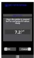
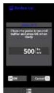
Buffer:
Calibration using buffer solutions (pH7 / pH10 / neutral buffer solutions); follow the 7-seep instructions which appear on the screen (the Step 1/7 screen corresponds to step 1). Reset call:
The Reset Cal option deletes all calibrations performed previously.

C/ffwd:
Manual calibration: with this method the probes can be calibrated using 1 point (no buffer solution) - recommended only in the case of small measurement differences.
Without remaining the probe from 5-water, adjust the measure displayed using the plasiminus buttons so that it concludes with the reference value (photometry or other measurement device).
5b. Installation and start-up of the Rx (ORP) option
- Open the lid, and connect the RX CHIP card to the Rx slot (see section 3C).
Install the probe and its mount in the pipework, and connect the probe to the box (see section 3D) and close the lid.
- Turn the box off and on using the switch.
- The Measures menu appears automatically to enable the setpoint to be configured and to perform the calibration.
The lifetime of the proof is 1 year. We recommend that you change it every year.
Operation of the ORP module:
- When the redox (ORP) option is connected, the electrolysis cell starts up whenever the measured redox value drops below the setpoint.
Configuring the rX setpoint:
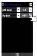
Measures:
Adjustment of selpoints.
Setprints
Sequoia 34 mars of the mislabeling
Determination of setpoints: Configuration of the deal levels for each parameter
The default sepcert value is 700 mV.
Neo AquaRile
Page 12 on 16 Page 13 on 18AquaRite
Only use spare parts supplied by Heyward brands
HAYWARD
Calibrating the Rx (ORP) probe:
△ Always begin the calibration procedure with a calibration reset.


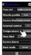
5c. Installation and start-up of the temperature option
- Open the lid and connect the temperature probe using a cable gland (see sections 3C and 3D) and close the lid.
Configure the temperature probe in the box.
The value of the temperature appears at the top right of the screen.
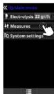
Configuring the temperature probe in the box:
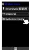
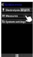
Go to System settings

Go to Service Menu
and pink OK

Enter the password:
Counsel your existing

Go to Extra Settings and
ринки ОК
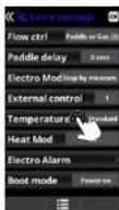
Go to the Temperature.
men, select Standard
the selection
Neo
Only use spare parts supplied by Hayward brands*


HAYWARD
5d. Installation and start-up of the WiFi module
- Open the lid and pierce the box with a 16.5 drill bit (see section 3D).
③ Pass the WiFi cable connector through this, position the cable gland. - Connect the white WiFi connector to the WiFi slot (see section 3C) and close the lid.
The Network menu appears automatically in the System settings menu. - Configure the WiFi connection in the box and on your telephone or on the website.
Check that the 2 LEDs of the WiFi module are continuously on before connecting via the app or the website.


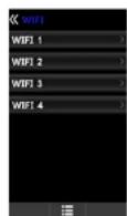
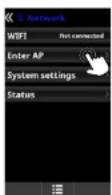

WIFI:
Select WIFI to scan the networks within reach of the module. The search is done automatically. Select the desired networks that is within reach of the WIFI much in
Enter the password for this activity when he posted. To confirm, please 5%
2.1.1.3
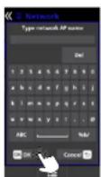
Enter AP:
If the network is not found automatically, mostly either the counts and the responses of the desired network.
If the network is first, it can be necessary. Military order the home and the purpose of this course is required.
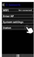
System settings:
If you want to configure the settings in more detail. By default, leave DECP = ON.
Status:
Verify the status of your connection. Display the exchanges of data received from and sent to the servers.
Configuring the connection on your telephone and/or the website:


△ Once the module is connected to the WiFi network with the two LEDs continuously on (front), you can register yourself at photowatch byesee1.6 or on the spin byeawn/ Poolwatch.
Make sure you have your Node ID (in the power module menu) and follow the registration process. You can scan the QR code and copy/paste it into the registration form. Once you have registered, you can supervise and manage all the parameters in your box remotely with Hayward Post/Watch.
① The Hayward Fee/watch app is available on the App Store and Google Play and is free.

△ Only WiFi networks with a frequency of 2.4 GHz are accepted by the module
* Neo AquaRile
Page 14 on 16 Page 15 on 18AquaRite
Only use spare parts supplied by Hayward brands
HAYWARD
- DESCRIPTION OF MESSAGES / ALARMS
| P1/P2 | Cell operation polarity. The cell automatically reverses its polarity to perform self-cleaning. |
| COV | The cover detector indicates that the cover is closed. Production is automatically reduced to the value registered in the Electrolysis menu. |
| FL1/FLOW | Lack of flow through the installation. Check the mechanical flow switch and the gas detector and make sure the pressure is correct. · Check the mechanical flow switch and the gas detector. · Check that the filtration pump works. · Check that nothing is obscuring the pipes (valve is closed, strainer or prefilter are full, etc.). · Check that the 4A fuse is not faulty. |
| LOW | The device is not reaching the desired level of production. This may be due to several factors: · a lack of salt · scaled coil · exhausted cell (check the line counter) · low water temperature |
| AL3 | The maximum allowable time for the pH setpoint to be reached has ended. The acid pH dosing pump has been stopped to avoid excess dosage and acidification of the water. Make the following checks: · Check that the liquid pH container is not empty. · Check that the pH value read on the machine corresponds to the pH of the pool (use a pH analysis kit). If this is not the case, calibrate the pH probe or change it, if necessary. · Check that the pH pump is operating normally. · Check the correction time selling. To make this message disappear and re-start the dosing, press and hold "back" for 3 seconds. |
7. CHEMICAL WATER BALANCE
The water must be balanced manually BEFORE the device is started up.
The following table summarizes the concentrations recommended by Hayward. Your water should be checked regularly to maintain these concentrations and minimize surface corrosion or deterioration.
| Chemistry Recommended concentrations | |
| Salt 3 g/t 1.5 g/L for low elderly males | |
| Free daily life 6.5 to 2.5 ppm | |
| pH 7.2 to 7.6 | |
| Cysticate add (Roebuery) | 20 to 30 ppm max.(Add stabilizer only if necessary)6 ppm in indoor pool |
| Total eligibility 80 to 120 ppm | |
| Water hardness 200 to 300 ppm | |
| Votals 9 ppm | |
| Langelter index -0.2 to 0.2 (preferably 9) | |
*Neo
Only use spare parts supplied by Hayward brands ^4


| Cell operation polarity. The cell automatically reverses its polarity to perform self-cleaning. |
| The cover detector indicates that the cover is closed. Production is automatically reduced to the value registered in the Electrolysis menu. |
| Lack of flow through the installation. Check the mechanical flow switch and the gas detector and make sure the pressure is correct. - Check the mechanical flow switch and the gas detector. - Check that the titration pump works. - Check that nothing is obscuring the pipes (valve is closed, strainer or prefilter are full, etc.). - Check that the 4A fuse is not faulty. |
| The device is not reaching the desired level of production. This may be due to several factors. - a lock of salt. - scaled call. - exhausted cell (check the time counter) - low water temperature |
| The maximum allowable time for the pH setpoint to be reached has entered. The acid pH dosing pump has been topped to avoid excess dosage and acidification of the water. Make the following checks: - Check that the liquid pH container is not empty. - Check that the pH value read on the machine corresponds to the pH of the pool (use a pH analysis kit). If this is not the case, calibrate the pH probe or charge it, if necessary. - Check that the pH pump is operating normally. - Check the correction time setting. - I make this message disappear and re-start the dosing, press and hold "back" for 3 seconds. |

HAYWARD
8. TROUBLESHOOTING GUIDE
No display
Check the connection cable between the display and the control box.
Check that the 4A fuse is not defective (located inside the control box).
Check the power supply: 220-230 V, 50/60 Hz. If the problem persists, contact your pool installer/builder.
Excessive chlorine
Check and/or adjust the chlorine production setting. If your pool has an automatic ORP control system, check the ORP setting. Check the ORP probe and calibrate, if necessary.
Salt chlorination does not reach the required production rate
Check the concentration of salt in the water (depending on the model).
Check the condition of the cell (it may be dirty or covered in scale).
Clean the cell according to instructions.
Check the flow switch and clean if necessary. Check that the cell is not worn (contact your pool installer/builder).
Cell scaled up in under a month
Very hard water with high pH and total alkalinity (balance and adjust the pH and total alkalinity of the water). Check that the system automatically changes polarity (see display).
Impossible to attain a free chlorine level of 1 ppm
Increase the filtration time.
Increase the chlorine production rate of the electrolysis. Check the concentration of salt in the water (see table Chemical water balance).
Check the level of isocyanuric acid in the pool (see table Chemical water balance).
Check that the reactive agents in your test kit are not out of date.
Adjust the chlorine production according to the temperature and the number of pool users.
Adjust the pH to ensure that it is always below 7.8.
White flakes in the pool
This occurs when the water is unbalanced and very hard. Balance the water, check the cell and clean it, if necessary.
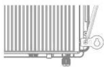
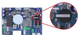
Changing the battery
Unscrew the cover using the 4 screws and locate the
battery (see image)
Change the battery (CR2032 type). Screw the cover back on using the 4 screws.
9. APPENDICES
9a. Configuring the cell safety feature
If the cell is installed horizontally, the cell on detector safety feature must be deactivated. Follow these steps:
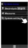
Go to System settings and press OK
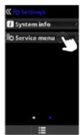
Go to Service Menu and press OK

Enter the password: Contact your installer
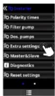
Go to Extra perm. and press OK.
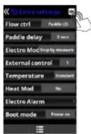
Go to the Flow ctrl menu and select Paddle (2). Press OK to confirm the selection. By default, the box is set to Paddle or gas (3).
* Neo AquaRite Page 16 on 18 Page 17 on 18AquaRite
Only use spare parts supplied by Hayward brands
HAYWARD
10. WARRANTY CONDITIONS
AND EXCLUSIONS FOR EUROPEAN UNION COUNTRIES
All HAYWARD ^2 products are covered for manufacturing defects or material defects for a warranty period of 3 years as of date of purchase. Proof of purchase, indicating the date of purchase, must be provided with all warranty claims. We would therefore advise you to keep your invoice.
The HAYWARD warranty is limited to repair or replacement, as chosen by HAYWARD ^6 , of the faulty products, provided that they have been used in compliance with the instructions given in the corresponding user guides, provided that the products have not been altered in any way, and provided that they have been used exclusively with HAYWARD parts and components. The warranty does not cover damage due to frost and to chemicals. Any other costs (transport, labour, etc.) are excluded from the warranty.
HAYWARD ^® may not be held liable for any direct or indirect damage resulting from incorrect installation, incorrect connection, or incorrect operation of the product.
In order to claim on a warranty and in order to request repair or replacement of an article, please ask your dealer. Equipment returned to our factory will not be accepted unless prior approval has been given.
Wearing parts are not covered by the warranty.
The following wearing parts of the salt chlorinator must be maintained in accordance with their estimated lifetime: - Titanium cell: 8,000 hours
- Set of seals (titanium cell, probe mount): 2 years
- Santoprene tube (peristaltic pump) - Membrane (electromagnetic pump): 2 years
- Probe (pH, ORP, conductivity, free chlorine): 1 year (warranty 6 months)
11. ENVIRONMENTAL INFORMATION
Provision regarding professional waste from electrical and electronic equipment (WEEE). In compliance with directive 2012/19/EU regarding the management of waste from electrical and electronic equipment, this device must be disposed of at a waste sorting site.
Good management of waste from electrical and electronic equipment contributes to the prevention of damage to the environment and human health.
In compliance with Regulation (EU) 2023/1542 of the European Parliament and of the Council of 12 July 2023 on batteries and accumulators and waste batteries and accumulators, amending Directive 2008/98/EC and Regulation (EU) 2019/2020 and repealing Directive 2006/66/EC, the symbol that accompanies this manual indicates that the battery incorporated into the device must be disposed of via waste sorting.
When the battery reaches the end of its life, it must be removed and disposed of at a waste sorting site. Instructions for replacement of the battery are given on the previous page.


12. DECLARATION OF CONFORMITY
This product complies with the following regulations:
- LVD Directive 2014/35/EU, IEC 60335-1:2020, EN IEC 60335-1:2023+A11:2023. EN 62233:2008 + IPX4.
- EMC Directive 2014/30/EU, EN IEC55014-1:2021, EN IEC 55014-2:2021, EN IEC 61000-3-2:2019+A1:2021, EN 61000-3-3:2013+A1:2019+A2:2021+AC:2022-01.
- RoHS 2011/65/EU
- Amendment (EU) 2015/863, Regulation (EU) 2024/1781
- WEEE
In compliance with Regulation (UE) 2023/988 on general product safety, Hayward® provides its customers with the following email address as a contact address for all questions and problems relating to the safety of its products: eu-productsecurity@hayward.com.
*Neo
Only use spare parts supplied by Hayward brands ^4

HAYWARD
ISAQRNEO Rev A 2025


HAYWARD®

natural_image
Exterior view of a modern appliance with a black and white casing, featuring a digital display and control buttons (no visible text or symbols)AquaRite® Neo AquaRite
natural_image
Exterior view of a modern industrial air purifier unit with digital display and control panel (no visible text or symbols)Neo pH
CE EAC UK CA


AquaRite Neo
MANUAL DEL USUARIO
CONSERVE ESTE MANUAL PARA CONSULTAS ULTERIORES

HAYWARD

HAYWARD


natural_image
Technical line drawing of a rectangular fan or radiator component with no visible text or symbolsSet points (ajustes):
eu-productsecurity@hayward.com.
* Neo
natural_image
Technical line drawing of a rectangular fan or radiator component with grid pattern (no text or symbols)natural_image
Technical line drawing of a heat exchanger or fan with grid pattern and ventilation slots (no text or symbols)Pods rose the series 8th 2 March 2019, when
Punet Kollera
natural_image
Exterior view of a modern appliance with a black and white casing, featuring a digital display and control buttons (no visible text or symbols)AquaRite® Neo AquaRite
natural_image
Exterior view of a modern industrial air purifier unit with digital display and control panel (no visible text or symbols)Neo pH
CE EAC UK CA

AquaRite Neo
GEBRUIKERSHANDLEIDING
BEWAAR DEZE HANDLEIDING VOOR TOEKOMSTIG GEBRUIK
* Neo
- WERKING VAN HET APPARAAT
1. BESCHRIJVING VAN HET APPARAAT
Besturingssysteem:
3. INSTALLATIE VAN HET APPARAAT
natural_image
Technical line drawing of a heat exchanger or cooling unit with fan and cooling fins (no text or symbols)8. PROBLEEMOPLOSSING
Geen beeld
natural_image
Exterior view of a modern industrial air purifier unit with control panel (no visible text or symbols)AquaRite® Neo AquaRite

natural_image
Exterior view of a modern industrial air purifier unit with digital display and control panel (no visible text or symbols)Neo pH
CE EAC UK CA


AquaRite Neo
MANUALE D'USO
CONSERVARE IL PRESENTE MANUALE PER FUTURA CONSULTAZIONE
HAYWARD

HAYWARD


natural_image
Technical line drawing of a heat exchanger or fan with no visible text or symbols
Inseire a password:
Cumbellare Transitions.

Andare in Reg extra e
100000 OK
Арсаге на писло
Температы, веделяте
Standard а претаре OK
при толублен и ожейн.
* Neo
Actions in Configurations a preterm OK

Anderson in Service Media
primera OK

I don't in a resumption
Comattare Installations

Anders in Regesee
premara OK
eu-productsecurity@hayward.com.
Neo
www.hayward-pool.co.uk
JOIN US AND
FOLLOW US ON OUR
SOCIAL NETWORK


- HAYWARD®
- HAYWARD
- DESCRIPTION DE L'APPAREIL
- 3b. Installation murale
- IAYWARD
- DESCRIPTION OF THE DEVICE
- Control system:
- Water treatment:
- PACK CONTENTS
- INSTALLING THE DEVICE
- 3b. Installation on a wall
- 3c. Connecting the electronic circuit board
- △
- i
- Installing and connecting the cell (see diagram):
- Installing and connecting the mechanical flow switch:
- CONNECTING AND CONFIGURING THE OPTIONS
- 5a. Installation and start-up of the pH option
- Operation of the liquid pH dosing pump:
- 5d. Installation and start-up of the WiFi module
- CHEMICAL WATER BALANCE
- TROUBLESHOOTING GUIDE
- No display
- Excessive chlorine
- Cell scaled up in under a month
- White flakes in the pool
- Changing the battery
- APPENDICES
- 9a. Configuring the cell safety feature
- WARRANTY CONDITIONS
- AND EXCLUSIONS FOR EUROPEAN UNION COUNTRIES
- ENVIRONMENTAL INFORMATION
- DECLARATION OF CONFORMITY
- BESCHRIJVING VAN HET APPARAAT
- Besturingssysteem:
- INSTALLATIE VAN HET APPARAAT
- PROBLEEMOPLOSSING
- Geen beeld
Brand : HAYWARD
Model : AquaRite Neo pH
Category : Water pump