DCFS950 - Stapler DEWALT - Free user manual and instructions
Find the device manual for free DCFS950 DEWALT in PDF.
| Product Type | Cordless Fence Stapler |
| Brand | DEWALT |
| Model | DCFS950 |
| Rated Voltage | 18 V DC |
| Battery Type | Lithium-Ion (Li-Ion) |
| Magazine Angle | 0° |
| Magazine Capacity | Up to 38 staples |
| Compatible Staple Length | 40 to 50 mm |
| Compatible Staple Thickness | 3.7 to 4 mm |
| Weight (without battery) | 4.2 kg |
| Sound Pressure Level | 87 dB(A) |
| Sound Power Level | 98 dB(A) |
| Vibration Emission Value | 3.8 m/s² |
| Operating Modes | Sequential and Rapid Cycle |
| Speed Setting | 3 speeds (1, 2, 3) |
| Depth Adjustment | Tool-free, rotary wheel |
| Lighting | 2 LED work lights |
| Belt Hook | Reversible (left/right) |
| Locking System | Lockable trigger |
| Jam Clearing | Tool-free (release lever) |
| Use Material | Wood |
| Power Source | 18 V battery (models DCB181, DCB182, DCB183, DCB184, DCB185, DCB187, DCB546, DCB547) |
| Compatible Charger | DCB104, DCB107, DCB112, DCB113, DCB115, DCB118, DCB132 |
| Package Contents | Stapler, charger, 2 batteries (depending on version), accessory kit, manual |
| Warranty | Refer to manual or retailer |
Frequently Asked Questions - DCFS950 DEWALT
User questions about DCFS950 DEWALT
0 question about this device. Answer the ones you know or ask your own.
Ask a new question about this device
Download the instructions for your Stapler in PDF format for free! Find your manual DCFS950 - DEWALT and take your electronic device back in hand. On this page are published all the documents necessary for the use of your device. DCFS950 by DEWALT.
USER MANUAL DCFS950 DEWALT
English (original instructions) 36
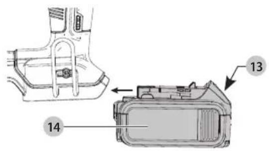
Fig. C
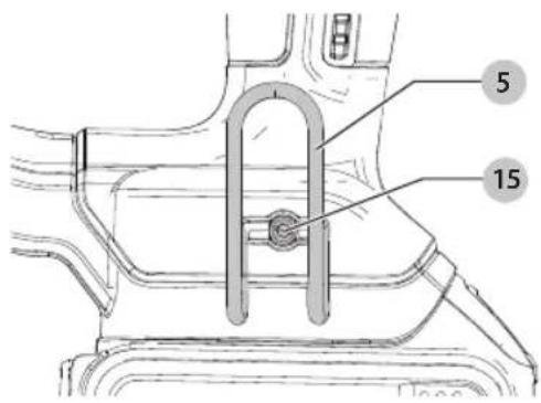
Fig. D
Fig. E
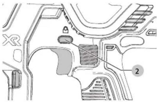
Fig. F
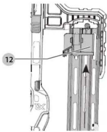
Fig. G
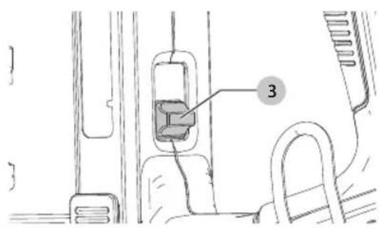
Fig. H
natural_image
Technical diagram showing two views of a robotic device with directional arrows and warning symbols (no text or labels present)Fig.1
natural_image
Technical line drawing of a mechanical assembly with no visible text or symbolsFig. J
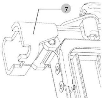
Fig. K
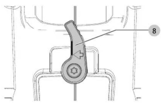
Fig. L
natural_image
Technical line drawing of a mechanical assembly with no visible text or symbolsFig. M Fig. N
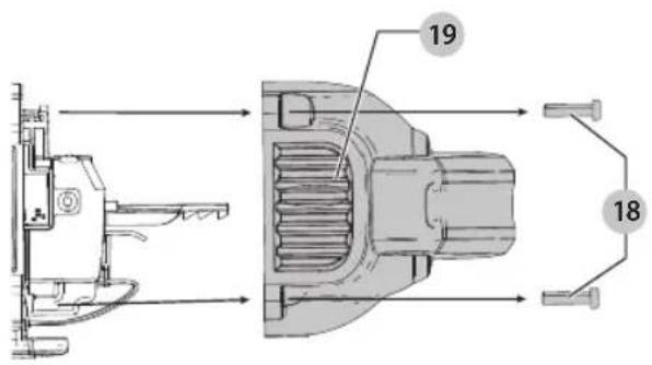
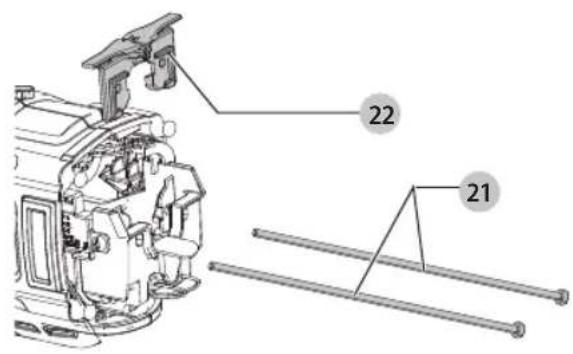
Fig. O
LEDNINGSFRI HÄFTEMASKINE TIL HEGN
DCFS950
Tillykke!
AKKU-HOLZ-STIFTNAGLER
DCFS950
You have chosen a DEWALT tool. Years of experience, thorough product development and innovation make DEWALT one of the most reliable partners for professional power tool users.
Technical Data
| DCFS950 | ||
| Voltage V | DC | 18 |
| Type 1 | ||
| Battery type Li-Ion | ||
| Magazine angle 0^ | ||
| Loading capacity up to 38 staples | ||
| Length of staples mm 40–50 | ||
| Staple thickness mm 3.7–4 | ||
| Weight (without battery pack) kg 4.2 | ||
| Noise values and vibration values (triax vector sum) according to EN60745-2-16 | ||
| L_PA (emission sound pressure level) dB(A) 87 | ||
| L_WM (sound power level) | dB(A) 98 | |
| K (uncertainty for the given sound level) | dB(A) | 3 |
| Vibration emission value a_h = | m/s2 | 3.8 |
| Uncertainty K = | m/s2 | 1.5 |
The vibration emission level given in this information sheet has been measured in accordance with a standardised test given in EN60745 and may be used to compare one tool with another. It may be used for a preliminary assessment of exposure.
WARNING: The declared vibration emission level represents the main applications of the tool. However if the tool is used for different applications, with different accessories or poorly maintained, the vibration emission may differ. This may significantly increase the exposure level over the total working period.
An estimation of the level of exposure to vibration should also take into account the times when the tool is switched off or when it is running but not actually doing the job. This may significantly reduce the exposure level over the total working period.
Identify additional safety measures to protect the operator from the effects of vibration such as: maintain the tool and the accessories, keep the hands warm, organisation of work patterns.
EC-Declaration of Conformity
Machinery Directive

Cordless Fencing Stapler DCFS950
DEWALT declares that these products described under
Technical Data are in compliance with:
2006/42/EC, EN60745-1:2009+A11:2010, EN60745-2-16:2010.
These products also comply with Directive 2014/30/EU and 2011/65/EU. For more information, please contact DEWALT at the following address or refer to the back of the manual.
The undersigned is responsible for compilation of the technical file and makes this declaration on behalf of DEWALT.

Markus Rompel
Vice-President Engineering, PTE-Europe
D-65510, Idstein, Germany
26.01.2017

WARNING: To reduce the risk of injury, read the instruction manual.
Definitions: Safety Guidelines
The definitions below describe the level of severity for each signal word. Please read the manual and pay attention to these symbols.
DANGER: Indicates an imminently hazardous situation which, if not avoided, will result in death or serious injury.
WARNING: Indicates a potentially hazardous situation when, if not avoided, could result in death or serious injury.
CAUTION: Indicates a potentially hazardous situation which, if not avoided, may result in minor or moderate injury.
NOTICE: Indicates a practice not related to personal injury which, if not avoided, may result in property damage.
Dicates risk of electric shock.
Dilutes risk of fire.
| Batteries Chargers/Charge Times (Minutes) | |||||||||||
| Cat # V | DC | Ah Weight (kg) | DCB104 DC | CB107 DCB112 DCB113 DCB115 DCB118 DCB132 DCB119 | |||||||
| DCB546 18/54 | 6.0/2.0 | 1.05 | 60 270 170 | 140 90 | 60 90 | X | |||||
| DCB547 | 18/54 | 9.0/3.0 | 1.46 | 75* | 420 | 270 | 220 | 135* | 75* | 135* | X |
| DCB548 | 18/54 | 12.0/4.0 | 1.44 | 120 | 540 | 350 | 300 | 180 | 120 | 180 | X |
| DCB181 | 18 | 1.5 | 0.35 | 22 | 70 | 45 | 35 | 22 | 22 | 22 | 45 |
| DCB182 | 18 | 4.0 | 0.61 | 60/40** | 185 | 120 | 100 | 60 | 60/40** | 60 | 120 |
| DCB183/B | 18 | 2.0 | 0.40 | 30 | 90 | 60 | 50 | 30 | 30 | 30 | 60 |
| DCB184/B | 18 | 5.0 | 0.62 | 75/50** | 240 | 150 | 120 | 75 | 75/50** | 75 | 150 |
| DCB185 | 18 | 1.3 | 0.35 | 22 | 60 | 40 | 30 | 22 | 22 | 22 | X |
| DCB187 | 18 | 3.0 | 0.54 | 45 | 140 | 90 | 70 | 45 | 45 | 45 | 90 |
| DCB189 | 18 4.0 | 0.54 | 60 185 | 120 100 60 | 60 | 60 120 | |||||
*Date code 201811475B or later
**Date code 201536 or later
GENERAL POWER TOOL SAFETY WARNINGS
WARNING: Read all safety warnings, instructions, indications and specifications provided with this power tool. Failure to follow all instructions listed below may result in electric shock, fire and/or serious injury.
SAVE ALL WARNINGS AND INSTRUCTIONS FOR FUTURE REFERENCE
The term "power tool" in the warnings refers to your mains-operated (corded) power tool or battery-operated (cordless) power tool.
1) Work area safety
a) Keep work area clean and well lit. Cluttered or dark areas invite accidents.
b) Do not operate power tools in explosive atmospheres, such as in the presence of flammable liquids, gases or dust. Power tools create sparks which may ignite the dust or fumes.
c) Keep children and bystanders away while operating a power tool. Distractions can cause you to lose control.
2) Electrical safety
a) Power tool plugs must match the outlet. Never modify the plug in any way. Do not use any adapter plugs with earthed (grounded) power tools.
Unmodified plugs and matching outlets will reduce risk of electric shock.
b) Avoid body contact with earthed or grounded surfaces such as pipes, radiators, ranges and refrigerators. There is an increased risk of electric shock if your body is earthed or grounded.
c) Do not expose power tools to rain or wet conditions. Water entering a power tool will increase the risk of electric shock.
d) Do not abuse the cord. Never use the cord for carrying, pulling or unplugging the power tool. Keep cord away from heat, oil, sharp edges or moving parts. Damaged or entangled cords increase the risk of electric shock.
e) When operating a power tool outdoors, use an extension cord suitable for outdoor use. Use of a cord suitable for outdoor use reduces the risk of electric shock.
f) If operating a power tool in a damp location is unavoidable, use a residual current device (RCD) protected supply. Use of an RCD reduces the risk of electric shock.
3) Personal safety
a) Stay alert, watch what you are doing and use common sense when operating a power tool. Do not use a power tool while you are tired or under the influence of drugs, alcohol or medication. A moment of inattention while operating power tools may result in serious personal injury.
b) Use personal protective equipment. Always wear eye protection. Protective equipment such as a dust mask, non-skid safety shoes, hard hat, or hearing protection used for appropriate conditions will reduce personal injuries.
c) Prevent unintentional starting. Ensure the switch is in the off position before connecting to power source and/or battery pack, picking up or carrying the tool. Carrying power tools with your finger on the switch or energising power tools that have the switch on invites accidents.
d) Remove any adjusting key or wrench before turning the power tool on. A wrench or a key left attached to a rotating part of the power tool may result in personal injury.
e) Do not overreach. Keep proper footing and balance at all times. This enables better control of the power tool in unexpected situations.
f) Dress properly. Do not wear loose clothing or jewellery. Keep your hair, clothing and gloves away from moving parts. Loose clothes, jewellery or long hair can be caught in moving parts.
g) If devices are provided for the connection of dust extraction and collection facilities, ensure these are
connected and properly used. Use of dust collection can reduce dust-related hazards.
4) Power tool use and care
a) Do not force the power tool. Use the correct power tool for your application. The correct power tool will do the job better and safer at the rate for which it was designed.
b) Do not use the power tool if the switch does not turn it on and off. Any power tool that cannot be controlled with the switch is dangerous and must be repaired.
c) Disconnect the plug from the power source and/or the battery pack from the power tool before making any adjustments, changing accessories, or storing power tools. Such preventive safety measures reduce the risk of starting the power tool accidentally.
d) Store idle power tools out of the reach of children and do not allow persons unfamiliar with the power tool or these instructions to operate the power tool. Power tools are dangerous in the hands of untrained users.
e) Maintain power tools. Check for misalignment or binding of moving parts, breakage of parts and any other condition that may affect the power tool's operation. If damaged, have the power tool repaired before use. Many accidents are caused by poorly maintained power tools.
f) Keep cutting tools sharp and clean. Properly maintained cutting tools with sharp cutting edges are less likely to bind and are easier to control.
g) Use the power tool, accessories and tool bits etc., in accordance with these instructions taking into account the working conditions and the work to be performed. Use of the power tool for operations different from those intended could result in a hazardous situation.
5) Battery tool use and care
a) Recharge only with the charger specified by the manufacturer. A charger that is suitable for one type of battery pack may create a risk of fire when used with another battery pack.
b) Use power tools only with specifically designated battery packs. Use of any other battery packs may create a risk of injury and fire.
c) When battery pack is not in use, keep it away from other metal objects like paper clips, coins, keys, nails, screws or other small metal objects that can make a connection from one terminal to another. Shorting the battery terminals together may cause burns or a fire.
d) Under abusive conditions, liquid may be ejected from the battery; avoid contact. If contact accidentally occurs, flush with water. If liquid contacts eyes, additionally seek medical help. Liquid ejected from the battery may cause irritation or burns.
6) Service
a) Have your power tool serviced by a qualified repair person using only identical replacement parts. This will ensure that the safety of the power tool is maintained.
Stapler Safety Warnings
• Always assume that the tool contains fasteners. Careless handling of the stapler can result in unexpected firing of fasteners and personal injury.
- Do not point the tool towards yourself or anyone nearby. Unexpected triggering could discharge a fastener causing an injury.
- Do not actuate the tool unless the tool is placed firmly against the workpiece. If the tool is not in contact with the workpiece, the fastener may be deflected away from your target.
- Disconnect the tool from the power source when the fastener jams in the tool. While removing a jammed fastener, the stapler may be accidentally activated if it is plugged in.
Additional Stapler Safety Warnings
WARNING: When using any stapler, all safety precautions, and declined below, should be followed to avoid the risk of death or serious injury. Read and understand all instructions before operating the tool.
- Hold tool by insulated gripping surfaces when performing an operation where the staple may contact hidden wiring. Contact with a "live" wire will make exposed metal parts of the tool "live" and shock the operator.
• Always wear appropriate personal hearing and other protection during use. Under some conditions and duration of use, noise from this product may contribute to hearing loss.
- Disconnect battery pack from the tool when not in use. Always remove battery pack and remove fasteners from magazine before leaving the area or passing the tool to another operator. Do not carry tool to another work area in which changing location involves the use of scaffoldings, stairs, ladders, and the like, with battery pack connected. Do not make adjustments, perform maintenance or clear jammed fasteners while battery is in place.
- Always use trigger lock-off when tool is not in immediate use. Using the trigger lock-off will prevent accidental discharge.
- Do not remove, tamper with, or otherwise cause the tool, trigger or trigger lock-off, to become inoperable. Do not tape or tie trigger in the on position. Do not remove spring from contact trip. Make daily inspections for free movement of trigger. Uncontrolled discharge could result.
- Inspect tool before use. Do not operate a tool if any portion of the tool, trigger, or trigger lock-off is inoperable, disconnected, altered, or not working properly. Damaged parts or missing parts should be repaired or replaced before use. Refer to Maintenance.
- Do not alter or modify the tool in any way.
• Always assume that the tool contains fasteners.
- Do not point the tool at co-workers or yourself at any time. No horseplay! Work safe! Respect the tool as a working implement.
- Keep bystanders, children, and visitors away while operating a power tool. Distractions can cause you to lose control. When tool is not in use, it should be locked in a safe place, out of the reach of children.
- Do not overreach. Maintain proper footing and balance at all times. Loss of balance may cause personal injury.
- Use the tool only for its intended use. Do not discharge fasteners into open air or any material too hard for the staple to penetrate. Do not use the body of the tool or top cap as a hammer. Discharged staple may follow unexpected path and cause injury.
• Always keep fingers clear of contact trip to prevent injury from inadvertent release of the staple.
• Refer to the Maintenance and Repairs sections for detailed information on the proper maintenance of the tool.
• Always operate the tool in a clean, lighted area. Be sure the work surface is clear of any debris and be careful not to lose footing when working in elevated environments such as rooftops. - Fasteners must be driven straight into the material. Do not tilt the stapler while driving fasteners. Personal injury can result from ricocheted or jammed staples.
- Keep hands and body parts clear of immediate work area.
WARNING: To avoid injury keep hands and body away from the front discharge area of the tool. - Do not use tool in the presence of flammable dust, gases or fumes. This tool produces sparks that can ignite gases or dust causing an explosion. Driving a staple into another staple may also cause a spark.
- Keep face and body parts away from back of the tool cap when working in restricted areas. Sudden recoil can result in impact to the body, especially when stapling into hard or dense material.
- Grip tool firmly to maintain control while allowing tool to recoil away from work surface as fastener is driven.
- Be aware of material thickness when using stapler. A protruding staple may cause injury.
- Stay alert, watch what you are doing and use common sense when operating a power tool. Do not use tool while tired or under the influence of drugs, alcohol, or medication. A moment of inattention while operating power tools may result in serious personal injury.
Residual Risks
In spite of the application of the relevant safety regulations and the implementation of safety devices, certain residual risks cannot be avoided. These are:
- Impairment of hearing.
-
Risk of personal injury due to flying particles.
-
Risk of burns due to accessories becoming hot during operation.
- Risk of personal injury due to prolonged use.
SAVE THESE INSTRUCTIONS
Chargers
Electrical Safety
The electric motor has been designed for one voltage only. Always check that the battery pack voltage corresponds to the voltage on the rating plate. Also make sure that the voltage of your charger corresponds to that of your mains.

Your DEWALT charger is double insulated in accordance with EN60335; therefore no earth wire is required.
If the supply cord is damaged, it must be replaced by a specially prepared cord available through the DEWALT service organisation.
Mains Plug Replacement (U.K. & Ireland Only)
If a new mains plug needs to be fitted:
• Safely dispose of the old plug.
- Connect the brown lead to the live terminal in the plug.
- Connect the blue lead to the neutral terminal.
WARNING: No connection is to be made to the terminal.
Follow the fitting instructions supplied with good quality plugs. Recommended fuse: 3 A.
Using an Extension Cable
An extension cord should not be used unless absolutely necessary. Use an approved extension cable suitable for the power input of your charger (see Technical Data). The minimum conductor size is 1 mm ^2 ; the maximum length is 30 m.
When using a cable reel, always unwind the cable completely. DEWALT chargers require no adjustment and are designed to be as easy as possible to operate.
Important Safety Instructions for All Battery Chargers
SAVE THESE INSTRUCTIONS: This manual contains important safety and operating instructions for compatible battery chargers (refer to Technical Data).
- Before using charger, read all instructions and cautionary markings on charger, battery pack, and product using battery pack.
WARNING: Shock hazard. Do not allow any liquid to get inside charger. Electric shock may result.
WARNING: We recommend the use of a residual current rating with a residual current rating of 30mA or less.
CAUTION: Burn hazard. To reduce the risk of injury, damage only DEWALT rechargeable batteries. Other types of batteries may burst causing personal injury and damage.
CAUTION: Children should be supervised to ensure that they do not play with the appliance.
NOTICE: Under certain conditions, with the charger plugged into the power supply, the exposed charging contacts inside the charger can be shorted by foreign material. Foreign materials of a conductive nature such as, but not limited to, steel wool, aluminum foil or any buildup of metallic particles should be kept away from charger cavities. Always unplug the charger from the power supply when there is no battery pack in the cavity. Unplug charger before attempting to clean
- DO NOT attempt to charge the battery pack with any chargers other than the ones in this manual. The charger and battery pack are specifically designed to work together.
• These chargers are not intended for any uses other than charging DEWALT rechargeable batteries. Any other uses may result in risk of fire, electric shock or electrocution. - Do not expose charger to rain or snow.
- Pull by plug rather than cord when disconnecting charger. This will reduce risk of damage to electric plug and cord.
- Make sure that cord is located so that it will not be stepped on, tripped over, or otherwise subjected to damage or stress.
- Do not use an extension cord unless it is absolutely necessary. Use of improper extension cord could result in risk of fire, electric shock, or electrocution.
- Do not place any object on top of charger or place the charger on a soft surface that might block the ventilation slots and result in excessive internal heat. Place the charger in a position away from any heat source. The charger is ventilated through slots in the top and the bottom of the housing.
- Do not operate charger with damaged cord or plug—have them replaced immediately.
- Do not operate charger if it has received a sharp blow, been dropped, or otherwise damaged in any way. Take it to an authorised service centre.
- Do not disassemble charger; take it to an authorised service centre when service or repair is required. Incorrect reassembly may result in a risk of electric shock, electrocution or fire.
- In case of damaged power supply cord the supply cord must be replaced immediately by the manufacturer, its service agent or similar qualified person to prevent any hazard.
- Disconnect the charger from the outlet before attempting any cleaning. This will reduce the risk of electric shock. Removing the battery pack will not reduce this risk.
- NEVER attempt to connect two chargers together.
- The charger is designed to operate on standard 230V household electrical power. Do not attempt to use it on any other voltage. This does not apply to the vehicular charger.
Charging a Battery (Fig. B)
- Plug the charger into an appropriate outlet before inserting battery pack.
- Insert the battery pack 14 into the charger, making sure the battery pack is fully seated in the charger. The red (charging) light will blink repeatedly indicating that the charging process has started.
- The completion of charge will be indicated by the red light remaining ON continuously. The battery pack is fully charged and may be used at this time or left in the charger. To remove the battery pack from the charger, push the battery release button 13 on the battery pack.
NOTE: To ensure maximum performance and life of lithium-ion battery packs, charge the battery pack fully before first use.
Charger Operation
Refer to the indicators below for the charge status of the battery pack.
Charge Indicators
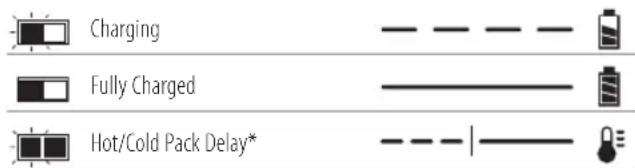
* The red light will continue to blink, but a yellow indicator light will be illuminated during this operation. Once the battery pack has reached an appropriate temperature, the yellow light will turn off and the charger will resume the charging procedure. The compatible charger(s) will not charge a faulty battery pack. The charger will indicate faulty battery by refusing to light.
NOTE: This could also mean a problem with a charger. If the charger indicates a problem, take the charger and battery pack to be tested at an authorised service centre.
Hot/Cold Pack Delay
When the charger detects a battery pack that is too hot or too cold, it automatically starts a Hot/Cold Pack Delay, suspending charging until the battery pack has reached an appropriate temperature. The charger then automatically switches to the pack charging mode. This feature ensures maximum battery pack life.
A cold battery pack will charge at a slower rate than a warm battery pack. The battery pack will charge at that slower rate throughout the entire charging cycle and will not return to maximum charge rate even if the battery pack warms.
The DCB118 charger is equipped with an internal fan designed to cool the battery pack. The fan will turn on automatically when the battery pack needs to be cooled. Never operate the charger if the fan does not operate properly or if ventilation slots are blocked. Do not permit foreign objects to enter the interior of the charger.
Electronic Protection System
XR Li-Ion tools are designed with an Electronic Protection System that will protect the battery pack against overloading, overheating or deep discharge.
The tool will automatically turn off if the Electronic Protection System engages. If this occurs, place the lithium-ion battery pack on the charger until it is fully charged.
Wall Mounting
These chargers are designed to be wall mountable or to sit upright on a table or work surface. If wall mounting, locate the charger within reach of an electrical outlet, and away from a corner or other obstructions which may impede air flow. Use the back of the charger as a template for the location of the mounting screws on the wall. Mount the charger securely using drywall screws (purchased separately) at least 25.4 mm long with a screw head diameter of 7–9 mm, screwed into wood to an optimal depth leaving approximately 5.5 mm of the screw exposed. Align the slots on the back of the charger with the exposed screws and fully engage them in the slots.
Charger Cleaning Instructions
WARNING: Shock hazard. Disconnect the charger from the AC outlet before cleaning. Dirt and grease may be removed from the exterior of the charger using a cloth or soft non-metallic brush. Do not use water or any cleaning solutions. Never let any liquid get inside the tool; never immerse any part of the tool into a liquid.
Battery Packs
Important Safety Instructions for All Battery Packs
When ordering replacement battery packs, be sure to include catalogue number and voltage.
The battery pack is not fully charged out of the carton. Before using the battery pack and charger, read the safety instructions below. Then follow charging procedures outlined.
READ ALL INSTRUCTIONS
- Do not charge or use battery in explosive atmospheres, such as in the presence of flammable liquids, gases or dust. Inserting or removing the battery from the charger may ignite the dust or fumes.
- Never force battery pack into charger. Do not modify battery pack in any way to fit into a non-compatible charger as battery pack may rupture causing serious personal injury.
- Charge the battery packs only in DEWALT chargers.
- DO NOT splash or immerse in water or other liquids.
- Do not store or use the tool and battery pack in locations where the temperature may reach or exceed 40^ (104°F) (such as outside sheds or metal buildings in summer).
- Do not incinerate the battery pack even if it is severely damaged or is completely worn out. The battery pack can explode in a fire. Toxic fumes and materials are created when lithium-ion battery packs are burned.
- If battery contents come into contact with the skin, immediately wash area with mild soap and water. If battery liquid gets into the eye, rinse water over the open eye for 15 minutes or until irritation ceases. If medical attention
is needed, the battery electrolyte is composed of a mixture of liquid organic carbonates and lithium salts.
- Contents of opened battery cells may cause respiratory irritation. Provide fresh air. If symptoms persist, seek medical attention.
WARNING: Burn hazard. Battery liquid may be flammable is exposed to spark or flame.
WARNING: Never attempt to open the battery pack for a yellow reason. If battery pack case is cracked or damaged, do not insert into charger. Do not crush, drop or damage battery pack. Do not use a battery pack or charger that has received a sharp blow, been dropped, run over or damaged in any way (i.e., pierced with a nail, hit with a hammer, stepped on). Electric shock or electrocution may result. Damaged battery packs should be returned to service centre for recycling.
WARNING: Fire hazard. Do not store or carry the battery pack so that metal objects can contact exposed battery terminals. For example, do not place the battery pack in aprons, pockets, tool boxes, product kit boxes, drawers, etc., with loose nails, screws, keys, etc.
CAUTION: When not in use, place tool on its side on a stable surface where it will not cause a tripping or falling hazard. Some tools with large battery packs will stand upright on the battery pack but may be easily knocked over.
Transportation
WARNING: Fire hazard. Transporting batteries can probably cause fire if the battery terminals inadvertently come in contact with conductive materials. When transporting batteries, make sure that the battery terminals are protected and well insulated from materials that could contact them and cause a short circuit. NOTE: Lithium-ion batteries should not be put in checked baggage.
DEWALT batteries comply with all applicable shipping regulations as prescribed by industry and legal standards which include UN Recommendations on the Transport of Dangerous Goods; International Air Transport Association (IATA) Dangerous Goods Regulations, International Maritime Dangerous Goods (IMDG) Regulations, and the European Agreement Concerning The International Carriage of Dangerous Goods by Road (ADR). Lithium-ion cells and batteries have been tested to section 38.3 of the UN Recommendations on the Transport of Dangerous Goods Manual of Tests and Criteria.
In most instances, shipping a DEWALT battery pack will be excepted from being classified as a fully regulated Class 9 Hazardous Material. In general, only shipments containing a lithium-ion battery with an energy rating greater than 100 Watt Hours (Wh) will require being shipped as fully regulated Class 9. All lithium-ion batteries have the Watt Hour rating marked on the pack. Furthermore, due to regulation complexities, DEWALT does not recommend air shipping lithium-ion battery packs alone regardless of Watt Hour rating. Shipments of tools with batteries (combo kits) can be air shipped as excepted if the Watt Hour rating of the battery pack is no greater than 100 Whr.
ENGLISH
Regardless of whether a shipment is considered excepted or fully regulated, it is the shipper's responsibility to consult the latest regulations for packaging, labeling/marking and documentation requirements.
The information provided in this section of the manual is provided in good faith and believed to be accurate at the time the document was created. However, no warranty, expressed or implied, is given. It is the buyer's responsibility to ensure that its activities comply with the applicable regulations.
Transporting the FLEXVOLT™ Battery
The DEWALT FLEXVOLT™ battery has two modes: Use and Transport.
Use Mode: When the FLEXVOLT ^™ battery stands alone or is in a DEWALT 18V product, it will operate as an 18V battery. When the FLEXVOLT ^™ battery is in a 54V or a 108V (two 54V batteries) product, it will operate as a 54V battery.
Transport Mode: When the cap is attached to the FLEXVOLT ^™ battery, the battery is in Transport mode. Keep the cap for shipping.
When in Transport mode, strings of cells are electrically disconnected within the pack resulting in 3 batteries with a
lower Watt hour (Wh) rating as compared to 1 battery with a higher Watt hour rating. This increased quantity of 3 batteries with the lower Watt hour rating can exempt the pack from certain shipping regulations that are imposed upon the higher Watt hour batteries.
For example, the Transport Wh rating might indicate 3 x 36 Wh, meaning 3 batteries of 36 Wh each.
Example of Use and Transport Label Marking
The Use Wh rating might indicate 108 Wh (1 battery implied).

Storage Recommendations
- The best storage place is one that is cool and dry away from direct sunlight and excess heat or cold. For optimum battery performance and life, store battery packs at room temperature when not in use.
- For long storage, it is recommended to store a fully charged battery pack in a cool, dry place out of the charger for optimal results.
NOTE: Battery packs should not be stored completely depleted of charge. The battery pack will need to be recharged before use.
Labels on Charger and Battery Pack
In addition to the pictographs used in this manual, the labels on the charger and the battery pack may show the following pictographs:

Read instruction manual before use.

See Technical Data for charging time.

Do not probe with conductive objects.

Do not charge damaged battery packs.

Do not expose to water.

Have defective cords replaced immediately.

Charge only between 4 °C and 40 °C.

Only for indoor use.

Discard the battery pack with due care for the environment.

Charge DEWALT battery packs only with designated DEWALT chargers. Charging battery packs other than the designated DEWALT batteries with a DEWALT charger may make them burst or lead to other dangerous situations.

Do not incinerate the battery pack.

USE (without transport cap). Example: Wh rating indicates 108 Wh (1 battery with 108 Wh).
TRANSPORT (with built-in transport cap). Example: Wh rating indicates 3 x 36 Wh (3 batteries of 36 Wh).
Battery Type
The DCFS950 operates on a 18 volt battery pack.
These battery packs may be used: DCB181, DCB182, DCB183, DCB183B, DCB184, DCB184B, DCB185, DCB187, DCB546, DCB547. Refer to Technical Data for more information.
Package Contents
The package contains:
1 Fencing stapler
1 Charger (P2 models only)
2 Battery packs (P2 models only)
1 Kitbox (P2 models only)
1 Instruction manual
- Check for damage to the tool, parts or accessories which may have occurred during transport.
• Take the time to thoroughly read and understand this manual prior to operation.
Markings on Tool
The following pictograms are shown on the tool:

Read instruction manual before use.

Wear ear protection.

Wear eye protection.

Visible radiation. Do not stare into light.

Length of staples.

Staple thickness.

Loading capacity.

Suitable staple collation angle.
Date Code Position (Fig. A)
The date code 17, which also includes the year of manufacture, is printed into the housing.
Example:
2019 XX XX
Year of Manufacture
Description (Fig. A)
WARNING: Never modify the power tool or any part of it. Damage or personal injury could result.
1 Trigger
2 Trigger lock-off
3 Tool free speed select
4 Tool free mode select
5 Utility hook
6 Tool free depth adjust
7 Contact trip
Intended Use
Your fencing stapler is intended ONLY for use in driving staples into wood. This tool has two operating modes, a sequential operating mode and a unique rapid sequential operating mode (RapidCycle). Read the section of the manual Selecting the
Mode before using the tool to make sure you are selecting the proper mode for your application.
DO NOT use under wet conditions or in the presence of flammable liquids or gases.
Your fencing stapler is a professional power tool.
Only DEWALT staples meeting applicable building code requirements should be used in this tool.
This tool is intended for use by construction professionals.
8 Tool free stall release
9 LED work lights (x2)
10 Magazine
11 Magazine release
12 Pusher
13 Battery release button
14 Battery
DO NOT let children come into contact with the tool. Supervision is required when inexperienced operators use this tool.
- Young children and the infirm. This appliance is not intended for use by young children or infirm persons without supervision.
- This product is not intended for use by persons (including children) suffering from diminished physical, sensory or mental abilities; lack of experience, knowledge or skills unless they are supervised by a person responsible for their safety. Children should never be left alone with this product.
Dry Fire Lock Out
Your stapler is equipped with a dry fire lockout which prevents the tool from actuating when the magazine is nearly empty.
When 5 staples remain in the magazine, the tool ceases to operate. Refer to Loading the Tool to reload a stick of collated staples.
ASSEMBLY AND ADJUSTMENTS
WARNING: To reduce the risk of serious personal injury, turn tool off and disconnect battery pack before making any adjustments or removing/installing attachments or accessories. An accidental start-up can cause injury.
WARNING: Use only DEWALT battery packs and chargers.
Inserting and Removing the Battery Pack from the Tool (Fig. B)
NOTE: Make sure your battery pack 14 is fully charged.
To Install the Battery Pack into the Tool Handle
- Align the battery pack 14 with the rails inside the tool's handle (Fig. B).
- Slide it into the handle until the battery pack is firmly seated in the tool and ensure that you hear the lock snap into place.
To Remove the Battery Pack from the Tool
- Press the release button 13 and firmly pull the battery pack out of the tool handle.
- Insert battery pack into the charger as described in the charger section of this manual.
Fuel Gauge Battery Packs (Fig. B)
Some DEWALT battery packs include a fuel gauge 23 which consists of three green LED lights that indicate the level of charge remaining in the battery pack.
To actuate the fuel gauge, press and hold the fuel gauge button. A combination of the three green LED lights will illuminate designating the level of charge left. When the level of charge in the battery is below the usable limit, the fuel gauge will not illuminate and the battery will need to be recharged.
NOTE: The fuel gauge is only an indication of the charge left on the battery pack. It does not indicate tool functionality and is subject to variation based on product components, temperature and end-user application.
ENGLISH
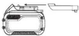
Utility Hook (Fig. C)
The DEWALT cordless staplers include an integrated utility hook 5 and can be attached to either side of the tool to accommodate left- or right-handed users.
If the hook is not desired at all, it can be removed from the tool.
To Remove Utility Hook
- Remove battery pack from tool.
- To switch the tool from right- to left-hand usage simply remove the screw 15 from the opposite side of the tool and reassemble on the other side.
- Replace battery pack.
WARNING: Remove staples from magazine before making any adjustments or servicing this tool. Failure to do so may result in serious injury.
WARNING: Disconnect battery pack from tool before making any adjustments, changing accessories, servicing, or moving the tool. Such preventative safety measures reduce the risk of starting the tool accidentally.
CAUTION: When not in use, place tool on its side on a double surface where it will not cause a tripping or falling hazard. Some tools with large battery packs will stand upright on the battery pack but may be easily knocked over.
OPERATION (FIG. A)
Instructions for Use
WARNING: Always observe the safety instructions and applicable regulations.
WARNING: To reduce the risk of serious personal injury, turn tool off and disconnect battery pack before making any adjustments or removing/installing attachments or accessories. An accidental start-up can cause injury.
WARNING: Read the section titled Stapler Safety Warnings at the beginning of this manual. Always wear eye and ear protection when operating this tool. Keep the stapler pointed away from yourself and others. For safe operation, complete the following procedures and checks before each use of the stapler.
- Wear proper eye, hearing and respiratory protection.
- Remove battery pack from tool.
- Lock the pusher 12 in the back position and remove all staples from the magazine.
- Check for smooth and proper operation of contact trip and pusher latch. Do not use tool if either assembly is not functioning properly. NEVER use a tool that has the contact trip restrained in the up position.
- NEVER use a tool that has damaged parts.
WARNING: To reduce the risk of personal injury, connect battery pack from tool before performing maintenance, clearing a jammed staple, leaving work area, moving tool to another location or handing the tool to another person.
Proper Hand Position (Fig. D)
WARNING: To reduce the risk of serious personal injury, ALWAYS use proper hand position as shown.
WARNING: To reduce the risk of serious personal injury, ALWAYS hold securely in anticipation of a sudden reaction.
Proper hand position requires one hand on the main handle 16 as shown in Fig. D.
Preparing the Tool (Fig. A)
NOTICE: NEVER spray or in any other way apply lubricants or cleaning solvents inside the tool. This can seriously affect the life and performance of the tool.

NOTE: The battery pack is not fully charged out of the carton. Follow instructions outlined (refer to Charging Operations).
- Read the Stapler Safety Warnings section of this manual.
- Wear eye and ear protection.
- Remove battery from tool.
- Ensure magazine is empty of all fasteners.
- Check for smooth and proper operation of contact trip and pusher 12. Do not use tool if either assembly is not functioning properly. NEVER use a tool that has the contact trip restrained in the actuated position.
- Keep tool pointed away from yourself and others.
- Insert fully charged battery pack.
Using the Trigger Lock-off (Fig. E)
WARNING: To reduce the risk of serious personal injury, do not keep trigger depressed when tool is not in use. Keep the trigger lock-off switch LOCKED (Fig. E) when the tool is not in use.
WARNING: To reduce the risk of serious personal injury, lock off trigger, disconnect battery pack from tool and remove staples from magazine before making adjustments.
Each DEWALT stapler is equipped with a trigger lock-off 2 which when pushed to the right as shown in Figure E, prevents the tool from firing a staple by locking the trigger and bypassing power to the motor.
When the trigger lock-off is pressed to the left, the tool will be fully operational. The trigger lock-off should always be locked off (Fig. E) whenever any adjustments are made or when tool is not in immediate use.
NOTICE: Do not store tool with battery pack installed. To prevent damage to the pack and to ensure best battery life, store battery packs out of the tool or charger in a cool, dry location.
Loading the Tool (Fig. F)
WARNING: Keep the tool pointed away from yourself and others.
WARNING: Never load staples with the contact trip or trigger activated.
WARNING: Always remove battery pack before loading or unloading staples.
CAUTION: Keep fingers clear of pusher latch track to prevent injury.
WARNING: The trigger lock-off should always be engaged whenever any adjustments are made or when tool is not in use.
- Turn the stapler upside down.
- Slide the spring-loaded pusher 12 to the base of the magazine to lock it into place.
- Drop staple strips into the loading slot of the magazine, making sure the staple heads align correctly with the slot opening. (Refer to Technical Data to determine compatible size.)
nOTE: Staples cannot be loaded near the nose of the stapler. - Keeping fingers clear of the track, close the magazine by releasing the pusher latch. Carefully allow the latch to slide forward and engage the staple strip.
Unloading the Tool
WARNING: The trigger lock-off should always be locked on whenever any adjustments are made or when tool is not in use.
- Remove the battery from your stapler.
- Slide the spring-loaded pusher latch to the base of the magazine to lock it into place.
- Tip the tool up until the fastener strip slides freely out of the magazine.
- With battery removed, check the nosepiece to verify there are no staples remaining.
NOTE: The tool is equipped with a magnet in the nose area for improved tool performance. When unloading, always verify that the small sticks of staples are not held to the magnetized nosepiece.
Speed Setting Summary (Fig. A, G, H)
This stapler is equipped with a tool free speed select switch 3 to adjust the tool for different applications.
In the event staples are not driving to depth in power setting 1, you may have to switch to power 2 or 3 for additional driving power.
NOTICE: Driving staples into soft materials at high speed settings will cause excessive wear to your tool and may result in early failures.
| Speed Setting Application Typical Staple Length | ||
| 1 | Shorter staple length / minimal staple drive desired | 40 mm |
| 2 | Increased staple drive desired for medium to large staple lengths | 45–50 mm |
| 3 | Stapling to End Posts & Braces / maximum staple drive desired | 45–50 mm |
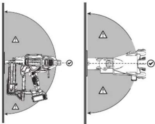
WARNING: Staples must be driven straight into the radial. Do not tilt stapler while driving fasteners. Refer
to Fig. H. Staple retention values improve when the tool is fired perpendicular to the material.
The tool can be fired/actuated by pulling the trigger 1 in one of two modes: sequential mode or RapidCycle mode. Refer to Selecting the Mode for detailed instructions for firing in each mode.
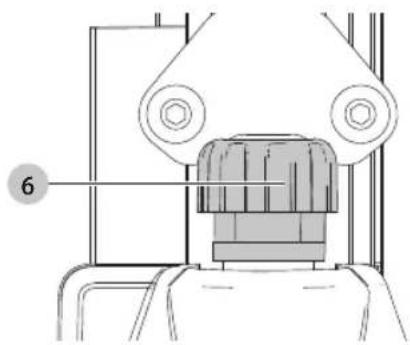
Adjusting Depth (Fig. I)
The depth that the staple is driven can be adjusted using the tool free depth adjust 6 on the nose of the tool.
WARNING: To reduce risk of serious injury from accidental actuation when attempting to adjust depth, ALWAYS:
- Remove battery pack
- Engage trigger lock-off.
• Always point the nose of the stapler away from you. -
Avoid contact with trigger during adjustments.
-
To drive the staple shallower, rotate the tool free depth adjust 6 to the left.
- To drive a staple deeper, rotate the tool free depth adjust 6 to the right.
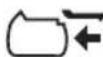
Selecting the Mode (Fig. A)
To select standard sequential mode, slide the tool free mode selector switch 4 to display the single arrow (◀) icon.
To select rapid sequential operating mode (RapidCycle), slide the tool free mode selector switch 4 to display the double arrow (◀) icon.
NOTE: Battery life in RapidCycle mode will be shorter than in standard sequential mode. Leaving the tool in standard sequential will give maximum battery life.
Sequential Mode
The sequential mode is used for intermittent stapling. It offers the maximum battery life for driving staples.
- Using the tool free mode selector switch 4, select the sequential mode.
- Release the trigger lock-off 2.
- Push the contact trip 7 against the work surface.
- Pull the trigger switch 1 to actuate the tool.
- Release the trigger and raise the stapler from the work surface.
- Repeat steps 3–5 to actuate the next staple.
RapidCycle Mode
In RapidCycle mode, the motor rotation speed is automatically restored after driving a staple to allow fast consecutive stapling. While offering the ability to drive more staples in less time, this mode quickly depletes the battery charge.
- Using the tool free mode selector switch 4 to select the RapidCycle mode.
- Release the trigger lock-off 2.
- Push the contact trip 7 against the work surface.
- Pull the trigger switch 1 to actuate the tool.
ENGLISH
- Release the trigger and raise the stapler from the work surface.
NOTE: The tool motor returns to full speed automatically without the contact trip 7 being depressed.
- Repeat steps 3–5 to actuate the next staple.
Multi-Angle Contact Trip (Fig. J)
The contract trip 7 has three notches to allow the user to locate the wire depending on the desired angle they want to staple, allowing the user to drive the staple at angle to the wood grain up to 45 degrees.
Headlights/LED Indicator (Fig. A)
There are LED work lights 9 located on the front of the tool on each side of the magazine.
 | LOW BATTERYReplace battery with a charged pack. |
 | HOT PACKLet the battery cool or replace it with a cool pack. |
 | JAM/STALL CONDITIONRotate the stall release lever to release.Refer to Stall Release or Clearing a Jammed Staple. |
  | HOT TOOL (Both LEDs Flashing)Let the tool cool down before continuing use. |
  or any other combination. or any other combination. | ERRORReset tool by removing and reinserting battery pack or cycling trigger lock-off.If error code persist, take tool to an authorised DEWALT service center. |
Stall Release (Fig. K)
If the stapler is used in harder material where all available energy in the motor is used to drive a fastener, the tool may stall. The driver will not complete the drive cycle and the jam/stall indicator will flash. Rotate the tool free stall release lever 8 on the tool and the mechanism will release.
NOTE: The tool will disable itself and not reset until the battery pack has been removed and reinserted. If the driver does not automatically return to the home position, proceed to Clearing a Jammed Staple. If the unit continues to stall please review the material and fastener length to be sure that it is not too rigorous an application. The stapler could also be overheated and needs time to cool before further use.
Clearing a Jammed Staple (Fig. A, L)
WARNING: To reduce the risk of serious personal injury, disconnect battery pack from tool before making any adjustments, changing accessories,
servicing, or moving the tool. Such preventative safety measures reduce the risk of starting the tool accidentally.
CAUTION: When removing a jammed staple, DO not orient the stapler with the nose up or with the battery foot up. Positioning the stapler this way makes the jammed staple or pieces of the staple more likely to be ingested into the stapler. If any portion of a staple is ingested into the tool, the staple should be retrieved by removing the top cap.
If a staple becomes jammed in the nosepiece, keep the tool pointed away from you and follow these instructions to clear:
- Remove battery pack from tool and engage trigger lock-off.
- After laying the tool on its side, slide the spring-loaded pusher 12 to the base of the magazine to lock it into place and unload staple strip.
- Rotate the magazine release 11 and rotate the magazine 10 forward.
- Remove jammed/bent staple, using pliers if necessary.
CAUTION: If any portion of a staple is ingested into the cap, the staple should be retrieved by removing the top cap.
- If the driver is in the down position, rotate the stall release lever on the top of the stapler.
NOTE: If the driver will not reset after rotating the stall release lever, manually resetting the blade with a long screw driver may be necessary.
-
Rotate the magazine back into position under the nose of the tool and close the magazine release lever.
-
Reinsert battery pack.
NOTE: The tool will disable itself and not reset until the battery pack has been removed and reinserted.
-
Reinsert staples into magazine (refer to Loading the Tool).
-
Release the pusher latch.
-
Disengage the trigger lock-off when ready to continue stapling.
NOTE: Should staples jam frequently or the driver continually fail to reset, have tool serviced by an authorised DEWALT service centre.
Cold Weather Operation
When operating tools at temperatures below freezing:
-
Keep tool as warm as possible prior to use.
-
Actuate the tool 10 or 15 times into scrap lumber before using.
Hot Weather Operation
Tool should operate normally. However, keep tool out of direct sunlight as excessive heat can deteriorate bumpers and other rubber parts resulting in increased maintenance.
MAINTENANCE
Your DEWALT power tool has been designed to operate over a long period of time with a minimum of maintenance. Continuous satisfactory operation depends upon proper tool care and regular cleaning.
WARNING: To reduce the risk of serious personal injury, turn tool off and disconnect battery pack before making any adjustments or removing/installing attachments or accessories. An accidental start-up can cause injury.
The charger and battery pack are not serviceable.
ACTION Clean magazine, pusher, and contact trip mechanism.
WHY Permits smooth operation of magazine, reduces wear, and prevents jams.
HOW Blowing off the tool with compressed air is the most effective way to clean the tool. The use of oils, lubricants periodically or solvents is not recommended as they tend to attract debris and/or damage the plastic parts of the tool.
ACTION Before each use, check to ensure all screws and fasteners are tight and undamaged.
WHY Prevents jams and premature failure of tool parts.
HOW Tighten loose screws using the appropriate hex wrench or screwdriver.

Lubrication
NOTICE: NEVER spray or in any other way apply lubricants or cleaning solvents inside the tool. This can seriously affect the life and performance of the tool.

DeWALT tools are properly lubricated at the factory and are ready for use. However, it is recommended that, once a year, you take or send the tool to a certified service centre for a thorough cleaning and inspection.

Cleaning
WARNING: Blow dirt and dust out of the main housing is dry air as often as dirt is seen collecting in and around the air vents. Wear approved eye protection and approved dust mask when performing this procedure.
WARNING: Never use solvents or other harsh chemicals for cleaning the non-metallic parts of the tool. These chemicals may weaken the materials used in these parts. Use a cloth dampened only with water and mild soap. Never let any liquid get inside the tool; never immerse any part of the tool into a liquid.
Optional Accessories
WARNING: Since accessories, other than those offered by DEWALT, have not been tested with this product, use of such accessories with this tool could be hazardous. To reduce the risk of injury, only DEWALT recommended accessories should be used with this product.
Consult your dealer for further information on the appropriate accessories.
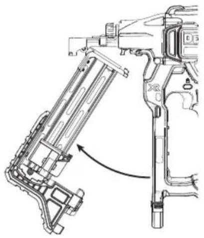
Driver Blade Replacement Kit (Fig. M-O)
WARNING: For your own safety, read the tool instruction manual before using any accessory. Failure to heed these warnings may result in serious personal injury and damage to the tool and the accessory. When servicing this tool, use only identical replacement parts.
NOTICE: All the mechanical parts of the driver replacement kit are shown for convenience and verification of inclusion.
To Change a Worn Driver Blade:
-
Using a T-20 Torx, loosen the four screws 18 on either side of the unit.
-
Remove the four screws. Refer to Figure M.
-
Remove housing end cap 19. Refer to Figure M.
-
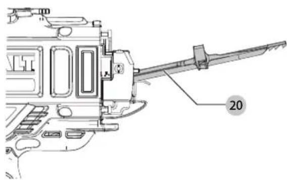
Push up on the rear of the driver 20 until you hear a click, then push the driver forward while holding it in this position until it passes the upper bumper assembly 22.
-
Remove guide rods 21. Refer to Figure N.
-
Remove upper bumper assembly.
-
Pull driver back towards you (or rear of tool). Lift up driver while rotating driver clockwise until driver clears rail locator casting. Remove driver from tool. Refer to Figure O.
-
Replace driver and follow steps in reverse to reassemble
-
Ensure new driver slides smoothly through the tool before full reassembly.
-
Return the driver, guide rods, bumpers and housing end cap back onto the unit. It is important to try the alignment of the driver and the flywheel before screwing the housing end cap back on to the unit. This can be done by connecting a battery and pushing then releasing the nose of the unit against a bench or hard surface. This will start the motor spinning.
NOTE: When the driver and the flywheel are correctly aligned, you will hear the motor coast back down from full speed. If the driver and the flywheel are not correctly aligned, the motor may not start up, may slow down much faster than normal along with a loud grinding noise from the unit. If this happens remove and reseat the driver making sure the bumpers are seated correctly.
WARNING: Always test the unit by firing 40 mm staples in speed 1 into scrap material, to ensure that the tool is working properly. If tool does not operate properly, contact a recognised DEWALT service centre immediately.
Protecting the Environment
Separate collection. Products and batteries marked with this symbol must not be disposed of with normal household waste.
Products and batteries contain materials that can
be recovered or recycled reducing the demand for raw materials. Please recycle electrical products and batteries according to local provisions. Further information is available at www.2helpU.com.
Rechargeable Battery Pack
This long life battery pack must be recharged when it fails to produce sufficient power on jobs which were easily done before. At the end of its technical life, discard it with due care for our environment:
- Run the battery pack down completely, then remove it from the tool.
- Li-lon cells are recyclable. Take them to your dealer or a local recycling station. The collected battery packs will be recycled or disposed of properly.
TROUBLESHOOTING GUIDE
WARNING: To reduce the risk of serious personal injury, turn tool off and disconnect battery pack before making any adjustments or removing/installing attachments or accessories. An accidental start-up can cause injury.
| SYMPTOM CAUSE FIX | ||
| Motor does not run with contact trip depressed. | Trigger lock in locked position. Unlock trigger lock. | |
| Dryfire lock out engaged, blocking contact trip from traveling fully. | Load more staples into magazine. | |
| Tool is stalled, locking the motor from rotating. Rotate the stall release lever on the tool and the mechanism will release. If driver does not return, remove battery and manually push driver back to home position. | ||
| Tool is hot. (Check LED indicator to verify these conditions.) | Let the tool cool down before continuing use. | |
| Battery is hot. (Check LED indicator to verify these conditions.) | Let the battery cool or replace it with a cool pack. | |
| Bent contact trip. See authorised service centre. | ||
| Motor stops running after 4 seconds. Normal operation, release contact trip and redepress. | ||
| Terminals are dirty or damaged. See authorised service centre. | ||
| Damaged internal electronics. See authorised service centre. | ||
| Damaged Trigger. See authorised service centre. | ||
| Low battery charge or damaged battery. Check charge level if pack shows state-of-charge.Charge or replace battery pack if necessary. | ||
| Tool does not actuate (motor runs but will not fire.) | Dry fire lock out is engaged with only 5 staples remaining in magazine. | Load more staples in magazine to disengage dryfire lockout. |
| Jammed staple/drive blade not returned to home position. | Remove battery, clear jammed staple, cycle stall release lever, (push driver up manually if necessary) reinsert battery pack. | |
| Damaged driver. Replace driver with kit, or see authorised service centre. | ||
| Jammed internal mechanism. See authorised service centre. | ||
| Damaged internal electronics. See authorised service centre. | ||
| Motor starts up but generates a lot of noise. | Jammed staple and driver is stuck in down position. | Use stall release lever, clear and jammed staples, and return driver manually if necessary. |
| Damaged driver. Replace driver with kit, or see authorised service centre. | ||
| Driver blade continues to get stuck in down position or does not travel freely. | Jammed staple and driver is stuck in down position. | Use stall release lever, clear any jammed staples, and return driver manually if necessary. |
| Debris in nosepiece. Clean nose area and watch closely for small pieces of broken staples stuck in the track. Refer to Clearing a Jammed Staple. | ||
| Damaged or worn driver. Replace driver with kit, or see authorised service centre. | ||
| SYMPTOM CAUSE FIX | ||
| Tool operates but does not drive staples fully. | Speed select setting in wrong position. Select higher power setting. | |
| Depth adjust setting incorrect. Adjust tool free depth adjust dial. | ||
| Tool not firmly applied to workpiece. Apply adequate force to tool securing it tightly to workpiece. See instruction manual. | ||
| Material and staple length. If the unit continues to stall (forcing the need to rotate the stall release lever) choose the appropriate material and staple length that is not too rigorous of an application. | ||
| Damaged or worn driver tip. Replace driver with kit, or see authorised service centre. | ||
| Damaged actuation mechanism. See authorised service centre. | ||
| Tool operates, but no staple is driven. | Incorrect staples. Use only the recommended staples. Refer to Technical Data. | |
| Debris in nosepiece. Clean nose area and watch closely for small pieces of broken staples stuck in the track. | ||
| Debris in magazine Clean magazine. | ||
| Damaged or worn driver. Replace driver with kit, or see authorised service centre. | ||
| Worn magazine. Replace magazine. See authorised service centre. | ||
| Damaged pusher spring. Replace spring. See authorised service centre. | ||
| Jammed staple. | Incorrect staples. Use only the recommended staples. Refer to Technical Data. | |
| Magazine not secured after previous jam clear/ inspection. Make sure to magazine is latched properly. | ||
| Damaged or worn driver. Replace driver with kit, or see authorised service centre. | ||
| Material and staple length. If the unit continues to stall (forcing the need to rotate the stall release lever) choose the appropriate material and staple length that is not too rigorous an application. | ||
| Debris in nosepiece. Clean nose area and watch closely for small pieces of broken staples stuck in the track. | ||
| Damaged pusher spring. Replace springs. See authorised service centre. | ||
| Tool is not yet run-in. New tools can take 100–500 staples for parts to mesh and wear in together. Drive shorter staples during this period if experiencing difficulty fully driving staples. | ||
| Worn magazine. Replace magazine. See authorised service centre. | ||
| Staple drives too deep. Power setting too high. Select lower power setting. | ||
| Depth adjust setting incorrect. Adjust tool free depth adjust dial. | ||
| Staple bends. | Staple hit knot in wood. Move 76 mm and try again. | |
Batterie rechargeable
Vice-President Engineering, PTE-Europa
DEWALT, Richard-Slinger-Strase 11,
BEWAAR ALLE WAARSCHUWINGEN EN INSTRUCTIES ALS TOEKOMSTIG REFERENTIEMATERIAAL
If the stapler is used in harder material where all available energy in the motor is used to drive a fastener, the tool may stall. The driver will not complete the drive cycle and the jam/stall indicator will flash. Rotate the tool free stall release lever 8 on the tool and the mechanism will release.
nEDERLanDs
DAGLIG VEDLIKEHOLDSPLAN
Markus Rompel