USER MANUAL Dtect 200 C Professional BOSCH
natural_image
Illustration of a Bosch handheld device with control panel and display screen (no visible text or symbols)
English ......Page 37
Français......Page 61
text_image
A
(25)
(9)
(10)
text_image
B
(25)
(26)
(9)
(28)
④
③
①
①
②
(27)
6
text_image
C
x
y
A
B
BOSCH
Brick / Universal
x
y
A
B
6.0cm
metal
1 609 92A 7LD | (06.05.2022) Bosch Power Tools
text_image
D
BOSCH
(29)
(30)
(31)
(32)
CR 2062
3V
(29)
Bosch Power Tools 1 609 92A 7LD | (06.05.2022)
8 | Deutsch
Inhaltsverzeichnis
natural_image
Concentric circles on a dark background with 'Concrete' title and play button icon (no readable text or symbols)
text_image
Leakage Detection
www.bosch-pt.com/serviceaddresses
Transport
Safety Instructions ...... page 37
Product Description and Specifications ...... page 39
Intended Use...... page 39
Product Features...... page 39
Technical Data...... page 41
Operation...... page 43
Measuring Tool Power Supply ...... page 44
Operation with lithium-ion rechargeable battery pack (see figure A) ..... page 44
Operation with non-rechargeable batteries (see figure B)...... page 44
Starting Operation ...... page 45
Switching on/off ...... page 45
Overview of the measuring modes...... page 45
Measuring Mode ...... page 45
How it Works ...... page 45
Change the wall type...... page 46
Wall Type ...... page 46
Wall Type ...... page 47
Wall Type ...... page 47
Wall Type ...... page 47
Wall Type ...... page 47
Wall Type ...... page 47
Wall Type ...... page 47
Change the view...... page 47
...... page 48
...... page 49
...... page 51
...... page 51
Measuring Mode ...... page 52
Measuring Mode ...... page 52
Save/transfer the measuring results ...... page 53
36 | English
Saving Measuring Results as an Image ...... page 53
Data transfer via USB Type-C® interface ...... page 53
Data Transfer via SD Card...... page 53
Main Menu...... page 54
Navigating in the menu...... page 54
Menu options...... page 54
Measuring Tool Software Update...... page 55
Errors – Causes and Corrective Measures...... page 55
Maintenance and Service...... page 56
Maintenance and Cleaning ...... page 56
Inserting/changing the button cell (see figure D)...... page 56
After-Sales Service and Application Service...... page 56
You can find further service addresses at:...... page 57
Transport ...... page 57
Disposal page 57
Only for EU countries:...... page 58
Only for United Kingdom: ...... page 58
Battery packs/batteries:...... page 58
English
Safety Instructions

All instructions must be read and observed. The safeguards integrated into the measuring tool may be compromised if the measuring tool is not used in accordance with these instructions. STORE THESE INSTRUCTIONS IN A SAFE PLACE.
▶ Have the measuring tool serviced only by a qualified specialist using only original replacement parts. This will ensure that the safety of the measuring tool is maintained.
▶ Do not use the measuring tool in explosive atmospheres which contain flammable liquids, gases or dust. Sparks may be produced inside the measuring tool, which can ignite dust or fumes.
▶ Do not open the battery. There is a risk of short-circuiting.
In case of damage and improper use of the battery, vapours may be emitted. The battery can set alight or explode. Ensure the area is well ventilated and seek medical attention should you experience any adverse effects. The vapours may irritate the respiratory system.
If used incorrectly or if the battery is damaged, flammable liquid may be ejected from the battery. Contact with this liquid should be avoided. If contact accidentally occurs, rinse off with water. If the liquid comes into contact with your eyes, seek additional medical attention. Liquid ejected from the battery may cause irritation or burns.
The battery can be damaged by pointed objects such as nails or screwdrivers or by force applied externally. An internal short circuit may occur, causing the battery to burn, smoke, explode or overheat.
When the battery is not in use, keep it away from paper clips, coins, keys, nails, screws or other small metal objects that could make a connection from one terminal to another. A short circuit between the battery terminals may cause burns or a fire.
▶ Only use the battery with products from the manufacturer. This is the only way in which you can protect the battery against dangerous overload.
▶ Only charge the batteries using chargers recommended by the manufacturer. A charger that is suitable for one type of battery may pose a fire risk when used with a different battery.
38 | English


Protect the battery against heat, e.g. against continuous intense sunlight, fire, dirt, water and moisture. There is a risk of explosion and short-circuiting.
The measuring tool may not be 100 % accurate for technological reasons. To eliminate hazards, familiarise yourself with further sources of information, such as building plans and photographs taken during construction, etc. before carrying out any drilling, sawing or routing work on walls, ceilings or floors. The accuracy of the measuring tool may be affected by environmental influences, such the level of humidity or there being other electronic devices nearby. The structure and condition of the walls (e.g. damp, building materials containing metal, electrically conductive wallpaper, insulating materials, tiles) and the number, type, size and position of the objects may distort the measuring results.
▶ If there are gas pipes in the building, check to ensure that none of them have been damaged after completing any work on walls, ceilings or floors.
▶ Switch off power consumers and make sure that live cables are de-energised before drilling, sawing or milling into walls, ceilings or floors. After performing any kind of work, check to ensure that objects placed on the substrate are not live.
When attaching objects to dry walls, and in particular when attaching them to the substructure, check to ensure that both the wall and the fastening materials have a sufficient load-bearing capacity.


WARNING


Ensure that the coin cell is kept out of the reach of children. Coin cells are dangerous.
▶ Coin cells must never be swallowed or inserted into any other part of the body. If you suspect that someone has swallowed a coin cell or that a coin cell has entered the body in another way, seek medical attention immediately. Swallowing coin cells can result in severe internal burns and death within 2 hours.
▶ Ensure that coin cell replacement is carried out properly. There is a risk of explosion.
▶ Only use the coin cells listed in this operating manual. Do not use any other coin cells or other forms of electrical power supply.
▶ Do not attempt to recharge the coin cell and do not short circuit the coin cell. The coin cell may leak, explode, catch fire and cause personal injury.
▶ Remove and dispose of drained coin cell correctly. Drained coin cell may leak and damage the product or cause personal injury.
▶ Do not overheat the coin cell or throw it into fire. The coin cell may leak, explode, catch fire and cause personal injury.
▶ Do not damage the coin cell and take the coin cell apart. The coin cell may leak, explode, catch fire and cause personal injury.
▶ Do not allow damaged coin cells to come into contact with water. Leaking lithium may mix with water to create hydrogen, which could cause a fire, an explosion, or personal injury.
▶ If the coin cell holder cannot be closed correctly and fully, stop using the measuring tool, remove the coin cell and have the measuring tool repaired.
Product Description and Specifications
Please observe the illustrations at the beginning of this operating manual.
Intended Use
The measuring tool is intended for the detection of objects in walls, ceilings and floors. Depending on the material and condition of the base material, it is possible to detect metal objects, wooden beams, plastic pipes, conductors and cables.
The measuring tool complies with the limits of the standards specified in the declaration of conformity. The EU declaration of conformity is available at http://eu-doc.bosch.com/.
On this basis, clarification is required as to whether the measuring tool can be used in places such as hospitals, nuclear power plants and in the vicinity of airports and mobile phone base stations.
The measuring tool is suitable for indoor and outdoor use.
Product Features
The numbering of the product features shown refers to the illustration of the measuring tool on the graphic page.
(1) Top marking aid
(2) Wheel
(3) Slot for microSD card
(4) USB Type-C® port ^a)
(5) Left-hand and right-hand marking aids
40 | English
(6) Right-hand function button
(7) Right-hand arrow button
(8) On/off button
(9) Rechargeable battery/battery adapter release button ^b)
(10) Rechargeable battery ^b)
(11) Gripping surface
(12) Down arrow button
(13) Screenshot button
(14) Left-hand arrow button
(15) Left-hand function button
(16) Red start button
(17) Up arrow button
(18) Display
(19) Sensor area
(20) Serial number
(21) Protective bag ^b)
(22) Carrying strap
(23) USB Type-C® cable
(24) Case ^b)
(25) Battery bay
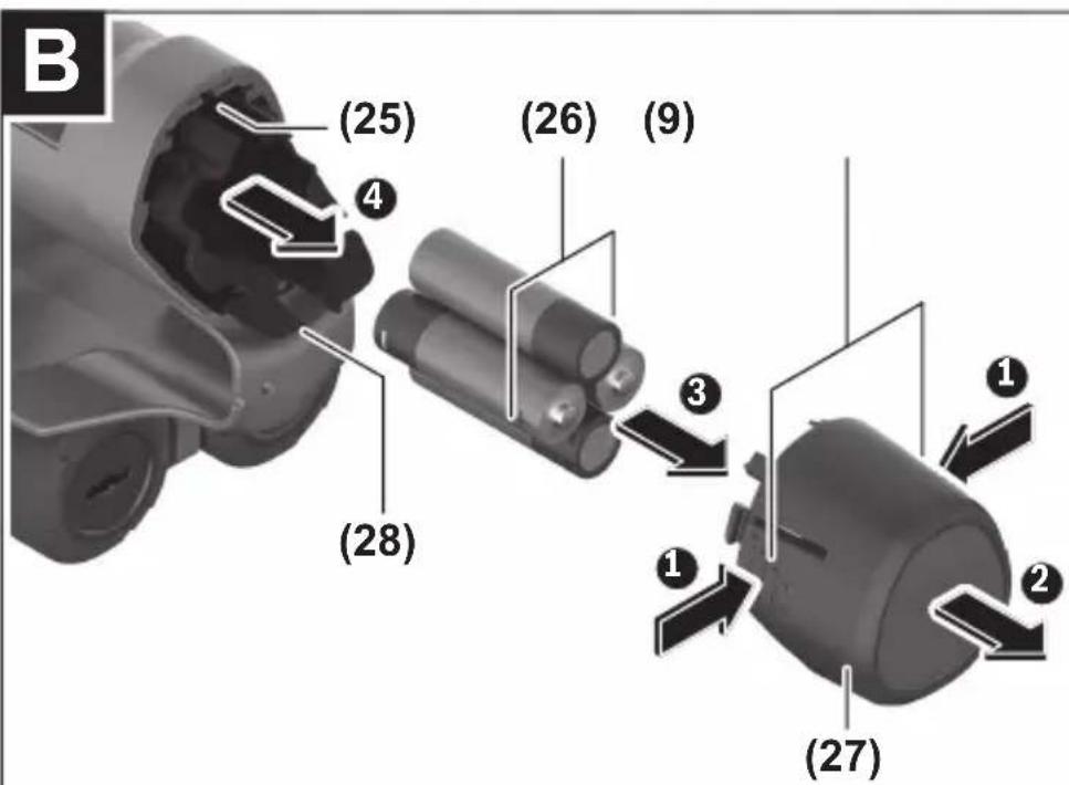
(26) Non-rechargeable batteries ^b)
(27) Battery adapter cap ^b)
(28) Battery adapter cover ^b)
(29) Button cell holder
(30) Button cell holder screw
(31) Button cell port
(32) Button cell
a) USB Type-C® and USB-C® are trademarks of USB Implementers Forum.
b) Accessories shown or described are not included with the product as standard. You can find the complete selection of accessories in our accessories range.
Technical Data
Universal detector D-tect 200 C Article number 3 601 K81 600 Max. object detection depth^A) - In dry concrete • Metal objects 200 mm • Other objects 80 mm - Metal objects in early age concrete 60 mm - Wooden beams in dry walls 38 mm - Objects in horizontally perforated bricks 50 mm - Objects in other supported wall types 80 mm Accuracy of object centre measurement^A) ±5 mm Accuracy of indicated object depth^A) - In dry concrete ±5 mm - In early age concrete ±10 mm Minimum distance between two neighbouring objects^A) 40 mm Accuracy of distance measurement^B) ±10 mm/m Radar sensor - Operating frequency range 1.8–5.8 GHz - Max. transmission power 0.00001 mW Inductive sensor - Operating frequency range 48–52 kHz - Max. magnetic field strength (at 10 m) 20 dBμA/m Max. altitude 2000 m Relative air humidity max. 90 % Relative air humidity max. for "live" material identifica-tion 50 % Pollution degree according to IEC 61010-1 2^c) Measuring tool power supply - Rechargeable battery (Li-ion) 10.8 V/12 V
42 | English
Universal detector D-tect 200 C
- Non-rechargeable batteries (alkaline manganese) 4 × 1.5 V LR6 (AA)(with battery adapter) Approx. operating time - Rechargeable battery (Li-ion) 6 h - Non-rechargeable batteries (alkaline manganese) 2 h Backup power supply for saving the time - Button cell CR2032 (3 V lithium battery) - Battery life approx. 12 months Weight according to EPTA-Procedure 01:2014 - With rechargeable battery 0.69–0.70 kg D) - With non-rechargeable batteries 0.64 kg Dimensions (length × width × height) 231 × 106 × 112 mm Protection ratingE) IP 5X Recommended ambient temperature during charging 0 °C to +35 °C Permitted ambient temperature during operation -10 °C to +50 °C Permitted ambient temperature during storage -20 °C to +70 °C Recommended rechargeable batteries GBA 10,8V 2.0Ah GBA 10,8V 3.0AhGBA 12V 2.0AhGBA 12V 3.0Ah Recommended chargers GAL 12... GAX 18...
A) Depends on material and size of the objects, as well as material and condition of the substrate and the selected view. The best results can be obtained in homogeneous, dry substrates. In addition, a deviation in the indicated object depth of ±0.5 mm/cm for objects deeper than 60 mm must be taken into account.
B) Depends on the material and condition of the substrate
C) Only non-conductive deposits occur, whereby occasional temporary conductivity caused by condensation is expected.
D) Depends on battery in use
E) The lithium-ion battery and AA1 battery adapter are not covered by IP 5X.
The serial number (20) on the type plate is used to clearly identify your measuring tool.
The accuracy and detection depth of the measuring result may be negatively affected if the condition of the substrate is unfavorable.
For the signal test, which checks whether the measuring tool is receiving a faulty signal, the conductivity criterion and level are used that are defined in ETSI TS 103 361 (V1.1.1) section 9.4.1 for an object depth of d = 60 mm.
Operation
▶ Protect the measuring tool from moisture and direct sunlight.
▶ Do not expose the measuring tool to any extreme temperatures or variations in temperature. In case of large variations in temperature, leave the measuring tool to adjust to the ambient temperature before switching it on. The accuracy of the measuring tool and the functionality of the display may be compromised if exposed to extreme temperatures or variations in temperature.
- Avoid hard knocks to the measuring tool or dropping it. After severe external influences and in the event of abnormalities in the functionality, you should have the measuring tool checked by an authorised Bosch after-sales service agent.
▶ Certain ambient conditions fundamentally impair the measuring results. These include, e.g. the proximity of devices that generate strong electric, magnetic or electromagnetic fields, moisture, metal building materials, foil-laminated insulation materials or conductive wallpaper or tiles. Therefore, also refer to other information sources (e.g. construction plans) before drilling, sawing or routing into walls, ceilings or floors.
▶ Hold the measuring tool by the intended gripping surface (11) only, so as not to influence the measurement.
▶ Do not attach any stickers or labels to the sensor area (19) on the rear of the measuring tool. Metal labels in particular will affect measuring results.

Do not wear gloves when taking measurements and make sure that you are properly earthed. If you are not properly earthed, the material identification of "live" wires may be impaired.

When taking measurements, avoid devices that emit strong electric, magnetic or electromagnetic fields. If possible, deactivate all tools whose radiation could interfere with the measurement and switch off the corresponding functions or tools.
44 | English
The measuring tool can be operated either with conventional non-rechargeable batteries or with a Bosch lithium-ion battery.
▶ Use only the chargers listed in the technical data. Only these chargers are matched to the lithium-ion battery of your measuring tool.
Note: The use of batteries unsuitable for your measuring tool can lead to malfunctions or damage to the measuring tool.
Note: The battery is supplied partially charged. To ensure full battery capacity, fully charge the battery in the charger before using your tool for the first time.
The lithium-ion battery can be charged at any time without reducing its service life. Interrupting the charging process does not damage the battery.
The lithium-ion battery is protected against deep discharge by the "Electronic Cell Protection (ECP)". A protective circuit switches the measuring tool off when the battery is drained.
To insert the charged battery pack (10), slide it into the battery bay (25) until you feel it engage.
To remove the battery pack (10), press the release buttons (9) and pull the battery pack out of the battery bay (25). Do not use force to do this.
It is recommended that you use alkaline manganese batteries to operate the measuring tool.
The batteries are inserted into the battery adapter.
The battery adapter is intended only for use in designated Bosch measuring tools and must not be used with power tools.
To insert the batteries, slide the receptacle (28) of the battery adapter into the battery bay (25). Place the batteries in the receptacle as shown in the picture on the cap (27). Slide the cap over the receptacle until you feel it click into place.

To remove the batteries (26), press the release buttons (9) of the cap (27) and pull off the cap. Make sure that the batteries do not fall out by holding the measuring tool with the battery bay (25) facing upwards. Remove the batteries. To remove the receptacle (28) from inside the battery bay, reach into the receptacle and pull it out of the measuring tool, applying light pressure to the side wall as you do so.
Always replace all the batteries at the same time. Only use batteries from the same manufacturer and which have the same capacity.
▶ Take the batteries out of the measuring tool when you are not using it for a prolonged period of time. The batteries can corrode and self-discharge during prolonged storage in the measuring tool.
Starting Operation
Switching on/off
▶ Before switching on the measuring tool, ensure that the sensor area (19) is dry. If necessary, use a cloth to dry the measuring tool.
▶ If the measuring tool has been exposed to a significant change in temperature, leave it to adjust to the ambient temperature before switching it on.
To switch on the measuring tool, press either the on/off button (8) or the red start button (16).
To switch off the measuring tool, press the on/off button (8) again.
If no button on the measuring tool is pressed for approx. 5 minutes and the measuring tool is not moved, the measuring tool will automatically switch itself off to preserve battery life. You can change the switch-off time in the main menu (see "Main Menu", page 54).
Overview of the measuring modes
The measuring tool has the following measuring modes:
\- : For detecting objects in walls, floors and ceilings,
\- : For detecting leaks,
\- : For measuring distances.
You can change the measuring mode in the main menu (see "Main Menu", page 54).
Measuring Mode
How it Works
The measuring tool checks the substrate of the sensor area. Objects that are different from the material of the wall are detected.
If multiple objects are located over each other in the wall, the display will indicate the object whose surface is nearest to the measuring tool.
Detectable objects
\- Plastic pipes (e.g. water-filled plastic pipes, such as underfloor or wall heating pipes, etc. with a diameter of at least 10 mm, or empty pipes with a diameter of at least 20 mm in solid surrounding material)
– Electrical cables (regardless of whether live or not)
46 | English
– Three-phase power cables (e.g. to oven)
– Low-voltage cables (e.g. doorbell, telephone, network, smart home)
- All types of metal pipe, rod or carrier (e.g. steel, copper, aluminium)
- Reinforcing steel
- Wooden beams
- Cavities
Special measuring cases
Unfavourable conditions fundamentally impair the measuring result:
- Multi-layered walls
- Empty plastic pipes and wooden beams in cavities and lightweight partition walls
- Objects lying at an angle in the wall
- Metal surfaces and moist areas; if in a wall, these may be displayed as objects under certain conditions (e.g. high moisture content).
Please note that concrete requires several months to dry out completely.
– Cavities in a wall; these may be displayed as objects
- Proximity to devices that generate strong magnetic or electromagnetic fields, e.g. mobile phone base stations or generators
Before drilling, sawing or routing into walls, refer to other sources of information to ensure that you eliminate hazards. Since the measuring results can be influenced by ambient conditions or the wall material, there may be a hazard even though the indicator does not indicate an object within the sensor range.
Change the wall type
Always set the appropriate wall type for best possible measuring results. To do this, repeatedly press the left-hand (14) or right-hand arrow button (7) until the required wall type is displayed. Press the red start button (16) to accept the selection.
The maximum measuring depth is 8 cm. Any deviations from this value are described in the individual wall types and views.
Wall Type
The wall type is suitable for most applications in solid masonry or other homogeneous materials. It displays plastic pipes and metal objects as well as electrical and other cables. Cavities in masonry or empty plastic pipes with a diameter of less than 2 cm may not be displayed.
Wall Type
The wall type is suitable for applications in dry concrete. It displays plastic pipes and metal objects as well as electrical and other cables. Empty plastic pipes with a diameter of less than 2 cm may not be displayed.
When selecting the wall type, you can additionally set the maximum measuring depth between 8 cm and 20 cm.
Wall Type
The wall type is suitable for detecting timber joists and metal supports, as well as electrical and other cables in drywalls (wood, plasterboard, etc.). Filled plastic pipes and wooden beams appear identical on the display. Empty plastic pipes are not recognised.
Wall Type
The wall type is especially suitable for detecting metal, metal-composite and water-filled plastic pipes and electrical cables. Empty plastic pipes are not displayed.
Wall Type
The wall type is especially suitable for applications in vertically perforated bricks. Vertically perforated bricks are bricks with many small, mostly vertical, cavities. It displays metal objects, electrical and other cables, as well as water-filled plastic pipes. Cavities or empty plastic pipes may not be displayed.
Wall Type
The wall type is especially suitable for applications in horizontally perforated bricks. Horizontally perforated bricks are bricks with a few, mostly horizontal, cavities. It displays flat lying metal objects, electrical and other cables, as well as water-filled plastic pipes up to a maximum measuring depth of 5 cm. Cavities or empty plastic pipes may not be displayed.
Wall Type
The wall type is especially suitable for applications in concrete which has not yet fully cured and dried. Metal objects are displayed up to a maximum measuring depth of 6 cm. Plastic pipes and cables may not be displayed. A distinction between live and voltage-free conductors is not possible.
Please observe that concrete requires several months to cure and dry completely.
Change the view
To change the view, repeatedly press the top (17) or bottom select button (12) until the required view is displayed. Press the red start button (16) to accept the selection.
48 | English
natural_image
Concentric circular target with concentric rings and crosshairs, displayed in a mobile app interface (no readable text or symbols on the target itself)
In the , a first measuring result is already displayed without moving the measuring tool over the substrate. It is therefore particularly suitable for measurements in corners or narrow places. The maximum measuring depth is 6 cm. Objects found are displayed with material properties, if available, but without depth information.
Whenever possible, you should also move the measuring tool over the substrate in the to ensure the best possible measurements. Locating plastic pipes and timber joints is particularly limited without moving the measuring tool.
Measuring indicator:
If no object is found, only the outer circle will appear on the display and it will light up green.
If there is an object nearby, the outer circle will light up red. The closer the measuring tool is to an object, the more the deflection in the measuring indicator (number of circles) will increase. The deflection decreases when the measuring tool moves away from the object.
Orientation arrows are displayed if the signal strength is sufficient. To specifically locate the object's centre, move the measuring tool in the direction of the orientation arrows. Above the centre of an object, the measuring indicator will exhibit maximum deflection, and with sufficient signal strength, a centre cross is displayed. The colour coding for the material property is identical to that in the .
If the orientation arrows or the centre cross are not displayed, an object may nevertheless be located in the immediate vicinity.
text_image
Concrete
2.0cm
live
The offers the best possible measuring results and the maximum measuring depths. The detected objects are displayed over the measuring path with depth information and, if available, with material properties.
Measuring process:
- Place the measuring tool on the substrate and move it over the substrate in the direction of travel. The measuring results are shown on the display after a minimum measuring path of approx. 10 cm.
- Always move the measuring tool in a straight line while applying light pressure over the substrate so that the wheels remain in contact with the wall.
- To obtain optimum measuring results, move the measuring tool slowly over the entire area to be checked and observe the measuring results as you move the tool back. The measuring path should be at least 40 cm.
- You can start a new measurement at any time by pressing the red start button (16).
- If you lift the measuring tool away from the wall during the measuring process, the last measuring result obtained remains on the display. The measurement is restarted when the device is set down or moved.
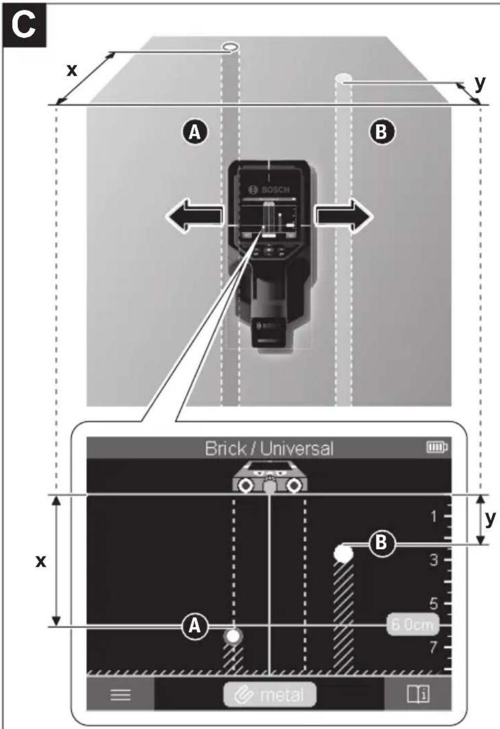
The tool's function allows for reliable detection of the nearest edges of objects that run transverse to the direction of movement of the measuring tool (see figure C). For this reason, always move crosswise over the area to be checked.
To locate objects, moving the measuring tool once over the measuring path is sufficient. To identify the exact location of a detected object and to mark the object, move the measuring tool back over the measuring path.
The direction of a found object in a wall can be determined by moving along several offset measuring paths one after another.
50 | English
Measuring indicator:
If no object was detected in the sensor range, the dashed lines and the centre line are completely green.
If an object was detected under the sensor, it will appear in the sensor range between the two dashed lines of the display. The two dashed lines and the centre line are at least partially red.
In the right-hand depth scale, depending on the setting, the object depth to the nearest edge of the found object or the maximum permissible drilling depth is displayed. You can change between the two depths in the main menu. Always use the display of the maximum permissible drilling depth when using the measuring tool for the corresponding application.
The representation of the properties of detected objects in the display can deviate from the actual object properties. In particular, very thin objects appear thicker on the display. Larger, cylindrical objects (e.g. plastic pipes or water pipes) may appear narrower on the display than they actually are.
Depending on type and depth of the object, identification of the material is possible. The type of material can be recognised by the colour of the object in the display:
Yellow: Live object
Blue: Magnetic metal (e.g. reinforcing steel)
Turquoise: Non-magnetic metal (e.g. copper pipe)
White: Non-metal material (e.g. wood, plastic)
Grey: Material property unknown
Information on material identification:
- For live objects, no further characteristic is displayed.
- Three-phase mains wiring may not be detected as live conductors.
- At a relative humidity above 50% , detecting the "live" property may be limited.
Marking objects:
- If you want to mark a found object on the substrate, move the measuring tool so that the object is centred on the centre line in the display. Use the upper marking aid (1) as well as the left-hand and right-hand marking aid (5) to make a mark on the substrate. The centre of the object is located at the intersection point of the drawn markers.
- Alternatively, move the measuring tool to the left or right until the found object is centered on one of the two dashed lines in the display. Then it is located under the corresponding outer edge of the measuring tool. Draw a line along this outer edge on the substrate and mark the position of the corresponding lateral marking aid (5) on this line. This is the centre of the object.
\- The direction of a found object in a wall can be marked by moving along several offset measuring paths one after another and connecting the respective markings.

text_image
Concrete
1
2
3
4
5
6
7
i
The indicates the signal strength at each measuring point in combination with the object depth. The is a variant of the . It displays signal strengths instead of object symbols. The maximum signal strength represents the upper edge of the objects.
The can be used to locate closely adjacent objects and to better assess complicated material structures. Weaker objects and objects in a row can also be found under certain circumstances.
Follow the instructions on the measuring process in .

text_image
Concrete
Bosch Power Tools 1 609 92A 7LD | (06.05.2022)
52 | English
The displays the signal strength at each measuring point without information on the object depth.
The can be used to locate closely adjacent objects and to better assess complicated material structures based on the signal path.
Follow the instructions on the measuring process in .
Measuring Mode

text_image
Leakage Detection
In this measuring mode, the relative material moisture of the surface is displayed. It is therefore suitable for locating the point of maximum material moisture and thus a possible leakage.
Different materials on the surface, flat lying objects and inhomogeneities in the substrate (such as joints) can distort the result.
Measuring Mode
In this measuring mode, you can measure distances on the wall. It is only possible to take this measurement in a straight line in the direction of travel of the wheels.
Place the measuring tool onto the wall at the starting point for the measurement. The reference point of the measurement is always the top marking aid (1). If necessary, press the red start button (16) to delete the displayed measured value and to start a new measurement.
Move the measuring tool over the wall in a straight line in the required direction while applying uniform pressure. The distance to the starting point is continuously measured.
The measured value shown on the display is the distance to the starting point for the current measurement, not the total distance travelled (as you move the tool back towards the starting point, the measured value will be smaller).
If a required distance is to be marked on the wall, mark it using the top marking aid (1).
Save/transfer the measuring results
Saving Measuring Results as an Image
A screenshot function is available in the . This enables you to save measurement results as an image in order to document them or to analyse them later on. Measure the required range as usual. Then press the screenshot button (13).
If an SD card is inserted, the images are saved on the card. Otherwise, the images are stored in the internal memory of the measuring tool and can be transferred via the USB Type-C® interface.
Data transfer via USB Type-C® interface
Open the flap for the USB Type-C® port (4). Connect the USB Type-C® port of the switched-off measuring tool to your PC via the USB Type-C® cable (23).
Switch on the measuring tool using the on/off button (8).
Open the file browser on your PC and select the BOSCH D-tect 200 C drive. The saved files can be copied from the internal memory of the measuring tool, moved to your PC or deleted.
As soon as you have completed the required operation, disconnect the drive following the standard procedure.
Note: Always disconnect the drive from the operating system of the PC first (eject drive), as failure to do so may damage the internal memory of the measuring tool.
Then switch off the measuring tool using the on/off button (8). Remove the USB Type-C® cable (23). Close the flap for the USB Type-C® port (4) to protect it from dust or splashes.
Note: Use the USB Type-C® interface to connect the measuring tool to a PC only. The measuring tool may be damaged if connected to other devices.
Note: The USB Type-C® interface can only be used for data transfer. Rechargeable batteries or other devices cannot be charged by this interface.
Data Transfer via SD Card
If an SD card is inserted in the measuring tool, images are automatically stored on the card when saved, not in the internal memory of the measuring tool.
To insert the SD card, open the flap of the slot (3). Pay attention to the correct orientation when inserting the SD card. Close the flap of the slot (3) to protect it from dust or splashes.
Note: Switch off the measuring tool before removing the SD card. Otherwise, the SD card may be damaged.
54 | English
Main Menu
To access the main menu, press the left-hand function button (15).
- To scroll through a menu: Press the up (17) or down (12) arrow buttons.
- To switch to a submenu: Press the red start button (16) or the right-hand arrow button (7).
- To confirm a selected menu option: Press the red start button (16).
- To change a menu option using the on/off switch: Press either the red start button (16), the left-hand (14) or the right-hand arrow button (7). This will also save the menu option.
- To go back to the next highest menu: Press the left-hand function button (15) under the back arrow.
- To leave the main menu and go back to measuring: Press the right-hand function button (6) under the Home symbol.
-
Set the required measuring mode (see "Overview of the measuring modes", page 45). Once you have made your selection, the measuring tool will directly switch to the selected measuring mode.
In the measuring mode, you can also set the wall type suitable for the planned measurement and the view for the measurements.
-
- : Switch on/off the ruler for the measuring modes (with the exception of the ) and for the . Using the ruler, you can determine the distance between object centres, for example. Press the right-hand function button (6) to set the ruler to zero.
- : Choose between the indicator for the and the maximum permissible .
- : Set the brightness level of the display backlight.
- : Switch the audio signal on or off. When the audio signal is switched on, an audio signal sounds every time a button is pressed and every time an object is found within the sensor range.
- : Choose the settings (e.g. wall type, view, ruler) that the measuring tool starts up when it is switched on. Choose between applying the settings from the last time the tool was switched off and personalised basic settings (these are the current settings in the main menu).
- : Choose the time interval after which the measuring tool will switch off automatically if it is not in use.
- : Select the language used in the display.
- : You can set the date and time for saving images and select the date and time format. Change the button cell (see "Inserting/changing the button cell (see figure D)", page 56) when the time and date can no longer be saved.
- : Select the unit of measurement for the measuring indicators.
- : You can reset all of the menu options to factory settings. Simultaneously, all of the saved images will be permanently deleted.
-
Here you will find device information, such as the installed software version and legal information.
If required, you can update the software of the measuring tool:
- Download the update file to the SD card from www.wallscanner.com.
- Insert the SD card into the measuring tool (see "Data Transfer via SD Card", page 53).
- The update process starts automatically as soon as the SD card is inserted and the measuring tool is switched on. A corresponding indicator appears in the display.
- When the update is complete, the measuring tool is automatically restarted.
Note: Switch off the measuring tool before removing the SD card. Otherwise, the SD card may be damaged.
Errors – Causes and Corrective Measures
Cause Corrective measures
Measuring tool cannot be switched on.
Battery pack or batteries empty Charge the battery pack or change the batteries. Measuring tool cannot be connected to a PC via USB. Measuring tool not recognised by PC. Check whether the driver on your PC is up to date. It may be necessary to have a newer operating system version on your PC. USB Type-C® port (4) or USB cable (23) faulty Check whether the measuring tool can be connected to a different USB cable or a different PC. If it cannot, send the measuring tool to an authorised Bosch after-sales service centre.
Bosch Power Tools 1 609 92A 7LD | (06.05.2022)
56 | English
If the info/help symbol is shown on the display above the right-hand function button (6), you can access context-related information and help by pressing the right-hand function button (available when changing wall type and view, as well as in all measuring modes of the and in the ).
Maintenance and Service
Maintenance and Cleaning
▶ Check the measuring tool before each use. If the measuring tool is visibly damaged or parts have become loose inside the measuring tool, safe function can no longer be ensured.
Always keep the measuring tool clean and dry to ensure optimum, safe operation.
Never immerse the measuring tool in water or other liquids.
Wipe off any dirt using a dry, soft cloth. Do not use any detergents or solvents.
Only store and transport the measuring tool in the protective bag (21) or the case (24).
If the measuring tool needs to be repaired, send it off in the protective bag (21) or the case (24).
If the wheels (2) are worn, they must be replaced. The wheels are available in the spare parts range of Bosch.
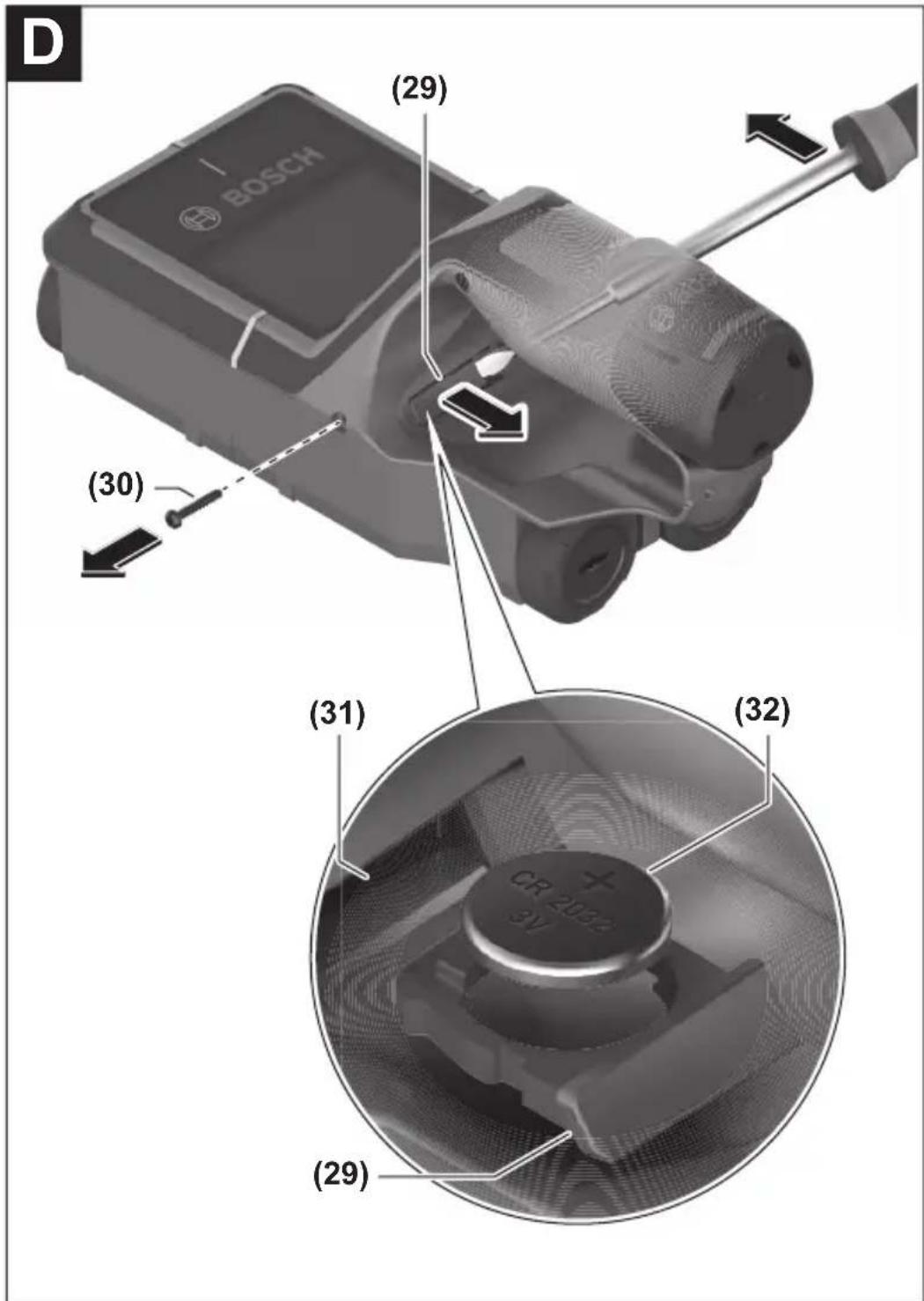
To be able to save the time on the measuring tool, a button cell (32) must be used.
Unscrew the screw (30) on the button cell holder (29). Pull the button cell holder out of the button cell port (31) with an auxiliary tool (e.g. a flat-head screwdriver).
Remove the empty button cell (32) and insert a new button cell. Ensure that the polarity is correct according to the illustration on the button cell holder (the positive terminal of the button cell must be facing upwards).
With the button cell fitted, slide the button cell holder (29) into the port (31). Ensure that the button cell holder is inserted correctly and fully, as otherwise protection from dust and splashes is no longer guaranteed.
Retighten the screw (30) on the button cell holder (29).
After-Sales Service and Application Service
Our after-sales service responds to your questions concerning maintenance and repair of your product as well as spare parts. You can find explosion drawings and information on spare parts at: www.bosch-pt.com
The Bosch product use advice team will be happy to help you with any questions about our products and their accessories.
In all correspondence and spare parts orders, please always include the 10-digit article number given on the nameplate of the product.
Great Britain
Robert Bosch Ltd. (B.S.C.)
P.O. Box 98
Broadwater Park
North Orbital Road
Denham Uxbridge
UB 9 5HJ
At www.bosch-pt.co.uk you can order spare parts or arrange the collection of a product in need of servicing or repair.
Tel. Service: (0344) 7360109
E-Mail: boschservicecentre@bosch.com
You can find further service addresses at:
www.bosch-pt.com/serviceaddresses
Transport
The recommended lithium-ion batteries are subject to legislation on the transport of dangerous goods. The user can transport the batteries by road without further requirements.
When shipping by third parties (e.g.: by air transport or forwarding agency), special requirements on packaging and labelling must be observed. For preparation of the item being shipped, consulting an expert for hazardous material is required.
Dispatch battery packs only when the housing is undamaged. Tape or mask off open contacts and pack up the battery in such a manner that it cannot move around in the packaging. Please also observe the possibility of more detailed national regulations.
Disposal

Measuring tools, rechargeable/non-rechargeable batteries, accessories and packaging should be sorted for environmental-friendly recycling.

Do not dispose of the measuring tools or battery packs/batteries with household waste.
58 | English
Only for EU countries:
According to the Directive 2012/19/EU on waste electrical and electronic equipment and its transposition into national law, measuring tools that are no longer usable, and, according to the Directive 2006/66/EC, defective or drained batteries must be collected separately and disposed of in an environmentally correct manner.
If disposed incorrectly, waste electrical and electronic equipment may have harmful effects on the environment and human health, due to the potential presence of hazardous substances.
Only for United Kingdom:
According to Waste Electrical and Electronic Equipment Regulations 2013 (2013/3113) and the Waste Batteries and Accumulators Regulations 2009 (2009/890), measuring tools that are no longer usable must be collected separately and disposed of in an environmentally friendly manner.
Battery packs/batteries:
Li-ion:
Please observe the notes in the section on transport (see "Transport", page 57).
Table des matières
Consignes de sécurité....Page 61
Description des prestations et du produit ...... Page 63
Utilisation conforme...... Page 63
Éléments constitutifs.... Page 64
Caractéristiques techniques...... Page 65
Utilisation Page 67
Alimentation en énergie de l'appareil de mesure...... Page 68
Fonctionnement avec accu Lithium-Ion (voir figure A) ...... Page 68
Fonctionnement avec piles (voir figure B) ...... Page 69
Mise en marche ...... Page 69
Mise en marche / arrêt ...... Page 69
Vue d'ensemble des modes de mesure.... Page 70
Mode de mesure ...... Page 70
Fonctionnement......Page 70
Changement de type de mur ...... Page 71
Type de mur ...... Page 71
Type de mur ...... Page 71
Type de mur ...... Page 72
Type de mur ...... Page 72
Type de mur ...... Page 72
Type de mur ...... Page 72
Type de mur Page 72
Changement de vue...... Page 73
Page 73
Page 74
Page 76
Page 77
Mode de mesure ...... Page 77
Mode de mesure ...... Page 78
Mémorisation/transfert de résultats de mesure ...... Page 78
60 | Français
Mémorisation de résultats de mesure comme image.... Page 78
Transmission de données via l'interface USB Type-C®...... Page 78
Transmission de données via la carte SD...... Page 79
Menu principal Page 79
Navigation dans le menu...... Page 79
Options de menu...... Page 80
Mise à jour du logiciel de l'appareil de mesure ...... Page 81
Défauts – Causes et remèdes ...... Page 81
Entretien et Service après-vente Page 82
Nettoyage et entretien.... Page 82
Mise en place/remplacement de la pile bouton (voir figure D) ...... Page 82
Service après-vente et conseil utilisateurs ...... Page 82
Vous trouverez d'autres adresses du service après-vente sous : ...... Page 83
Transport Page 83
Élimination des déchets.... Page 84
Seulement pour les pays de l'UE : ...... Page 84
Accus/piles : Page 84
Français
Consignes de sécurité

Prière de lire et de respecter l'ensemble des instructions. En cas de non-respect des présentes instructions, les fonctions de protection de l'appareil de mesure risquent d'être altérées. BIEN CONSERVER LES PRÉSENTES INSTRUCTIONS.
▶ Ne confiez la réparation de l'appareil de mesure qu'à un réparateur qualifié utilisant uniquement des pièces de rechange d'origine. La sécurité de l'appareil de mesure sera ainsi préservée.
▶ Ne faites pas fonctionner l'appareil de mesure en atmosphère explosive, en présence de liquides, gaz ou poussières inflammables. L'appareil de mesure peut produire des étincelles susceptibles d'enflammer les poussières ou les vapeurs.
▶ N'ouvrez pas l'accu. Risque de court-circuit.
Si l'accu est endommagé ou utilisé de manière non conforme, des vapeurs peuvent s'échapper. L'accu peut brûler ou exploser. Ventilez le local et consultez un médecin en cas de malaise. Les vapeurs peuvent entraîner des irritations des voies respiratoires.
En cas d'utilisation inappropriée ou de défectuosité de l'accu, du liquide inflammable peut suinter de l'accu. Évitez tout contact avec ce liquide. En cas de contact accidentel, rincez abondamment à l'eau. Si le liquide entre en contact avec les yeux, consultez en plus un médecin dans les meilleurs délais. Le liquide qui s'échappe de l'accu peut causer des irritations ou des brûlures.
Les objets pointus comme un clou ou un tournevis et le fait d'exercer une force extérieure sur le boîtier risque d'endommager l'accu. Il peut en résulter un court-circuit interne et l'accu risque de s'enflammer, de dégager des fumées, d'exploser ou de surchauffer.
Lorsque l'accu n'est pas utilisé, le tenir à l'écart de tout objet métallique (trombones, pièces de monnaie, clés, clous, vis ou autres objets de petite taille) susceptible de créer un court-circuit entre les contacts. Le court-circuitage des contacts d'un accu peut causer des brûlures ou causer un incendie.
▶ N'utilisez l'accu qu'avec des produits du fabricant. Tout risque de surcharge dangereuse sera alors exclu.
62 | Français
▶ Ne chargez les accus qu'avec des chargeurs recommandés par le fabricant. Un chargeur conçu pour un type d'accu bien spécifique peut provoquer un incendie lorsqu'il est utilisé pour charger d'autres accus.


Conservez la batterie à l'abri de la chaleur, en la protégeant p. ex. de l'ensoleillement direct, du feu, de la saleté, de l'eau et de l'humidité. Il existe un risque d'explosion et de courts-circuits.
Du fait de sa conception, l'appareil de mesure ne peut pas garantir une sécurité absolue. Afin d'exclure tout danger, prenez certaines précautions avant d'effectuer des travaux de perçage, de sciage ou de fraisage dans les murs, plafonds ou sols en consultant d'autres sources d'information telles que les plans de construction, les photos de la phase de construction etc. Les conditions environnantes (humidité de l'air, etc.) ou la présence à proximité d'autres appareils électriques risquent d'altérer la précision de l'appareil de mesure. La structure ou l'état des murs (par ex. humidité, matériaux de construction métalliques, papiers peints conducteurs, matériaux isolants, carreaux) ainsi que le nombre, le type, la dimension et la position des objets peuvent fausser les résultats de mesure.
En présence de conduites de gaz dans le bâtiment, vérifiez après avoir effectué des travaux sur les murs, les plafonds ou les sols qu'aucune conduite de gaz n'a été endommagée.
Éteignez tous les consommateurs électriques et mettez hors tension les câbles électriques avant de percer, scier ou fraiser dans des murs, des plafonds ou des sols. Vérifiez au terme des travaux que les objets qui ont été fixés ne se trouvent pas sous tension.
Lors de la fixation d'objets sur des cloisons sèches, assurez-vous que la cloison et les éléments de fixation sont capables de supporter le poids de l'objet, particulièrement lors de la fixation sur une ossature.


AVERTISSEMENT


Assurez-vous de ne jamais laisser la pile bouton à la portée des enfants. Les piles boutons sont dangereuses.
Les piles boutons ne doivent en aucun cas être ingérées ou introduites dans des ouvertures corporelles. En cas de suspicion d'ingestion d'une pile bouton ou d'introduction d'une pile dans une autre ouverture corporelle, consultez immédiatement un médecin. L'ingestion d'une pile bouton peut, au bout de seulement 2 heures, provoquer des brûlures graves et même entraîner la mort.
Lors d'un changement de pile bouton, veuillez respectez les règles et précautions d'usage. Il y a sinon risque d'explosion.
Veuillez n'utiliser que le type de pile bouton indiqué dans la présente notice d'utilisation. N'utilisez aucune autre pile bouton ni aucune autre source d'alimentation électrique.
N'essayez pas de recharger la pile bouton ou de la court-circuiter. La pile bouton risque alors de fuir, d'exploser, de brûler et de blesser des personnes.
▶ Retirez les piles boutons déchargées et éliminez-les en respectant la législation en vigueur. Les piles boutons déchargées peuvent se mettre à fuir et détériorer le produit ou blesser des personnes.
▶ Ne surchauffez pas la pile bouton et ne la jetez pas dans le feu. La pile bouton risque alors de fuir, d'exploser, de brûler et de blesser des personnes.
N'endommagez-pas la pile bouton et n'essayez pas de l'ouvrir. La pile bouton risque alors de fuir, d'exploser, de brûler et de blesser des personnes.
▶ Ne mettez pas une pile bouton endommagée en contact avec de l'eau. Le lithium qui s'échappe peut produire de l'hydrogène en réagissant avec l'eau. Il y a alors risque d'incendie, d'explosion ou de blessure de personnes.
N'utilisez plus l'appareil de mesure quand il n'est plus possible de fermer correctement et complètement le support de la pile bouton. Retirez la pile bouton et faites réparer l'appareil de mesure.
Description des prestations et du produit
Référez-vous aux illustrations qui se trouvent au début de la notice d'utilisation.
L'appareil de mesure est conçu pour détecter des objets cachés dans des murs, plafonds et sols. Suivant le matériau et la nature du support, il est possible de reconnaître des objets métalliques, poutres en bois, tuyaux en matière plastique, conduites et câbles.
L'appareil de mesure respecte les valeurs limites des normes indiquées dans la déclaration de conformité. La déclaration de conformité UE est disponible sous http://eu-doc.bosch.com/.
C'est sur cette base que doit être prise la décision d'autoriser ou non l'utilisation de l'appareil de mesure p. ex. dans les hôpitaux, centrales nucléaires et à proximité d'aéroports et de stations de radiocommunication mobile.
L'appareil de mesure est conçu pour une utilisation en intérieur et en extérieur.
64 | Français
Éléments constitutifs
La numérotation des éléments de l'appareil se réfère à la représentation de l'appareil de mesure sur la page graphique.
(1) Repère supérieur
(2) Roulette
(3) Logement pour carte microSD
(4) Prise USB Type-C ^® a)
(5) Repère côté gauche ou droit
(6) Touche de fonction de droite
(7) Touche flèche vers la droite
(8) Touche Marche/Arrêt
(9) Touche de déverrouillage accu/adaptateur piles ^b)
(10) Accu ^b)
(11) Surface de préhension
(12) Touche Flèche vers le bas
(13) Touche Capture d'écran
(14) Touche Flèche vers la gauche
(15) Touche de fonction de gauche
(16) Touche Start rouge
(17) Touche Flèche vers le haut
(18) Écran
(19) Zone de détection
(20) Numéro de série
(21) Housse de protection ^b)
(22) Dragonne
(23) Câble USB Type-C®
(24) Coffret ^b)
(25) Logement d'accu
(26) Piles ^b)
(27) Couvercle de l'adaptateur piles ^b)
(28) Corps de l'adaptateur piles ^b)
Français | 65
(29) Support de pile bouton
(30) Vis du support de pile bouton
(31) Logement de pile bouton
(32) Pile bouton
a) USB Type-C® et USB-C® sont des marques déposées de l'USB Implementers Forum.
b) Les accessoires décrits ou illustrés ne sont pas tous compris dans la fourniture. Vous trouverez les accessoires complets dans notre gamme d'accessoires.
Caractéristiques techniques
Détecteur universel D-tect 200 C Référence 3 601 K81 600 Profondeur de détection maxiA) - dans le béton sec • Objets métalliques 200 mm • Autres objets 80 mm - Objets métalliques dans le béton frais 60 mm - Ossatures en bois dans cloisons sèches 38 mm - Objets dans brique à alvéoles horizontales 50 mm - Objets dans autres types de mur supportés 80 mm Précision de détection du centre d'un objetA) ±5 mm Précision de la profondeur d'objet affichéeA) - dans le béton sec ±5 mm - dans le béton frais ±10 mm Distance minimale entre deux objets voisinsA) 40 mm Précision de la mesure de distancesB) ±10 mm/m Capteur radar - Plage de fréquences de fonctionnement 1,8–5,8 GHz - Puissance d'émission maxi 0,00001 mW Capteur inductif - Plage de fréquences de fonctionnement 48–52 kHz - Intensité maximale du champ magnétique (à 10 m) 20 dBμA/m
66 | Français
Détecteur universel D-tect 200 C
Altitude d’utilisation maxi 2 000 m Humidité d’air relative maxi 90 % Humidité d’air relative maxi pour détection de matériaux « sous tension » 50 % Degré d’encrassement selon CEI 61010-1 2 c) Alimentation électrique de l’appareil de mesure – Accu (Lithium-ion) 10,8 V/12 V – Piles (alcalines au manganèse) 4 × 1,5 V LR6 (AA) (avec adaptateur piles) Autonomie approx. – Accu (Lithium-ion) 6 h – Piles (alcalines au manganèse) 2 h Alimentation de sauvegarde pour mémorisation de l’heure – Pile bouton CR2032 (pile au lithium de 3 V) – Durée de vie approx. de la pile 12 mois Poids suivant EPTA-Procedure 01:2014 – avec accu 0,69–0,70 kg d) – avec piles 0,64 kg Dimensions (longueur × largeur × hauteur) 231 × 106 × 112 mm Indice de protectionE) IP 5X Températures ambiantes recommandées pour la charge 0 °C ... +35 °C Températures ambiantes autorisées pour l’utilisation –10 °C ... +50 °C Températures ambiantes autorisées pour le stockage –20 °C ... +70 °C Accus recommandés GBA 10,8V 2.0AhGBA 10,8V 3.0AhGBA 12V 2.0AhGBA 12V 3.0Ah
Détecteur universel D-tect 200 C
Chargeurs recommandés GAL 12...
GAX 18...
A) Dépend du matériau, de la taille des objets, de l'état du support et de la vue sélectionnée. Les meilleurs résultats sont obtenus dans des supports homogènes et secs. Il convient en plus de prendre en compte une imprécision ±0,5 mm/cm sur la profondeur affichée pour les objets enfouis de plus de 60 mm.
B) selon le type de matériau et l'état du support
C) N'est conçu que pour les salissures/saletés non conductrices mais supporte occasionnellement la conductivité due aux phénomènes de condensation.
D) Dépend de l'accu utilisé
E) L'accu Lithium-Ion et l'adaptateur piles AA1 sont exclus de la protection IP 5X.
Pour une identification précise de votre appareil de mesure, basez-vous sur le numéro de série (20) inscrit sur la plaque signalétique.
Dans les cas défavorables, la précision de mesure peut être moins bonne et la profondeur maximale de détection plus faible que ce qui est indiqué.
Pour le test récepteur qui évalue l'influence d'un signal parasite sur l'appareil de mesure, il a été utilisé le critère et le niveau de performance définis dans la spécification ETSI TS 103 361 (V1.1.1) chapitre 9.4.1 avec une profondeur d'objet d = 60 mm.
Utilisation
Protégez l'appareil de mesure contre l'humidité, ne l'exposez pas directement aux rayons du soleil.
N'exposez pas l'appareil de mesure à des températures extrêmes ou de brusques variations de température. S'il est exposé à d'importants variations de température, laissez-le revenir à la température ambiante avant de le remettre en marche. Des températures ou variations de température extrêmes peuvent altérer la précision de l'appareil de mesure et de l'affichage.
Évitez les chocs ou les chutes de l'appareil de mesure. Après avoir exposé l'appareil de mesure à des conditions extérieures extrêmes ou en cas de détection d'un fonctionnement anormal de sa part, faites-le contrôler dans un point de service après-vente Bosch agréé.
La précision de mesure peut être altérée par certaines conditions environnantes. Les sources de perturbation possibles sont par ex. les appareils produisant des champs électriques, magnétiques ou électromagnétiques intenses qui se trouvent à proximité, l'humidité, les matériaux de construction métalliques, les matériaux isolants à feuille d'aluminium ou les papiers peints et carrelages
68 | Français
conducteurs. Avant de percer, scier ou réaliser des saignées dans des murs, plafonds ou sols, consultez toutes sources d'information disponibles (par ex. les plans de construction).
Pour ne pas fausser les mesures, tenez l'appareil de mesure au niveau des surfaces de préhension (11) prévues.
N'apposez pas d'autocollants ou étiquettes dans la zone de détection (19) au dos de l'appareil de mesure. Les étiquettes métalliques risquent notamment de fausser les résultats de mesure.

Ne portez pas de gants pendant la mesure et veillez à une mise à la terre suffisante. Dans le cas d'une mise à la terre insuffisante, la détection de câbles électriques sous tension risque d'être altérée.

Évitez pendant la mesure la proximité d'appareils qui génèrent de forts champs électriques, magnétiques ou électromagnétiques.
Dans la mesure du possible, désactivez sur ces appareils les fonctions dont le rayonnement peut perturber la mesure ou bien éteignez totalement les appareils.
Alimentation en énergie de l'appareil de mesure
L'appareil de mesure est conçu pour fonctionner avec des piles du commerce ou un accu Lithium-ion Bosch.
N'utilisez que les chargeurs indiqués dans les Caractéristiques techniques. Ces chargeurs sont les seuls à être adaptés à l'accu Lithium-lon de votre appareil de mesure.
Remarque : L'utilisation d'accus non conçus pour votre appareil de mesure peut entraîner des dysfonctionnements ou endommager l'appareil de mesure.
Remarque : L'accu est fourni partiellement chargé. Pour obtenir les performances maximales, chargez l'accu jusqu'à sa pleine capacité avant la première utilisation.
L'accu Lithium-ion peut être rechargé à tout moment, sans risquer de réduire sa durée de vie. Le fait d'interrompre le processus de charge n'endommage pas l'accu.
L'accu Lithium-Ion est protégé contre les décharges complètes par l'électronique de protection des cellules " Electronic Cell Protection (ECP) ". Quand l'accu est déchargé, un circuit de protection désactive automatiquement l'appareil de mesure.
Pour mettre en place l'accu (10) chargé, insérez-le dans le logement d'accu (25) jusqu'à ce qu'il s'enclenche de manière audible.
Pour extraire l'accu (10), pressez les pattes de déverrouillage (9) de l'accu et sortez l'accu du logement (25). Ne forcez pas.
Il est recommandé d'utiliser des piles alcalines au manganèse.
Les piles doivent être insérées dans l'adaptateur de piles.
L'adaptateur de piles est uniquement destiné à une utilisation sur les appareils de mesure Bosch conçus à cet effet. Il n'est pas conçu pour être utilisé avec des outils électroportatifs.
Pour insérer les piles, insérez le corps (28) de l'adaptateur piles dans le logement d'accu (25). Insérez les piles dans le corps comme représenté sur l'illustration du couvercle (27). Placez le couvercle au-dessus du corps et exercez une pression jusqu'à ce qu'il s'enclenche de manière audible.

Pour retirer les piles (26), pressez les pattes de déverrouillage (9) du couvercle (27) et sortez le couvercle. Veillez ce faisant à ce que les piles ne tombent pas. Tenez pour cela l'appareil de mesure de façon à ce que le logement d'accu (25) soit orienté vers le haut. Retirez
les piles. Pour extraire le corps (28) du logement d'accu, glissez un doigt à l'intérieur du corps et sortez-le de l'appareil de mesure en exerçant une légère pression sur la paroi latérale.
Remplacez toujours toutes les piles en même temps. N'utilisez que des piles de la même marque et de même capacité.
Sortez les piles de l'appareil de mesure si vous savez qu'il ne sera pas utilisé pendant une période prolongée. Les piles risquent de se corroder et de se décharger quand l'appareil de mesure n'est pas utilisé pendant une longue durée.
Mise en marche
Mise en marche / arrêt
Avant de mettre en service l'appareil de mesure, assurez-vous que la zone de détection (19) n'est pas humide. Si nécessaire, séchez l'appareil de mesure à l'aide d'un chiffon.
Au cas où l'appareil de mesure aurait été exposé à une forte différence de température, laissez-le revenir à la température ambiante avant de le mettre en marche.
Pour mettre en marche l'appareil de mesure, appuyez sur la touche Marche/Arrêt (16) ou sur la touche Start rouge (8).
Pour arrêter l'appareil de mesure, appuyez à nouveau sur la touche Marche/Arrêt (8).
70 | Français
Si l'appareil de mesure n'est pas bougé et aucune touche n'est actionnée pendant env.
5 min, l'appareil de mesure s'arrête automatiquement afin d'économiser l'accu / les piles. Vous pouvez, si souhaité, modifier le délai de désactivation dans le menu principal (voir « Menu principal », Page 79).
Vue d'ensemble des modes de mesure
L'appareil de mesure dispose des modes de mesure suivants :
\- : pour détecter des objets dans des murs, des sols et des pla-fonds,
\- : pour mettre en évidence des fuites,
\- : pour mesurer des distances.
Vous pouvez changer de mode de mesure dans le menu principal (voir « Menu principal », Page 79).
Mode de mesure
Fonctionnement
L'appareil de mesure contrôle la présence d'objets dans le support (mur, sol ou plafond) dans sa zone de détection. Il détecte les objets constitués d'une autre matière que le mur proprement dit.
Lorsqu'il y a dans le mur plusieurs objets superposés, l'objet détecté et signalé sur l'écran est celui qui se trouve le plus près de la surface.
Objets détectables
- Conduits en plastique (p. ex. tuyaux en plastique remplis d'eau d'un chauffage par le sol, d'un chauffage mural etc., d'au moins 10 mm de diamètre ; tuyaux vides d'au moins 20 mm de diamètre dans un matériau massif)
- Câbles électriques (sous tension ou non)
- Câbles triphasés (d'une cuisinière électrique par exemple)
- Fils électriques à faibles tensions (sonnette, téléphone, réseau, Smart Home)
- Toutes sortes de tubes métalliques, tiges métalliques, supports métalliques (acier, cuivre, aluminium ou autre)
- Fers d'armature
- Ossatures en bois
- Cavités
Cas de mesure spéciaux
Le principe de fonctionnement de l'appareil fait que dans certaines situations les résultats de mesure ne sont pas toujours fiables :
- Parois constituées de plusieurs couches
- Tubes plastiques vides et poutres en bois dans les cavités et parois préfabriquées
- Objets disposés obliquement dans le mur
- Surfaces métalliques et zones humides ; elles peuvent, dans certaines circonstances (p. ex. taux d'humidité élevé), être identifiées par erreur comme étant des objets. Veuillez tenir compte du fait que le béton met plusieurs mois à sécher complètement.
- Cavités dans un mur ; elles peuvent être affichées comme des objets.
- À proximité d'appareils qui génèrent des champs magnétiques ou électromagnétiques intenses, p. ex. stations de base de radiocommunication mobile ou générateurs
Pour écarter tout risque, consultez d'autres sources d'information (plan de construction par exemple) avant d'entreprendre des travaux de perçage, sciage ou rainurage dans un mur. Étant donné que la composition du mur et certaines circonstances extérieures risquent d'influer sur les résultats de mesure, tout danger ne peut pas être exclu même si aucun objet n'est affiché dans la zone de détection.
Changement de type de mur
Pour obtenir les meilleurs résultats possibles, il est important de toujours sélectionner le bon type de mur. Actionnez pour cela la touche flèche vers la gauche (14) ou flèche vers la droite (7) jusqu'à ce que le type de mur souhaité soit affiché. Pour valider la sélection, actionnez la touche Start rouge (16).
La profondeur de mesure maximale est normalement de 8 cm. Il est indiqué ci-après pour les différents types de mur et types de vue quand elle diffère de cette valeur.
Type de mur
Le type de mur convient pour la plupart des applications dans de la maçonnerie massive ou d'autres matériaux homogènes. Il permet de détecter des tuyaux en plastique, des objets métalliques ainsi que des câbles électriques et d'autres conduits. Les cavités dans les maçonneries ou les tuyaux plastiques vides de moins de 2 cm de diamètre risquent de ne pas être détectés.
Type de mur
Le type de mur est spécialement conçu pour le béton sec. Il permet de détecter des tuyaux en plastique, des objets métalliques ainsi que des câbles électriques et d'autres conduits. Les tuyaux en plastique vides de moins de 2 cm de diamètre risquent de ne pas être détectés.
72 | Français
Pour ce type de mur, nous pouvez en plus régler la profondeur de mesure maximale entre 8 cm et 20 cm.
Type de mur
Le type de mur est approprié pour la détection d'ossatures en bois ou en métal, de câbles électriques et d'autres conduits dans des cloisons sèches (bois, plaque de plâtre, etc.). Les tuyaux en plastique remplis d'eau et les ossatures en bois donnent lieu au même affichage. Les tuyaux en plastique vides ne sont pas détectés.
Type de mur
Le type de mur est particulièrement indiqué pour la détection de tubes en métal, tubes composites métal/plastique, tuyaux en plastique remplis d'eau et câbles électriques. Les tuyaux en plastique vides ne sont pas détectés.
Type de mur
Le type de mur est spécialement conçu pour les briques alvéolées. Les briques alvéolées sont des briques dotées de nombreuses petites alvéoles généralement verticales. Ce mode de mesure permet de détecter des objets métalliques, des câbles électriques et d'autres conduits ainsi que des tuyaux en plastique remplis d'eau. Les cavités ou tuyaux en plastique vides risquent de ne pas être détectés.
Type de mur
Le type de mur est spécialement conçu pour les briques à alvéoles horizontales. Les briques à alvéoles horizontales sont des briques avec un petit nombre de grosses cavités généralement horizontales. Ce mode de mesure permet de détecter des objets métalliques orientés à l'horizontale, des câbles électriques et d'autres conduits ainsi que des tuyaux en plastique remplis d'eau enfouis jusqu'à une profondeur de 5 cm. Les cavités ou tuyaux en plastique vides risquent de ne pas être détectés.
Type de mur
Le type de mur est spécialement conçu pour le béton qui n'a pas fini de durci et qui n'est donc pas encore sec. Ce mode de mesure détecte les objets métalliques jusqu'à une profondeur de 6 cm. Les tuyaux en plastique et câbles risquent de ne pas être détectés. Aucune distinction n'est faite entre câbles sous tension et câbles hors tension.
Veuillez tenir compte du fait que le béton met plusieurs mois à durcir et à sécher complètement.
Changement de vue
Pour changer de vue, actionnez la touche flèche vers le haut (17) ou flèche vers le bas (12) jusqu'à ce que la vue souhaitée soit affichée. Pour valider la sélection, actionnez la touche Start rouge (16).
text_image
Concrete
Live
Dans la apparaît un premier résultat de mesure sans avoir à déplacer l'appareil de mesure au-dessus de la surface. Cette vue est idéale pour les mesures dans les coins ou espaces étroits. La profondeur de mesure maximale est de 6 cm. En cas de détection d'un objet, il apparaît à l'écran la nature de l'objet détecté (si elle est reconnue) mais pas sa profondeur.
Là où cela est possible, déplacez aussi dans la l'appareil de mesure au-dessus de la surface pour obtenir les meilleurs résultats possibles. Sans déplacement de l'appareil de mesure, la détection de tuyaux en plastique et d'ossatures en bois n'est pas toujours possible.
Affichage de mesure :
Si aucun objet n'est détecté, il n'apparaît sur l'écran que le cercle extérieur, de couleur verte.
Quand un objet se trouve à proximité, le cercle extérieur devient rouge. Plus l'objet est proche, plus le nombre de cercles augmente. Le nombre de cercles diminue lorsque l'appareil de mesure s'éloigne de l'objet.
Si l'intensité du signal est suffisante, il apparaît en plus des flèches d'orientation. Pour localiser le centre de l'objet, déplacez l'appareil de mesure dans la direction des flèches d'orientation. Quand l'appareil de mesure se trouve juste au centre de l'objet, le nombre de cercles est maximal et il apparaît une croix centrale si l'intensité du signal est suffi-
74 | Français
sante. La représentation de la nature de l'objet détecté par des couleurs est identique à celle de la .
Il n'est pas exclu qu'un objet se trouve tout près de l'appareil de mesure même si les flèches d'orientation et la croix centrale n'apparaissent pas à l'affichage.
text_image
Concrete
2.0cm
live
La permet d'obtenir les meilleurs résultats de mesure possibles et les profondeurs de mesure maximales. Il est indiqué sur l'écran la profondeur et, dans la mesure du possible, la nature de tous les objets détectés sur toute la distance de mesure.
Processus de mesure :
- Appliquez l'appareil de mesure contre la surface et déplacez-le au-dessus de la surface dans le sens de déplacement des roulettes. Après avoir parcouru une distance d'au moins 10 cm, les premiers résultats de mesure s'affichent sur l'écran.
- Déplacez toujours l'appareil de mesure en ligne droite en exerçant une légère pression de manière à ce que les roulettes restent bien en contact avec la surface.
- Pour obtenir des résultats de mesure corrects, déplacez l'appareil de mesure lente-
ment sur toute la surface à examiner et observez les résultats de mesure lorsque vous
revenez en arrière. La distance de mesure doit être d'au moins 40 cm.
- Vous pouvez à tout moment démarrer une nouvelle mesure en actionnant la touche Start rouge (16).
- Si vous retirez l'appareil de mesure de la surface au cours de la mesure, le dernier résultat de mesure reste affiché sur l'écran. La mesure redémarre dès que vous appliquez à nouveau l'appareil de mesure contre la surface ou que vous vous mettez à déplacer l'appareil de mesure le long de la surface.
Le principe de fonctionnement de l'appareil fait qu'il détecte de manière fiable le bord supérieur d'objets orientés perpendiculairement au sens de déplacement (voir figure C).
Pour cette raison, inspectez toujours la surface dans deux directions perpendiculaires (c'est-à-dire en croix).
Pour localiser des objets, il suffit de parcourir une seule fois la surface. Pour localiser avec précision un objet détecté et marquer sa position, déplacez l'appareil de mesure dans l'autre sens au-dessus de la surface.
Pour déterminer le cheminement d'un objet détecté dans un mur, effectuez plusieurs balayages successifs décalés les uns par rapport aux autres.
Affichage de mesure :
Si aucun objet n'a été détecté, les lignes en pointillé et la ligne médiane sont entièrement vertes.
Si un objet a été détecté sous le capteur, l'objet apparaît entre les deux lignes en pointillé de l'affichage. Les deux lignes en pointillé et la ligne médiane sont entièrement ou partiellement rouges.
L'échelle de profondeur de droite indique, selon ce que vous avez choisi, la profondeur jusqu'au bord supérieur de l'objet trouvé ou bien la profondeur de perçage maximale admissible. Il est possible dans le menu principal de commuter entre ces deux réglages.
Quand vous utilisez l'appareil de mesure pour ce type d'application, optez toujours pour l'affichage de la profondeur de perçage maximale admissible.
La représentation sur l'écran de la nature des objets détectés n'est pas toujours conforme à la réalité. Les objets très étroits sont par ex. représentés sur l'écran plus épais qu'ils ne le sont vraiment. Les objets cylindriques de diamètre important (p. ex. tuyaux ou conduites d'eau en plastique) peuvent apparaître plus étroits sur l'écran qu'ils ne le sont en réalité.
La détection de matériau dépend de la nature et de la profondeur de l'objet. Le type de matériau est reconnaissable à la couleur représentée sur l'écran :
Jaune : Objet sous tension
Bleu : Métal magnétique (p. ex. fer d'armature)
Turquoise : Métal non magnétique (p. ex. tube de cuivre)
Blanc : Non métal (p. ex. bois, plastique)
Gris : Nature de matériau inconnue
Remarque sur la détection de matériau :
\- Pour les objets sous tension, aucune autre information n'est affichée.
\- Les câbles triphasés peuvent ne pas être reconnus comme étant sous tension.
\- Quand le taux d'humidité d'air est supérieur à 50 %, l'affichage « sous tension » n'est pas toujours fiable.
76 | Français
Marquage d'objets :
- Pour marquer sur le mur la position d'un objet détecté, déplacez l'appareil de mesure de façon à ce que l'objet se trouve au centre de la ligne médiane sur l'écran. Tracez sur la surface un trait de marquage au niveau du repère supérieur (1) et au niveau des repères côté gauche et côté droit (5). Le centre de l'objet se trouve à l'intersection des lignes de marquage.
- Vous pouvez aussi déplacer l'appareil de mesure vers la gauche ou vers la droite jusqu'à ce que l'objet trouvé se trouve au centre de l'écran, au niveau de l'une des deux lignes en pointillé. L'objet se trouve alors au-dessous du bord extérieur correspondant de l'appareil de mesure. Tracez sur la surface une ligne le long de ce bord extérieur et marquez sur cette ligne la position du repère latéral correspondant (5). C'est là que se trouve le centre de l'objet.
- Pour déterminer le cheminement d'un objet détecté dans un mur, effectuez plusieurs balayages successifs décalés les uns par rapport aux autres et reliez les différents marquages.

text_image
Concrete
1
8
5
7
i
Dans la est indiquée l'intensité du signal aux différentes positions de mesure ainsi que la profondeur correspondante de l'objet détecté. La est une alternative à la . Elle affiche l'intensité des signaux à la place de symboles d'objets. L'intensité de signal maximale représente le bord supérieur des objets.
La est très utile pour détecter des objets très proches les uns des autres et pour se faire une idée précise de structures complexes enfuies dans des murs. Elle permet aussi, dans certaines conditions, de déceler des objets au signal plus faible et des objets superposés.
Observez les indications sur le processus de mesure de la section .

text_image
Concrete
Dans la est indiquée l'intensité du signal aux différentes positions de mesure sans information sur la profondeur des objets détectés.
La est très utile pour détecter des objets très proches les uns des autres et pour se faire une idée précise de structures complexes en se basant sur l'évolution des signaux.
Observez les indications sur le processus de mesure de la section .
Mode de mesure

text_image
Leakage Detection
Ce mode de mesure indique le taux d'humidité relative à la surface du support. Il permet de localiser l'endroit où le matériau est le plus humide et donc l'emplacement d'une fuite éventuelle.
78 | Français
Le résultat risque d'être faussé si la surface est constituée de plusieurs matériaux, si des objets se trouvent à l'horizontale ou en cas de non-homogénéité du support (p. ex. présence de joints).
Mode de mesure
Ce mode de mesure permet de mesurer des distances sur un mur. La mesure n'est possible qu'en ligne droite dans le sens de déplacement des roulettes.
Appliquez l'appareil de mesure contre le mur au point de départ de la mesure. Le point de référence de la mesure est toujours le repère supérieur (1). Pour effacer une ancienne valeur de mesure affichée et démarrer une nouvelle mesure, appuyez sur la touche Start rouge (16).
Déplacez l'appareil de mesure en ligne droite avec une pression uniforme le long du mur, dans le sens souhaité. La distance par rapport au point de départ est mesurée en continu. La valeur de mesure affichée sur l'écran correspond à la distance par rapport au point de départ de la mesure actuelle, pas à la distance totale parcourue sur le mur (quand vous revenez en arrière en direction du point de départ, la distance affichée diminue).
Pour marquer une distance bien précise sur le mur, tracez un trait au niveau du repère supérieur (1).
Mémorisation/transfert de résultats de mesure
Mémorisation de résultats de mesure comme image
La inclut une fonction capture d'écran. Cette fonction permet de mémoriser des résultats de mesure sous forme d'image à des fins de documentation ou pour les analyser ultérieurement.
Mesurez pour cela la zone voulue tout à fait normalement. Actionnez ensuite la touche Capture d'écran (13).
En présence d'une carte micro-SD dans le logement, les images sont mémorisées sur la carte. En l'absence de carte, les images sont enregistrées dans la mémoire interne de l'appareil de mesure et peuvent ensuite être transmises via l'interface USB Type-C®.
Transmission de données via l'interface USB Type-C®
Ouvrez le cache de protection de la prise USB Type-C® (4). Reliez la prise USB Type-C® de l'appareil de mesure (éteint) à votre PC avec le câble USB Type-C® (23) fourni.
Mettez en marche l'appareil de mesure à l'aide de la touche Marche/Arrêt (8).
Ouvrez sur votre PC l'explorateur de fichiers et sélectionnez le lecteur BOSCH
D-tect 200 C. Les fichiers enregistrés peuvent être copiés depuis la mémoire interne de l'appareil de mesure, déplacés vers votre PC ou effacés.
Après avoir terminé l'opération souhaitée, déconnectez le lecteur du PC normalement.
Remarque : Avant de retirer le lecteur, déconnectez-le d'abord du système d'exploitation de votre PC en respectant la procédure d'éjection préconisée (fonction « retirer le périphérique en toute sécurité ») car la mémoire interne de l'appareil de mesure risque sinon d'être détériorée.
Éteignez ensuite l'appareil de mesure à l'aide de la touche Marche/Arrêt (8). Retirez le câble USB Type-C® (23). Refermez le cache de protection de la prise USB Type-C® (4) pour la protéger de la poussière et des projections d'eau.
Remarque : Ne connectez via la prise USB Type-C® l'appareil de mesure qu'à un PC. L'appareil de mesure risque d'être endommagé s'il est connecté à d'autres appareils.
Remarque : L'interface USB Type-C® ne sert qu'à la transmission de données, elle ne peut pas servir à recharger des accus ou d'autres appareils.
Transmission de données via la carte SD
Quand une carte SD est logée dans l'appareil de mesure, les images sont automatiquement copiées sur la carte lors de la mémorisation, pas dans la mémoire interne de l'appareil de mesure.
Pour insérer la carte SD, ouvrez le cache de protection du logement (3). Prenez soin d'insérer la carte SD dans le bon sens. Refermez le cache de protection du logement (3) pour le protéger de la poussière et des projections d'eau.
Remarque : Éteignez l'appareil de mesure avant de retirer la carte SD. La carte SD risque sinon d'être endommagée.
Pour parvenir dans le menu principal, actionnez la touche de fonction de gauche (15).
- Pour parcourir un menu, actionnez la touche flèche vers le haut (17) ou flèche vers le bas (12).
- Pour passer dans un sous-menu : actionnez la touche Start rouge (16) ou la touche flèche vers la droite (7).
- Pour valider une option de menu sélectionnée : actionnez la touche Start rouge (16).
- Pour activer ou désactiver une option de menu : actionnez la touche Start rouge (16) ou bien actionnez la touche flèche vers la gauche (14) ou flèche vers la droite (7). L'option de menu est alors aussi enregistrée.
- Pour passer au niveau de menu immédiatement supérieur : actionnez la touche de fonction de gauche (15) sous la flèche Retour.
- Pour quitter le menu principal et revenir au mode de mesure, actionnez la touche de fonction de droite (6) sous le symbole maison.
80 | Français
-
Sélectionnez le mode de mesure souhaité (voir « Vue d'ensemble des modes de mesure », Page 70). L'appareil de mesure commute ensuite directement dans le mode de mesure sélectionné.
Dans le mode de mesure , vous pouvez en plus définir le type de mur adapté à la mesure à effectuer ainsi que la vue pour sla présentation des résultats de mesure.
-
- : permet d'activer ou désactiver le mètre ruban pour les modes de mesure (à l'exception de ) et . Le mètre ruban permet par exemple de mesurer la distance entre des centres d'objets. Pour remettre à zéro le mètre ruban, actionnez la touche de fonction de droite (6).
- : permet de choisir entre l'affichage de la et la maximale admissible.
- : permet de régler le niveau de luminosité de l'écran.
- : permet d'activer ou désactiver les tonalités. Quand les tonalités sont activées, un bip est audible à chaque pression d'une touche et chaque fois qu'un objet est trouvé dans la zone du capteur.
- : permet de sélectionner les réglages qui doivent être actifs à la mise en marche de l'appareil de mesure (type de mur, vue, mètre ruban etc.). Vous avez le choix entre l'enregistrement des réglages à l'arrêt de l'appareil de mesure et un réglage de base personnalisé (correspond aux réglages actuels dans le menu principal).
- : permet de régler l'intervalle de temps après lequel l'appareil de mesure s'éteint automatiquement quand il n'est pas utilisé.
- : permet de sélectionner la langue d'affichage.
- : permet de régler l'heure et la date pour la mémorisation des images et le format de la date et de l'heure. Si l'heure et la date ne sont plus mémorisées, remplacez la pile bouton (voir « Mise en place/remplacement de la pile bouton (voir figure D) », Page 82).
- : permet de choisir l'unité de mesure pour les affichages.
- : permet de réinitialiser tous les réglages des options de menu. Entraîne aussi l'effacement définitif de toutes les images mémorisées.
-
Affiche des informations sur l'appareil de mesure, notamment la version de logiciel installée et les informations juridiques.
Mise à jour du logiciel de l'appareil de mesure
Vous pouvez en cas de besoin mettre à jour le logiciel de l'appareil de mesure en procédant comme suit :
- Téléchargez le fichier de mise à jour sur la carte SD à partir du site www.wallscanner.com.
- Insérez la carte SD dans l'appareil de mesure (voir « Transmission de données via la carte SD », Page 79).
- La mise à jour démarre ensuite automatiquement dès que l'appareil de mesure est mis en marche. Il apparaît sur l'écran un affichage spécifique.
- Au terme de la mise à jour, l'appareil de mesure s'éteint et redémarre automatiquement.
Remarque : Éteignez l'appareil de mesure avant de retirer la carte SD. La carte SD risque sinon d'être endommagée.
Défauts – Causes et remèdes
Cause Remède
L'appareil de mesure ne peut pas être mis en marche.
Les piles ou l'accu sont vides Chargez l'accu ou remplacez les piles. L'appareil de mesure ne peut pas être connecté à un PC via la prise USB. L'appareil de mesure n'est pas reconnu par votre PC. Vérifiez si le pilote installé sur votre PC est actuel. Mettez éventuellement à jour le système d'exploitation de votre PC. Prise USB Type-C® (4) ou câble USB (23) défectueux Vérifiez si la connexion USB fonctionne en utilisant un autre PC ou un autre câble USB. Si ce n'est pas le cas, envoyez l'appareil de mesure à un centre de Service Après-Vente Bosch agréé.
S'il apparaît sur l'écran le symbole Info/Aide au-dessus de la touche de fonction de droite (6), actionnez la touche de fonction de droite pour obtenir des informations ciblées ou une aide contextuelle (disponible lors d'un changement de type de mur ou de vue, dans tous les modes de mesure de la et de la ).
82 | Français
Entretien et Service après-vente
Nettoyage et entretien
Contrôlez l'appareil de mesure avant chaque utilisation. En cas de dommages externes visibles ou d'éléments mobiles à l'intérieur, le bon fonctionnement de l'appareil de mesure ne peut plus être garanti.
Tenez toujours l'appareil de mesure propre pour garantir son bon fonctionnement.
N'immergez jamais l'appareil de mesure dans de l'eau ou dans d'autres liquides.
Nettoyez l'appareil à l'aide d'un chiffon doux et sec. N'utilisez pas de détergents ou de solvants.
Ne transportez et rangez l'appareil de mesure que dans sa housse de protection (21) ou dans le coffret (24).
Si l'appareil de mesure a besoin d'être réparé, renvoyez-le dans sa housse de protection (21) ou le coffret (24).
Remplacez les roulettes (2) quand elles sont usées. Les roulettes sont disponibles comme pièce de rechange Bosch.
Pour pouvoir mémoriser l'heure sur l'appareil de mesure, il faut insérer une pile bouton (32).
Dévissez pour cela la vis (30) du support de pile bouton (29). Dégagez le support de pile bouton du logement (31) à l'aide d'un outil (par exemple un tournevis plat).
Retirez la pile bouton vide (32) et insérez une pile bouton neuve. Respectez ce faisant la polarité indiquée sur le support de pile bouton (le pôle plus de la pile doit être orienté vers le haut).
Insérez le support de pile bouton (29) muni de la pile dans le logement (31). Prenez soin d'insérer le support de pile bouton à fond dans le logement pour garantir une bonne protection contre la poussière et les projections d'eau.
Revissez la vis (30) du support de pile bouton (29).
Service après-vente et conseil utilisateurs
Notre Service après-vente répond à vos questions concernant la réparation et l'entretien de votre produit et les pièces de rechange. Vous trouverez des vues éclatées et des informations sur les pièces de rechange sur le site :
www.bosch-pt.com
L'équipe de conseil utilisateurs Bosch se tient à votre disposition pour répondre à vos questions concernant nos produits et leurs accessoires.
Pour toute demande de renseignement ou toute commande de pièces de rechange, précisez impérativement la référence à 10 chiffres figurant sur l'étiquette signalétique du produit.
France
Réparer un outil Bosch n'a jamais été aussi simple, et ce, en moins de 5 jours, grâce à SAV DIRECT, notre formulaire de retour en ligne que vous trouverez sur notre site internet www.bosch-pt.fr à la rubrique Services. Vous y trouverez également notre boutique de pièces détachées en ligne où vous pouvez passer directement vos commandes.
Vous êtes un utilisateur, contactez : Le Service Clientèle Bosch Outillage Electroportatif
Tel.: 09 70 82 12 26 (Numéro non surtaxé au prix d'un appel local)
E-Mail : sav.outillage-electroportatif@fr.bosch.com
Vous êtes un revendeur, contactez :
Robert Bosch (France) S.A.S.
Service Après-Vente Electroportatif
126, rue de Stalingrad
93705 DRANCY Cédex
Tel.: (01) 43119006
E-Mail : sav-bosch.outillage@fr.bosch.com
Vous trouverez d'autres adresses du service après-vente sous :
www.bosch-pt.com/serviceaddresses
Transport
Les accus Lithium-ion recommandés sont soumis à la réglementation relative au transport de matières dangereuses. Pour le transport sur route par l'utilisateur, aucune autre mesure n'a besoin d'être prise.
Lors d'une expédition par un tiers (par ex. transport aérien ou entreprise de transport), des mesures spécifiques doivent être prises concernant l'emballage et le marquage.
Pour la préparation de l'envoi, faites-vous conseiller par un expert en transport de matières dangereuses.
N'expédiez que des accus dont le boîtier n'est pas endommagé. Recouvrez les contacts non protégés et emballez l'accu de manière à ce qu'il ne puisse pas se déplacer dans l'emballage. Veuillez également respecter les réglementations supplémentaires éventuellement en vigueur.
84 | Français
Élimination des déchets

Prière de rapporter les appareils de mesure, les piles/accus, les accessoires et les emballages dans un Centre de recyclage respectueux de l'environnement.

Ne jetez pas les appareils de mesure et les piles/accus avec des ordures ménagères !
Seulement pour les pays de l'UE :
Conformément à la directive européenne 2012/19/UE relative aux déchets d'équipements électriques et électroniques (DEEE) et sa transposition dans le droit national français, les appareils de mesure devenus inutilisables et conformément à la directive 2006/66/CE les piles/accus défectueux ou usagés doivent être mis de côté et rapportés dans un centre de collecte et de recyclage respectueux de l'environnement.
En cas de non-respect des consignes d'élimination, les déchets d'équipements électriques et électroniques peuvent avoir un impact négatif sur l'environnement et la santé des personnes du fait des substances dangereuses qu'ils contiennent.
Accus/piles :
Li-Ion :
Veuillez respecter les indications se trouvant dans le chapitre Transport (voir « Transport », Page 83).
Valable uniquement pour la France:

FR
Cet appareil,
ses accessoires,
et batterie
se recyclent
À DÉPOSER
EN MAGASIN

À DÉPOSER
EN DÉCHÈTERIE
OU

Points de collecte sur www.quefairedemesdechets.fr
Índice
Indicaciones de seguridad ...... Página 87
Descripción del producto y servicio....Página 89
Utilización reglamentaria ......Página 89
Componentes principales ......Página 89
Datos técnicos ......Página 91
Operación......Página 93
Alimentación de energía del aparato de medición ......Página 94
Funcionamiento con acumulador de iones de litio (ver figura A) ...... Página 94
Funcionamiento con pilas (ver figura B)......Página 95
Puesta en marcha ......Página 95
Conexión/desconexión ......Página 95
Resumen de los modos de medición ......Página 96
Modo de medición ......Página 96
Modo de funcionamiento....Página 96
Modificar tipo de pared....Página 97
Tipo de pared ......Página 97
Tipo de pared ......Página 97
Tipo de pared ......Página 97
Tipo de pared ......Página 98
Tipo de pared ......Página 98
Tipo de pared ...... Página 98
Tipo de pared ......Página 98
Modificar vista ......Página 98
......Página 99
......Página 100
......Página 102
......Página 103
Modo de medición ......Página 103
Modo de medición ......Página 104
Memorizar/transferir resultados de medición....Página 104
86 | Español
Memorizar resultados de medición como imagen ......Página 104
Transmisión de datos a través de la interfaz USB Type-C® ......Página 104
Transmisión de datos a través de la tarjeta SD ......Página 105
Menú principal ......Página 105
Navegación por el menú ......Página 105
Opciones de menú....Página 106
Actualización de software del aparato de medición ......Página 107
Fallos – Causas y remedio....Página 107
Mantenimiento y servicio....Página 108
Mantenimiento y limpieza ......Página 108
Colocación/cambio de pila en forma de botón (ver figura D) ......Página 108
Servicio técnico y atención al cliente....Página 108
Direcciones de servicio adicionales se encuentran bajo:......Página 109
Transporte......Página 109
Eliminación....Página 109
Sólo para los países de la UE:....Página 110
Acumuladores/pilas:......Página 110
Para su uso en México ......Página 110
Español
Indicaciones de seguridad

Lea y observe todas las instrucciones. Si el aparato de medición no se utiliza según las presentes instrucciones, pueden menoscabarse las medidas de seguridad integradas en el aparato de medición. GUARDE BIEN ESTAS INSTRUCCIONES.
Sólo deje reparar el aparato de medición por personal técnico calificado y sólo con repuestos originales. Solamente así se mantiene la seguridad del aparato de medición.
No trabaje con el aparato de medición en un entorno potencialmente explosivo, en el que se encuentran líquidos, gases o polvos inflamables. El aparato de medición puede producir chispas e inflamar los materiales en polvo o vapores.
▶ No intente abrir el acumulador. Podría provocar un cortocircuito.
En caso de daño y uso inapropiado del acumulador pueden emanar vapores. El acumulador se puede quemar o explotar. En tal caso, busque un entorno con aire fresco y acuda a un médico si nota molestias. Los vapores pueden llegar a irritar las vías respiratorias.
En el caso de una aplicación incorrecta o con un acumulador dañado puede salir líquido inflamable del acumulador. Evite el contacto con él. En caso de un contacto accidental enjuagar con abundante agua. En caso de un contacto del líquido con los ojos recurra además inmediatamente a un médico. El líquido del acumulador puede irritar la piel o producir quemaduras.
Mediante objetos puntiagudos, como p. ej. clavos o destornilladores, o por influjo de fuerza exterior se puede dañar el acumulador. Se puede generar un cortocircuito interno y el acumulador puede arder, humear, explotar o sobrecalentarse.
▶ Si no utiliza el acumulador, guárdelo separado de clips, monedas, llaves, clavos, tornillos o demás objetos metálicos que pudieran puentear sus contactos. El cortocircuito de los contactos del acumulador puede causar quemaduras o un incendio.
▶ Utilice el acumulador únicamente en productos del fabricante. Solamente así que da protegido el acumulador contra una sobrecarga peligrosa.
▶ Cargue los acumuladores sólo con cargadores recomendados por el fabricante. Existe el riesgo de incendio al intentar cargar acumuladores de un tipo diferente al previsto para el cargador.
88 | Español


Proteja la batería del calor excesivo, además de, p. ej., una exposición prolongada al sol, la suciedad, el fuego, el agua o la humedad. Existe riesgo de explosión y cortocircuito.
Debido a motivos tecnológicos, la herramienta de medición no puede garantizar una seguridad absoluta. Por consiguiente, y a fin de evitar riesgos, antes de taladrar, serrar o fresar en paredes, techos o suelos, asegúrese mediante otras fuentes de información como planos de construcción, fotografías de la fase de construcción, etc. Las influencias del medio ambiente, como humedad del aire, o la cercanía a otros aparatos eléctricos, pueden menoscabar la exactitud del aparato de medición. Las características y el estado de las paredes (p. ej. humedad, materiales de construcción con metal, murales conductores, materiales aislantes, baldosas), así como la cantidad, el tipo, el tamaño y la posición de los objetos, pueden alterar los resultados de la medición.
Si hay conductos de gas en el edificio, comprueba que no haya resultado dañado ningún conducto una vez que hayas finalizado todos los trabajos en las paredes, los techos o los suelos.
▶ Desconecte los consumidores de corriente y deje sin corriente los cables bajo tensión antes de taladrar, serrar o fresar en paredes, techos o suelos. Una vez finalizados todos los trabajos, comprueba que los objetos instalados en la base no estén bajo tensión.
- Antes de fijar objetos en paredes de construcción en seco, comprueba que la pared y los materiales de fijación tengan la capacidad de carga suficiente, sobre todo si la fijación se va a realizar en la estructura inferior.


ADVERTENCIA


Asegúrese, que la pila en forma de botón no llegue a las manos de niños. Las pilas en forma de botón son peligrosas.
Las pilas en forma de botón nunca deben tragarse ni introducirse en otros orificios corporales. Si existe la sospecha, que la pila en forma de botón se ha tragado o se ha introducido en otra abertura corporal, busque inmediatamente una atención médica. La ingestión de una pila en forma de botón puede causar dentro de 2 horas serias causticaciones internas y la muerte.
En el cambio de la pila en forma de botón, preste atención a una sustitución correcta de la pila en forma de botón. Existe el riesgo de explosión.
▶ Utilice solamente las pilas en forma de botón nombradas en estas instrucciones de servicio. No utilice otras pilas en forma de botón u otra alimentación de energía.
No intente recargar de nuevo las pilas en forma de botón y no cortocircuite la pila en forma de botón. La pila en forma de botón puede tener fugas, explotar, que-marse o herir a personas.
▶ Retire y deseche las pilas en forma de botón debidamente. Las pilas en forma de botón descargadas pueden tener fugas y por ello dañar el producto o lesionar personas.
▶ No deje que se sobrecaliente la pila en forma de botón y no la tire al fuego. La pila en forma de botón puede tener fugas, explotar, quemarse o herir a personas.
▶ No dañe la pila en forma de botón y no despiece la pila en forma de botón. La pila en forma de botón puede tener fugas, explotar, quemarse o herir a personas.
Procure que una pila en forma de botón dañada no entre en contacto con el agua. El litio derramado en contacto con agua puede generar hidrógeno y por lo tanto dar lugar a un incendio, una explosión o lesiones de personas.
No siga utilizando el aparato de medición, si el soporte de la pila en forma de botón ya no se deja cerrar correcta y completamente; retire la pila en forma de botón y déjelo reparar.
Descripción del producto y servicio
Por favor, observe las ilustraciones en la parte inicial de las instrucciones de servicio.
Utilización reglamentaria
El aparato de medición ha sido diseñado para localizar objetos en paredes, techos y sue- los. Dependiendo del estado y tipo del material base es posible detectar objetos de me- tal, vigas de madera, tubos de plástico, tuberías y cables.
El aparato de medición cumple los valores límite de las normas especificadas en la Declaración de Conformidad. La Declaración de Conformidad de la UE está a disposición bajo la siguiente dirección http://eu-doc.bosch.com/.
Sobre esta base debe aclararse, p. ej en hospitales, plantas de energía nuclear y en las cercanías de aeropuertos y estaciones móviles, si se puede utilizar el aparato de medición.
El aparato de medición es apropiado para ser utilizado en el interior y a la intemperie.
Componentes principales
La numeración de los componentes está referida a la imagen del aparato de medición en la página ilustrada.
90 | Español
(1) Muesca de marcación superior
(2) Rueda
(3) Ranura de inserción para tarjeta microSD
(4) Hembrilla USB Type-C ^® a)
(5) Muesca de marcación izquierda y derecha
(6) Tecla de función derecha
(7) Tecla de flecha derecha
(8) Tecla de conexión/desconexión
(9) Tecla de desenclavamiento del acumulador/adaptador de pilas ^b)
(10) Acumulador ^b)
(11) Superficie de agarre
(12) Tecla de flecha hacia abajo
(13) Tecla de captura de pantalla
(14) Tecla de flecha izquierda
(15) Tecla de función izquierda
(16) Pulsador de arranque rojo
(17) Tecla de flecha hacia arriba
(18) Pantalla
(19) Área del sensor
(20) Número de serie
(21) Bolsa de protección ^b)
(22) Asa de transporte
(23) Cable USB Type-C®
(24) Maleta ^b)
(25) Alojamiento del acumulador
(26) Pilas ^b)
(27) Caperuza de cierre del adaptador de pilas ^b)
(28) Cubierta del adaptador de pilas ^b)
(29) Soporte de pila en forma de botón
(30) Tornillo de soporte de pila en forma de botón
(31) Compartimiento de pila en forma de botón
a) USB Type-C® y USB-C® son signos de marca de USB Implementers Forum.
b) Los accesorios descritos e ilustrados no corresponden al material que se adjunta de serie. La gama completa de accesorios opcionales se detalla en nuestro programa de accesorios.
Datos técnicos
Detector universal D-tect 200 C Número de artículo 3 601 K81 600 máx. profundidad de detección para localización de objetoA) - en hormigón seco • Objetos metálicos 200 mm • otros objetos 80 mm - Objetos metálicos en hormigón verde 60 mm - Vigas de madera en paredes de construcción en seco 38 mm - Objetos en ladrillos con agujeros oblongos 50 mm - Objetos en otros tipos de paredes reforzadas 80 mm Precisión de medición al centro del objetoA) ±5 mm Precisión de la profundidad del objeto indicadaA) - en hormigón seco ±5 mm - en hormigón verde ±10 mm Distancia mínima entre dos objetos adyacentesA) 40 mm Precisión de medición de distanciasB) ±10 mm/m Sensor de radar - Gama de frecuencia de servicio 1,8–5,8 GHz - Potencia de emisión máx. 0,00001 mW Sensor inductivo - Gama de frecuencia de servicio 48–52 kHz - máx. intensidad de campo magnético (a 10 m) 20 dBμA/m Altura de aplicación máx. sobre la altura de referencia 2000 m Humedad relativa del aire máx. 90 % Humedad relativa del aire máx. para identificación de material "con tensión" 50 %
Bosch Power Tools
1 609 92A 7LD | (06.05.2022)
92 | Español
Detector universal D-tect 200 C
Grado de contaminación según IEC 61010-1 2 C) Alimentación de energía del instrumento de medición - Acumulador (iones de litio) 10,8 V/12 V - Pilas (alcalinas-manganeso) 4 × 1,5 V LR6 (AA) (con adaptador de pilas) Duración del servicio aprox. - Acumulador (iones de litio) 6 h - Pilas (alcalinas-manganeso) 2 h Fuente de energía de reserva para la memorización de la hora - Pila en forma de botón CR2032 (pila de litio de 3 V) - Autonomía de las pilas, aprox. 12 meses Peso según EPTA-Procedure 01:2014 - con acumulador 0,69-0,70 kg D) - Con pilas 0,64 kg Medidas (longitud × ancho × altura) 231 × 106 × 112 mm ProtecciónE) IP 5X Temperatura ambiente recomendada durante la carga 0 °C ... +35 °C Temperatura ambiente permitida durante el servicio -10 °C ... +50 °C Temperatura ambiente permitida durante el almacena- miento -20 °C ... +70 °C Acumuladores recomendados GBA 10,8V 2.0Ah GBA 10,8V 3.0AhGBA 12V 2.0AhGBA 12V 3.0Ah
Detector universal D-tect 200 C
Cargadores recomendados GAL 12...
GAX 18...
A) Dependiente del material y tamaño de los objetos, material y estado de la base así como la vista seleccionada. Los mejores resultados pueden lograrse en bases homogéneas y secas. Además, se debe contar con una desviación de la profundidad del objeto mostrado de ±0,5 mm/cm para los objetos más profundos de 60 mm.
B) dependiente del material y del estado de la base
C) Sólo se produce un ensuciamiento no conductor, sin embargo ocasionalmente se espera una conductividad temporal causada por la condensación.
D) Dependiente del acumulador utilizado
E) El acumulador de iones de litio y el adaptador de pilas AA1 están excluidos del IP 5X.
Para la identificación unívoca de su aparato de medición sirve el número de serie (20) en la placa de características.
En caso de estado deficiente del material, la medición puede arrojar resultados erróneos en cuanto a la precisión y profundidad de detección.
Para el ensayo de receptores, que comprueba la influencia de una señal perturbadora sobre el aparato de medición, se utiliza el criterio y el nivel de la capacidad de rendimiento que está definido en ETSI TS 103 361 (V1.1.1), capítulo 9.4.1, con una profundidad de objeto de d = 60 mm.
Operación
▶ Proteja el aparato de medición de la humedad y de la exposición directa al sol.
No exponga el aparato de medición a temperaturas extremas o fluctuaciones de temperatura. En el caso de fluctuaciones de temperatura grandes, deje que se enfríe antes de conectarlo. Las temperaturas extremas o los cambios bruscos de temperatura pueden afectar a la precisión del aparato de medición o a la representación en el display.
Evite que el aparato de medición reciba golpes o que se caiga. Tras fuertes influjos externos y en caso de anomalías en la funcionalidad, debería dejar verificar el aparato de medición en un servicio postventa autorizado Bosch.
Por principio, los resultados de la medición pueden verse alterados por determinadas condiciones ambientales. Algunos de estos casos son p.ej. la proximidad de equipos que emiten campos eléctricos, magnéticos o electromagnéticos intensos, la humedad, los materiales de construcción que contienen metales, los materiales aislantes con recubrimiento de aluminio y los murales o azulejos conductores de corriente. Por ello, consulte también otras fuentes de información
94 | Español
(p.ej., planos de construcción) antes de perforar, serrar o fresar en paredes, techos o suelos.
Sólo sostenga el aparato de medición por las superficies de agarre provistas (11), para no influenciar la medición.
No coloque etiquetas adhesivas o rótulos en el área del sensor (19) en el lado posterior del aparato de medición. En particular, los rótulos de metal afectan los resultados de medición.

No use guantes durante la medición y asegúrese de una adecuada puesta a tierra. Una insuficiente puesta a tierra puede afectar a la detección de material "con tensión".

Durante la medición, evite la proximidad de aparatos que emitan fuertes campos eléctricos, magnéticos o electromagnéticos. En lo posible, desactive las correspondientes funciones de todos los aparatos cuya radiación pueda afectar la medición, o bien desconecte los aparatos.
Alimentación de energía del aparato de medición
El aparato de medición puede funcionar tanto con pilas de tipo comercial como con un acumulador de iones de litio Bosch.
Funcionamiento con acumulador de iones de litio (ver figura A)
▶ Utilice únicamente los cargadores que se enumeran en los datos técnicos. Solamente esos cargadores están especialmente adaptados a los acumuladores de litio que se utilizan en su herramienta de medición.
Indicación: La utilización de acumuladores no adecuados para su aparato de medición puede causar un funcionamiento anómalo o un daño al aparato de medición.
Indicación: El acumulador se suministra parcialmente cargado. Con el fin de obtener la plena potencia del acumulador, antes de su primer uso, cárguelo completamente en el cargador.
El acumulador de iones de litio puede recargarse siempre que se quiera, sin que ello merme su vida útil. Una interrupción del proceso de carga no afecta al acumulador.
El acumulador de iones de litio está protegido contra descarga total gracias al sistema de protección electrónica de celdas "Electronic Cell Protection (ECP)". Si el acumulador está descargado, este circuito de protección se encarga de desconectar el aparato de medición.
Para colocar el acumulador cargado (10) desplácelo en el compartimiento para el acumulador (25), hasta que encastre perceptiblemente.
Para extraer el acumulador (10) presione las teclas de desenclavamiento (9) y extraiga el acumulador del compartimento correspondiente (25). No proceda con brusquedad.
Funcionamiento con pilas (ver figura B)
Para el funcionamiento de la herramienta de medición se recomiendan pilas alcalinas de manganeso.
Las baterías se colocan en el adaptador para baterías.
El adaptador para baterías está determinado para usarlo exclusivamente en los previstos aparatos de medición Bosch y no se debe utilizar con herramientas eléctricas.
Para colocar las pilas, introduzca la funda (28) del adaptador para pilas en el compartimento para acumuladores (25). Inserta las pilas en la funda tal y como indica la figura que se encuentra en el capuchón de cierre (27). Coloca el capuchón en la funda hasta que notes cómo encaja.

Para extraer las pilas (26), apriete las teclas de
desenclavamiento (9) del capuchón de cierre (27) y extráigalo. Al ha-
cerlo, tenga cuidado para que las pilas no caigan. Para ello, sujete el
aparato de medición con el compartimiento para acumuladores (25)
hacia arriba. Extraiga las pilas. Para retirar la funda interior (28) del compartimiento de acumuladores, agárrela y extráigala del aparato de medición presionando ligeramente la pared lateral.
Reemplace siempre simultáneamente todas las pilas. Utilice sólo pilas de un fabricante y con igual capacidad.
▶ Retire las pilas del aparato de medición, si no va a utilizarlo durante un periodo largo. Si las pilas se almacena durante mucho tiempo en el aparato de medición, pueden corroerse y autodescargarse.
Puesta en marcha
Conexión/desconexión
▶ Asegúrese antes de conectar el aparato de medición, que el área del sensor (19) no esté húmedo. Si es necesario, seque el aparato de medición con un paño seco.
▶ Si el aparato de medida ha sido sometido a un cambio brusco de temperatura, deje que éste se atempere primero antes de conectarlo.
Para conectar el aparato de medición, pulse la tecla de conexión/desconexión (8) o la tecla de inicio roja (16).
Para desconectar el aparato de medición pulse de nuevo la tecla de conexión/desconexión (8).
96 | Español
Si no se presiona ninguna tecla ni se mueve el aparato de medición durante aprox.
5 minutos, el aparato de medición se apaga automáticamente para proteger las pilas o los acumuladores. El tiempo de desconexión lo puede modificar en el menú principal (ver "Menú principal", Página 105).
Resumen de los modos de medición
El aparato de medición dispone de los siguientes modos de medición:
- : para localizar objetos en paredes, suelos y techos,
- : para detectar fugas,
- : para medir distancias.
Puede cambiar el modo de medición en el menú principal (ver "Menú principal", Página 105).
Modo de medición
Modo de funcionamiento
Con el aparato de medición se comprueba la base de la zona del sensor. Se detectan objetos que difieren del material de la pared.
En el caso de que existan varios objetos superpuestos en el material base, en la pantalla se muestra aquel objeto situado más cerca de la superficie.
Objetos detectables
- Tubos de plástico (p. ej. tubos de plástico portadores de agua, como la calefacción del suelo y de la pared, etc., con un diámetro mínimo de 10 mm, conductos vacíos con un diámetro mínimo de 20 mm en material sólido en el entorno)
- Cables eléctricos (independientemente de que se encuentren, o no, bajo tensión)
- Cables trifásicos (p. ej. hacia el horno)
- Cables de bajo voltaje (p. ej. campana, teléfono, red, casa inteligente)
- Tubos metálicos, varillas, vigas de cualquier tipo (p. ej. acero, cobre, aluminio)
- Armadura para hormigón
- Vigas de madera
- Huecos
Casos de medición especiales
Las circunstancias desfavorables pueden afectar en principio el resultado de la medición:
\- Tabiques formados por varias capas
\- Tubos de plástico vacíos y vigas de madera ubicados en cavidades y en tabiques de construcción ligera
- Objetos dispuestos inclinados en la pared
- Superficies metálicas y áreas húmedas; éstas pueden mostrarse como objetos en una pared bajo ciertas circunstancias (p. ej., si contienen mucha agua).
Tenga en cuenta que el hormigón precisa varios meses para secarse del todo.
- Huecos en una pared; puede que éstos sean representados como objetos
- Proximidad a dispositivos que generan fuertes campos magnéticos o electromagnéticos, p. ej. estaciones base de telefonía móvil o generadores
Antes de perforar, serrar o fresar la pared, debe descartarse cualquier peligro consultando otras fuentes de información. Debido a que los resultados de medición pueden verse alterados por factores del entorno o por el estado de la pared, puede existir peligro aunque el indicador no muestre ningún objeto en el margen del sensor.
Modificar tipo de pared
Para obtener los mejores resultados de medición posibles, ajuste siempre el tipo de pared apropiado. Para ello, pulse la tecla de flecha izquierda (14) o derecha (7) varias veces, hasta que aparezca el tipo de pared deseado. Presione la tecla de inicio roja (16), para aceptar la selección.
La profundidad de medición máxima es de 8 cm. Las divergencias de esto se describen en los diferentes tipos de pared o vistas.
Tipo de pared
El tipo de pared es adecuado para la mayoría de las aplicaciones en mampostería sólida u otros materiales homogéneos. Se indican las tuberías de plástico y los objetos metálicos, así como las conducciones eléctricas y de otro tipo. Puede que no se muestren los huecos existentes en los muros, ni los tubos de plástico vacíos con un diámetro inferior a 2 cm.
Tipo de pared
El tipo de pared es adecuado para las aplicaciones en hormigón seco. Se indican las tuberías de plástico y los objetos metálicos, así como las conducciones eléctricas y de otro tipo. Puede que no se muestren los tubos de plástico vacíos con un diámetro inferior a 2 cm.
En la selección del tipo de pared, también puede ajustar la profundidad de medición máxima entre 8 cm y 20 cm.
Tipo de pared
El tipo de pared es adecuado para encontrar vigas de madera, soportes de metal así como conducciones eléctricas y de otro tipo en paredes de construcción en seco (madera, placas de yeso, etc.). Los tubos de plástico llenos y las vigas
98 | Español
de madera se muestran de idéntica forma. No son detectados los tubos de plástico vacíos.
Tipo de pared
El tipo de pared es especialmente adecuado para la detección de tubos metálicos, compuestos metálicos y plásticos rellenos de agua, así como cables eléctricos. No son detectados tubos de plástico vacíos.
Tipo de pared
El tipo de pared es especialmente adecuado para las aplicaciones en ladrillos con agujeros verticales. Los ladrillos con agujeros verticales son ladrillos con muchas pequeñas cavidades, que suelen ser verticales. Se indican los objetos metálicos, las conducciones eléctricas y de otro tipo así como los tubos de plástico rellenos de agua. Puede que no se muestren las cavidades ni los tubos de plástico vacíos.
Tipo de pared
El tipo de pared es especialmente adecuado para las aplicaciones en ladrillos con agujeros oblongos. Los ladrillos con agujeros oblongos son ladrillos con unas pocas cavidades grandes, que suelen extenderse horizontalmente. Se indican objetos metálicos planos horizontales, conducciones eléctricas y de otro tipo así como tubos de plástico llenos de agua hasta una profundidad de medición máxima de 5 cm. Puede que no se muestren las cavidades ni los tubos de plástico vacíos.
Tipo de pared
El tipo de pared es especialmente adecuado para aplicaciones en hormigón que aún no se ha curado y secado completamente. Se indican los objetos metálicos hasta una profundidad de medición máxima de 6 cm. Los tubos y cables de plástico posiblemente no se pueden representar. No es posible diferenciar entre conductores con y sin tensión.
Tenga en cuenta que el hormigón precisa varios meses para endurecerse y secarse completamente.
Modificar vista
Para modificar la vista, pulse la tecla de flecha hacia arriba (17) o hacia abajo (12) varias veces, hasta que se indique la vista deseada. Presione la tecla de inicio roja (16), para aceptar la selección.
natural_image
Concentric circles on a dark background with 'Concrete' title and play button icon (no readable text or symbols)
En la ya se indica un primer resultado de medición, sin mover el aparato de medición sobre la base. Por ello, es especialmente adecuada para mediciones en esquinas o en lugares estrechos. La profundidad de medición máxima es de 6 cm. Los objetos encontrados se muestran con propiedades materiales, pero sin información de profundidad.
Siempre que sea posible, debería mover el aparato de medición también en la sobre la base, para obtener los mejores resultados de medición posibles. Sin el movimiento del aparato de medición, se limita especialmente la localización de los tubos de plástico y de las vigas de madera.
Indicación de medición:
Si no se encuentra ningún objeto, entonces sólo aparece el círculo exterior en la pantalla y se ilumina en color verde.
Si hay un objeto en la cercanía, el círculo exterior se ilumina en rojo. Cuanto más cerca está el objeto, tanto más aumenta la desviación en la indicación de medición (número de círculos). La desviación disminuye a medida que el aparato de medición se aleja del objeto.
Si la intensidad de la señal es suficiente, se muestran flechas de orientación. Para localizar el centro del objeto, mueva el aparato de medición en la dirección de las flechas de orientación. Sobre el centro de un objeto, la indicación de medición muestra la máxima desviación y, si la intensidad de la señal es suficiente, se muestra una cruz central. La caracterización de color de la propiedad material es idéntica a la de la .
Si las flechas de orientación o la cruz central no se indican, no obstante es posible que un objeto se encuentre en la cercanía inmediata.
text_image
Concrete
1
2.0cm
3
5
7
live
En la están disponibles los mejores resultados de medición posibles así como las máximas profundidades de medición. Los objetos detectados se muestran a lo largo del recorrido de medición con información sobre la profundidad y, en caso dado, con las propiedades de los materiales.
Proceso de medición:
- Coloque el aparato de medición en la base y muévalo en sentido de marcha sobre la base. Los resultados de la medición se indican tras un recorrido de medición mínimo de aprox. 10 cm en la pantalla.
- Mueva siempre el aparato de medición en línea recta con una ligera presión sobre la base, para que las ruedas tengan un contacto seguro con la pared.
- Para obtener resultados de medición óptimos, mueva el aparato de medición lenta-
mente sobre todo el área a examinar y observe los resultados de la medición al retro-
ceder. El recorrido de medición debe ser de al menos 40 cm.
- Puede iniciar una nueva medición en cualquier momento pulsando la tecla roja de inicio (16).
- Si Ud. separa el aparato de la pared durante la medición, en la pantalla se retiene el último resultado medido. Al asentar de nuevo o seguir desplazando el aparato, la medición se reinicia.
Por su principio de funcionamiento, los bordes superiores de los objetos que transcurren transversalmente al sentido de desplazamiento del aparato de medición son aquellos que éste detecta de forma fiable (ver figura C). Por ello, recorra siempre en cruz el área a examinar.
Para localizar objetos basta recorrer una sola vez el tramo a explorar. Si desea localizar y marcar exactamente un objeto detectado retroceda el tramo con el aparato de medición.
El trazado de un objeto detectado en la pared lo puede determinar, realizando sucesivamente varios recorridos de medición desplazados.
Indicación de medición:
Si no se detectó ningún objeto en el margen del sensor, las líneas segmentadas y la línea central se iluminan completamente en color verde.
Si se detectó un objeto debajo del sensor, aparece en el zona del sensor entre las dos líneas segmentadas del visualizador. Las dos líneas segmentadas y la línea central se iluminan al menos parcialmente en color rojo.
Según el ajuste, la escala de profundidad de la derecha muestra la profundidad del objeto hasta el borde superior del objeto encontrado o la máxima profundidad de perforación admisible. El cambio entre las dos profundidades es posible realizarlo en el menú principal. Utilice siempre la visualización de la máxima profundidad de perforación admisible, cuando utilice el aparato de medición para la aplicación correspondiente.
La representación de las propiedades del objeto encontrado en la pantalla puede diferir de las propiedades reales del objeto. Especialmente los objetos muy delgados se representan más gruesos en la pantalla. Los objetos cilíndricos más grandes (p. ej., tuberías de plástico o para agua) puede que sean representados más estrechos que en la realidad en la pantalla.
Según el tipo y la profundidad del objeto, es posible la identificación del material. El tipo de material puede reconocerse por el color del objeto en la pantalla:
Amarillo: objeto bajo tensión
Azul: metal magnético (p. ej., hierro de refuerzo)
Turquesa: metal no magnético (p. ej., tubo de cobre)
Blanco: no metálico (p. ej., madera, plástico)
Gris: propiedades del material desconocidas
Indicaciones sobre la identificación del material:
- En el caso de objetos bajo tensión no se muestra ninguna otra propiedad.
- Eventualmente, los cables trifásicos no se detectan como cables bajo tensión.
- En caso de una humedad relativa superior al 50 %, la determinación de la propiedad "bajo tensión" puede estar restringida.
Marcar objetos:
\- Si desea marcar un objeto encontrado en la base, mueva el aparato de medición de manera que el objeto quede centrado en la línea central de la pantalla. Dibuje respectivamente una marca en la base en la muesca de marcación superior (1) así como en las muescas de marcación izquierda y derecha (5). En el punto de la intersección de las marcas trazadas se encuentra el centro del objeto.
102 | Español
- Alternativamente, mueva el aparato de medición hacia la izquierda o hacia la derecha, hasta que el objeto encontrado aparezca en la pantalla centrado en una de las dos líneas segmentadas. Entonces el objeto se encuentra bajo el correspondiente borde exterior del aparato de medición. Trace una línea a lo largo de este borde exterior en la base y marque la posición de la correspondiente muesca de marcación lateral (5) en esta línea. En este lugar se encuentra el centro del objeto.
- El trazado de un objeto detectado en la pared lo puede marcar, realizando sucesivamente varios recorridos de medición desplazados y uniendo las respectivas marcas.

text_image
Concrete
1
8
5
7
i
En la se muestra la intensidad de la señal en la posición de medición respectiva en combinación con la profundidad del objeto. La es una variante de la . Muestra las intensidades de las señales en lugar de los símbolos de los objetos. La máxima intensidad de la señal representa el borde superior de los objetos.
La puede utilizarse para localizar objetos adyacentes que están muy cerca y para evaluar mejor las estructuras de material complicadas. Los objetos más débiles y los que se encuentran uno detrás del otro también pueden encontrarse bajo ciertas circunstancias.
Observe las indicaciones sobre el procedimiento de medición en la .

text_image
Concrete
En la se muestra la intensidad de la señal en la posición de medición respectiva en combinación con la profundidad del objeto.
La puede utilizarse para localizar objetos adyacentes que están muy cerca y para evaluar mejor las estructuras de material complicadas en base al curso de la señal.
Observe las indicaciones sobre el procedimiento de medición en la .
Modo de medición

text_image
Leakage Detection
En este modo de medición se indica la humedad relativa del material de la superficie. Por consiguiente, es adecuado para localizar el lugar de máxima humedad del material y, por tanto, una eventual fuga.
Diferentes materiales en la superficie, objetos en posición horizontal y falta de homogeneidad en la base (como p. ej. las juntas) pueden falsear el resultado.
Modo de medición
En este modo de medición puede medir las distancias en la pared. La medición sólo es posible en línea recta en la dirección de desplazamiento de las ruedas.
Coloque el aparato de medición en el punto inicial de la medición en la pared. El punto de referencia de la medición es siempre la muesca de marcación superior (1). En caso dado, pulse la tecla de inicio roja (16), para borrar un valor de medición ya indicado e iniciar una nueva medición.
Mueva el aparato de medición en línea recta y con una presión uniforme en la dirección deseada sobre la pared. La distancia al punto de partida se mide continuamente. El valor de medición indicado en la pantalla corresponde a la distancia hasta el punto de inicio de la medición actual y no a la distancia total (al regresar hacia el punto de inicio, el valor de medición disminuye).
Si hay que marcar una distancia deseada en la pared, márquela con la muesca de marca-ción superior (1).
Memorizar/transferir resultados de medición
Memorizar resultados de medición como imagen
En la está disponible una función de captura de pantalla. Esto le permite guardar los resultados de las mediciones como una imagen para su documentación o análisis posterior.
Realice la medición en el margen deseado como acostumbrado. Pulse luego la tecla de captura de pantalla (13).
Con una tarjeta SD insertada, las imágenes se memorizan en la tarjeta. De lo contrario, las imágenes se almacenan en la memoria interna del aparato de medición y pueden transferirse a través de la interfaz USB Type-C®.
Transmisión de datos a través de la interfaz USB Type-C®
Abra la cubierta de la hembrilla USB Type-C® (4). Conecte la hembrilla USB Type-C® del aparato de medición desconectado a su PC mediante el cable USB Type-C® (23).
Conecte el aparato de medición con la tecla de conexión/desconexión (8).
Abra el navegador de archivos de su PC y seleccione la unidad BOSCH D-tect 200 C. Los archivos memorizados se pueden copiar de la memoria interna del aparato de medición, trasladar a su PC o borrar.
Una vez que haya completado la operación deseada, desconecte la unidad de manera estándar.
Indicación: Siempre desconecte primero la unidad del sistema operativo del PC (expulse la unidad), de lo contrario, se puede dañar la memoria interna del aparato de medición.
Desconecte luego el aparato de medición con la tecla de conexión/desconexión (8). Retire el cable USB Type-C® (23). Cierre la cubierta de la hembrilla USB Type-C® (4) para la protección ante polvo o salpicaduras de agua.
Indicación: Conecte el aparato de medición a través de la interfaz USB Type-C® exclusivamente a un PC. El aparato de medición puede sufrir daños cuando se conecta a otros dispositivos.
Indicación: La interfaz USB Type-C® sirve exclusivamente para la transferencia de datos; los acumuladores u otros dispositivos no se pueden cargar a través de ella.
Transmisión de datos a través de la tarjeta SD
Si hay una tarjeta SD insertada en el aparato de medición, las imágenes se guardan automáticamente en la tarjeta al ser memorizadas y no en la memoria interna del aparato de medición.
Para insertar la tarjeta SD, abra la cubierta de la ranura de inserción (3). Cuando inserte la tarjeta SD, asegúrese de que esté alineada correctamente. Cierre la cubierta de la ranura de inserción (3) para la protección ante polvo o salpicaduras de agua.
Indicación: Desconecte el aparato de medición antes de retirar la tarjeta SD. De lo contrario, la tarjeta SD puede dañarse.
Menú principal
Para acceder al menú principal, presione la tecla de función izquierda (15).
Navegación por el menú
- Desplazarse a través de un menú: Presione la tecla de flecha hacia arriba (17) o hacia abajo (12).
- Cambiar a un submenú: Presione la tecla de inicio roja (16) o la tecla de flecha derecha (7).
- Confirmar una opción de menú seleccionada: Presione la tecla de inicio roja (16).
- Modificar una opción de menú con el interruptor de conexión/desconexión: Presione o la tecla de inicio roja (16) o la tecla de flecha izquierda (14) o derecha (7). Así, se memoriza también la opción de menú.
- Volver al siguiente menú superior: Presione la tecla de función izquierda (15) bajo la flecha hacia atrás.
- Abandonar el menú principal y volver a la medición: Presione la tecla de función derecha (6) bajo el símbolo de casa.
Opciones de menú
-
Ajuste el modo de medición deseado (ver "Resumen de los modos de medición", Página 96). Después de la selección, el aparato de medición cambia directamente al modo de medición seleccionado.
En el modo de medición , adicionalmente puede definir el tipo de pared adecuado para la medición planificada y la vista de los resultados de la medición.
-
\- : Conecte o desconecte la vara de medir para el modo de medición (con excepción de ) así como . Con la ayuda de la vara de medir puede determinar p. ej. la distancia entre los centros de los objetos. Presione la tecla de función derecha (6), para poner la vara de medir en cero.
\- : Elija entre la indicación de la y la máxima admisible .
\- : Ajuste el nivel de luminosidad de la iluminación de la pantalla.
\- : Conecte o desconecte el tono de señal. Con el tono de la señal conectado, una señal de sonido suena cada vez que se presiona una tecla y con cada objeto que se encuentra bajo el alcance del sensor.
\- : Seleccione con qué ajustes (p. ej. tipo de pared, vista, vara de medir) debe iniciar el aparato de medición al conectarlo. Elija entre aceptar los ajustes de la última desconexión y un ajuste básico personalizado (corresponde a los ajustes actuales en el menú principal).
\- : Seleccione el intervalo de tiempo tras el cual se debe desconectar automáticamente el aparato de medición, cuando no se utiliza.
\- : Seleccione el idioma utilizado en la pantalla.
\- : Ajuste la fecha y la hora para la memorización de imágenes y seleccione el formato de fecha y hora. Si la hora y la fecha ya no se memorizan, cambie la pila en forma de botón (ver "Colocación/cambio de pila en forma de botón (ver figura D)", Página 108).
\- : Seleccione la unidad de medida para los indicadores de medición.
\- : Puede reponer todas las opciones del menú a los ajustes de fábrica. Al mismo tiempo, todas las imágenes memorizadas se eliminan definitivamente.
En este lugar encontrará informaciones sobre el aparato, como por ejemplo la versión de software instalada e informaciones legales.
Actualización de software del aparato de medición
En caso necesario, puede actualizar el software del aparato de medición:
- Descargue el archivo de actualización de www.wallscanner.com a la tarjeta SD.
- Inserte la tarjeta SD en el aparato de medición (ver "Transmisión de datos a través de la tarjeta SD", Página 105).
- El proceso de actualización se inicia automáticamente en cuanto se inserta la tarjeta SD y se conecta el aparato de medición. En la pantalla aparece una correspondiente indicación.
- Una vez completada la actualización, el aparato de medición se reinicia automáticamente.
Indicación: Desconecte el aparato de medición antes de retirar la tarjeta SD. De lo contrario, la tarjeta SD puede dañarse.
Fallos - Causas y remedio
Causa Remedio
No se puede conectar el aparato de medición.
Acumulador descargado o pilas agotadas Cargue el acumulador o cambie las pilas. El aparato de medición no se puede conectar a un PC vía USB. El PC no reconoce el aparato de medición. Compruebe si el controlador de su PC está actualizado.En caso dado, se requiere una nueva versión del sistema operativo en su PC. Hembrilla USB Type-C® (4) o cable USB (23) defectuoso Compruebe si el aparato de medición se puede conectar con otro cable USB o a otro PC. Si no, envíe el aparato de medición a un centro de servicio autorizado de Bosch.
Si en la pantalla aparece el símbolo Info/Ayuda sobre la tecla de función derecha (6), al pulsar la tecla de función derecha se obtiene información y ayuda contextual (disponible al cambiar el tipo de pared y la vista, en todos los modos de medición de la
así como de la ).
Mantenimiento y servicio
Mantenimiento y limpieza
▶ Revise el aparato de medición antes de cada uso. En caso de daños visibles o piezas sueltas dentro del aparato de medición, ya no está garantiza la función segura.
Siempre mantenga limpio y seco el aparato de medición para trabajar con eficacia y fiabilidad.
No sumerja el aparato de medición en agua ni en otros líquidos.
Limpie el aparato con un paño seco y suave. No utilice ningún detergente o disolvente.
Guarde y transporte el aparato de medición sólo en la bolsa protectora (21) o en el maletín (24).
En el caso de reparación, envíe el aparato de medición en la bolsa protectora (21) o en el maletín (24).
Si las ruedas (2) están desgastadas, deben ser reemplazadas. Las ruedas están disponibles en el programa de repuestos de Bosch.
Para poder memorizar el tiempo en el aparato de medición, se debe colocar una pila en forma de botón (32).
Desenrosque el tornillo (30) del soporte de la pila en forma de botón (29). Retire el soporte de la pila en forma de botón del compartimento correspondiente (31) con una herramienta auxiliar (p. ej., un destornillador plano).
Extraiga la pila en forma de botón vacía (32) y coloque una nueva pila en forma de botón. Observe la polaridad correcta según la representación en el soporte de la pila en forma de botón (el polo positivo de la pila en forma de botón debe indicar hacia arriba).
Desplace el soporte de la pila en forma de botón (29) con la pila en forma de botón colocada en el compartimento (31). Asegúrese que el soporte de la pila en forma de botón esté en forma correcta y completamente introducido; de lo contrario, la protección contra el polvo y el agua proyectada ya no está garantizada.
Enrosque de nuevo firmemente el tornillo (30) del soporte de la pila en forma de botón (29).
Servicio técnico y atención al cliente
El servicio técnico le asesorará en las consultas que pueda Ud. tener sobre la reparación y mantenimiento de su producto, así como sobre piezas de recambio. Las representaciones gráficas tridimensionales e informaciones de repuestos se encuentran también bajo: www.bosch-pt.com
El equipo asesor de aplicaciones de Bosch le ayuda gustosamente en caso de preguntas sobre nuestros productos y sus accesorios.
Para cualquier consulta o pedido de piezas de repuesto es imprescindible indicar el n° de artículo de 10 dígitos que figura en la placa de características del producto.
España
Robert Bosch España S.L.U.
Departamento de ventas Herramientas Eléctricas
C/Hermanos García Noblejas, 19
28037 Madrid
Para efectuar su pedido online de recambios o pedir la recogida para la reparación de su máquina, entre en la página www.herramientasbosch.net.
Tel. Asesoramiento al cliente: 902 531 553
Fax: 902 531554
Direcciones de servicio adicionales se encuentran bajo:
www.bosch-pt.com/serviceaddresses
Transporte
Los acumuladores de iones de litio recomendados están sujetos a los requerimientos de la ley de mercancías peligrosas. Los acumuladores pueden ser transportados por carretera por el usuario sin más imposiciones.
En el envío por terceros (p.ej., transporte aéreo o por agencia de transportes) deberán considerarse las exigencias especiales en cuanto a su embalaje e identificación. En este caso deberá recurrirse a los servicios de un experto en mercancías peligrosas al preparar la pieza para su envío.
Únicamente envíe acumuladores si su carcasa no está dañada. Si los contactos no van protegidos cúbralos con cinta adhesiva y embale el acumulador de manera que éste no se pueda mover dentro del embalaje. Observe también las prescripciones adicionales que pudieran existir al respecto en su país.
Eliminación

La herramienta de medición, el acumulador o las pilas, los accesorios y los embalajes deberán someterse a un proceso de reciclaje que respete el medio ambiente.

¡No arroje los aparatos de medición y los acumuladores o las pilas a la basura!
110 | Español
Sólo para los países de la UE:
De acuerdo con la directiva europea 2012/19/UE sobre aparatos eléctricos y electrónicos de desecho y su realización en la legislación nacional y la directiva europea 2006/66/CE, los aparatos de medición que ya no son aptos para su uso y respectivamente los acumuladores/las pilas defectuosos o vacíos deberán ser recogidos por separado y reciclados de manera respetuosa con el medio ambiente.
En el caso de una eliminación inadecuada, los aparatos eléctricos y electrónicos pueden tener efectos nocivos para el medio ambiente y la salud humana debido a la posible presencia de sustancias peligrosas.
Accumuladores/pilas:
Iones de Litio:
Por favor, observe las indicaciones en el apartado Transporte (ver "Transporte", Página 109).
Para su uso en México
La operación de este equipo está sujeta a las siguientes dos condiciones
1. Es posible que este equipo o dispositivo no cause interferencia perjudicial.
2. Este equipo o dispositivo debe aceptar cualquier interferencia. Incluyendo la que pueda causar su operación no deseada.

El símbolo es solamente válido, si también se encuentra sobre la placa de características del producto/fabricado.
Índice
Instruções de segurança....Página 113
Descrição do produto e do serviço....Página 115
Utilização adequada....Página 115
Componentes ilustrados....Página 115
Dados técnicos....Página 117
Funcionamento....Página 119
Abastecimento de energia do instrumento de medição....Página 120
Funcionamento com bateria de lítio (ver figura A) ...... Página 120
Funcionamento com pilhas (ver figura B)......Página 121
Colocação em funcionamento....Página 121
Ligar/desligar ...... Página 121
Resumo dos modos de medição....Página 122
Modo de medição ......Página 122
Modo de funcionamento....Página 122
Mudar tipo de parede....Página 123
Tipo de parede ......Página 123
Tipo de parede ......Página 123
Tipo de parede ......Página 123
Tipo de parede ...... Página 124
Tipo de parede ......Página 124
Tipo de parede ...... Página 124
Tipo de parede ......Página 124
Mudar vista ......Página 124
......Página 125
......Página 126
Página 128
......Página 129
Modo de medição ...... Página 129
Modo de medição ......Página 130
Guardar/transferir os resultados da medição ......Página 130
112 | Português
Guardar os resultados da medição como imagem....Página 130
Transferência de dados através da interface USB Type-C®......Página 130
Transferência de dados através do cartão SD ......Página 131
Menu principal ......Página 131
Navegar no menu ......Página 131
Opções do menu ......Página 132
Atualização do software do instrumento de medição....Página 133
Erros – Causas e soluções....Página 133
Manutenção e assistência técnica ......Página 134
Manutenção e limpeza....Página 134
Colocar/trocar a pilha botão (ver figura D) ...... Página 134
Serviço pós-venda e aconselhamento ......Página 134
Encontra outros endereços da assistência técnica em:....Página 135
Transporte....Página 135
Eliminação....Página 135
Apenas para países da UE:....Página 135
Baterias/pilhas: ......Página 136
Português
Instruções de segurança

Devem ser lidas e respeitadas todas as instruções. Se o instrumento de medição não for utilizado em conformidade com as presentes instruções, as proteções integradas no instrumento de medição podem ser afetadas. CONSERVE BEM ESTAS INSTRUÇÕES.
Só permita que o instrumento de medição seja convertado por pessoal especializado e qualificado e só com peças de reposição originais. Desta forma é assegurada a segurança do instrumento de medição.
Não trabalhe com o instrumento de medição em áreas com risco de explosão, onde se encontram líquidos, gases ou pó inflamáveis. No instrumento de medição podem ser produzidas faíscas, que podem inflamar pós ou vapores.
▶ Não abrir o acumulador. Há risco de um curto-circuito.
Em caso de danos e de utilização incorreta da bateria, podem escapar vapores. A bateria pode incendiar-se ou explodir. Areje o espaço e procure assistência médica no caso de apresentar queixas. É possível que os vapores irritem as vias respiratórias.
No caso de utilização incorreta ou bateria danificada pode vazar líquido inflamável da bateria. Evitar o contacto. No caso de um contacto acidental, deverá enxaguar com água. Se o líquido entrar em contacto com os olhos, também deverá consultar um médico. Líquido que sai da bateria pode levar a irritações da pele ou a queimaduras.
Os objetos afiados como, p. ex., pregos ou chaves de fendas, assim como o efeito de forças externas podem danificar o acumulador. Podem causar um curto-circuito interno e o acumulador pode ficar queimado, deitar fumo, explodir ou sobreaquecer.
▶ Manter o acumulador que não está sendo utilizado afastado de clipes, moedas, chaves, parafusos ou outros pequenos objetos metálicos que possam causar um curto-circuito dos contactos. Um curto-circuito entre os contactos do acumulador pode ter como consequência queimaduras ou fogo.
▶ Use a bateria apenas em produtos do fabricante. Só assim é que a bateria é protegida contra sobrecarga perigosa.
Só carregar baterias em carregadores recomendados pelo fabricante. Há perigo de incêndio se um carregador, apropriado para um determinado tipo de baterias, for utilizado para carregar baterias de outros tipos.
114 | Português


Proteger a bateria contra calor, p. ex. também contra uma permanente radiação solar, fogo, sujidade, água e humidade. Há risco de explosão ou de um curto-circuito.
Por limitações tecnológicas, não há garantias de que o instrumento de medição seja 100 % seguro. Para excluir perigos, antes de começar a furar, serrar ou fresar em paredes, tetos ou solos, consulte sempre outras fontes de informação como planos de construção, fotos da fase de construção, etc. As influências ambientais, como a humidade do ar, ou a proximidade com outras ferramentas elétricas podem limitar a precisão do instrumento de medição. A natureza e o estado das paredes (p.ex. humidade, material de construção com metal, papel de parede condutor, materiais isolantes, ladrilhos) assim como o número, tipo, tamanho e estado dos objetos podem falsificar os resultados da medição.
Se houver tubos de gás no edifício, verifique se nenhum tubo de gás foi danificado após todos os trabalhos em paredes, tetos e chãos.
▶ Desligue os consumidores de eletricidade e isente os condutores elétricos de tensão, antes de furar, serrar ou fresar paredes, tetos ou chãos. Certifique-se após todos os trabalhos, de que objetos instalados na subestrutura não estão sob tensão.
Ao fixar os objetos em paredes de materiais pré-fabricados, verifique a capacidade da parede ou dos elementos de fixação, especialmente em fixações na subestrutura.


AVISO


Mantenha a pilha botão afastada de crianças. As pilhas botão são perigosas.
As pilhas botão não podem nunca ser engolidas ou introduzidas em qualquer orifício corporal. Se suspeitar que a pilha botão foi engolida ou introduzida em qualquer orifício corporal, procure imediatamente um médico. Engolir uma pilha botão pode causar queimaduras químicas internas graves num espaço de 2 horas e causar a morte.
Ao substituir a pilha botão, certifique-se de que procede corretamente. Há risco de explosão.
▶ Utilize apenas as pilhas botão mencionadas neste manual de instruções. Não utilize outras pilhas botão ou outra alimentação de energia.
- Não tente recarregar pilhas botão e não curte-circuite a pilha botão. A pilha botão pode perder a estanqueidade, explodir, queimar e ferir pessoas.
▶ Elimine as pilhas botão descarregadas de forma correta. As pilhas botão podem perder a estanqueidade e, consequentemente, danificar o produto ou ferir pessoas.
▶ Não sobreaqueça a pilha botão e não a mande para o fogo. A pilha botão pode perder a estanqueidade, explodir, queimar e ferir pessoas.
▶ Não danifique a pilha botão e não a desmonte. A pilha botão pode perder a estanqueidade, explodir, queimar e ferir pessoas.
- Não deixe uma pilha botão danificada entrar em contacto com água. O lítio que sai da pilha pode formar hidrogénio em contacto com a água e causar incêndio, explosão ou ferimentos em pessoas.
- Não utilize mais o instrumento de medição se não for possível fechar completamente o suporte da pilha botão de forma correta, retire a pilha botão e solicite a reparação do mesmo.
Descrição do produto e do serviço
Respeite as figuras na parte da frente do manual de instruções.
Utilização adequada
O instrumento de medição destina-se à deteção de objetos em paredes, tetos e soalhos. Consoante o material e o estado da base, podem ser detetados objetos de metal, vigas de madeira, tubos de plástico, canos e cabos.
O instrumento de medição cumpre os valores-limite das normas indicadas na declaração de conformidade. A declaração de conformidade UE está disponível em http://eu-doc.bosch.com/.
Nesta base, é necessário esclarecer em hospitais, fábricas nucleares e perto de aeroportos e estações rádio móveis, se o instrumento de medição pode ser usado. O instrumento de medição é apropriado para a utilização em interiores e exteriores.
Componentes ilustrados
A numeração dos componentes ilustrados refere-se à apresentação do instrumento de medição na página de esquemas.
(1) Auxiliar de marcação superior
(2) Roda
(3) Ranhura para cartão microSD
(4) Tomada USB Type-C ^® a)
116 | Português
(5) Auxiliar de marcação esquerdo ou direito
(6) Tecla de função direita
(7) Tecla de seta direita
(8) Tecla de ligar/desligar
(9) Tecla de desbloqueio da bateria/adaptador de pilhas ^b)
(10) Bateria ^b)
(11) Superfície do punho
(12) Tecla de seta para baixo
(13) Tecla de screenshot
(14) Tecla de seta esquerda
(15) Tecla de função esquerda
(16) Tecla de partida vermelha
(17) Tecla de seta para cima
(18) Mostrador
(19) Área do sensor
(20) Número de série
(21) Bolsa de proteção ^b)
(22) Correia de transporte
(23) Cabo USB Type-C®
(24) Mala ^b)
(25) Compartimento para a bateria
(26) Pilhas ^b)
(27) Tampa de fecho do adaptador de pilhas ^b)
(28) Invólucro do adaptador de pilhas ^b)
(29) Suporte da pilha botão
(30) Parafuso do suporte da pilha botão
(31) Compartimento da pilha botão
(32) Pilha botão
a) USB Type-C® e USB-C® são marcas registadas da USB Implementers Forum.
b) Acessórios apresentados ou descritos não pertencem ao volume de fornecimento padrão. Todos os acessórios encontram-se no nosso programa de acessórios.
Dados técnicos
Detetor universal D-tect 200 C Número de produto 3 601 K81 600 Profundidade máx. de medição da deteção do objetoA) - em betão seco • Objetos de metal 200 mm • Outros objetos 80 mm - Objetos de metal em betão fresco 60 mm - Vigas de madeira em paredes de materiais prefabricados 38 mm - Objetos em tijolos com furos oblongos 50 mm - Objetos em outros tipos de parede suportados 80 mm Precisão de medição para o centro do objetoA) ±5 mm Precisão da profundidade do objeto indicadaA) - em betão seco ±5 mm - em betão fresco ±10 mm Distância mínima entre dois objetos adjacentesA) 40 mm Precisão de medição da distânciaB) ±10 mm/m Sensor de radar - Faixa de frequência de utilização 1,8–5,8 GHz - Potência máx. de transmissão 0,00001 mW Sensor indutivo - Faixa de frequência de utilização 48–52 kHz - Intensidade máx. de campo magnético (a 10 m) 20 dBμA/m Altura máx. de utilização acima da altura de referência 2000 m Humidade relativa máx. 90 % Humidade relativa máx. para a deteção de material "sob tensão" 50 % Grau de sujidade de acordo com a IEC 61010-1 2C) Abastecimento de energia do instrumento de medição - Bateria (iões de lítio) 10,8 V/12 V
Bosch Power Tools
1 609 92A 7LD | (06.05.2022)
118 | Português
Detetor universal D-tect 200 C
– Pilhas (mangano alcalino) 4 × 1,5 V LR6 (AA) (com adaptador de pilhas) Duração de funcionamento aprox. – Bateria (iões de lítio) 6 h – Pilhas (mangano alcalino) 2 h Abastecimento de energia de backup para memorização da hora – Pilha botão CR2032 (pilha de lítio de 3 V) – Vida útil da pilha, aprox. 12 meses Peso conforme EPTA-Procedure 01:2014 – com bateria 0,69–0,70 kg D) – com pilhas 0,64 kg Dimensões (comprimento × largura × altura) 231 × 106 × 112 mm Tipo de proteçãoE) IP 5X Temperatura ambiente recomendada durante o carregamento 0 °C ... +35 °C Temperatura ambiente admissível durante o funcionamento -10 °C ... +50 °C Temperatura ambiente admissível durante o armazenamento -20 °C ... +70 °C Baterias recomendadas GBA 10,8V 2.0Ah GBA 10,8V 3.0AhGBA 12V 2.0AhGBA 12V 3.0Ah
Detetor universal D-tect 200 C
Carregadores recomendados GAL 12...
GAX 18...
A) Dependente do material e do tamanho dos objetos, do material e estado da base, bem como da vista selecionada. Os melhores resultados podem ser obtidos em bases secas e homogéneas. Adicionalmente há que contar com um desvio da profundidade do objeto indicada de ±0,5 mm/cm em objetos mais profundos do que 60 mm.
B) dependente do material e estado da base
C) Só surge sujidade não condutora, mas ocasionalmente é esperada uma condutividade temporária causada por condensação.
D) dependendo da bateria utilizada
E) A bateria de lítio e o adaptador de pilhas AA1 estão excluídas da IP 5X.
Para uma identificação inequívoca do seu instrumento de medição, consulte o número de série (20) na placa de identificação.
Se a superfície de base apresentar caraterísticas desfavoráveis, o resultado de medição pode ser adulterado relativamente à precisão e profundidade de medição.
Para o teste de receção, que examina a influência de um sinal de interferência sobre o instrumento de medição, é usado o critério e o nível de desempenho que está definido em ETSI TS 103 361 (V1.1.1) capítulo 9.4.1 com uma profundidade de objeto de d = 60 mm.
Funcionamento
▶ Proteja o instrumento de medição da humidade e da radiação solar direta.
- Não exponha o instrumento de medição a temperaturas extremas ou oscilações de temperatura. Em caso de oscilações de temperatura maiores deixe-o arrefecer primeiro. No caso de temperaturas ou de oscilações de temperatura extremas é possível que a precisão do instrumento de medição e a indicação no mostrador sejam prejudicadas.
Evite quedas ou embates violentos com o instrumento de medição. No caso de o instrumento de medição ter sido submetido a fortes influências externas ou em caso de ocorrências estranhas durante o seu funcionamento, mande verificar o instrumento num serviço de apoio ao cliente Bosch autorizado.
Por princípio, os resultados da medição podem ser influenciados por determinadas condições ambiente. Destas fazem parte p. ex. a proximidade de aparelhos, que emitem fortes campos elétricos, magnéticos ou eletromagnéticos, humidade, materiais de construção que contenham metal,
120 | Português
materiais isolantes com revestimento de alumínio, assim como papel de parede ou ladrilhos. Por este motivo, também deverá consultar outras fontes de informação (p. ex. planos de construção) antes de perfurar, serrar ou fresar em paredes, tetos ou soalhos.
Mantenha o instrumento de medição apenas nas superfícies de aderência previstas (11), para não influenciar a medição.
- Não aplique autocolantes ou etiquetas na área do sensor (19) na parte de trás do instrumento de medição. Especialmente as etiquetas de metal influenciam os resultados da medição.

Não use luvas durante a medição e certifique-se de que a ligação à terra é suficiente. Se a ligação à terra não for suficiente, a deteção de material "sob tensão" pode ser prejudicada.

Durante a medição evite a proximidade de aparelhos que emitem fortes campos elétricos, magnéticos ou eletromagnéticos. Se possível, nos aparelhos cuja radiação pode prejudicar a medição, desative as respetivas funções ou desligue os aparelhos.
Abastecimento de energia do instrumento de medição
O instrumento de medição pode ser operado com pilhas de tipo comercial ou com uma bateria de lítio.
▶ Utilize apenas os carregadores listados nos dados técnicos. Só estes carregadores são apropriados para as baterias de lítio utilizados para o seu instrumento de medição.
Nota: A utilização de baterias não indicadas para o seu instrumento de medição pode causar falhas de funcionamento ou danos no instrumento de medição.
Nota: A bateria é fornecida parcialmente carregada. Para assegurar a completa potência da bateria, a bateria deverá ser carregada completamente no carregador antes da primeira utilização.
A bateria de lítio pode ser carregada a qualquer altura, sem que a sua vida útil seja reduzida. Uma interrupção do processo de carga não danifica a bateria.
A bateria de lítio está protegida contra descarga completa pelo sistema "Electronic Cell Protection (ECP)". Com a bateria descarregada, o instrumento de medição é desligado através de um circuito de proteção.
Para colocar a bateria carregada (10) empurre-a para dentro do respetivo compartimento (25), até que encaixe de forma audível.
Para remover a bateria (10) prima as teclas de desbloqueio (9) e retire a bateria do respetivo compartimento (25). Não empregue força.
Para a operação do instrumento de medição, é recomendável utilizar pilhas de mangano alcalino.
As pilhas são colocadas no adaptador de pilhas.
▶ O adaptador de pilhas destina-se exclusivamente a ser usado nos instrumentos de medição Bosch previstos e não pode ser usado com ferramentas elétricas.
Para colocar as pilhas, empurre o invólucro (28) do adaptador de pilhas para dentro do respetivo compartimento (25). Coloque as pilhas de acordo com a figura na tampa de fecho (27) dentro do invólucro. Faça deslizar a tampa de fecho sobre o invólucro, até que este encaixe de forma audível.

Para remover as pilhas (26), prima as teclas de desbloqueio (9) da tampa de fecho (27) e retire a mesma. Certifique-se de que as pilhas não caem. Para o efeito, segure o instrumento de medição com o compartimento da bateria (25) virado para cima. Retire as pilhas.
Para retirar o invólucro (28) que se encontra no interior, agarre o invólucro e retire-o do instrumento de medição aplicando ligeira pressão na parede lateral.
Substitua sempre todas as pilhas em simultâneo. Utilize apenas pilhas de um fabricante e com a mesma capacidade.
▶ Retire as pilhas do instrumento de medição se não forem utilizadas durante longos períodos. Em caso de armazenamento prolongado no instrumento de medição, as pilhas podem ficar corroídas ou descarregar-se automaticamente.
Colocação em funcionamento
Ligar/desligar
Antes de ligar o instrumento de medição certifique-se de que a área do sensor (19) não está húmida. Se necessário limpe o instrumento de medição com um pano.
Se o instrumento de medição foi exposto a uma extrema mudança de temperatura, deverá permitir que possa se aclimatizar antes de ser ligado.
Para ligar o instrumento de medição, prima a tecla de ligar/desligar (8) ou a tecla de partida vermelha (16).
Para desligar o instrumento de medição, prima novamente a tecla de ligar/desligar (8).
122 | Português
Se durante aprox. 5 min não for premida qualquer tecla no instrumento de medição e se este não for movido, o instrumento de medição desliga-se automaticamente para efeitos de economia das pilhas ou da bateria. Pode alterar o tempo de desligamento no menu principal (ver "Menu principal", Página 131).
Resumo dos modos de medição
O instrumento de medição dispõe dos seguintes modos de medição:
- : para detetar objetos em paredes, pisos e tetos,
- : para encontrar fugas,
- : para medir distâncias.
Pode mudar o modo de medição no menu principal (ver "Menu principal", Página 131).
Modo de medição
Modo de funcionamento
Com o instrumento de medição é verificado a base da área do sensor. São detetados os objetos que são diferentes do material da parede.
Se se encontrarem vários objetos sobrepostos na parede, é exibido no mostrador o objeto que fica mais próximo da superfície.
Objetos detetáveis
- Tubos de plástico (p. ex. tubos de plástico que conduzem água, como aquecimento de soalhos e de parede, etc., com no mínimo 10 mm de diâmetro, tubos ocos de no mínimo 20 mm de diâmetro em material maciço envolvente)
- Cabos elétricos (independentemente de conduzirem tensão ou não)
- Cabos elétricos trifásicos (por exemplo para o forno)
- Cabos de baixa tensão (por exemplo campainha, telefone, rede, Smart Home)
- Suportes, barras e tubos de metal de todo o tipo (por exemplo aço, cobre, alumínio)
- Armadura de ferro
- Vigas de madeira
- Cavidades
Casos de medição especiais
Condições desfavoráveis que podem influenciar o resultado da medição:
– Paredes com várias camadas
- Tubos de plástico vazios e vigas de madeira em cavidades e paredes de construção leve
- Objetos, que decorrem inclinado na parede
- Superfícies de metal e áreas húmidas; estas podem ser indicadas como objetos na parede sob determinadas circunstâncias (por exemplo elevado teor de água). Observe por favor que o betão necessita vários meses para secar completamente.
- Caixas de ar numa parede; estas podem ser indicadas como objetos
- Proximidade com aparelhos, que geram campos eletromagnéticos ou magnéticos fortes, por exemplo estações de radiofrequência ou geradores
Antes de perfurar, serrar ou fresar na parede, dever-se-á acautelar contra perigos mediante a consulta de outras fontes de informação. Uma vez que os resultados da medição podem ser influenciados pelas condições ambiente e pelas propriedades da parede, pode existe perigo, mesmo que a indicação não exiba qualquer objeto na área do sensor.
Mudar tipo de parede
Para ótimos resultados da medição, defina sempre o tipo de parede em questão. Para o efeito, prima a tecla de seta esquerda (14) ou direita (7) as vezes necessárias, até que seja exibido o tipo de parede desejado. Prima a tecla de partida vermelha (16) para aceitar a seleção.
Por princípio, a profundidade de medição máxima é de 8 cm. Os desvios deste valor estão descritos nos tipos de parede individuais ou vistas.
Tipo de parede
O tipo de parede é adequado para a maior parte das aplicações em alvenaria maciça ou outros materiais homogéneos. São detetados tubos de plástico e objetos de metal, bem como cabos elétricos e outros cabos. As cavidades em alvenaria ou tubos de plástico vazios com um diâmetro inferior a 2 cm podem eventualmente não ser detetadas.
Tipo de parede
O tipo de parede é adequado para aplicações em betão seco. São detetados tubos de plástico e objetos de metal, bem como cabos elétricos e outros cabos. Os tubos de plástico vazios com um diâmetro inferior a 2 cm podem eventualmente não ser detetados.
Na seleção do tipo de parede pode definir adicionalmente a profundidade de medição máxima entre 8 cm e 20 cm.
Tipo de parede
O tipo de parede é adequado para detetar vigas de madeira, suportes de metal, bem como cabos elétricos e outros cabos em paredes de materiais prefabricados (madeira, pladur, etc.). Os tubos de plástico cheios e as vigas de madeira são exibidos de forma idêntica. Não são reconhecidos tubos de plástico vazios.
124 | Português
Tipo de parede
O tipo de parede é especialmente adequado para detetar tubos de metal, de liga de metal e de plástico com água, assim como cabos elétricos. Não são detetados tubos de plástico vazios.
Tipo de parede
O tipo de parede é especialmente adequado para aplicações em tijolos com furos verticais. Tijolos com furos verticais são tijolos com muitos pequenos espaços ocos dispostos na maioria das vezes na vertical. São detetados objetos de metal, cabos elétricos e outros cabos, bem como tubos de plástico com água. As cavidades ou tubos de plástico vazios não são eventualmente detetados.
Tipo de parede
O tipo de parede é especialmente adequado para aplicações em tijolos com furos oblongos. Tijolos com furos oblongos são tijolos com poucos espaços ocos grandes, dispostos na maioria das vezes na horizontal. São detetados objetos de metal que se encontram na horizontal, cabos elétricos e outros cabos, bem como tubos de plástico com água com uma profundidade de medição máxima até 5 cm. As cavidades ou tubos de plástico vazios não são eventualmente detetados.
Tipo de parede
O tipo de parede é especialmente adequado para aplicações em betão que ainda não esteja totalmente endurecido e seco. São detetados objetos de metal até uma profundidade de medição máxima de 6 cm. Tubos e cabos de plástico podem eventualmente não ser apresentados. Não é possível distinguir entre condutores sob tensão e condutores isentos de tensão.
Tenha em atenção que o betão necessita de vários meses para endurecer e secar totalmente.
Mudar vista
Para alterar a vista, prima a tecla de seta para cima (17) ou para baixo (12) as vezes necessárias, até que a vista desejada seja exibida. Prima a tecla de partida vermelha (16) para aceitar a seleção.
natural_image
Concentric circles on a dark background with 'Concrete' title and play button icon (no readable text or symbols)
Na é logo apresentado um primeiro resultado da medição sem que o instrumento de medição seja movido sobre a base. Assim, ela é especialmente indicada para medições em cantos ou locais estreitos. A profundidade de medição máxima é de 6 cm. Os objetos detetados são eventualmente exibidos com as características do material mas sem indicação da profundidade.
Sempre que possível, na dever mover o instrumento de medição sobre a base para obter os melhores resultados da medição. Sem movimentar o instrumento de medição, em particular a deteção de tubos de plástico e vigas de madeira, fica limitada.
Exibição da medição:
Se não for detetado qualquer objeto, surge então apenas o círculo exterior a verde no mostrador.
Se existir um objeto nas proximidade o círculo exterior é exibido a vermelho. Quanto mais próximo estiver o objeto maior é a deflexão na exibição da medição (número de círculos). A deflexão diminui quando o instrumento de medição se afasta do objeto.
Se a intensidade do sinal for suficiente são exibidas setas de orientação. Para localizar especificamente o centro do objeto, mova o instrumento de medição na direção das setas de orientação. Sobre o centro de um objeto a exibição da medição exibe a deflexão máxima, se a intensidade do sinal for suficiente é exibida uma cruz central. A identificação a cores das características do material é idêntica à identificação na .
Se as setas de orientação ou a cruz central não forem exibidas, pode mesmo assim encontrar-se um objeto nas proximidades imediatas.
126 | Português
text_image
Concrete
1
2.0cm
3
5
7
live
Na estão disponíveis os melhores resultados da medição, bem como as profundidades de medição máximas. Os objetos detetados são exibidos ao longo do trajeto de medição com indicação da profundidade e, eventualmente, com as características do material.
Processo de medição:
- Coloque o instrumento de medição na base e movimente-o no sentido de deslocação. Os resultados da medição são exibidos após um trajeto mínimo de aprox. 10 cm no mostrador.
- Movimente o instrumento de medição sempre em linha reta com ligeira pressão sobre a base, para que as rodas tenham um bom contacto com a parede.
- Para obter resultados da medição ideais, mova lentamente o instrumento de medição sobre todo o local a examinar e observe os resultados da medição ao recuar. O trajeto de medição deve ser no mínimo de 40 cm.
- Pode iniciar uma nova medição a qualquer momento premindo a tecla de partida vermelha (16).
- Se o instrumento de medição for levantado da parede durante a medição, o último resultado da medição permanece no mostrador. A medição é reiniciada se o instrumento de medição for novamente colocado ou se continuar a ser movido.
São encontrados de forma fiável, condicionado pelo funcionamento, os rebordos superiores de objetos que decorrem transversalmente ao sentido de movimentação do instrumento de medição (ver figura C). Por isso, desloque-se na área a inspecionar sempre em cruz.
Para detetar objetos, basta executar uma vez o trajeto de medição. Se quiser localizar de forma precisa e assinalar um objeto encontrado, desloca o instrumento de medição novamente nesse trajeto de medição.
Pode determinar o decurso do objeto encontrado na parede, realizando vários trajetos de medição seguidos e desfasados.
Exibição da medição:
Se não tiver sido detetado qualquer objeto na área do sensor, as linhas tracejadas e a linha central são exibidas totalmente a verde.
Se tiver sido detetado um objeto por baixo do sensor, a indicação surge na área do sensor entre as duas linhas tracejadas. As duas linhas tracejadas e a linha central são pelo menos parcialmente vermelhas.
Na escala de profundidade direita, e consoante a definição, é exibida a profundidade do objeto até ao rebordo superior do objeto detetado ou a profundidade de perfuração máxima permitida. É possível mudar entre as dias indicações da profundidade no menu principal. Utilize sempre a indicação da profundidade de perfuração máxima permitida, quando utilizar o instrumento de medição para o respetivo caso de aplicação.
A representação das características dos objetos encontrados no mostrador pode ser divergente das características reais do objeto. Especialmente os objetos mais finos são representados de forma mais grossa no mostrador. Os objetos maiores, cilíndricos (p. ex. tubos de plástico ou canos da água) podem parecer mais estreitos no mostrador do que são na realidade.
Consoante o tipo e a profundidade do objeto é possível a deteção do material. O tipo de material pode ser identificado na cor do objeto no mostrador:
Amarelo: objeto sob tensão
Azul: metal magnético (p. ex. armadura de ferro)
Turquesa: metal não magnético (p. ex. tubo de cobre)
Branco: não-metal (p. ex. madeira, plástico)
Cinzento: características do material desconhecidas
Indicações para a deteção de material:
- No caso de objetos sob tensão não é mostrada mais qualquer característica.
- Cabos elétricos trifásicos não são reconhecidos eventualmente como condutores elétricos.
- Com uma humidade relativa do ar superior a 50 %, a determinação da característica "sob tensão" pode ser limitada.
Marcar objetos:
\- Se quiser marcar na base um objeto detetado, mova o instrumento de medição de forma a que o objeto no mostrador se encontre no centro da linha central. Assinale no
128 | Português
auxiliar de marcação superior (1), bem como nos auxiliares de marcação esquerdo e direito (5), respetivamente uma marca na base. No ponto de cruzamento das duas marcas assinaladas encontra-se o centro do objeto.
- Em alternativa, mova o instrumento de medição para a esquerda ou para a direita, até que o objeto detetado no mostrador seja exibido no centro de uma das duas linhas tracejadas. Então ele encontra-se por baixo do respetivo rebordo exterior do instrumento de medição. Trace uma linha neste rebordo exterior ao longo da base e assinale nesta linha a posição do respetivo auxiliar de marcação lateral (5). Neste ponto encontra-se o centro do objeto.
- Pode marcar o decurso do objeto encontrado na parede, realizando vários trajetos de medição seguidos e desfasados e ligando as respetivas marcas.
text_image
Concrete
1
8
5
7
i
Na é exibida a intensidade do sinal na respetiva posição de medição em combinação com a profundidade do objeto. A é uma variante da . Esta exibe intensidades de sinal em vez de símbolos do objeto. A intensidade de sinal máxima representa o rebordo superior dos objetos.
A também pode ser utilizada para detetar objetos próximos lado a lado e avaliar melhor as composições complicadas dos materiais. Mesmo objetos mais ténues e que se encontrem uns após os outros podem ser detetados em determinadas circunstâncias.
Observe as indicações relativas ao processo de medição na .

text_image
Concrete
Na é exibida a intensidade do sinal na respetiva posição de medição sem informação da profundidade do objeto.
A também pode ser utilizada para detetar objetos próximos lado a lado e avaliar melhor as composições complicadas dos materiais com base na evolução do sinal.
Observe as indicações relativas ao processo de medição na .
Modo de medição

text_image
Leakage Detection
Neste modo de medição é exibida a humidade relativa do material da superfície. Assim, este é adequado para localizar o local de humidade máxima do material e, consequentemente, uma eventual fuga.
130 | Português
Diferentes materiais na superfície, objetos que se encontrem na horizontal e falta de homogeneidade na base (como p. ex. juntas) podem falsificar o resultado.
Modo de medição
Neste modo de medição pode medir distâncias na parede. A medição só é possível numa direção retilínea e no sentido de deslocação das rodas.
Coloque o instrumento de medição na parede no ponto inicial da medição. O ponto de referência da medição é sempre o auxiliar de marcação superior (1). Se necessário, prima a tecla de partida vermelha (16) para eliminar um valor de medição já exibido e iniciar uma nova medição.
Desloque o instrumento de medição em linha reta e com uma pressão uniforme na direção desejada sobre a parede. A distância em relação ao ponto inicial é medida continuamente. O valor de medição exibido no mostrador corresponde à distância em relação ao ponto inicial da medição atual, não ao trajeto total (ao recuar na direção do ponto inicial o valor de medição fica mais pequeno).
Se for necessário assinalar uma distância desejada na parede, marque-a no auxiliar de marcação superior (1).
Guardar/transferir os resultados da medição
Guardar os resultados da medição como imagem
Na está disponível uma função de screenshot. Com esta pode guardar os resultados da medição como imagem, para os documentar ou analisar posteriormente.
Meça a área desejada como habitualmente. Prima então a tecla de screenshot (13).
Com o cartão SD inserido as imagens são guardadas no cartão. Caso contrário, as imagens são armazenadas na memória interna do instrumento de medição e podem ser transferidas através da interface USB Type-C®.
Transferência de dados através da interface USB Type-C®
Abra a cobertura da tomada USB Type-C® (4). Ligue a tomada USB Type-C® do instrumento de medição desligado através do cabo USB Type-C® (23) ao seu PC.
Ligue o instrumento de medição com a tecla de ligar/desligar (8).
Abra o browser de ficheiros no seu computador e selecione a unidade BOSCH
D-tect 200 C. Os ficheiros guardados podem ser copiados da memória interna do instrumento de medição, movidos no seu PC ou eliminados.
Assim que tiver terminado o processo desejado, separe a unidade da forma convencional.
Nota: desligue sempre primeiro a unidade do sistema operativo do PC (ejetar unidade), caso contrário, a memória interna do instrumento de medição pode ficar danificada.
Desligue então o instrumento de medição com a tecla de ligar/desligar (8). Remova o cabo USB Type-C® (23). Fecha a cobertura da tomada USB Type-C® (4) como proteção contra pó ou projeções de água.
Nota: ligue o instrumento de medição através da interface USB Type-C® exclusivamente a um PC. O instrumento de medição pode ficar danificado se for ligado a outros aparelhos.
Nota: a interface USB Type-C® serve exclusivamente para a transferência de dados, as baterias ou outros aparelhos não podem ser carregados através da mesma.
Transferência de dados através do cartão SD
Se estiver inserido um cartão SD no instrumento de medição, ao guardar, as imagens são automaticamente armazenadas no cartão e não na memória interna do instrumento de medição.
Para inserir o cartão SD abra a cobertura da ranhura (3). Certifique-se de que o cartão SD está corretamente alinhado ao inseri-lo. Feche a cobertura da ranhura (3) como proteção contra pó ou projeções de água.
Nota: desligue o instrumento de medição antes de retirar o cartão SD. Caso contrário, o cartão SD pode ficar danificado.
Para aceder ao menu principal, prima a tecla de função esquerda (15).
- Percorrer um menu: prima a tecla de seta para cima (17) ou para baixo (12).
- Mudar para um submenu: prima a tecla de partida vermelha (16) ou a tecla de seta direita (7).
- Confirmar uma opção de menu selecionada: prima a tecla de partida vermelha (16).
- Alterar uma opção de menu com o interruptor de ligar e desligar: prima a tecla de partida vermelha (16) ou a tecla de seta esquerda (14) ou direita (7). Assim, a opção de menu também é guardada.
- Regressar ao menu superior seguinte: prima a tecla de função esquerda (15) por baixo da seta para retroceder.
- Sair do menu principal e regressar à medição: prima a tecla de função direita (6) por baixo do símbolo Home.
132 | Português
-
Defina o modo de medição desejado (ver "Resumo dos modos de medição", Página 122). Após a seleção, o instrumento de medição muda diretamente para o modo de medição selecionado.
No modo de medição pode definir adicionalmente o tipo de parede adequado à medição planeada e a vista dos resultados da medição.
-
- : ligue ou desligue o metro desdobrável para os modos de medição (com exceção da ) e . Com a ajuda do metro desdobrável pode, p. ex., determinar a distância entre os centros dos objetos. Prima a tecla de função direita (6), para colocar o metro desdobrável a zero.
- : selecione entre a indicação da e a máxima permitida.
- : defina o grau de luminosidade da iluminação do mostrador.
- <Áudio>: ligue ou desligue o som de aviso. Com o som de aviso ligado soa um sinal acústico cada vez que uma tecla é premida e cada vez que é detetado um objeto por baixo da área do sensor.
- : selecione com que definições (p. ex. tipo de parede, vista, metro desdobrável) o instrumento de medição inicia ao ser ligado. Selecione entre a aceitação das definições aquando do último desligamento e uma definição básica personalizada (corresponde às definições atuais no menu principal).
- : selecione o intervalo de tempo após o qual o instrumento de medição se desliga automaticamente quando não é utilizado.
- : selecione o idioma utilizado na indicação.
- : defina a data e a hora para o armazenamento das imagens e selecione o formato da data e da hora. Se a hora e a data já não forem guardadas, troque a pilha botão (ver "Colocar/trocar a pilha botão (ver figura D)", Página 134).
- : selecione a unidade de medida para as exibições da medição.
- : pode report todas as opções de menu para a definição de fábrica. Simultaneamente todas as imagens guardadas são eliminadas definitivamente.
Aqui encontra as informações sobre o aparelho, como por exemplo, a versão de software instalada e informações legais.
Atualização do software do instrumento de medição
Se necessário, pode atualizar o software do instrumento de medição:
- Carregue o ficheiro de atualização da página www.wallscanner.com para o cartão SD.
- Insira o cartão SD no instrumento de medição (ver "Transferência de dados através do cartão SD", Página 131).
- O processo de atualização é iniciado automaticamente assim que o cartão SD estiver inserido e o instrumento de medição ligado. No mostrador surge uma indicação correspondente.
- Depois de concluída a atualização o instrumento de medição é reiniciado automaticamente.
Nota: desligue o instrumento de medição antes de retirar o cartão SD. Caso contrário, o cartão SD pode ficar danificado.
Erros - Causas e soluções
Causa Solução
Não é possível ligar o instrumento de medição.
Bateria ou pilhas descarregadas Carregue a bateria ou troque as pilhas. Não é possível ligar o instrumento de medição a um PC via USB. O instrumento de medição não é reconhecido pelo PC. Verifique se o programa de controlo no seu PC está atualizado. Eventualmente será necessária uma versão mais recente do sistema operativo no seu PC. Tomada USB Type-C® (4) ou cabo USB (23) com defeito Verifique se é possível ligar o instrumento de medição com um outro cabo USB ou a um outro PC. Se não for possível, envie o instrumento de medição para um posto de assistência técnica autorizado da Bosch.
Se for exibido no mostrador o símbolo de informação/ajuda através da tecla de função direita (6), obterá, premindo a tecla de função direita, informações contextuais e ajuda (disponível ao alterar o tipo de parede e a vista, em todos os modos de medição da e da ).
134 | Português
Manutenção e assistência técnica
Manutenção e limpeza
▶ Verifique o instrumento de medição antes de cada utilização. No caso de danos visíveis ou peças soltas no interior do seu instrumento de medição, deixa de estar garantido um funcionamento seguro.
Manter o instrumento de medição sempre limpo e seco, para trabalhar bem e de forma segura.
Não mergulhar o instrumento de medição na água ou em outros líquidos.
Limpar sujidades com um pano seco e macio. Não utilize detergentes ou solventes.
Armazene e transporte o instrumento de medição apenas na bolsa de proteção (21) ou na mala (24).
Envie o instrumento de medição em caso de reparação na bolsa de proteção (21) ou na mala (24).
Se as rodas (2) estiverem desgastadas terão de ser substituídas. As rodas estão disponíveis no programa de peças de substituição da Bosch.
Colocar/trocar a pilha botão (ver figura D)
Para poder guardar a hora no instrumento de medição, tem de ser colocada uma pilha botão (32).
Desaperte o parafuso (30) do suporte da pilha botão (29). Retire o suporte da pilha botão com uma ferramenta auxiliar (p. ex. uma chave de parafusos plana) do compartimento da pilha botão (31).
Retire a pilha botão gasta (32) e coloque uma pilha botão nova. Preste atenção à polaridade correta de acordo com a representação no suporte da pilha botão (o polo positivo da pilha botão tem de apontar para cima).
Introduza o suporte da pilha botão (29) com a pilha botão colocada no compartimento (31). Certifique-se de que o suporte da pilha botão está correta e completamente inserido, caso contrário não fica garantida a proteção contra pó e projeções de água.
Aperte novamente o parafuso (30) do suporte da pilha botão (29).
Serviço pós-venda e aconselhamento
O serviço pós-venda responde às suas perguntas a respeito de serviços de reparação e de manutenção do seu produto, assim como das peças sobressalentes. Desenhos explodidos e informações acerca das peças sobressalentes também em: www.bosch-pt.com
A nossa equipa de consultores Bosch esclarece com prazer todas as suas dúvidas a respeito dos nossos produtos e acessórios.
Indique para todas as questões e encomendas de peças sobressalentes a referência de 10 dígitos de acordo com a placa de caraterísticas do produto.
Portugal
Robert Bosch LDA
Avenida Infante D. Henrique
Lotes 2E - 3E
1800 Lisboa
Para efetuar o seu pedido online de peças entre na página www.ferramentasbosch.com.
Tel.: 21 8500000
Fax: 21 8511096
Encontra outros endereços da assistência técnica em:
www.bosch-pt.com/serviceaddresses
Transporte
As baterias de iões de lítio recomendadas estão sujeitas ao direito de materiais perigosos. As baterias podem ser transportadas na rua pelo utilizador, sem mais obrigações.
Na expedição por terceiros (por ex: transporte aéreo ou expedição), devem ser observadas as especiais exigências quanto à embalagem e à designação. Neste caso é necessário consultar um especialista de materiais perigosos ao preparar a peça a ser trabalhada.
Só enviar baterias se a carcaça não estiver danificada. Colar contactos abertos e embalar a bateria de modo que não possa se movimentar dentro da embalagem. Por favor observe também eventuais diretivas nacionais suplementares.
Eliminação

Os instrumentos de medição, baterias/pilhas, acessórios e embalagens devem ser enviados a uma reciclagem ecológica de matéria-prima.

Não deite o instrumento de medição e as baterias/pilhas no lixo doméstico!!
Apenas para países da UE:
Conforme a Diretiva Europeia 2012/19/UE relativa aos resíduos de equipamentos elétricos e eletrónicos e a sua implementação na legislação nacional, é necessário
Bosch Power Tools 1 609 92A 7LD | (06.05.2022)
136 | Português
recolher separadamente os instrumentos de medição que já não são usados e, de acordo com a Diretiva Europeia 2006/66/CE, as baterias/pilhas defeituosas e encaminhá-los para uma reciclagem ecológica.
No caso de uma eliminação incorreta, os aparelhos elétricos e eletrónicos antigos podem ter efeitos nocivos no ambiente e na saúde humada devido à possível presença de substâncias perigosas.
Baterias/pilhas:
lões de lítio:
Observe as indicações na secção Transporte (ver "Transporte", Página 135).
Indice
Avvertenze di sicurezza....Pagina 139
Descrizione del prodotto e dei servizi forniti....Pagina 141
Utilizzo conforme....Pagina 141
Componenti illustrati....Pagina 142
Dati tecnici ......Pagina 143
Utilizzo ......Pagina 145
Alimentazione strumento di misura....Pagina 146
Funzionamento con batteria al litio (vedere Fig. A)......Pagina 146
Funzionamento con pile (vedere Fig. B)....Pagina 147
Messa in funzione ......Pagina 147
Accensione/spegnimento......Pagina 147
Panoramica delle modalità di misurazione ......Pagina 148
Modalità di misurazione ......Pagina 148
Principio di funzionamento ......Pagina 148
Modifica del tipo di parete ......Pagina 149
Tipo di parete ......Pagina 149
Tipo di parete ...... Pagina 149
Tipo di parete ...... Pagina 149
Tipo di parete ......Pagina 150
Tipo di parete ...... Pagina 150
Tipo di parete ......Pagina 150
Tipo di parete ......Pagina 150
Modifica della visualizzazione....Pagina 150
......Pagina 151
...... Pagina 152
......Pagina 154
...... Pagina 155
Modalità di misurazione ......Pagina 155
Modalità di misurazione ......Pagina 156
Memorizzazione/trasferimento dei risultati di misurazione......Pagina 156
138 | Italiano
Memorizzazione dei risultati di misurazione come immagine......Pagina 156
Trasferimento dati tramite l'interfaccia USB Type-C®......Pagina 156
Trasferimento dati tramite la scheda SD ......Pagina 157
Menu principale....Pagina 157
Navigazione nel menu ......Pagina 157
Opzioni di menu....Pagina 158
Aggiornamento software dello strumento di misura....Pagina 159
Anomalie – Cause e rimedi ......Pagina 159
Manutenzione ed assistenza....Pagina 159
Manutenzione e pulizia ......Pagina 159
Inserimento/sostituzione della pila a bottone (vedere Fig. D)......Pagina 160
Servizio di assistenza e consulenza tecnica....Pagina 160
Per ulteriori indirizzi del servizio assistenza consultare: ......Pagina 161
Trasporto ......Pagina 161
Smaltimento ......Pagina 161
Solo per i Paesi UE:....Pagina 161
Batterie/pile:....Pagina 161
Italiano
Avvertenze di sicurezza

Leggere e osservare tutte le avvertenze e le istruzioni. Se lo strumento di misura non viene utilizzato conformemente alle presenti istruzioni, ciò può pregiudicare i dispositivi di protezione integrati nello strumento stesso. CONSERVARE CON CURA LE PRESENTI ISTRUZIONI.
Far riparare lo strumento di misura solamente da personale tecnico specializzato e soltanto utilizzando pezzi di ricambio originali. In tale maniera potrà essere salva-guardata la sicurezza dello strumento di misura.
Non lavorare con lo strumento di misura in ambienti a rischio di esplosione in cui siano presenti liquidi, gas o polveri infiammabili. Nello strumento di misura possono prodursi scintille che incendiano la polvere o i vapori.
▶ Non aprire la batteria. Vi è rischio di cortocircuito.
In caso di danni o di utilizzo improprio della batteria, vi è rischio di fuoriuscita di vapori. La batteria può incendiarsi o esplodere. Far entrare aria fresca nell'ambiente e contattare un medico in caso di malessere. I vapori possono irritare le vie respiratorie.
In caso d'impiego errato o di batteria danneggiata, vi è rischio di fuoriuscita di liquido infiammabile dalla batteria. Evitare il contatto con il liquido. In caso di contatto accidentale, risciacquare accuratamente con acqua. Rivolgersi immediata-mente ad un medico, qualora il liquido entri in contatto con gli occhi. Il liquido fuoriuscito dalla batteria potrebbe causare irritazioni cutanee o ustioni.
Qualora si utilizzino oggetti appuntiti, come ad es. chiodi o cacciaviti, oppure se si esercita forza dall'esterno, la batteria potrebbe danneggiarsi. Potrebbe verificarsi un cortocircuito interno e la batteria potrebbe incendiarsi, emettere fumo, esplodere o surriscaldarsi.
Non avvicinare batterie non utilizzate a fermagli, monete, chiavi, chiodi, viti, né ad altri piccoli oggetti metallici che potrebbero provocare l'esclusione dei contatti. Un eventuale corto circuito fra i contatti della batteria potrebbe causare ustioni o incendi.
▶ Utilizzare la batteria solo per prodotti del produttore. Soltanto in questo modo la batteria verrà protetta da pericolosi sovraccarichi.
140 | Italiano
Caricare le batterie esclusivamente con caricabatterie consigliati dal produttore. Se un dispositivo di ricarica adatto per un determinato tipo di batterie viene impiegato con batterie differenti, vi è rischio d'incendio.


Proteggere la batteria dal calore, ad esempio anche da irradiazione solare continua, fuoco, sporcizia, acqua ed umidità. Sussiste il pericolo di esplosioni e cortocircuito.
Per ragioni tecniche, lo strumento di misura non garantisce una sicurezza totale. Al fine di escludere pericoli, prima di praticare fori, tagli o fresature su pareti, soffitti o pavimenti, occorrerà quindi consultare ulteriori fonti, ad es. schemi costruttivi, fotografie del periodo di costruzione ecc. Influssi ambientali come l'umidità atmosferica o la prossimità ad altri apparecchi elettrici possono pregiudicare la precisione dello strumento di misura. Alcune caratteristiche e condizioni delle pareti (ad es. umidità, materiali edili contenenti metallo, carte da parati conduttive, materiali isolanti, piastrelle), nonché numero, tipologia, dimensioni e posizione degli oggetti, possono falsare i risultati di misurazione.
Qualora nell'edificio si trovino tubazioni del gas, dopo tutti gli interventi effettuati su pareti, soffitti o pavimenti, verificare che nessuna di dette tubazioni sia stata danneggiata.
- Disinserire le utenze elettriche e disalimentare i cavi sotto tensione, prima di praticare fori, tagli o fresature in pareti, soffitti o pavimenti. Dopo tutti gli interventi effettuati, verificare che eventuali oggetti applicati sul pavimento non si trovino sotto tensione.
Qualora vengano fissati oggetti su pareti in cartongesso, verificare che la parete in questione e i materiali di fissaggio abbiano portata adeguata, soprattutto in caso di fissaggio sulla sottostruttura.


ATTENZIONE


Accertarsi che la pila a bottone sia fuori dalla portata dei bambini. Le pile a bottone sono pericolose.
Le pile a bottone non devono essere ingerite o inserite in altre cavità corporee. Qualora si sospetti che la pila a bottone sia stata ingerita o introdotta in un'altra cavità corporea, contattare immediatamente un medico. L'ingerimento della pila a bottone può causare, nell'arco di 2 ore, gravi lesioni interne, con conseguenze anche mortali.
In caso di sostituzione della pila a bottone, provvedere a sostituirla correttamente. Vi è rischio di esplosione.
▶ Utilizzare esclusivamente le batterie a bottone indicate nelle presenti istruzioni d'uso. Non utilizzare altri tipi di batterie a bottone, né altri tipi di alimentazione.
▶ Non tentare di ricaricare la pila a bottone e non cortocircuitarla. La pila a bottone può diventare anermetica, esplodere, incendiarsi e causare lesioni.
Rimuovere e smaltire le pile a bottone scariche nel rispetto delle norme locali. Le pile a bottone scariche possono diventare anermetiche e, di conseguenza, danneggiare il prodotto, oppure causare lesioni.
▶ Non far surriscaldare la pila a bottone e non gettarla nel fuoco. La pila a bottone può diventare anermetica, esplodere, incendiarsi e causare lesioni.
▶ Non danneggiare, né smontare la pila a bottone. La pila a bottone può diventare anermetica, esplodere, incendiarsi e causare lesioni.
▶ Non portare una pila a bottone danneggiata a contatto con l'acqua. A contatto con l'acqua, il litio che fuoriesce dalla pila può generare idrogeno e causare un incendio o un'esplosione, oppure causare lesioni.
Non utilizzare più lo strumento di misura se non è più possibile chiudere correttamente e completamente il supporto della pila a bottone; rimuovere la pila a bottone e far riparare lo strumento di misura.
Descrizione del prodotto e dei servizi forniti
Si prega di osservare le immagini nella prima parte delle istruzioni per l'uso.
Lo strumento di misura è destinato alla localizzazione di oggetti all'interno di pareti, soffitti e pavimenti. In base al materiale e allo stato del fondo sottostante, è possibile rilevare oggetti metallici, travi in legno, tubi in plastica, tubazioni e cavi.
Lo strumento di misura adempie alle normative riportate nella Dichiarazione di Conformità. La Dichiarazione di Conformità UE è disponibile al seguente indirizzo: http://eu-doc.bosch.com/.
Per tale ragione, ad es. all'interno di ospedali o centrali nucleari, oppure in prossimità di aeroporti e stazioni di radiotrasmissione mobili, andrà chiarito se lo strumento di misura possa essere impiegato.
Lo strumento di misura è adatto per l'impiego in ambienti interni ed all'esterno.
142 | Italiano
Componenti illustrati
La numerazione dei componenti si riferisce all'illustrazione dello strumento di misura che si trova sulla pagina con la rappresentazione grafica.
(1) Ausilio di marcatura superiore
(2) Rotella
(3) Slot per scheda microSD
(4) Presa USB Type-C ^® a)
(5) Ausilio di marcatura sinistro o destro
(6) Tasto funzione destro
(7) Tasto freccia destro
(8) Tasto di accensione/spegnimento
(9) Tasto di sbloccaggio batteria/adattatore pile ^b)
(10) Batteria ^b) (11) Superficie di presa
(12) Tasto freccia giù
(13) Tasto Screenshot
(14) Tasto freccia sinistro
(15) Tasto funzione sinistro
(16) Tasto rosso di avvio
(17) Tasto freccia su
(18) Display
(19) Campo del sensore
(20) Numero di serie
(21) Custodia protettiva ^b)
(22) Cinturino di trasporto
(23) Cavo USB Type-C®
(24) Valigetta ^b)
(25) Vano batteria
(26) Pile ^b)
(27) Calotta di chiusura adattatore pile ^b)
(28) Rivestimento adattatore pile ^b)
Italiano | 143
(29) Supporto pila a bottone
(30) Vite supporto pila a bottone
(31) Scomparto pila a bottone
(32) Pila a bottone
a) USB Type-C® e USB-C® sono marchi registrati di USB Implementers Forum.
b) L'accessorio illustrato oppure descritto non è compreso nel volume di fornitura standard. L'accessorio completo è contenuto nel nostro programma accessori.
Dati tecnici
Rilevatore universale D-tect 200 C Codice prodotto 3 601 K81 600 Profondità di rilevamento max. rilevamento oggettiA) - Nel calcestruzzo asciutto • Oggetti metallici 200 mm • Altri oggetti 80 mm - Oggetti metallici nel calcestruzzo fresco 60 mm - Travi in legno all'interno di pareti a secco 38 mm - Oggetti all'interno di laterizi a fori orizzontali 50 mm - Oggetti all'interno di altri tipi di pareti supportati 80 mm Precisione di misurazione rispetto al centro dell'oggettoA) ±5 mm Precisione della profondità dell'oggetto visualizzataA) - Nel calcestruzzo asciutto ±5 mm - Nel calcestruzzo fresco ±10 mm Distanza minima fra due oggetti contiguiA) 40 mm Precisione di misurazione della distanzaB) ±10 mm/m Sensore radar - Campo di frequenza di funzionamento 1,8–5,8 GHz - Potenza di trasmissione max. 0,00001 mW Sensore induttivo - Campo di frequenza di funzionamento 48–52 kHz - Intensità max. campo magnetico (a 10 m) 20 dBμA/m
Bosch Power Tools
1 609 92A 7LD | (06.05.2022)
144 | Italiano
Rilevatore universale D-tect 200 C
Altitudine d'impiego max. sul livello del mare 2000 m Umidità atmosferica relativa max. 90 % Umidità atmosferica relativa max. per il rilevamento di materiali «Sotto tensione» 50 % Grado di contaminazione secondo IEC 61010-1 2 c) Alimentazione strumento di misura – Batteria (al litio) 10,8 V/12 V – Pile (alcaline al manganese) 4 × 1,5 V LR6 (AA) (con adattatore pile) Autonomia, circa – Batteria (al litio) 6 h – Pile (alcaline al manganese) 2 h Alimentazione di backup per memorizzazione ora – Pila a bottone CR2032 (pila al litio da 3 V) – Durata della batteria, circa 12 mesi Peso secondo EPTA-Procedure 01:2014 – con batteria 0,69–0,70 kg D) – con pile 0,64 kg Dimensioni (lunghezza × larghezza × altezza) 231 × 106 × 112 mm Grado di protezioneE) IP 5X Temperatura ambiente consigliata in fase di ricarica 0 °C ... +35 °C Temperatura ambiente consentita durante il funzionamento -10 °C ... +50 °C Temperatura ambiente consentita in caso di magazzinaggio -20 °C ... +70 °C Batterie consigliate GBA 10,8V 2.0Ah GBA 10,8V 3.0AhGBA 12V 2.0AhGBA 12V 3.0Ah
Rilevatore universale D-tect 200 C
Caricabatterie consigliati GAL 12...
GAX 18...
A) In base a materiale e dimensioni degli oggetti, nonché al materiale e allo stato del fondo sottostante e alla visualizzazione selezionata. I migliori risultati si otterranno all'interno di fondi omogenei ed asciutti. Con oggetti a profondità superiori a 60 mm, andrà inoltre considerato uno scostamento di ±0,5 mm/cm della profondità dell'oggetto visualizzata.
B) in base al materiale e allo stato del fondo sottostante
C) Presenza esclusivamente di contaminazioni non conduttive, ma che, in alcune occasioni, possono essere rese temporaneamente conduttive dalla condensa.
D) in funzione della batteria utilizzata
E) La batteria al litio e l'adattatore pile AA1 sono esclusi dal grado IP 5X.
Per un'identificazione univoca dello strumento di misura, consultare il numero di serie (20) riportato sulla targhetta identificativa.
▶ Un fondo dalle caratteristiche sfavorevoli può compromettere la precisione e la profondità di localizzazione del risultato di misurazione.
Per il test del ricevitore, che verifica l'influsso di un segnale di disturbo sullo strumento di misura, vengono utilizzati il criterio ed il livello di efficienza definiti nella specifica ETSI TS 103 361 (V1.1.1), capitolo 9.4.1, con una profondità dell'oggetto d = 60 mm.
Utilizzo
▶ Proteggere lo strumento di misura da liquidi e dall'esposizione diretta ai raggi solari.
Non esporre lo strumento di misura a temperature o ad oscillazioni termiche estreme. In caso di forti oscillazioni di temperatura, lasciare che lo strumento di misura raggiunga la normale temperatura prima di accenderlo. Temperature oppure sbalzi di temperatura estremi possono pregiudicare la precisione dello strumento di misura e la visualizzazione sul display.
▶ Evitare di urtare violentemente o di far cadere lo strumento di misura. A seguito di forti influssi esterni o di evidenti anomalie di funzionamento, sarà necessario far controllare lo strumento di misura presso un Centro Assistenza autorizzato Bosch.
A causa del principio di funzionamento, alcuni influssi ambientali possono pregiudicare i risultati di misurazione. Tali influssi si presentano ad es. in prossimità di apparecchi che generino forti campi elettrici, magnetici o elettromagnetici, in presenza di umidità, in caso di materiali da costruzione contenenti metalli, di materiali isolanti rivestiti in alluminio e di carte da parati o piastrelle conduttive.
Per tale ragione, prima di praticare fori, intagli o fresature in pareti, soffitti o pavimenti, consultare ulteriori fonti (ad es. schemi costruttivi).
146 | Italiano
- Tenere l'elettroutensile esclusivamente sulle apposite superfici di presa (11), per non influenzare la misurazione.
▶ Non applicare targhette adesive, né di altro genere, nel campo del sensore (19) sul retro dello strumento di misura. In particolare, le targhette in metallo influiscono sui risultati di misurazione.

Durante la misurazione, non indossare guanti e provvedere a un'adeguata messa a terra. Una messa a terra inadeguata può pregiudicare il rilevamento di materiali «Sotto tensione».

Durante la misurazione, evitare di trovarsi in prossimità di dispositivi che emettano forti campi elettrici, magnetici o elettromagnetici. Laddove possibile, per tutti i dispositivi la cui radiazione possa pregiudicare la misurazione, disattivarne le relative funzioni, oppure spegnere i dispositivi stessi.
Alimentazione strumento di misura
Lo strumento di misura è alimentabile con normali pile, oppure con una batteria al litio Bosch.
Funzionamento con batteria al litio (vedere Fig. A)
▶ Utilizzare esclusivamente i caricabatterie indicati nei dati tecnici. Soltanto questi caricabatteria sono adatti alle batterie al litio utilizzate nel vostro strumento di misura.
Avvertenza: L'impiego di batterie non idonee allo strumento di misura può causare malfunzionamenti o anche danni allo strumento stesso.
Avvertenza: La batteria viene fornita solo parzialmente carica. Per garantire l'intera potenza della batteria, prima dell'impiego iniziale, ricaricare completamente la batteria nell'apposito caricabatteria.
La batteria al litio può essere ricaricata in qualsiasi momento senza ridurne la durata. Un'interruzione dell'operazione di ricarica non danneggia la batteria.
La batteria al litio è protetta contro lo scaricamento completo dal sistema «Electronic Cell Protection (ECP)». In caso di batteria scarica, lo strumento di misura viene spento tramite un interruttore automatico.
Per inserire la batteria (10) carica, spingerla nel relativo vano (25) sino a farla scattare udibilmente in posizione.
Per prelevare la batteria (10), premere i tasti di sbloccaggio (9) ed estrarre la batteria dal relativo vano (25). Durante tale operazione, non esercitare forza.
Funzionamento con pile (vedere Fig. B)
Per l'impiego dello strumento di misura si raccomanda di utilizzare pile alcaline al manganese.
Le pile andranno inserite nell'apposito adattatore.
L'adattatore pile è destinato al solo impiego negli strumenti di misura Bosch previsti e non andrà utilizzato con elettroutensili.
Per inserire le pile, spingere il rivestimento (28) dell'adattatore pile nel vano batteria (25). Inserire le pile nel rivestimento come illustrato nell'immagine sulla calotta di chiusura (27). Spingere la calotta di chiusura sul rivestimento sino a farla scattare udibilmente in sede.

Per prelevare le pile (26), premere i tasti di sbloccaggio (9) della calotta di chiusura (27) ed estrarre la calotta stessa. Prestare attenzione a non far cadere le pile. A tale scopo, tenere lo strumento di misura con il vano batteria (25) rivolto in alto. Prelevare le pile. Per rimuovere il rivestimento interno (28) dal vano batteria, afferrare il rivestimento ed estrarlo dallo strumento di misura, esercitando una leggera pressione sulla parete laterale.
Sostituire sempre tutte le pile contemporaneamente. Utilizzare esclusivamente pile dello stesso produttore e con la stessa capacità.
Se lo strumento di misura non viene impiegato per lunghi periodi, rimuovere le pile dallo strumento stesso. Qualora le batterie rimangano per lungo tempo all'interno dello strumento di misura si possono verificare fenomeni di corrosione e di auto-scaricamento.
Messa in funzione
Accensione/spegnimento
\- Prima di accendere lo strumento di misura, accertarsi che il campo del sensore (19) non sia umido. All'occorrenza, asciugare lo strumento di misura con un panno.
Qualora lo strumento di misura sia stato esposto ad un forte sbalzo di temperatura, raggiunga la normale temperatura prima di accenderlo.
Per accendere lo strumento di misura, premere il tasto di avvio/arresto (8), oppure il tasto rosso di avvio (16).
Per spegnere lo strumento di misura, premere nuovamente il tasto di avvio/arresto (8).
Se per circa 5 min non verrà premuto alcun tasto sullo strumento di misura e lo strumento stesso non verrà spostato, lo strumento si spegnerà automaticamente, per salvaguardare la batteria o le pile. Il tempo di spegnimento si potrà modificare nel menu principale(vedi «Menu principale», Pagina 157).
148 | Italiano
Panoramica delle modalità di misurazione
Lo strumento di misura è dotato delle seguenti modalità di misurazione:
\- : per localizzare oggetti all'interno di pareti, pavimenti e soffitti,
\- : per individuare perdite,
\- : per misurare distanze.
La modalità di misurazione si potrà commutare nel menu principale (vedi «Menu principale», Pagina 157).
Modalità di misurazione
Principio di funzionamento
Lo strumento di misura verifica il fondo sottostante al campo del sensore. Verranno rilevati oggetti che si differenzino dal materiale della parete.
Se all'interno della parete si trovano diversi oggetti sovrapposti, sul display verrà visualizzato l'oggetto più vicino alla superficie.
Oggetti individuabili
- Tubi in plastica (ad es. tubi in plastica in cui scorra acqua, quali riscaldamenti a pavimento, a parete ecc., da almeno 10 mm di diametro, o tubi vuoti da almeno 20 mm di diametro in materiale ambiente pieno)
- Cavi elettrici (sotto tensione o privi di tensione)
- Cavi elettrici trifasi (ad es. per il forno)
- Cavi elettrici a bassa tensione (ad es. per campanello, telefono, rete o Smart Home)
- Tubi/barre/supporti in metallo di qualsiasi tipo (ad es. acciaio, rame o alluminio)
- Ferri di armatura
- Travi in legno
- Cavità
Casi di misurazione particolari
A causa del principio di funzionamento, alcune condizioni sfavorevoli possono pregiudicare il risultato di misurazione:
– Pareti con struttura a più strati
- Tubi in plastica vuoti e travi in legno in spazi vuoti e pareti in costruzione leggera
- Oggetti posizionati obliquamente nella parete
- Superfici metalliche ed aree umide: queste ultime, all'interno di una parete, in alcuni casi (ad es. in caso di elevata presenza d'acqua) potrebbero essere visualizzate come oggetti.
Nota bene: il calcestruzzo necessita di diversi mesi per essere completamente asciutto.
- Spazi vuoti in una parete; possono essere visualizzati come oggetti
- In prossimità di apparecchi che generino forti campi magnetici o elettromagnetici, ad es. basi di radiotrasmissione mobili o generatori
▶ Prima di praticare fori, intagli o fresature nella parete, consultare ulteriori fonti riguardo ai possibili pericoli. Poiché influssi ambientali o le caratteristiche della parete possono influire sui risultati di misurazione, può sussistere il rischio che nel campo del sensore si trovino oggetti, sebbene il display non ne indichi la presenza.
Modifica del tipo di parete
Per ottenere i migliori risultati di misurazione, impostare sempre il tipo di parete appropriato. A tale scopo, premere ripetutamente il tasto freccia sinistro (14) oppure destro (7) fino a visualizzare il tipo di parete desiderato. Premere il tasto rosso di avvio (16) per acquisire la selezione.
La profondità di misurazione massima è generalmente pari a 8 cm. Eventuali scostamenti da tale valore sono descritti per i singoli tipi di pareti o di visualizzazioni.
Tipo di parete
Il tipo di parete è adatto per la maggior parte delle applicazioni nella muratura piena o in altri materiali omogenei. Vengono visualizzati tubi in plastica e oggetti metallici, nonché cavi elettrici ed altri tipi di linee. Eventuali cavità nella muratura, oppure tubi in plastica vuoti di diametro inferiore a 2 cm, potrebbero non essere visualizzati.
Tipo di parete
Il tipo di parete è adatto per applicazioni nel calcestruzzo asciutto. Vengono visualizzati tubi in plastica e oggetti metallici, nonché cavi elettrici ed altri tipi di linee. Eventuali tubi in plastica vuoti di diametro inferiore a 2 cm potrebbero non essere visualizzati.
Selezionando il tipo di parete, si potrà inoltre impostare la profondità di misurazione massima, fra 8 cm e 20 cm.
Tipo di parete
Il tipo di parete è adatto per individuare travi in legno e, supporti in metallo, nonché cavi elettrici ed altri tipi di linee all'interno di pareti a secco (legno, cartongesso ecc.). Tubi in plastica pieni e travi in legno vengono visualizzati in modo identico. Tubi in plastica vuoti non vengono rilevati.
150 | Italiano
Tipo di parete
Il tipo di parete è ideale per rilevare tubi in metallo, in metalli compositi o tubi in plastica riempiti con acqua, nonché cavi elettrici. Tubi in plastica vuoti non vengono visualizzati.
Tipo di parete
Il tipo di parete è ideale per le applicazioni nei laterizi a fori verticali. I laterizi a fori verticali sono laterizi con molte piccole cavità, dall'andamento generalmente verticale. Vengono visualizzati oggetti metallici, cavi elettrici ed altri tipi di linee, nonché tubi in plastica riempiti con acqua. Eventuali cavità o tubi in plastica vuoti potrebbero non essere visualizzati.
Tipo di parete
Il tipo di parete è ideale per le applicazioni nei laterizi a fori orizzontali. I laterizi a fori orizzontali sono laterizi con poche ampie cavità, dall'andamento generalmente orizzontale. Vengono visualizzati oggetti metallici in posizione orizzontale, cavi elettrici ed altri tipi di linee, nonché tubi in plastica riempiti con acqua, fino ad una profondità di misurazione massima di 5 cm. Eventuali cavità o tubi in plastica vuoti potrebbero non essere visualizzati.
Tipo di parete
Il tipo di parete è ideale per applicazioni nel calcestruzzo non ancora completamente indurito ed asciutto. Vengono visualizzati oggetti metallici, fino ad una profondità di misurazione massima di 6 cm. Eventuali cavi e tubi in plastica potrebbero non essere visualizzati. Non è possibile differenziare conduttori sotto tensione e privi di tensione.
Nota bene: il calcestruzzo necessita di diversi mesi per essere completamente indurito ed asciutto.
Modifica della visualizzazione
Per modificare la visualizzazione, premere ripetutamente il tasto freccia Su (17) oppure Giù (12) fino ad ottenere la visualizzazione desiderata. Premere il tasto rosso di avvio (16) per acquisire la selezione.
natural_image
Concentric circular target with concentric rings and crosshairs, displayed in a mobile app interface (no readable text or symbols on the target itself)
Nella , un primo risultato di misurazione verrà già visualizzato senza che lo strumento di misura venga spostato sul fondo sottostante. Tale modalità è pertanto ideale per le misurazioni in angoli o in punti stretti. La profondità di misurazione massima è pari a 6 cm. All'occorrenza, gli oggetti individuati vengono visualizzati con la caratteristica del materiale, ma senza indicazione della profondità.
Laddove possibile, anche in lo strumento di misura andrà spostato sul fondo sottostante, per ottenere i migliori risultati di misurazione. Se lo strumento di misura non verrà spostato, soprattutto la localizzazione di tubi in plastica e travi in legno risulterà limitata.
Visualizzazione di misura:
Se non verrà individuato alcun oggetto, sul display comparirà soltanto il cerchietto esterno e si illuminerà in colore verde.
Se in prossimità si troverà un oggetto, il cerchietto esterno si illuminerà in colore rosso. Quanto più vicino si troverà l'oggetto, tanto più aumenterà l'oscillazione nella visualizzazione di misura (numero di cerchietti). Viceversa, l'oscillazione diminuirà se lo strumento di misura si allontanerà dall'oggetto.
Se la potenza di segnale sarà adeguata, verranno visualizzate frecce di orientamento. Per localizzare in modo mirato il centro dell'oggetto, spostare lo strumento di misura in direzione delle frecce di orientamento. Se ci si troverà sul centro di un oggetto, la visualizzazione di misura mostrerà l'oscillazione massima e, se la potenza di segnale sarà adeguata, verrà visualizzata una crocetta di centro. La marcatura in colore della caratteristica del materiale è identica a quella della .
Se anche le frecce di orientamento, o la crocetta di centro, non dovessero essere visualizzate, un oggetto potrebbe comunque trovarsi nelle immediate vicinanze.
152 | Italiano