
D51321 - Stapler DEWALT - Free user manual and instructions
Find the device manual for free D51321 DEWALT in PDF.
| Product Type | Pneumatic stapler |
| Brand | DeWalt |
| Model | D51321 |
| Recommended Operating Pressure | 4.9 to 8.3 bar |
| Maximum Pressure | 8.3 bar |
| Air Consumption per Stroke | 1.2 L at 6.9 bar |
| Activation Mode | Contact Trip |
| Fastener Type | Rolled flat head nails |
| Stapler Angle | Not specified |
| Operating Mode | Sequential and Bump Action |
| Air Inlet | Standard 1/4" fitting |
| Weight | Approximately 2.5 kg |
| Regular Maintenance | Daily lubrication with 5 to 7 drops of pneumatic oil |
| Cleaning | Clean the magazine and the nose with compressed air |
| Safety | Mandatory wearing of safety glasses and hearing protection |
| Warranty | 1 full year, 30-day satisfaction |
| Certification | CE, conforming to EN 792-13 |
| Intended Use | Fastening components in wood |
| Operating Temperature | Above 0°C, cold weather precautions |
| Repairability | DeWalt authorized repair center |
Frequently Asked Questions - D51321 DEWALT
User questions about D51321 DEWALT
0 question about this device. Answer the ones you know or ask your own.
Ask a new question about this device
Download the instructions for your Stapler in PDF format for free! Find your manual D51321 - DEWALT and take your electronic device back in hand. On this page are published all the documents necessary for the use of your device. D51321 by DEWALT.
USER MANUAL D51321 DEWALT
You have chosen a DEWALT tool. Years of experience, thorough product development and innovation make DEWALT one of the most reliable partners for professional power tool users.
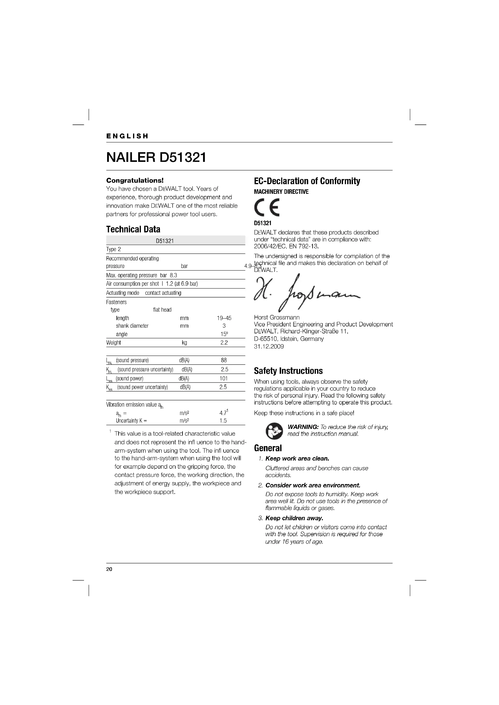
Technical Data
| D51321 | ||
| Type 2 | ||
| Recommended operating pressure | bar | 4 |
| Max. operating pressure bar 8.3 | ||
| Air consumption per shot | 1.2 (at 6.9 bar) | ||
| Actuating mode contact actuating | ||
| Fasteners | ||
| type | flat head | |
| length | mm | 19-45 |
| shank diameter | mm | 3 |
| angle | 15° | |
| Weight | kg | 2.2 |
| LFA (sound pressure) | dB(A) | 88 |
| KVA (sound pressure uncertainty) | dB(A) | 2.5 |
| LVA (sound power) | dB(A) | 101 |
| KVA (sound power uncertainty) | dB(A) | 2.5 |
| Vibration emission value ah | ||
| ah= | m/s² | 4.7¹ |
| Uncertainty K = | m/s² | 1.5 |
This value is a tool-related characteristic value and does not represent the influence to the hand-arm-system when using the tool. The influence to the hand-arm-system when using the tool will for example depend on the gripping force, the contact pressure force, the working direction, the adjustment of energy supply, the workpiece and the workpiece support.
EC-Declaration of Conformity
MACHINERY DIRECTIVE

D51321
DEWALT declares that these products described under "technical data" are in compliance with: 2006/42/EC, EN 792-13.
The undersigned is responsible for compilation of the technical file and makes this declaration on behalf of DEWALT.

Horst Grossmann
Vice President Engineering and Product Development
DEWALT, Richard-Klinger-Straße 11, D-65510, Idstein, Germany
31.12.2009
Safety Instructions
When using tools, always observe the safety regulations applicable in your country to reduce the risk of personal injury. Read the following safety instructions before attempting to operate this product.
Keep these instructions in a safe place!

WARNING: To reduce the risk of injury, read the instruction manual.
General
- Keep work area clean.
Cluttered areas and benches can cause accidents.
- Consider work area environment.
Do not expose tools to humidity. Keep work area well lit. Do not use tools in the presence of flammable liquids or gases.
- Keep children away.
Do not let children or visitors come into contact with the tool. Supervision is required for those under 16 years of age.
4. Store idle tools.
When not in use, tools must be stored in a dry place and locked up securely, out of reach of children.
5. Dress properly.
Do not wear loose clothing or jewellery. They can be caught in moving parts. Preferably wear rubber gloves and non-slip safety footwear. Wear protective hair covering to keep long hair out of the way.
6. Do not overreach.
Keep proper footing and balance at all times.
7. Stay alert.
Watch what you are doing. Use common sense. Do not operate the tool when you are tired.
8. Use appropriate tool.
The intended use is described in this instruction manual. Do not force small tools or attachments to do the job of a heavy-duty tool. The tool will do the job better and safer at the rate for which it was intended.
WARNING! The use of any accessory or attachment or performance of any operation with this tool, other than those recommended in this instruction manual, may present a risk of personal injury.
9. Maintain tools with care.
Keep the tools in good condition and clean for better and safer performance. Follow the instructions for maintenance and changing accessories. Keep all controls dry, clean and free from oil and grease.
10. Check for damaged parts.
Before using the tool, carefully check it for damage to ensure that it will operate properly and perform its intended function. Check for misalignment and seizure of moving parts, breakage of parts and any other conditions that may affect its operation. Have damaged guards or other defective parts repaired or replaced as instructed.
11. Have your tool repaired by an authorised DEWALT repair agent.
This tool is in accordance with the relevant safety regulations. To avoid danger, tools must only be repaired by qualified technicians.
Additional safety instructions for pneumatic tools
- Use quick-action couplings for connection to the compressed air system. The non-sealable nipple must be fitted to the tool in such a way that no compressed air remains in the tool after disconnection.
Always use clean, dry compressed air. Do not use oxygen or combustible gases as an energy source for this tool. - Only connect this tool to an air supply where the maximum allowable pressure of the tool cannot be exceeded by more than 10% . In case of higher pressures, a pressure reducing valve including a downstream safety valve shall be built into the compressed air supply.
- Only use hoses with a rating exceeding the maximum operating pressure of the tool.
- Before transporting the tool, disconnect it from the compressed air system, especially where ladders are used or where unusual physical posture is adopted while moving.
- Disconnect the tool from the air supply when it is not in use.
Additional safety instructions for fastener driving tools
Always wear safety glasses.
Always wear ear protection.
- Never load fasteners with the trigger activated.
- Only use fasteners of the type specified in the manual.
- Do not use any stands for mounting the tool to a support.
- Do not disassemble or block any parts of the fastener driving tool such as the safety yoke.
- Prior to each operation check that the safety and triggering mechanism is functioning properly and that all nuts and bolts are tight.
- Do not use the equipment as a hammer.
- Never point any operational fastener driving tool at yourself or at any other person. Do not use the tool in applications requiring operation close to the body.
- While working, hold the tool in such a way that no injuries can be caused to the head or to the body in the event of a possible recoil due to a disruption in the energy supply or hard areas within the workpiece.
ENGLISH
- Never actuate the fastener driving tool into free space.
- Consider the conditions in the work area. Fasteners can penetrate thin workpieces or slip off corners and edges of the workpiece, and thus put people at risk.
- Do not drive fasteners close to the edge of the workpiece.
- Do not drive fasteners on top of other fasteners.
In the work area, carry the tool using only one handle, and never with the trigger actuated. - Unload the tool after use and before performing any maintenance.
Markings on Tool
The following pictograms are shown on the tool:

Read instruction manual before use.

Wear ear protection.

Wear eye protection.

Pneumatic tool with safety yoke.

Do not use the tool on a ladder.

Compatible fastener angles.

Maximum number of fasteners in magazine.

Fastener length.

Fastener diameter.

Max. operating pressure.

Tool weight.
DATE CODE POSITION (FIG. A)
The Date Code (20), which also includes the year of manufacture, is printed into the housing.
Example:
2010 XX XX
Year of Manufacture
Package contents
The package contains:
1 Nailer
1 Sequential action trigger
1 Safety glasses
1 Hex key 3 mm
1 Hex key 4 mm
1 Instruction manual
- Check for damage to the tool, parts or accessories which may have occurred during transport.
Take the time to thoroughly read and understand this manual prior to operation.
Description (fi g. A)
1 Trigger
2 Lock-off switch
3 Depth adjustment wheel
4 Contact trip
5 Magazine
6 Magazine latch
7 Nail guide door
8 Shingle gauge
9 Air fitting
INTENDED USE
Your nailer D51321 has been designed for driving fasteners into wooden workpieces.
DO NOT use under wet conditions or in presence of flammable liquids or gases.
This pneumatic nailer is a professional power tool.
DO NOT let children come into contact with the tool. Supervision is required when inexperienced operators use this tool.
ASSEMBLY AND ADJUSTMENT
Trigger selection (fi g. B)
These tools are assembled with a bump action trigger. A sequential action trigger is also included with the original packaging. For defi nitions of "bump action" and "sequential action", see below.
- The grey trigger with a single fastener printed on the side is the sequential action trigger. Installation of this kit causes the tool to function in sequential action mode.
- The black trigger with three fasteners printed on the side is the bump action trigger. Installation of this kit causes the tool to function in bump action mode.
Removing the trigger
- Disconnect the airline from the tool.
- Remove all fasteners from the magazine.
- Remove the rubber grommet (10) from the end of the dowel pin (11).
- Remove the dowel pin.
- Remove the trigger assembly (12).
Fitting the trigger
- Insert the trigger assembly into the trigger cavity, ensuring that the trigger spring (13) is properly seated.
- Insert the dowel pin (11) through the tool frame, contact trip guide and trigger assembly.
- Push the rubber grommet (10) onto the end of the dowel pin.
Air fi tting (fi g. A)
These tools have a standard 1/4" pipe thread for the air fitting (9).
- Wrap the male end of the fitting with Teflon tape to prevent air leaks.
- Screw the fitting into the end cap and tighten firmly.
Loading the tool (fi g. A, C, D)
- Push the magazine latch (6) to open the magazine door (14).
- Open and move the nail guide door (7) out of the way.
- Adjust the platform (15) to accommodate the required nail length by turning the lever (16) to the required position.
- Place the nail coil (17) over the spindle (18).
- Uncoil enough nails to feed into the nosepiece of the tool.
- Feed the nails into the nosepiece in such a way that the second nail locates between the rails of the feed pawl (19).
- Close the nail guide door (7).
- Close the magazine door (14) completely by engaging the magazine latch (6) and locking the magazine closed.
Unloading the tool (fi g. A, C, D)
- Push the magazine latch (6) to open the magazine door (14).
- Open and move the nail guide door (7) out of the way.
- Remove the nail coil (17) from the spindle (18).

WARNING: Always disconnect the tool from the air supply before loading or unloading fasteners.
Adjusting the driving depth (fi g. E)
The driving depth can be adjusted to the type of fastener used.

WARNING: To reduce risk of serious injury from accidental actuation when attempting to adjust depth, ALWAYS:
- Lock OFF trigger.
- Disconnect air supply.
- Avoid contact with trigger during adjustments.
To reduce the depth, turn the depth adjustment wheel (3) to the right.
To increase the depth, turn the wheel (3) to the left.
Trigger lock (f g. A)
This tool is equipped with a trigger lock-off switch which prevents the tool from firing a fastener.
To engage the trigger lock, push the switch (2) to the right.
To release the trigger lock, push the switch to the center.
Adjusting the shingle gauge (fi g. F)
- Loosen the screw (22) using the hex key supplied.
- Move the gauge (8) up or down to attain the desired position.
OPERATION
Instructions for Use

WARNING: Always observe the safety instructions and applicable regulations.
Proper Hand Position (fi g. G)

WARNING: To reduce the risk of serious personal injury, ALWAYS use proper hand position as shown.

WARNING: To reduce the risk of serious personal injury, ALWAYS hold securely in anticipation of a sudden reaction.
Proper hand position requires one hand on the main handle (21).
Preparing the tool (fig. A)
- Drain all condensation from the air compressor tanks and hoses.
- Lubricate the tool. See "Maintenance".
- Remove all fasteners from the magazine.
- Check if the contact trip (4) can move freely.

WARNING: Do not use the tool if the contact trip cannot move freely.
- Check that the pressure of the air supply is below the maximum recommended operating pressure.
- Connect the air hose to the fitting on the tool.
- Check for audible leaks around valves and gaskets.
- Set the air pressure to the minimum required operating pressure for your application.

WARNING: Never use a tool that leaks or has damaged parts.
Cold weather operation
When operating tools at temperatures below freezing:
- Keep the tool as warm as possible before use.
- Disconnect the airline from the tool.
- Put 10 to 15 drops of DEWALT pneumatic tool oil (or winter-weight pneumatic oil containing ethylene glycol) into the air inlet.
- Set the air pressure to a maximum of 5.5 bar.
- Connect the air hose to the fitting on the tool.
- Load fasteners into the magazine as described above.
- Actuate the tool 5 or 6 times into scrap lumber to lubricate the o-rings.
- Increase the air pressure to the normal operating level.
- Use the tool in the normal manner.
Hot weather operation
The tool should operate normally. Avoid the heat of direct sunlight to avoid damage to the bumpers, o-rings, and other rubber parts.
Actuating the tool (fi g. A)
The tool can be operated using one of two modes. The trigger installed on the tool determines the mode of actuation.
Sequential action mode
The sequential action mode is used for intermittent fastening when very careful and accurate placement is desired.
- Fit the grey trigger as described above.
- Release the trigger lock (2).
- Push the contact trip (4) against the work surface.
- Pull the trigger (1) to actuate the tool. Each trigger pull with the contact trip pushed against the work surface will drive one fastener.
Bump action mode
The bump action mode is used for rapid fastening on fl at, stationary surfaces.
- Fit the black trigger as described above.
- Release the trigger lock (2).
To drive a single fastener: Operate the tool as described for sequential action. - To drive several fasteners: Pull the trigger (1) first, and then push the contact trip (4) repeatedly against the work surface.

WARNING: Do not keep the trigger depressed when the tool is not in use. Keep the trigger lock engaged to prevent
Keep the trigger lock engaged to prevent accidental actuation when the tool is not in use.
Clearing a jammed fastener (fig. A, C, D)
If a fastener becomes jammed in the nosepiece, follow these instructions to remove the fastener:
- Disconnect the airline from the tool.
- Engage the trigger lock (2).
- Open and move the nail guide door (7) out of the way.
- Remove the bent fastener, using pliers if necessary.
- If the driving blade is in the down position, push the driving blade upward using a screwdriver.
- Correct any deformation that may have occurred to the nail coil.
- Feed the fasteners into the nose piece as described under "Loading the tool".
- Close the nail guide door.

WARNING: If fasteners become jammed in the nosepiece frequently, have the tool serviced by an authorised DEWALT service centre.
Optional accessories
Consult your dealer for further information on the appropriate accessories.
MAINTENANCE
Your DEWALT tool has been designed to operate over a long period of time with a minimum of maintenance. Continuous satisfactory operation depends on proper tool care and regular cleaning.
The following maintenance operations must be performed every day.

Cleaning
- Clean the magazine and the nosepiece using compressed air.
- Clean the front end of the contact trip using fuel oil or diesel fuel.
Draining
- Drain all condensation from the air compressor tanks and hoses.

Lubrication
- Insert 5-7 drops pneumatic tool oil into the air fitting on the end cap of the tool.
Checking
- Ensure that all fasteners on the tool are tight and undamaged.
- Tighten loose fasteners using the appropriate tool.
Protecting the environment

Separate collection. This product must not be disposed of with normal household waste.

Should you find one day that your DEWALT product needs replacement, or if it is of no further use to you, do not dispose of it with household waste. Make this product available for separate collection.

Separate collection of used products and packaging allows materials to be recycled and used again. Re-use of recycled materials helps prevent environmental pollution and reduces the demand for raw materials.
Local regulations may provide for separate collection of electrical products from the household, at municipal waste sites or by the retailer when you purchase a new product.
DEWALT provides a facility for the collection and recycling of DEWALT products once they have reached the end of their working life. To take advantage of this service please return your product to any authorised repair agent who will collect them on our behalf.
You can check the location of your nearest authorised repair agent by contacting your local DEWALT offi ce at the address indicated in this manual. Alternatively, a list of authorised DEWALT repair agents and full details of our after-sales service and contacts are available on the Internet at: www.2helpU.com.
GUARANTEE
DEWALT is confident of the quality of its products and offers an outstanding guarantee for professional users of the product. This guarantee statement is in addition to and in no way prejudices your contractual rights as a professional user or your statutory rights as a private non-professional user. The guarantee is valid within the territories of the Member States of the European Union and the European Free Trade Area.
30 DAY NO RISK SATISFACTION GUARANTEE
If you are not completely satisfied with the performance of your DEWALT tool, simply return it within 30 days, complete with all original components, as purchased, to the point of purchase, for a full refund or exchange. The product must have been subject to fair wear and tear and proof of purchase must be produced.
- ONE YEAR FREE SERVICE CONTRACT
If you need maintenance or service for your DEWALT tool, in the 12 months following purchase, you are entitled to one service free of charge. It will be undertaken free of charge at an authorised DEWALT repair agent. Proof of purchase must be produced. Includes labour. Excludes accessories and spare parts unless failed under warranty.
- ONE YEAR FULL WARRANTY
If your DEWALT product becomes defective due to faulty materials or workmanship within 12 months from the date of purchase, DEWALT guarantees to replace all defective parts free of charge or - at our discretion - replace the unit free of charge provided that:
The product has not been misused;
The product has been subject to fair wear and tear;
- Repairs have not been attempted by unauthorised persons;
Proof of purchase is produced;
The product is returned complete with all original components.
If you wish to make a claim, contact your seller or check the location of your nearest authorised DEWALT repair agent in the DEWALT catalogue or contact your DEWALT office at the address indicated in this manual. A list of authorised DEWALT repair agents and full details of our after-sales service is available on the Internet at: www.2helpU.com.
CLAVADORAD51321
Enhorabuena!
L'emballage content:
Trekkervergrendeling (afb. A)
Vice President Engineering and Product Development
DEWALT, Richard-Klinger-Strasse 11,
D-65510, Idstein, Germany
31.12.2009
Turvallisuusohjeet
CIVITABANCASI D51321
Tebrikler!
Meyotn pieon aeitoupyiac.

Bapoc
OESH KΩΔIKOY HMEPOMHNIAZ (EIK. [FIG.] A)
O kwdioc nepoynviac (20), o otioic Tepiaaabeve ETIOG TO ETOC KATAOKEURG, EVAI TUTWUEVOC ETTAW OTo TEPiBAnu.
NapadEiyua:
2010 XX XX
EtoKataoKeuHS
EeYxos Tou nepieoxouevou Tns oukeuaias


- EC-Declaration of Conformity
- MACHINERY DIRECTIVE
- D51321
- Safety Instructions
- General
- Store idle tools.
- Dress properly.
- Do not overreach.
- Stay alert.
- Use appropriate tool.
- Maintain tools with care.
- Check for damaged parts.
- Have your tool repaired by an authorised DEWALT repair agent.
- Additional safety instructions for pneumatic tools
- Additional safety instructions for fastener driving tools
- ENGLISH
- Markings on Tool
- DATE CODE POSITION (FIG. A)
- Package contents
- Description (fi g. A)
- INTENDED USE
- ASSEMBLY AND ADJUSTMENT
- Trigger selection (fi g. B)
- Removing the trigger
- Fitting the trigger
- Air fi tting (fi g. A)
- Loading the tool (fi g. A, C, D)
- Unloading the tool (fi g. A, C, D)
- Adjusting the driving depth (fi g. E)
- Trigger lock (f g. A)
- Adjusting the shingle gauge (fi g. F)
- OPERATION
- Instructions for Use
- Proper Hand Position (fi g. G)
- Preparing the tool (fig. A)
- Cold weather operation
- Hot weather operation
- Actuating the tool (fi g. A)
- Sequential action mode
- Bump action mode
- Clearing a jammed fastener (fig. A, C, D)
- Optional accessories
- MAINTENANCE
- The following maintenance operations must be performed every day.
- Cleaning
- Draining
- Lubrication
- Checking
- Protecting the environment
- GUARANTEE
- DAY NO RISK SATISFACTION GUARANTEE
- - ONE YEAR FREE SERVICE CONTRACT
- - ONE YEAR FULL WARRANTY
- CLAVADORAD51321
- Enhorabuena!
- Trekkervergrendeling (afb. A)
- Turvallisuusohjeet
- CIVITABANCASI D51321
- Tebrikler!
- OESH KΩΔIKOY HMEPOMHNIAZ (EIK. [FIG.] A)
- EeYxos Tou nepieoxouevou Tns oukeuaias
Brand : DEWALT
Model : D51321
Category : Stapler