
USE 8 - Screwdriver METABO - Free user manual and instructions
Find the device manual for free USE 8 METABO in PDF.
| Brand | Metabo |
| Model | USE 8 |
| Product type | Corded electric screwdriver |
| Intended use | Screwing and unscrewing screws, tightening and loosening nuts |
| Input power (P1) | Indicated on rating plate (not specified in manual) |
| Output power (P2) | Indicated on rating plate |
| No-load speed (n0) | Indicated on rating plate |
| Rated speed under load (n1) | Indicated on rating plate |
| Adjustable torque (T1-10) | 10 positions, 1 to 10 |
| Maximum torque (T_max) | Max. position (clutch disengaged) |
| Tool holder (H) | Quick-release chuck |
| Weight (m) | Indicated on rating plate |
| Power supply | Alternating current, mains voltage and frequency per rating plate |
| Protection class | II (double insulation) |
| Sound pressure level (L_pA) | Indicated (may exceed 80 dB(A)) |
| Sound power level (L_WA) | Indicated |
| Vibration emission value (a_h) | Screwdriving without impact, according to EN 62841 |
| Depth stop | Yes, with adjustable stop sleeve (0.25 mm per click) |
| Auxiliary handle | Supplied (USE 8), adjustable mounting |
| Direction of rotation | Switch R (right) / L (left) |
| Continuous operation | Possible with lock-on button |
| Maintenance | Regular cleaning, vacuum deposits from ventilation slots |
| Compatible accessories | Stop sleeves, bit holder, adapter, bits, socket wrenches (see manual) |
| Repairs | Reserved for specialists; specific Metabo power cord |
Frequently Asked Questions - USE 8 METABO
User questions about USE 8 METABO
0 question about this device. Answer the ones you know or ask your own.
Ask a new question about this device
Download the instructions for your Screwdriver in PDF format for free! Find your manual USE 8 - METABO and take your electronic device back in hand. On this page are published all the documents necessary for the use of your device. USE 8 by METABO.
USER MANUAL USE 8 METABO
natural_image
Two Metabo electric drillers with black and silver casing, mounted on a stand (no visible text or symbols)
USE 8

1

natural_image
Mechanical assembly diagram showing a screwdriver inserted into a housing with a directional arrow indicating motion (no text or symbols present)789
 | USE 8 DWSE 6.3*1) Serial Number: 20002.. *1) Serial Number: 20001.. | ||
| P_1 | W 550 | 550 | |
| P_2 | W 290 | 290 | |
| n_0 | min ^-1 (rpm) | 0-900 0-2100 | |
| n_1 | min ^-1 (rpm) | 580 1350 | |
| T_1-10 | Nm 3-18 | 3-18 | |
| T_max. | Nm 40 - | ||
| H mm (in) | 6,35 (1/4“) | 6,35 (1/4“) | |
| m kg (lbs) | 2,0 (4.4) | 2,0 (4.4) | |
| a_h/K_h | m/s ^2 | 2,5 / 1,5 | 2,5 / 1,5 |
| L_pA/K_pA | dB(A) | 82 / 3 | 81 / 3 |
| L_WA/K_WA | dB(A) | 93 / 3 | 92 / 3 |

*2) 2014/30/EU, 2006/42/EC, 2011/65/EU
*3) EN 62841:2015, EN 62841-2-2:2014, EN 50581:2012
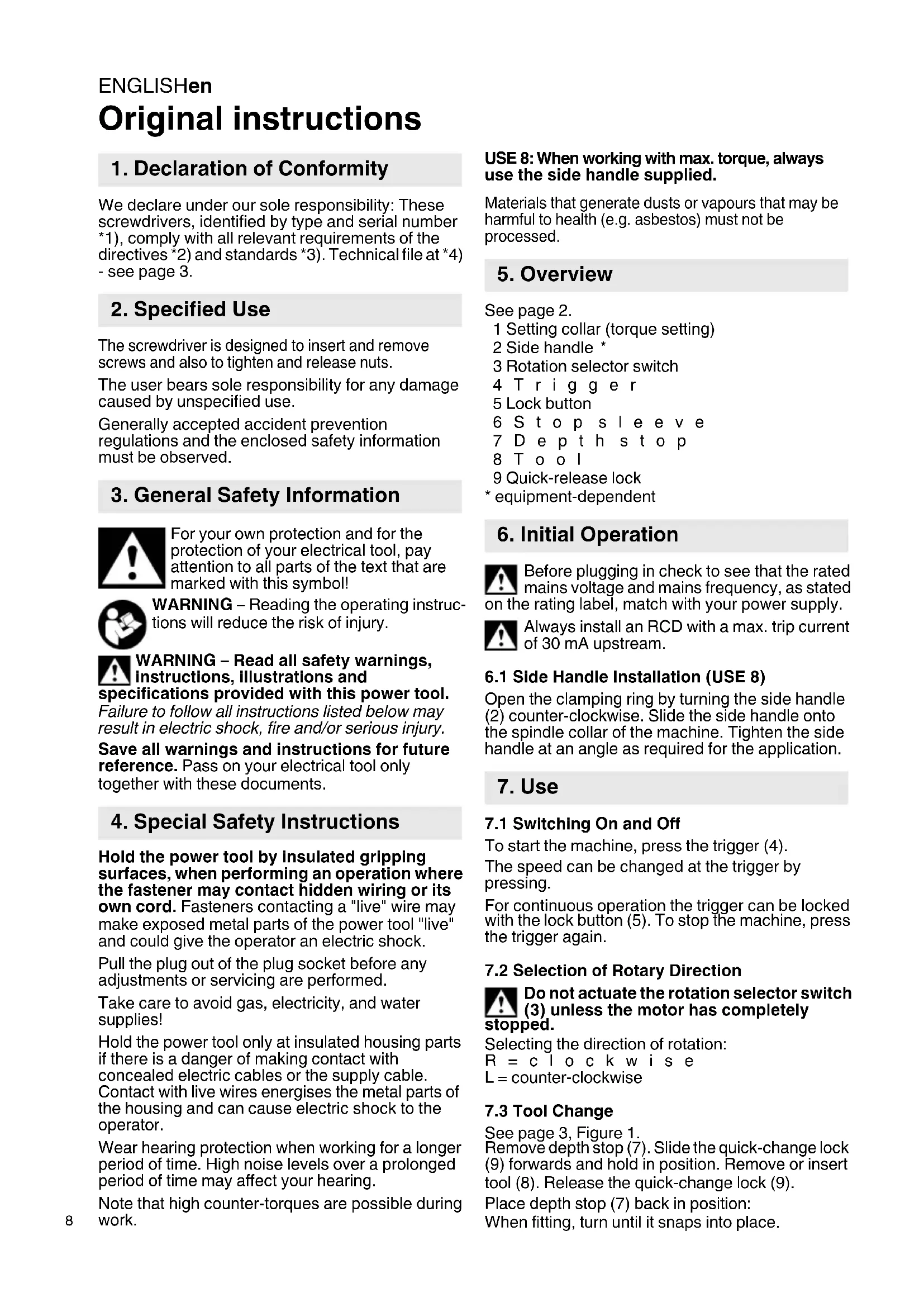
Original instructions
1. Declaration of Conformity
We declare under our sole responsibility: These screwdrivers, identified by type and serial number *1), comply with all relevant requirements of the directives *2) and standards *3). Technical file at *4) - see page 3.
2. Specified Use
The screwdriver is designed to insert and remove screws and also to tighten and release nuts.
The user bears sole responsibility for any damage caused by unspecified use.
Generally accepted accident prevention regulations and the enclosed safety information must be observed.
3. General Safety Information

For your own protection and for the protection of your electrical tool, pay attention to all parts of the text that are marked with this symbol!

WARNING – Reading the operating instructions will reduce the risk of injury.

WARNING – Read all safety warnings, instructions, illustrations and cifications provided with this power tool.
Failure to follow all instructions listed below may result in electric shock, fire and/or serious injury.
Save all warnings and instructions for future reference. Pass on your electrical tool only together with these documents.
4. Special Safety Instructions
Hold the power tool by insulated gripping surfaces, when performing an operation where the fastener may contact hidden wiring or its own cord. Fasteners contacting a "live" wire may make exposed metal parts of the power tool "live" and could give the operator an electric shock.
Pull the plug out of the plug socket before any adjustments or servicing are performed.
Take care to avoid gas, electricity, and water supplies!
Hold the power tool only at insulated housing parts if there is a danger of making contact with concealed electric cables or the supply cable.
Contact with live wires energises the metal parts of the housing and can cause electric shock to the operator.
Wear hearing protection when working for a longer period of time. High noise levels over a prolonged period of time may affect your hearing.
Note that high counter-torques are possible during work.
USE 8: When working with max. torque, always use the side handle supplied.
Materials that generate dusts or vapours that may be harmful to health (e.g. asbestos) must not be processed.
5. Overview
See page 2.
1 Setting collar (torque setting)
2 Side handle *
3 Rotation selector switch
4 Trigger
5 Lock button
6 S t o p s l e e v e
7 Depth stop
8 Tool
9 Quick-release lock
* equipment-dependent
6. Initial Operation

Before plugging in check to see that the rated mains voltage and mains frequency, as stated e rating label, match with your power supply.

Always install an RCD with a max. trip current of 30 mA upstream.
6.1 Side Handle Installation (USE 8)
Open the clamping ring by turning the side handle (2) counter-clockwise. Slide the side handle onto the spindle collar of the machine. Tighten the side handle at an angle as required for the application.
7. Use
7.1 Switching On and Off
To start the machine, press the trigger (4).
The speed can be changed at the trigger by pressing.
For continuous operation the trigger can be locked with the lock button (5). To stop the machine, press the trigger again.
7.2 Selection of Rotary Direction

Do not actuate the rotation selector switch (3) unless the motor has completely ped.
Selecting the direction of rotation:
R = c l o c k w i s e
L = counter-clockwise
7.3 Tool Change
See page 3, Figure 1.
Remove depth stop (7). Slide the quick-change lock (9) forwards and hold in position. Remove or insert tool (8). Release the quick-change lock (9).
Place depth stop (7) back in position:
When fitting, turn until it snaps into place.
7.4 Working with Depth Stop Set torque setting 10 at setting collar (1).
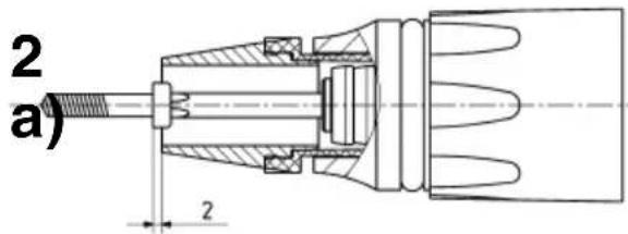
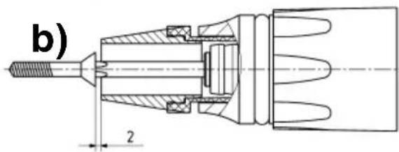
To preset screw insertion depth, one of the screws to be inserted is fitted on the tool. Adjust stop sleeve (6) by turning as follows (see page 3, Figure 2):
a) Screws whose heads are to sit on the material (socket-head screws, oval head screws, hex screws):
The surface area of the screw head is 2 mm outside the stop sleeve.
b) Countersunk screws:
The surface of the countersunk screw head is 2 mm outside the stop sleeve.
Insert a screw as a test. Correct the insertion depth if necessary:
When the stop sleeve (6) is inserted, the insertion depth changes by 0.25 mm per notch. If screw insertion has to be deeper: insert stop sleeve. If the screw has been too deeply inserted: unscrew stop sleeve.
Removal of the depth stop (7) does not alter the set screw insertion depth. After refitting, work can continue at the same insertion depth.

When screwing in cross-head screws, press the machine with the screwdriver bit firmly fast the screw until the screw is fully inserted; rwise the bit could slip out of the cross recess damage the material.
If the machine is not held exactly vertical in relation to the tool, the depth stop counterbalances this (to a certain extent).
7.5 Working with torque setting Remove depth stop (7).
Make torque setting at setting collar (1). Torque setting:
Position 1-10,
Once the pre-selected torque has been achieved, the screwdriver clutch makes a rattling sound and the screwing procedure can be stopped.

USE 8: On the setting collar (1) for torque setting, position max. and position 1 are arranged beside other. The setting collar cannot be turned directly Position max. to Position 1 (or from 1 to max.)! Turn opposing direction (i.e. passing through the others).
Position max., (only USE 8):
(turn the setting collar until it engages.) The screwdriver clutch is switched off. The maximum possible torque is available.

USE 8: When working with max. torque, always use the side handle supplied.

Note that high counter-torques are possible during work.
8. Tips and Tricks
Screwing in wood: Once the pre-selected torque has been achieved, the screwdriver clutch makes a rattling sound and the screws can slowly be inserted to the desired insertion depth.
When using short screwdriver bits (25 mm): use a bit holder. (see Accessories section).
Screw wooden boards with wing screws (Tek) onto steel: Work at low rotational speeds when drilling through the wooden board. When you reach the steel, work at maximum rotational speed.
9. Troubleshooting
If it is hard to remove the bit holder from the toolholder: pull out with pliers.
If the trigger (4) can not be depressed, check to see that the direction of rotation selector switch (3) is fully set to the R or L position.
10. Maintenance
Clean the machine regularly. This includes vacuum cleaning the ventilation louvres on the motor.
11. Accessories
Use only genuine Metabo accessories.
See page 4.
Use only accessories which fulfil the requirements and specifications listed in these operating instructions.
A Depth stop sleeves
B Bit holder
C Connector
D Screwdriver bits
E Wrench sockets (commercially available)
F Hexagon wrench socket
For complete range of accessories, see www.metabo.com or the main catalogue.
12. Repairs
Repairs to electrical tools must be carried out by qualified electricians ONLY!
A defective mains cable must only be replaced with a special, original mains cable from metabo, which is available only from the Metabo service.
If you have Metabo electrical tools that require repairs, please contact your Metabo service centre. For addresses see www.metabo.com.
You can download spare parts lists from www.metabo.com.
13. Environmental Protection
Observe national regulations on environmentally compatible disposal and on the recycling of disused machines, packaging and accessories.

Only for EU countries: Never dispose of power tools in your household waste! In accordance with European Directive 2012/
19/EU on waste electrical and electronic equipment and its implementation in national law, used electrical tools must be collected separately and handed in for environmentally compatible recycling.
ENGLISHen
14. Technical Specifications
Explanatory notes on the information on page 2.
Changes due to technological progress reserved.
P_1 =Rated power consumption
P_2 =Power output
n_0= No load speed
n_1 = On load speed
T_1-10 = Torque (adjustable)
T_max. = max.torque
H = Machine toolholder
m = W e i g h t
Measured values determined in conformity with EN 62841.
□ Machine in protection class II
\~ AC Power
The technical specifications quoted are subject to tolerances (in compliance with the relevant valid standards).
Emission values
These values make it possible to assess the emissions from the power tool and to compare different power tools. Depending on the operating conditions, the condition of the power tool or the accessories, the actual load may be higher or lower. For assessment purposes, please allow for breaks and periods when the load is lower. Based on the adjusted estimates, arrange protective measures for the user e.g. organisational measures.
Vibration total value (vector sum of three directions) determined in accordance with EN 62841:
a_h =Vibration emission value (Screwdriving without impact)
K_h = Unsafe (vibration)
Typical A-effective perceived sound levels:
L_pA = Sound-pressure level
L_WA = Acoustic power level
K_pA, K_WA = Uncertainty
During operation the noise level can exceed 80 dB(A).

Wear ear protectors!
Notice originale
Voir page 3, figure 1
K_n = Incertitude (oscillation)
3 Rotationsomkopplare


- Original instructions
- Declaration of Conformity
- Specified Use
- General Safety Information
- Special Safety Instructions
- Overview
- Initial Operation
- Side Handle Installation (USE 8)
- Use
- Switching On and Off
- Selection of Rotary Direction
- Tool Change
- Working with Depth Stop Set torque setting 10 at setting collar (1).
- Working with torque setting Remove depth stop (7).
- Tips and Tricks
- Troubleshooting
- Maintenance
- Accessories
- Repairs
- Environmental Protection
- ENGLISHen
- Technical Specifications
- Emission values
- Notice originale
Brand : METABO
Model : USE 8
Category : Screwdriver