
Fatmax FMHT77447 - Laser pointer STANLEY - Free user manual and instructions
Find the device manual for free Fatmax FMHT77447 STANLEY in PDF.
| Product Type | Rotating laser level with self-leveling |
| Brand | Stanley |
| Model | Fatmax FMHT77447 |
| Horizontal accuracy | ±1.5 mm at 30 m |
| Vertical accuracy | ±3.0 mm at 30 m |
| Compensation range | 5° |
| Rotation speed | 0, 150, 300, 600 rpm |
| Range with detector | Up to 600 m |
| Laser class | Class 2 (IEC 60825-1:2014) |
| Wavelength | 630 - 680 nm (red) |
| Power supply | Rechargeable Li-Ion battery |
| Battery life | ≥ 40 hours |
| Charging time | ≤ 7 hours |
| Protection rating | IP66 |
| Operating temperature range | -10°C to +40°C |
| Self-leveling | Yes, compensation up to 5° |
| Operating modes | Manual, slope, point, scan |
| Remote control | Included, range 15 m |
| Detector | Included, accuracy ≤1 mm (high) |
| Maintenance | Clean with a damp cloth, do not use solvent |
| Safety | Do not look directly into the beam, class 2 |
| Warranty | Consult Stanley after-sales service |
Frequently Asked Questions - Fatmax FMHT77447 STANLEY
User questions about Fatmax FMHT77447 STANLEY
0 question about this device. Answer the ones you know or ask your own.
Ask a new question about this device
Download the instructions for your Laser pointer in PDF format for free! Find your manual Fatmax FMHT77447 - STANLEY and take your electronic device back in hand. On this page are published all the documents necessary for the use of your device. Fatmax FMHT77447 by STANLEY.
USER MANUAL Fatmax FMHT77447 STANLEY
Please read these instructions before operating the product.


RL600
RL600L
RL700L
RL 750L-G
(1)


1
②
3
(4)
Contents
- User Safety
- Keypad and LEDs
- Battery Safety
- Batteries and Power
Using the Accessories - Turning the Laser On/Off
Performing Accuracy Check and Calibration - Operating the Laser
Using the Remote Control
Using the Detector - Maintenance and Care
- Specifications
User Safety
The definitions below describe the level of severity for each signal word. Please read the manual and pay attention to these symbols.

DANGER: Indicates an imminently hazardous situation which, if not avoided, will result in death or serious injury.

WARNING: Indicates a potentially hazardous situation which, if not avoided, could result in death or serious injury.

CAUTION: Indicates a potentially hazardous situation which, if not avoided, may result in minor or moderate injury.
NOTICE: Indicates a practice not related to personal injury which, if not avoided, may result in property damage.
If you have any questions or comments about this or any Stanley tool, go to http://www.2helpU.com.

WARNING:
Read and understand all instructions. Failure to follow the warnings and instructions in this manual may result in serious personal injury.
SAVE THESE INSTRUCTIONS

WARNING:
Carefully read the Safety Instructions and Product Manual before using this product. The person responsible for the instrument must ensure that all users understand and adhere to these instructions.

CAUTION:
While the laser tool is in operation, be careful not to expose your eyes to the emitting laser beam. Exposure to a laser beam for an extended time may be hazardous to your eyes.

CAUTION:
Glasses are supplied in some of the laser tool kits.
These are NOT certified safety glasses. These glasses are ONLY used to enhance the visibility of the beam in brighter environments or at greater distances from laser source.
SAVE THESE INSTRUCTIONS

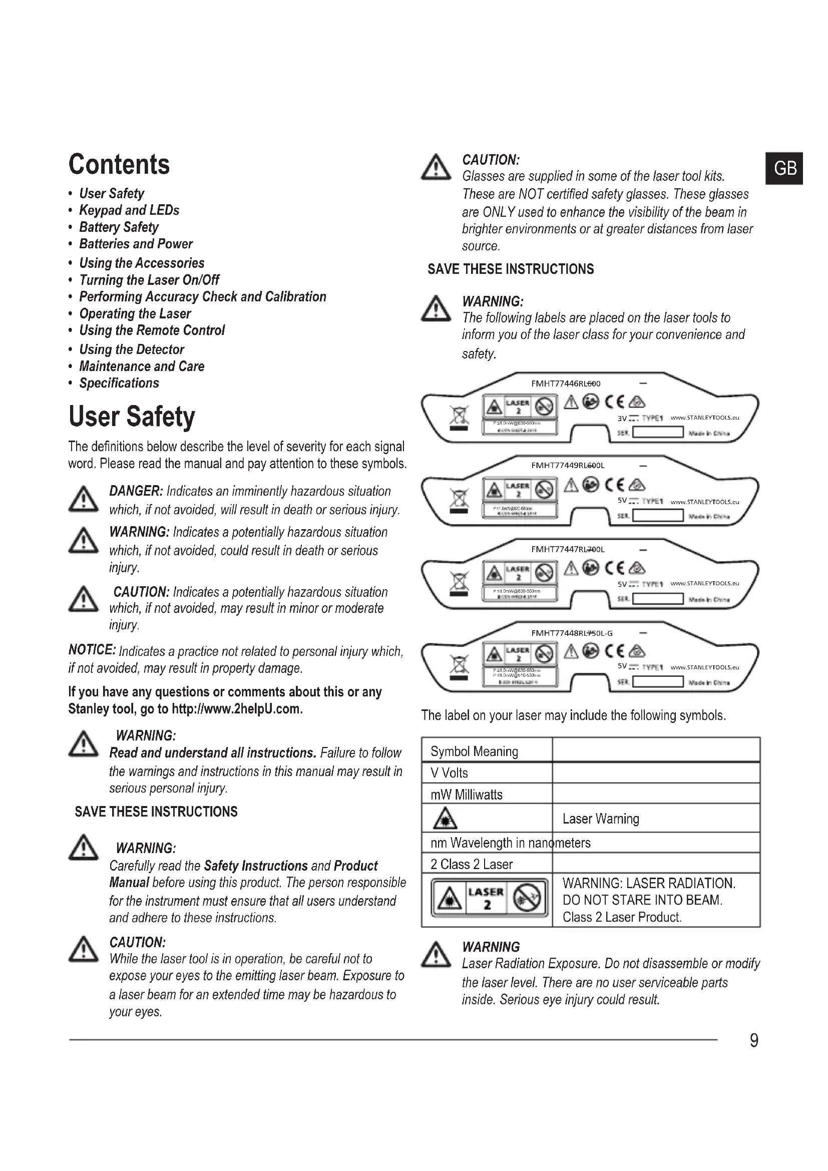
WARNING:
The following labels are placed on the laser tools to inform you of the laser class for your convenience and safety.
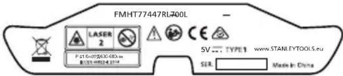
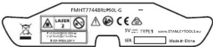
The label on your laser may include the following symbols.
| Symbol Meaning | |
| V Volts | |
| mW Milliwatts | |
| Laser Warning | |
| nm Wavelength in nanometers | |
| 2 Class 2 Laser | |
| WARNING: LASER RADIATION. DO NOT STARE INTO BEAM. Class 2 Laser Product. | |

WARNING
Laser Radiation Exposure. Do not disassemble or modify the laser level. There are no user serviceable parts inside. Serious eye injury could result.
GB
- Do not operate the laser in explosive atmospheres, such as in the presence of flammable liquids, gases, or dust. This tool may create sparks which may ignite the dust or fumes.
- Store an idle laser out of reach of children and other untrained persons. Lasers are dangerous in the hands of untrained users.
- Tool service MUST be performed by qualified repair personnel. Service or maintenance performed by unqualified personnel may result in injury. To locate your nearest Stanley service center go to http://www.2helpU.com.
- Do not use optical tools such as a telescope or transit to view the laser beam. Serious eye injury could result.
- Do not place the laser in a position which may cause anyone to intentionally or unintentionally stare into the laser beam. Serious eye injury could result.
- Do not position the laser near a reflective surface which may reflect the laser beam toward anyone's eyes. Serious eye injury could result.
- Store an idle laser out of reach of children and other untrained persons. Lasers are dangerous in the hands of untrained users.
- Turn the laser off when it is not in use. Leaving the laser on increases the risk of staring into the laser beam.
- Do not modify the laser in any way. Modifying the tool may result in hazardous laser radiation exposure.
- Do not operate the laser around children or allow children to operate the laser. Serious eye injury may result.
- Do not remove or deface warning labels. If labels are removed, the user or others may inadvertently expose themselves to radiation.
- Position the laser securely on a level surface. If the laser falls, damage to the laser or serious injury could result.
Personal Safety
- Stay alert, watch what you are doing, and use common sense when operating the laser. Do not use the laser when you are tired or under the influence of drugs, alcohol, or medication. A moment of inattention while operating the laser may result in serious personal injury.
- Use personal protective equipment. Always wear eye protection. Depending on the work conditions, wearing protective equipment such as a dust mask, nonskid safety shoes, hard hat, and hearing protection will reduce personal injury.
Tool Use and Care
- Follow instructions in the Maintenance and Care section of this manual. Use of unauthorized parts or failure to follow Maintenance and Care instructions may create a risk of electric shock or injury.
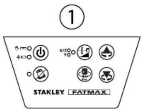
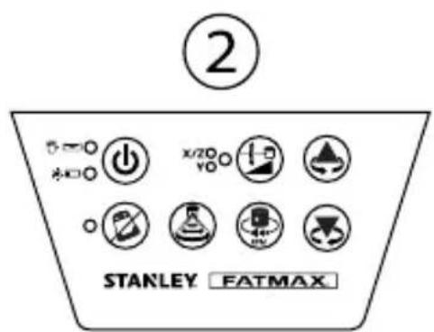
Keypad and LEDs Keypad
To reference keypad and LED display, see Figure (已)1 (RL 600 and RL 600L) or Figure (已)2 (RL 700L and RL 750L-G).

Power ON/OFF Key

Tilt Warning ON/OFF Key

Scan Mode Key
RL 700L and RL 750L-G only.

Manual Slope Mode Key

Rotation Speed Key

Up Arrow Key (counterclockwise)

Down Arrow Key (clockwise)
LEDS
| Power LED | |
| Solid Green • Charging complete. • Auto-Levelling Complete. | |
| Flashing Green • Laser Tool is Auto-Levelling. • In Calibration and/or Default Tilt Warning Set Up. | |
| Flashing Red | • Low Battery. |
| Solid Red RL 600L, RL 700L, & RL 750L-G | • Battery needs recharging, power supply required. • Hot/Cold battery delay or cell failure. Laser can be operated by adapter power. |
Manual LED


Flashing Red - Manual Mode ON (Auto-Levelling OFF).
Power LED & Manual LED
Alternately Flashing Green and Red
- Out of Leveling Compensation Range.
Tilt Warning LED
Solid Red · Tilt Warning ON.
Flashing Red
Out of level.
X/Y Select LED


Solid Green · X Axis Adjust Slope Mode.
Solid Red
- Y Axis Adjust Slope Mode.
Flashing Green · X Axis at Maximum Allowed Slope in Slope Mode.
- X axis adjust Calibration Mode.
Flashing Red
-
Y Axis at Maximum Allowed Slope in Slope Mode.
-
Y axis adjust Calibration Mode.
Battery Safety
The RL 600 is powered by alkaline batteries. The RL 600L, RL 700L, and RL 750L-G are powered by a Li-ion battery.

WARNING:
To reduce the risk of injury, the user must read the product User Manual, the Laser Safety Manual, and the Battery Safety Manual.

WARNING:
The battery and charging/power adapter can be damaged if damp. Always store and charge the tool in a dry and covered place.

Always insert batteries correctly with regard to polarity (+ and -), as marked on the battery and the equipment. Do not mix old and new batteries.
Replace all batteries at the same time with new batteries of the same brand and type.

WARNING:
Batteries can explode, or leak, and can cause injury or fire. To reduce this risk:
- Carefully follow all instructions and warnings on the battery label and package.
- Do not mix battery chemistries.
- Do not dispose of batteries in fire.
- Keep batteries out of reach of children.
- Remove batteries if the device will not be used for several months.
- Do not short battery terminals.
- Do not charge disposable batteries.
- Remove dead batteries immediately and dispose of per local codes.
End of Life
DO NOT dispose of this product with household waste.
ALWAYS dispose of batteries per local code.
PLEASE RECYCLE in line with local provisions for the collection and disposal of electrical and electronic waste under the WEEE Directive.
EC-Declaration of Conformity Radio Equipment Directive

Stanley Fatmax Self-Leveling Rotary Laser FMHT77446, FMHT77449, FMHT77447, FMHT77448
Stanley hereby declares that the Stanley Fatmax Self-Leveling Rotary Laser FMHT77446/FMHT77449/FMHT77447/ FMHT77448 is in compliance with the Directive 2014/53/EU and to all applicable EU directive requirements.
The full text of the EU Declaration of Conformity can be requested at Stanley Tools, Egide Walschaertsstraat 14-16, 2800 Mechelen, Belgium or is available at the following internet address: www.2helpU.com.
Search by the Product and Type Number indicated on the nameplate.

GB
Stanley Tools declares that the CE Mark has been applied to this product in accordance with the CE Marking Directive 93/68/EEC.
This product conforms with IEC/EN60825-1:2014.
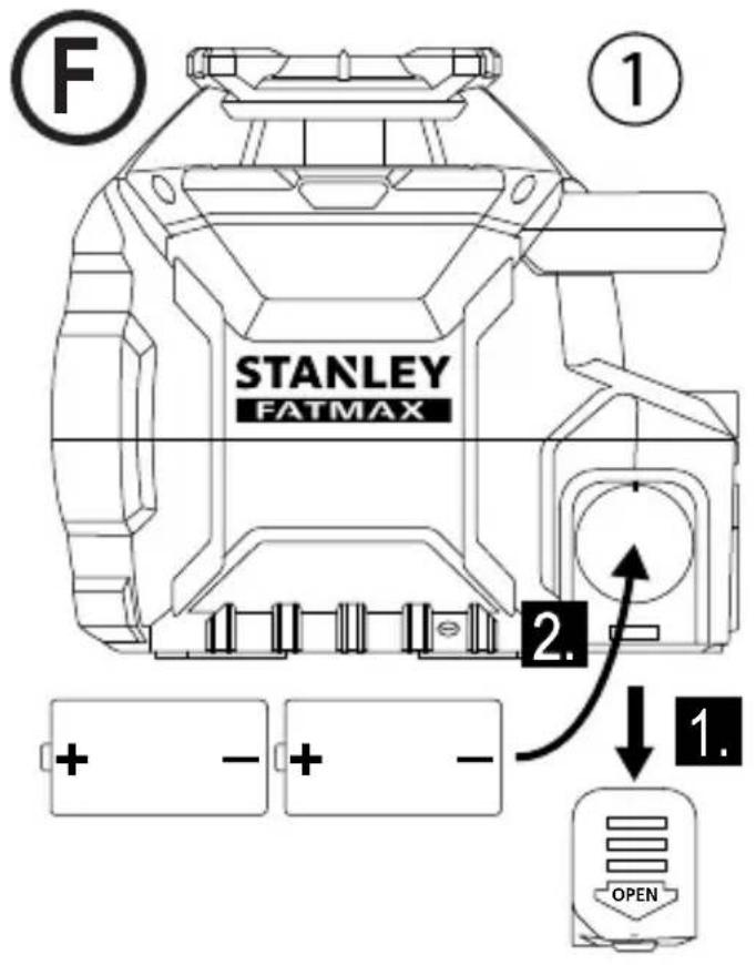
Batteries and Power Battery Installation
Laser Tool Battery Installation
RL600
See Figure E①
- Press battery compartment cover and slide out.
- Install two new D cell batteries. Orient batteries correctly when placing into laser tool.
- Securely close and lock battery compartment cover.
Remote Control Battery Installation RL 600L, RL 700L, and RL 750L-G
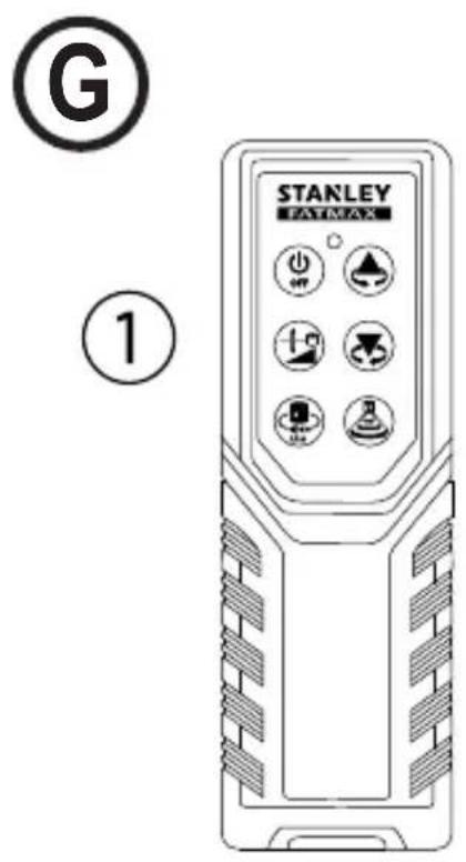
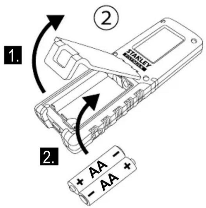
See Figure G②
- Open battery compartment by unlatching cover.
- Install two new AA batteries. Orient batteries correctly when placing into laser tool.
- Securely close and lock battery compartment cover.
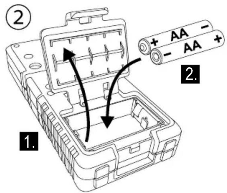
Detector Battery Installation
See Figure C2
- Open battery compartment by lifting open battery cover.
- Install two new AA batteries. Orient batteries correctly when placing into laser tool.
- Securely close and lock battery compartment cover.

WARNING:
Pay close attention to the battery holder's (+) and (-) markings for proper battery insertion. Batteries must be of same type and capacity. Do not use a combination of batteries with different capacities remaining.
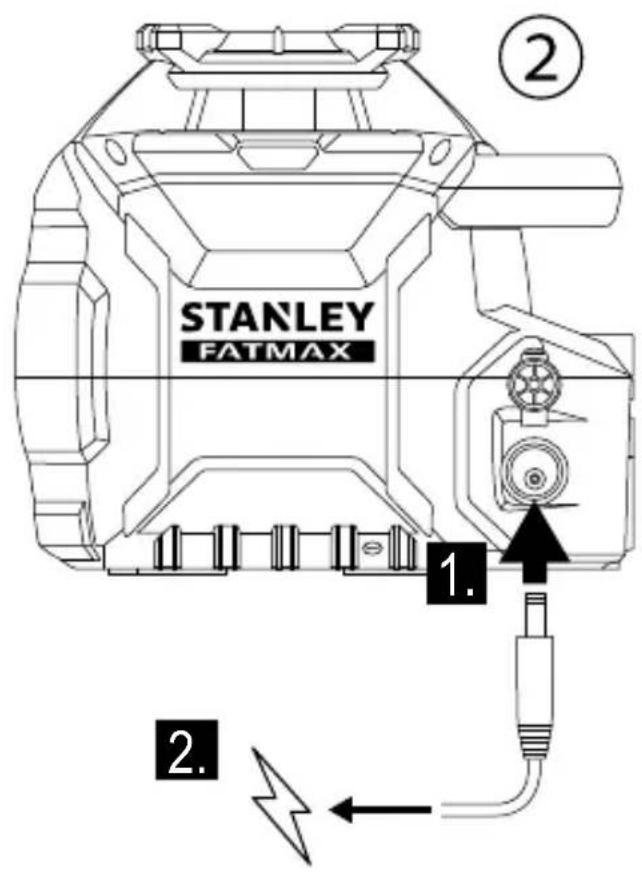
Charging the Li-ion Battery
RL 600L, RL 700L, and RL 750L-G
See Figure ②
-
Plug charging/power adapter plug into charging jack of laser tool.
-
Plug charging/power adapter into power outlet (110 V or 220 V) with appropriate plug receptacle.
The LED will light RED during charge.
- Leave battery to charge for approximately 7 hours to reach full charge.
The LED will light GREEN when charge is complete. - When battery is fully charged unplug the charging/power adapter from laser tool and power outlet.

WARNING: Charge laser only with the power adaptor supplied. Using any other type of charger may result in damage and/or personal harm.
Operating with Charging/Power Adapter
- Laser tool can operate while plugged into charging/power adapter.
- Functions and controls of laser tool are the same as when not plugged into charging/power adapter.
Using the Accessories

CAUTION: Do not leave the laser tool unattended on an accessory without fully tightening the mounting screw. Failing to do so may lead to the laser tool falling and sustaining damage.
Mounting Bracket
RL 700L and RL 750L-G
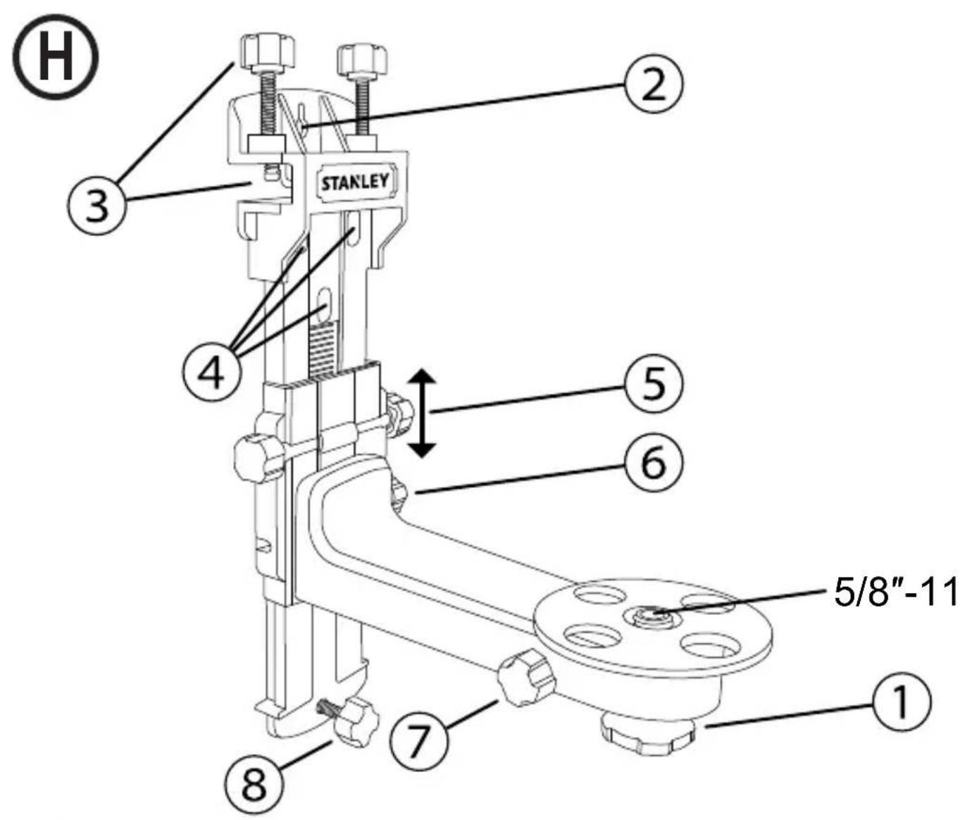
See Figure H
NOTE:
- It is best practice to support the laser tool with one hand when placing or removing the laser tool from an accessory.
-
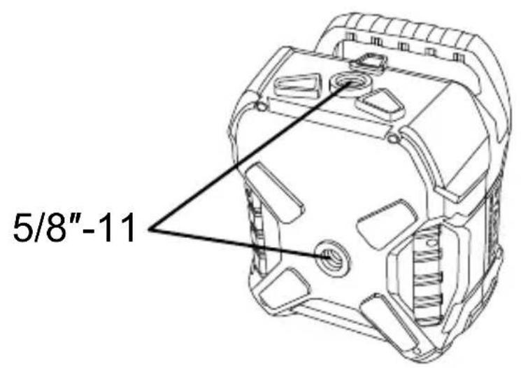
If positioning over a target, partially tighten the 5/8 -11 screw mount, align laser tool, and then fully tighten the 5/8 -11 screw mount.
-
Securely position the Mounting Bracket using one of the following methods:
-
Hang the Mounting Bracket from a wall using the Keyhole Slot (Figure ②).
- Attach the Mounting Bracket to a ceiling edge using the Ceiling Grid Clamp (Figure ③).
- Use the Keyhole Mount (Figure ④) with any compatible accessory.
2 Orient the bracket mounting surface so it is approximately horizontal.
3. Mount one of the laser tool's attachment points (Figure ①) to the bracket's 5/8 -11 mounting screw and tighten the tightening knob (Figure ①).
4. Use any of the following parts on the Mounting Bracket to further adjust the position of the laser tool.
- The Vertical Fine Adjust Knob (Figure ⑤) moves the laser up and down the vertical track. The Vertical Adjust Lock Knob (Figure ⑥) secures the vertical position.
- The Rotary Fine Adjust Knob (Figure ⑦) rotates the laser tool.
- The Wall Tilt Adjustment Knob (Figure ⑧) adjusts the angle between the Mounting Bracket and the wall.
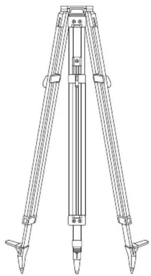
Tripod Mount
See Figure
- Choose a location for the tripod near the center of the area of interest where it will not be disturbed.
- Extend tripod legs as required. Adjust legs so the tripod head is approximately horizontal.
- Mount one of the laser tool's attachment points (Figure ①) to the tripod using a 5/8 -11 mounting screw then tighten the mounting screw.
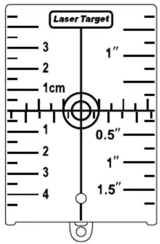
Target Card
See Figure
Some laser kits include a Laser Target Card to aid in locating and marking the laser beam. The target card enhances the visibility of the laser beam as the beam crosses over the card. The card is marked with standard and metric scales. The laser beam passes through the red or green plastic and reflects off of the reflective tape on the reverse side. The magnet at the top of the card is designed to hold the target card to ceiling tracks or steel studs to determine plumb and level positions. For best performance when using the Target Card, the front of the card should be facing you.
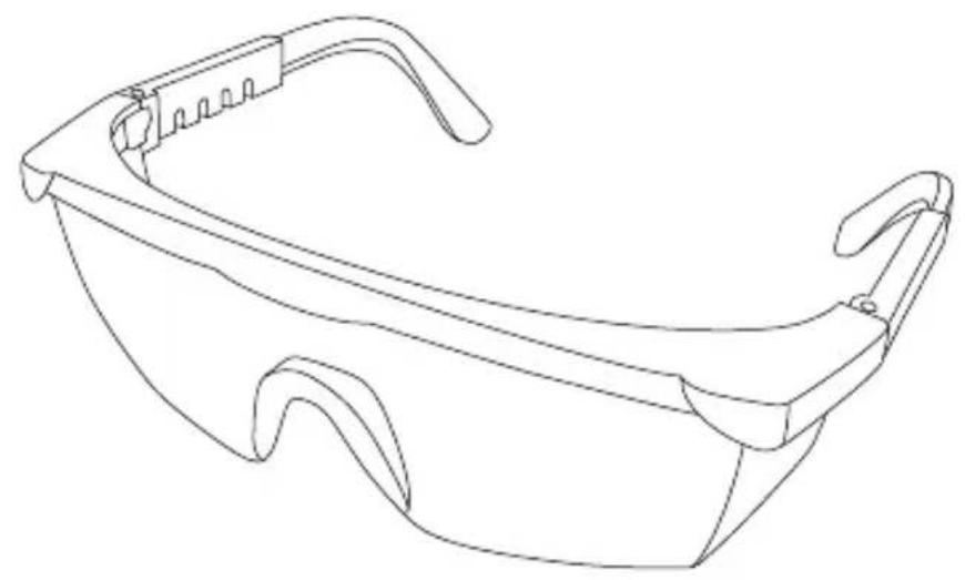
Laser Enhancement Glasses
See Figure
Some laser kits include Laser En hancement Glasses. These glasses improve the visibility of the laser beam under bright light conditions or over long distances when the laser is used for interior applications. These glasses are not required to operate the laser.

CAUTION:
These glasses are not ANSI approved safety glasses and should not be used while operating other tools. These glasses do not keep the laser beam from entering your eyes.

CAUTION:
To reduce the risk of serious injury, never stare directly into the laser beam with or without these glasses.
Turning the Laser On/Off
- Choose a smooth, flat, level surface to place the laser.
-
Depending on the desired application, position the laser horizontally (Figure A) or vertically (Figure B).
-
Press the key to turn the laser tool ON.
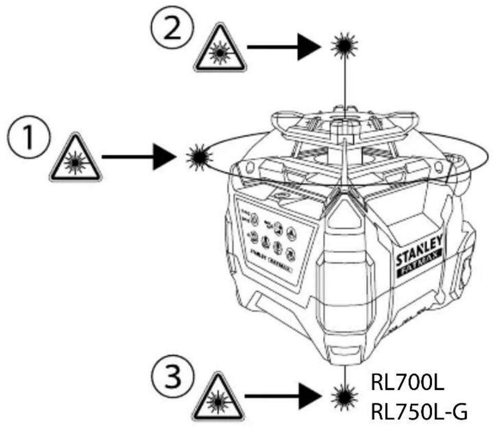
- The laser beings Auto-Leveling. During Auto-Leveling the LED flashes GREEN, the rotary laser (Figure A①) flashes, the Plumb Up Dot laser (Figure A②) flashes, and the Plumb Down Dot laser (Figure A③) is steady (if available).
- When the Auto-Levelling procedure is complete, the LED turns solid GREEN, the rotary laser rotates at the last used RPM setting, the Plumb Up Dot laser is steady, and the Plumb Down Dot laser (if available) remains steady.
NOTE: The laser tool's default Auto-Leveling mode can compensate for an uneven surface up to 5^ . If the laser tool is not level within 5^ , the GREEN LED and the RED LED alternately flash. Reposition the laser tool within the 5^ limit and allow Auto-Leveling to complete.
Auto-Leveling levels the plane of the rotary laser and sets the Plumb Up Dot laser and the Plumb Down Dot laser (if available) perpendicular to the rotary laser plane.
GB
Performing Accuracy Check and Calibration
NOTE:
- The laser tool is sealed and calibrated at the factory to the accuracies specified.
It is recommended to perform a calibration check before use. - Be sure to allow the laser tool adequate time to Auto-Level (< 30 seconds) prior to a calibration check.
- The laser tool should be checked regularly to ensure its accuracies, especially for precise layouts.
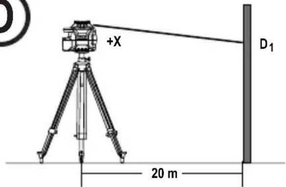
Horizontal Check
See Figure
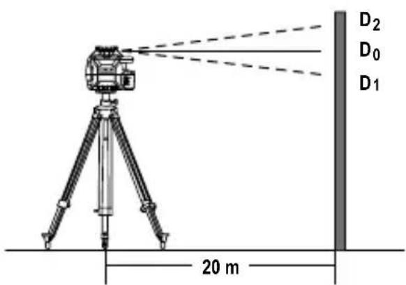
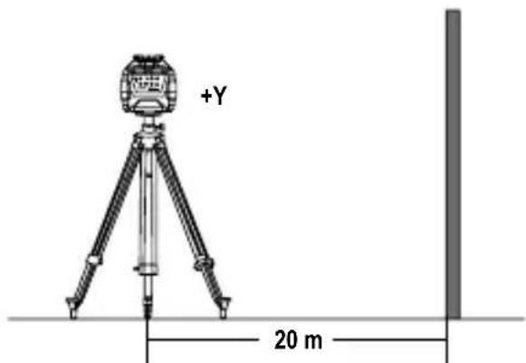
- Set the laser tool on a tripod 20m away from a wall with the "+" side facing the wall (Figure ①).
- Power ON the laser tool. Allow the laser tool to Auto-Level and be sure the laser is rotating.
- Mark a reference point "D 1" where the laser line appears on the wall. If available, use a detector to more easily locate the beam.
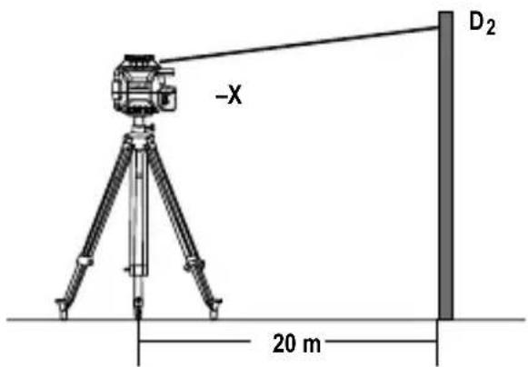
- Loosen the laser tool from the tripod and rotate the laser tool 180^ . The "-X" side should now be facing the wall (Figure ②). Mark a reference point "D2" where the laser line appears on the wall.
- Measure the vertical distance between reference points "D 1" and "D2" (Figure ①③).
- If the distance "D 1" to "D2" is < 2.0 mm , calibration is not required.
RL600&RL600L
If the distance "D" to "D2" is ≥ 3mm then calibration is necessary.
RL 700L & RL 750L-G
If the distance "D" to "D2" is ≥ 2mm , then calibration is necessary.
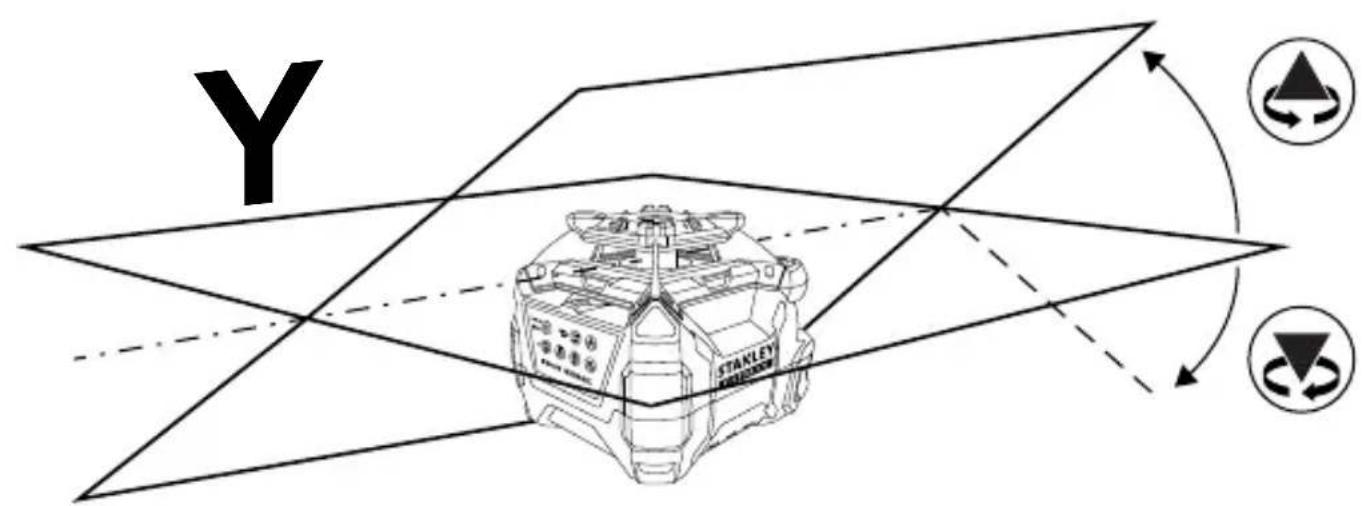
- Rotate the laser 90^ . Repeat steps 1. through 6. for the Y-axis. Replace "+" with "+" and "-X" with "-Y" (Figure ④).
Horizontal Calibration
See Figure
- Rotate the laser to the same position as step 1. of the Horizontal Check procedure (with the "+" side facing the wall).
- With laser tool powered OFF, press and hold the key followed by the key.
- Release the key and continue to hold the key for ≥ 3 seconds.
- Release the key.
- The 三 ~ 一 ~ ~ 二 ~ ED flashes GREEN when the laser tool is in X-axis Calibration mode.
- If necessary, adjust the X-axis by using the key and the key to align the beam with D0. D0 is the halfway point between the points D1 and D2 established during the X-axis check (Figure ③).
NOTE: Pressing the key or the key slopes the axis by 0.01^ (4.4 mm @ 25 m). Figure M illustrates how the arrow keys affect each axis.
- Press the key again to set the X-axis and proceed to the Y-axis adjustment. The ED flashes RED when the laser tool is in Y-axis Calibration mode.
- Rotate the laser to the same position as step 7 of the Horizontal Check procedure (with the "+" side facing the wall).
- If necessary, adjust the Y-axis by using the key and the key to align the beam with D0.D0 is the halfway point between the points D1 and D2 established during the Y-axis check.
- Press the key again to set the Y-axis and exit Calibration Mode.
Axis settings are now saved. Calibration Mode is OFF and the laser tool begins Auto-Levelling.
- Repeat the Horizontal Check procedure to determine if the calibration was successful.
If the laser tool can still not be calibrated after following the Calibration procedure, send the laser tool into an Authorized Service Center for repair.
Operating the Laser
Because the laser tool is a high precision instrument, it is preferable to use the remote (if provided) whenever possible.
Correcting a Tilt Warning
(Not available in Manual Mode)
If the laser is disturbed during operation the Tilt Warning LED changes from solid RED to flashing RED and the laser stops rotating and starts flashing. (Tilt Warning is on by default when the laser tool leaves the manufacturer.)
To correct a Tilt Warning:
- Check the laser tool to make sure it is positioned correctly.
- Press the key to reset the Tilt Warning.
- The laser Auto-Levels then begins rotating.
- Check the laser tool's alignment with the original target.
Turning the Tilt Warning Off
(Not available in Manual Mode)
- Power on the laser tool and wait for Auto-Leveling to complete.
- Press the key.
- The Tilt Warning LED changes from solid RED to off.
- To turn the Tilt Warning back on, press the key.
Changing the Tilt Warning Default Setting
- When powered OFF, press and hold the key then press the key.
- Release both keys.
- If the Tilt Warning LED is ON (red), the default Tilt Warning setting is ON. If the Tilt LED is OFF, the default Tilt Warning setting is OFF.
The Laser tool begins Auto-Levelling.
- Repeat the above steps to toggle the Tilt Warning setting ON/OFF.
Using Manual Mode
Manual Mode allows the laser tool to be placed at a range of angles. The laser does not Auto-Level and the Tilt Warning is set to OFF. Because Auto-Levelling is OFF, the beam is not guaranteed to be level.
- After powering on the laser tool, press and hold the key for ≥ 2 seconds to turn Manual Mode ON/OFF.
Note: When Manual Mode is activated, the rotary laser plane remains fixed with respect to the laser tool.
- Manual Mode is indicated by the flashing RED LED.

Note: Auto-Levelling is OFF in Manual Mode.
- The Laser tool can be manually positioned at any angle.
- Press and hold the key for ≥ 2 seconds to turn Manual Mode OFF. The laser tool begins Auto-Levelling.
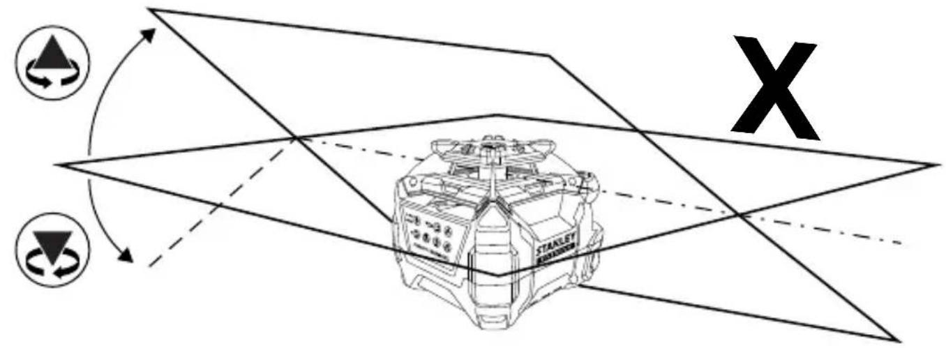
Using Manual Slope Mode
Manual Slope Mode allows the user to adjust the slope of the rotary laser in the X-axis and the Y-axis in a horizontal (Figure A) or vertical (Figure B) position.
- When powered ON, press the key once. Manual Mode turns on, indicated by the flashing RED Auto-Levelling is OFF and Tilt Warning is disengaged.
- A solid GREEN X/Y Select LED indicates X-axis adjustment is active. If X-axis adjustment is not required, proceed to Step 5.
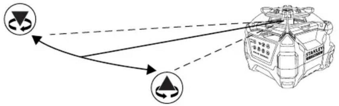
- Press the key to adjust the X-axis up. Press the key to adjust the X-axis down. Figure ① illustrates how and affect each axis.
NOTE: Holding on down slopes the axis continuously. The rate of slope change increases over time. Pressing or once adjusts the slope by 0.01^ .
- The X/Y Select LED will flash GREEN when the maximum slope angle is reached. The axis will not move any further in the X direction.
- Press the key again to set the X-axis and activate Y-axis adjustment.
- A solid RED X/Y Select LED indicates Y-axis adjustment is active. If Y-axis adjustment is not required, proceed to Step 9.
GB
- Press the key to adjust the Y-axis up. Press the key to adjust the Y-axis down. Figure ⑧ illustrates how and affect each axis.
NOTE: Holding or down slopes the axis continuously. The rate of slope change increases over time. Pressing (A) once adjusts the slope by 0.01^ .
- The X/Y Select LED will flash RED when the maximum slope angle is reached. The axis will not move any further in he Y direction.
- Press the key again to set the Y-axis. The X/Y Select LED #tns off.
- The X-axis and Y-axis are now set to manually adjusted slopes. Use the laser in Manual Slope Mode.
- To turn Manual Slope Mode OFF, press and hold for ≥ 2 seconds. When Manual Mode is turned OFF, the LED stops flashing and the laser tool begins Auto-Levelling.
NOTE: To change between horizontal and vertical positions the laser tool must be powered OFF, repositioned, and then powered ON in the new position.
Changing the Rotation Speed
Press the Rotation Speed Key cycle through the available speed settings from fastest to slowest to Spot.
| Available Speeds | ||||
| RPM: | 600 | 300 | 150 | 0 (Spot) |
Using Spot Mode
Spot mode halts the rotary laser's rotation and allows the user to manually adjust the angle of the "Spot".
- Use the key to cycle to the Spot setting (0 RPM).
Use the key to rotate the Spot counterclockwise. Use the key to rotate the Spot clockwise.
NOTE: Holding down the key or the key will rotate the Spot continuously. After holding down an arrow key for several seconds, the Spot flashes 3 times and then rotates at a faster rate. A single press of an arrow key will rotate the spot 0.5^ .
Figure illustrates how the arrow keys affect the Spot rotation.
Using Scan Mode
RL 700L and RL 750L-G
Scan Mode limits the rotary laser's projection to a set scan angle and allows the user to manually adjust the position of the scan.
- Press the key to cycle through the available Scan angles (10^ / 45^ / 90^) .
Use the key to rotate the Scan counterclockwise. Use the key to rotate the Scan clockwise.
NOTE: Holding down the key or the key will rotate the Scan continuously. After holding down an Arrow Key for several seconds, the Scan flashes 3 times and then rotates at a faster rate. A single press of an Arrow Key will rotate the Scan 2.0^ .
Figure ① illustrates how the arrow keys affect the Scan rotation.
- Press the key to turn off Scan Mode and return to the last used speed setting.
Using the Remote Control
RL 600L, RL 700L, and RL 750L-G
All available functions and modes are accessible through the keys on the Remote Control with the exception of toggling the Tilt Warning ON/OFF and powering ON the laser tool. (The laser tool can be powered off.)
Using the Detector
The Detector allows the user to determine the location of the laser when distance or lighting conditions make the laser difficult to see.
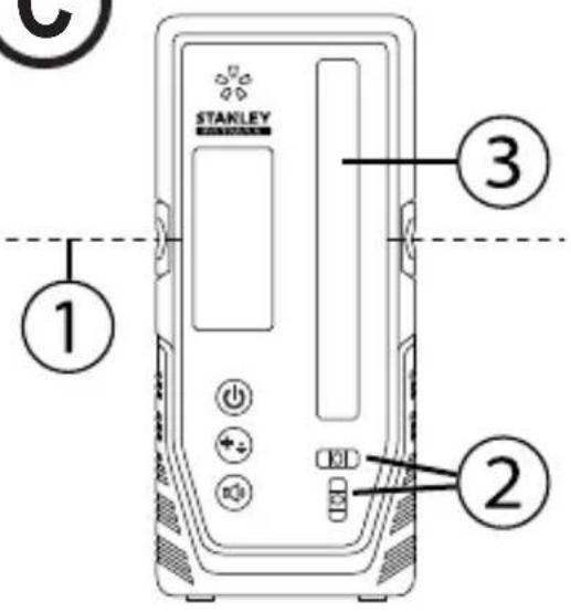
Detector Keypad

Power ON/OFF Key

High/Low Accuracy Key

Speaker Volume Key
Detector LCD Icons

Laser Detected - Reference Line Higher than Laser Beam. Move the Detector the Direction Shown (Down).

Laser Detected - Reference Line Lower than Laser Beam. Move the Detector the Direction Shown (Up).

Laser Detected - Reference Line in Line with Laser Beam Reference Level.

Buzzer Volume - Loud/Soft/Mute.

OFF

Low Accuracy Setting

High Accuracy Setting
Detector Setup
(The Detector can be used in hand or with optional clamp to mount the detector to a measuring rod, pole, or similar object)
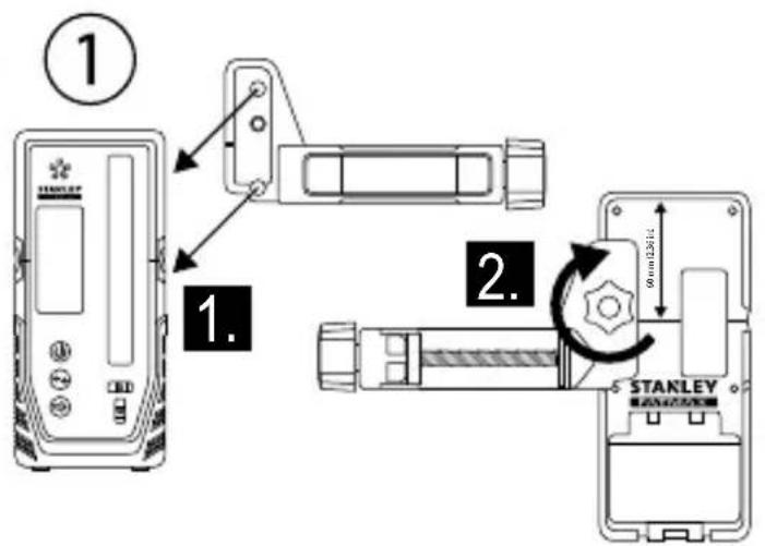
Mounting Clamp onto Detector
See Figure ①
- Guide the clamp onto the detector using the alignment hole.
- Tighten the fixing screw.
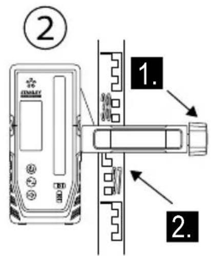
Mounting Clamp onto Level Staff, Pole, or Similar Object
See Figure ①②
- Loosen tightening knob.
- Place onto level staff, pole, or similar object.
- Tighten tightening knob to secure the clamp.
-
When locating reference level, loosen clamp to allow for up/down positioning.
-
When reference level is found, tighten knob again to secure the Detector. Read the position shown at the Reference Line (Figure ①) edge of the clamp.
Operating the Detector
(See Keypad and LCD Descriptions for indications during operation)
Powering on the Detector
- Press the key to turn detector ON.
- When powered ON, the entire LCD will momentarily display all icons (use this to ensure the LCD is functioning correctly).
- Press and hold the key for ≥ 2 seconds to turn the detector OFF.
NOTE: The detector will automatically power OFF after not detecting a laser beam for 10 minutes. To power ON again, press the key.
Illuminating the Detector LCD
- When detector is ON, press the key to turn ON/OFF LCD illumination.
NOTE: The illumination will automatically turn OFF after 60 seconds of not detecting a laser beam or having a key pressed.
Adjusting the Detector Accuracy
- When powered ON, press the key to toggle the accuracy setting between HIGH and LOW.
- The default accuracy setting is HIGH.
NOTE: Use the LOW accuracy setting when:
- The HIGH accuracy setting is not needed.
- A stable reference level cannot be obtained due to vibrations.
- Heat haze interferes with the laser beam.
Adjusting the Detector Speaker Volume
- When powered ON, press the key to toggle through the volume settings (LOUD/SOFT/MUTE).
- When powered ON, the default volume setting is set to LOUD.
GB
Detecting Reference Level
- While powered ON, position the detector where the laser beam is projected.
- Use the detector's bubble vials (Figure ②) to maintain a level plane.
- Point the laser reception window (Figure ③) toward the laser beam source. The reception window must face within 40^ of the laser source.
- Use the "Laser Detected" icons on the LCD to align the Reference Line (Figure C①) with the laser beam.
NOTE: If the speaker volume is ON (LOUD/SOFT), a audible tone also assists with) aligning the detector. A fast beeping tone signals the detector must be moved down. A slow beeping tone signals the detector must be moved up. A steady tone indicates the laser beam is aligned with the Reference Line on the detector.
| Steady Tone Aligned with Reference Line |
| Fast Beeping Tone Move Detector Down |
| Slow Beeping Tone Move Detector Up |
- When the laser is aligned with the Reference Line, mark that position.
NOTE: If the top of the detector is used as a marking location, reference the back of the detector for the measurement compensation value.
Maintenance and Care
- When the laser is not in use, clean the exterior parts with a damp cloth, wipe the laser with a soft dry cloth to make sure it is dry, and then store the laser in the kit box provided.
NEVER use solvents to clean the laser. - Do not store the laser at temperatures below -10^ or above 40^ .
- To maintain the accuracy of your work, check the laser often to make sure it is properly calibrated.
- Calibration checks and other maintenance repairs may be performed by STANLEY service centers.
Laser Tool
GB
Specifications
| RL 600 RL 600 | RL 700L RL 750L-G | |||
| Horizontal Rotary Accuracy:* at 20°C | +/-2.2mm @30m +/- | -2.2mm @30m +/-1.5mm @30m +/-1.5mm @30m | ||
| Vertical Rotary Accuracy:* at 20°C | +/-3.0mm @30m +/- | -3.0mm @30m +/-3.0mm @30m +/-3.0mm @30m | ||
| Plumb Up Dot Accuracy:* at 20°C | +/-4.4mm @30m +/- | -4.4mm @30m +/-3.0mm @30m +/-3.0mm @30m | ||
| Plumb Down Dot Accuracy:* at 20°C | N/A N/A +/-8.7mm @30m +/-8.7mm @30m | |||
| Compensation Range: 5° 5° 5° 5° | ||||
| Slope Range: ±10% (dual axis) ±10% (dual axis) ±10% (dual axis) ±10% (dual axis) ±10% | ||||
| Minimum Slope Increment: 0.01°(4.4mm @ 25m). | 0.01°(4.4mm @ 25m). | 0.01°(4.4mm @ 25m). | 0.01°(4.4mm @ 25m). | 0.01°(4.4mm @ 25m). |
| Scan Range: 10°/ 45°/ 90° ±20% | 10°/ 45°/ 90° ±20% | 10°/ 45°/ 90° ±20% | 10°/ 45°/ 90° ±20% | |
| Working Range Diameter with Detector: | ≤ 600 m | ≤ 600 m | ≤ 600 m | ≤ 600 m |
| Leveling Time: | ≤ 30 seconds | ≤ 30 seconds | ≤ 30 seconds | ≤ 30 seconds |
| Rotation Speed:* at 20°C (room temperature) | 0/150/300/600 rpm +/- 10% | 0/150/300/600 rpm +/- 10% | 0/150/300/600 rpm +/- 10% | 0/150/300/600 rpm +/- 10% |
| Laser Class: | Class 2 ≤ 1.0mW(IEC 60825-1:2014) | Class 2 ≤ 1.0mW(IEC 60825-1:2014) | Class 2 ≤ 1.0mW(IEC 60825-1:2014) | Class 2 ≤ 1.0mW(IEC 60825-1:2014) |
| Laser Wavelength: | 630nm - 680nm | 630nm - 680nm | 630nm - 680nm | 630nm - 680nm |
| Operating Time: | ≥ 30 hours | ≥ 40 hours | ≥ 40 hours | ≥ 30 hours |
| Recharge Time: | N/A | ≤ 7 hours | ≤ 7 hours | ≤ 7 hours |
| Power Source: | 2x D-cell alkaline | Li-Ion Battery | Li-Ion Battery | Li-Ion Battery |
| IP Rating: | IP54 | IP66 | IP66 | IP66 |
| Operating Temperature Range: | -10°C ~ +40°C | -10°C ~ +40°C | -10°C ~ +40°C | -10°C ~ +40°C |
| Storage Temperature Range: | -10°C ~ +40°C | -10°C ~ +40°C | -10°C ~ +40°C | -10°C ~ +40°C |
Remote Control
Type:
Indoor Operating Range:
Power Source:
Infrared
15 m
2 x AA Batteries (Alkaline)
Detector
Levelling Accuracy (High)
Levelling Accuracy (Low):
Laser Reception Window Width:
Working Range Radius:
Bubble Vial Accuracy:
Operating Time:
Auto Power Off (with No Signal Detected):
Power Source:
IP Rating:
Operating Temperature Range:
Storage Temperature Range:
≤1mm
≤2mm
55mm
≥ 300m
3^ / 2mm
20 h
10 min
2xAA
IP66
-10°C to +50°C (+14° F to +122° F)
-25°C to +70°C (-13°C F to +158°C F)
Notes
Inhalt
-10°C to +50°C (+14° F to +122° F)
Power led & Handmatig led
- X as aanpassen kalibratie stand.
Knippert rood
-
Y as op maximaal toegestane helling in de helling stand.
-
Y as aanpassen kalibratie stand.
Veiligkeit van de batterijen
PA/AV-knapp for ström

PÄ/AV-knapp für lutningsvarning

Knapp for rotationshastighet

Knapp med uppátpil (moturs)

PA/AV-knapp for ström

Knapp for hog/lag noggrannhet

Knapp for hogehtalarvolym
SE

Laseren starter selvretting.
Tast for hoy/lav noyaktighet

Volumtast høytaler
Detektor LCD-symboler

H M E I H
H kalutepn npaktikn evai va unoatnpizrto epyaiao laizep 1Eva xepi otav tonotheite n apaipite to epyaiaio aicep 1Aeva aesouap.
Av toothei Te naww ano eva oToxo, ophiEevmuepi Tn otepewon Bi0a 5 / 8^ - 11 , eUthuypaumotro epyaaleio hεcp kai karomiv ophiEe nnpwoTn otepewon Bi0a 5 / 8^ - 11
- TToT@TneTe aOaAeia To otnpiyua EyKatataoans XpnoiOttoWvTac mia atio tic npakatw e06ouc:
Avapntote to otnpiyya Eykataaotaans eEvav toixo xpnoiopoioiwtaTn oxioun oxnpatoc kAeipapotputtac (Eikova H2).
TO OTnpiyMa EYkataoTaonc OEvA Akpo opoqnc XpnoiOIOIOWVtac To OphiYKTnpa DIKTuWmuOg opoqns (Eikova H③).
Xpnoiopoioiote tn otepeoan eow ontc oxnatoKlaedapotpuTAC (Eikova H4) e otioobntote oubetao aoeouap.
-
Ipoosavatoiaote nvy eivapaveia ykataotaonc tou Otnpiypatoc wote va eivai TepiTou opizovia.
-
TToTtnte eva ato ta anueia ouvdoanc tou epyaleiou EiEep (Eikova ①) stn biDa eykataaotaans 5/8"-11 tou otpiymuoc kai oigre tn aBn ouoqigns (Eikova H①).
-
Xpnoiopoioane oioohtote ato ta akoloutheta apntmuata naw oTo ot npiyya Eykarotaon yia va Tpoapapoae TepaTepw Tn theon Tou epyaleiou aeIep.
To koupiTi Ka8eTnC iKpoppuOiOng (Eikova H5)
muakivei to aeIep TPOc Ta TAVW KAI KATU eTI nC
Ka8eTnC payac. To koupiTi aQaAionc Ka8eTnc puOuianc
(Eikova H6) aQaaiZeI TNV Ka8eTn 0eOn.
To koupi Tepoiopiknc iipoppuoianc (Eikova H⑦) TepiOppei to epyaeeioeep.
To koupi npoapoyn kianc toixou (Eikova H8) npoapocet n yovia avapeo a oto otnpiypa Eykataotaonc kai oTOv toxO.
Bao n tripioobou
BA.Eikova K
TYTO POKNY USCHOVEJTE

VAROVANI:
Prid pouzitim tohoto vyrobku si peclive prectete BezpecnostniPokyny a Uzivatelskou prirucku.Osoba odpovedna za tento pristroj musi zajist,aby vsichni uzivatelpeochopili adodrzovali tyto Pokyny.

UPOZORNENI:
Je-li tento laserovy pristroj pouzivan, daveje pozor, aby vysilan'y paprsek nemiril primo do oci. Dlouhodobe pusobeni laseroveho paprsku na vase oci muze byt nebezpecné pro vas zrak.

UPOZORNENI:
TYTO POKNY USCHOVEJTE

VAROVÁNÍ:
AkkymyJIaTOpHbIe 6aTapeN n NHTaHne
YctaHObKa 6aTapei
YcTaHOBka aKKymyIaTOPHO6aTapEn Na3epHOro INHCTpyMeHTa
RL600
CM.Puc. ①
- HaxmTe Ha KpbIuKy 6aTapeHoro OTcKa Nn3BneKeITe ee.
-
YctaHOBtTe DBe HObIX 6atapeKu Tuna «D». Ipn yCTaHOBKe 6atapeek B INCTpyMeHT COBJIOdaIte npabINbHyIO NOJRAHOCtB.
-
Hadejko 3akpoTe n 3aФNKcnpyTe KpbIuKy 6aTapeHoro OTEka.
YcTaHOBka 6aTapen nyIbTa dNCTaHcNoHHoro ynpabNeHn
RL 600L, RL 700L, n RL 750L-G
CM.Puc. ⑥②
OTKpoTe 6aTaapeHbI OTcEK, CHB KpbIshKy.
2. yctahOBtTe DBe HOBbIe 6aTapeKu AA. Pn yctahOBKe 6aTapeek B INHCTpyMeHT co6JIoDaIte npabNbHyIOIPOJPHOCTb.
3. HadejHo 3aKpOte n 3aФnKcpyTe KpbIuKy 6aTapeHoro OTceKa.
YctahOBka 6atapei dTeKTopa
CM.Puc. ⑥ 2
- OTKpoTe 6aTapeHbIX OTEcK, NOdHbKpbIiKy.
- yctahOBHTe DBe HOBbIe 6aTapeKu AA. Ipn yctahOBKe 6aTapeek B INCTpyMeHT co6nOdaTe npabNbHyIOJIpaHOCTb.
- HadejHo 3aKpoTe n 3aФNKcpyuTe KpbIuKy 6aTapeHoro OTceKa.

OCTOPOXHO!
Co6nHOaune npaeunbHyo nonpHocmb (+) u (-), yka3aHHyHa bamaepuHOM omceke. BamapeukdoJXhbl 6bIMb odHOo muna u oIadamb oUHaKOBou EMKOCMbIO. He ucnObn3yume bamaeukcpa3hbim ypoBEm 3apda.

3apraKa IOHHO-NTHeBOB 6aTapeN
RL 600L, RL 700L, n RL 750L-G
CM.Puc.⑤②
1.ПОДКИJOHTeIteKep aanTepa 3apRKn/NITAHINK 3apRHOmy rHe3dy na3epHOrO nHCTpyMeHTa.
2.Подкночte aanTeep 3apRkn/ntaHnK po3eTke (110Bnnn 220 B).
Bo BpemcBToaNoi. 6yTtopebKpaChbIM UBeTom.
- Octabte 6aTapeo 3apjkaTbcn np6nnteNbHO 7 yacOB noIHHoro 3apya.
CBeToNDHaHHTMraTb3eJIeHbIM,KOrda3aprKa 6yDen3aBepueHa.
- Korda 6atapey 6ydt nonHocbIO 3apxkeHa, OTKIOHTe aanTep 3apRKn/NTaHnO T po3ETK.

OCTOPOXHO! 3apxaaime naepHb uHcmpymem monko c nomoubdo adanmepa, exodaezo e komnkemauho. Mcnoh3oaehue kaoo-nuo dpye2o2 3apdnozycmpoucmea moxem npueecmu K noepexdehuu u/Unu luuchbIM mpaamam.
3Kcnpnyatauia aanterpa 3apdKn/ nHTaHn
- Na3epHbI INHCTpyMeHT MOXeT pa6oTaTB npn NOkNIOueHN K aanTepy 3aprKn/NTAHNA.
-Функионироваиме ИЗлем entы упаьеня пазерно нстумета салогчы Tem, КOTьп ecnoьзуOTс, кога адаNTep зардк/NITaHЯ He NOДКИQUЕH.
3Kcnpnyatazaia npHaJneXHocTei

BHIMAHHE! He ocmaenlme naepbui uHcmpyMeHm 6e3 npucmopha Ha npuaadnexknocmu, ecnu Kpenexhui Eunm He 3amrhym Hadnexkaum oba3om. Hecobkohe daHHo mpe6oBaHua MOxem npueecmu k naedeHIO naephozo uHcmpyMeHma, e pe3yIbmae yeo OH ydem noepekdeH.
KpenexHbI KPOHHTeH
RL 700L n RL 750L-G
CM.PnC. H
PIMMEYAHNE.
-
Ycmahaauea u cHMa naepbui uHcmpyMeHm cnpuHaadnHexHoCmu, peKomeHyemra HadeXho ydepxuabMb eO odHou pykou.
B cnyuae 3akpenneHua had ueIbIo 3amHume buHmoyu onopy 5/8"-11, ycmahoeume uHcmpymem e Heobxodumom noIoxehuu, 3aem nonHocmbu 3amHume buHmoyu onopy 5/8"-11. -
Hadejno paonoloxnTe KpeeKhB KPOHHTeH OdHM n3 cnedyuux cnoocob:
-
NoBecbTe KpeNexKbI KpoHHTeIN Ha CteHe c NOMOu bIO na3a (Pnc. H②).
YCTAHOBHTe KpeEnXhbl KPOHHTeHN Ha KpaIO NOTOJka C NOMOUBIO 3aXIMOB DnI NOTONOCHORO KApKACA (Pnc. H③).
BocnoIb3yITeCb KpeJIeHNHeM COTBepCTHem (Pnc. H4) c IHO60nOxOJaUe npHaJNeXHOCTbIO. -
PacnoIoxnTe KpeNexHbKPOHHTeH, YTO6bI OH 6blI pacnoIoxHe npu6n3nteBHO B TOpu3OHTaJIbHOM NOIOxHeHm.
-
YctahOBHTe Ody n3 Toeyk KpeHneHnna3epHoro HCTpyMeHTa (Pnc. ①)Ha BnHTOBe KpeHneHne 5/8"-11 n 3aTaNHe pyKy (Pnc. ①).
4.ДядьншeyperynipOBKINnoJoxeHna3epHOrO HCTpyMeHTaNCNoB3yIteJIIO6OIN3CNeDyUxK KOMNOHETOB.
PyuKa ToHkO BepTnKaJIbHO nperyInpOBKn (Pnc. H5) nepemeaaet Ia3epHbIn INCTpyMeHT BBePx IN BnI3 BDOJIb BepTnKaJIbHO npOxxKn.PyUka PnKcaunBepTnKaJIbHO nperyInpOBKn (Pnc H6) pIKCpyeT BepTnKaJIbHOe noIOXHe Ia3epHoro INCTpyMeHTa.
Pyka ToKoP perynipOBKn BpaueHn (Pnc. ⑦) NOBOPaUNBaET na3epHbI INCTpyMeHT.
PyuKa peYnIPOBKn HAKNoHa NO OTHoSeHnIO K CTHe (Pnc Hx8) peryIpyeT yroJ MExNy KpeEnexKhbIM KpoHHTeHOM N CTHoH.
Tpehora
CM.Puc. K
- YctaHOBITE TpeHory IIO CEHTpy 3OHBI IIpIMHeHnRA3epHOro HNCTpyMeHtA, rDe OHa He 6ydt CnyaHNo CMeueHa.
- BbDnBHe HOKKn TpeHOrn B Heo6xOaMoe NOXKeHne. OtperynpyTe HOKKn TaKIM 06pa3OM, YTO6bl ROJOBKa TpeHOrn HaxOaNacb npu6n3nteNbHO B rOpu3OHTaNbHOM NoIoxKeHn.
3.YcTaHOBnTe OndHy n3 ToueK KpeIeHnJa3epHOro HnCTpyMeHTa (Pnc. ①)Ha TpeHore C NOMOuBbBO BnHTOBORO KpeIeHn5/8"-11 n3aTaNHe KpeEeKhBn BnHT.
MnweHb
CM.Puc.
HekotopbIe KOMPnEKTaun Ia3ephBIX INCTpyMeHTOB BKIOUaOT MIIeHb dIy Ia3epa, KOtopaanomoraet HaITN OTMeNTb Ia3epHbI JyU. MIIeHb yLyuHaAET BNDIMOCbI Ja3epHoro Jyua.
Ha MIIeHb HAnecea SHkaJaB MTePnuecKo N 6pntAHcko CnCTeme MeP. Ja3epHbI JynpoxOHT Upe3 KpaCHyo N 3eJeHyIO pIaCTMaCCy IOptpKaEtC T OT OtpaKaIoSe IeHTbl, paCNoJooKeHHoB B 3adHe YactN. MarHIT B BepxHe YactN MIIeHN IpeDHa3NaueH dIy KpePnEHHa MIIeHN K NOTOnOCHOMy Kapkacy IIN npOphiM dIy ONpeDeJIeHHa YPOBHi N OTBeCa. Ipn IcNoJIb3OBAHm MIIeHN NpeDnra ee Yactb DoJXHa 6bItb HanpaBHeHa Ha Bac.
OuKn dIyucnEnHbUdHMocTN Ja3epHoro Lyya CM.Pnc.
HekotopbIe KOMnJIeKTAuIN Ia3epHBIX INHCTpyMeHTOB BKJIOUaIOT OcKn IyCNIeHNr BvIMMOCTN Ia3epHO rO Lyua. 3TN OcKn yBeJIuINBaIOT BVIMOCtB Ia3epHO rLyuBa B rPKx NOMEueHNr Ha 6oJIbXnx paCToRHaNX. DaHHbIe OcKn He o6raTeJIbHbI dIra 3KcPnyatauIN Ia3epHO rHCTpyMeHTa

BHIMAHHE!
Oyu He yraHcma 3aumhbuM u He UmeHm
ymeepxdeHn ANSI, noommy ux ekcnnyamaucn C
dpyzmu uncmpyemhamu 3anpeueHa. Ocu He
3auiauom 2na3a om nonadHure Hux naepHBix nuye.

BHIMAHHE!
Bo u36eXaHue nonyuHua mJxKebI xmpaM, He cmompume npraMo 8 na3epHbI pyu, eHe 3aeucumocmu om Hauuur 3mux Oyko8.
EcInpacCTOJHnEOTD 1>DO D2>coCTaBJIeT ≥2MM,Heo6XoJIMO BbIIOJIHTbKaJIINOpOBKy.
TOpn3oHTaJIbHaJaKanI6pOBka
CM.Pnc.
- ПовернITE Лазерньи ИСТумЕВ TO_JE NOLOKEHNE, KOTOPOE ИСПОЛБЗОВАЮСБ B WARE 1.поцедрbl ropиэтально поверки (сторна «+X» Должна 6ытб habравлеса на CTehу).
2.Пи ВьклочenvHom Ja3epHOM HCHtpymeTe HaKMITE udepxuBaTe KONky TaTEM KONky . - OTnycTnte KhoNky npoJOnJaTe ydePknBaTb KhoNky B TeueHne ≥ 3 c.
- OTnyctnte KhoNky
- Korda napehbl mHCTpymeHT haoDNTcB pexime KaIb6pOBKn ocN X, CBeToNDmMaaet 3EJIeHbIM CBETOM.
- EcnHHeo6xOaHMo,OTkAIn6pyTe oC X c NMOuBIO KHONK H KONKn ITObbl BbIpaBHaTb Na3epHbI Nyc TToKo D0.D0-3to ToUka,HaxOJaUaCra NocepeDHe MeJy D1u D2,OTMeueHHaB X Oe npOBepKn ocX (Pnc ③).
NPMMEAHHE. HaxaTne KhoKn N Mameet HaKIOH OcHa 0,01° (4,4 MM Ha pacCToHn 25 M). Ha Pnc. M OTO6paKeHo, KaK HaxaTne KHOONK BnIeT Ha KaKdyO ocB.
- HaxMMTE KONKy BTOBPOH, YTO6bI COXPAHHTb HAcTPOIKN OCN X N HauaTB peYINPOBKY OCN Y. Korda Na3epHbI INCTpMENT HAXOINTCB PEXKIME KAIN6P0BKN OCN X, CBETODIO MFAEET KPACHbIM UBeTom.
- ПовернITE Лазерьи Иструмент в.To Кплохене, kotopooe nCnoIb3OBAJIOCB B WARE 7.npoceDypbl ropn30HTaJIbHoJ npOBepK (cTOpOHa «+Y»doJxHa 6bITb HaprabHeHa Ha CTeHy).
- EcHn Heo6xOaHMo, OTKaIIN6pyTe oCb Y c NOMOuK HONKn U KHOKN TO6bl BbipABHrTb Ia3epHbI JyC TOTKO D0.D0-3TO TOUka, HaxOJaAcaRnOcepeDHe MeKdy D1N D2, OTMeueHHaB XoJe npOBepKn OcN Y.
- Haxmte KhONky BTOpHo, YTObI COxpaHHTb HAcTpoiKN OcN Y INoKHyTb peXIM KaIN6pOBKn.
HactpoynocoxpaHebl.PekimkanibpobKn BbIKIOaetcna3epbIINHCTpyMeNT nepexOHTBpeKIM CaMOBbIPAHBNAHIA.
- NobtopTe npoceDpyr ropn30HTaIbHoi npOBepKn, YTO6bl npOBepuTb npaBnIbHoCTb KaIIb6pOBKn.
Ecnu na3epHbI uHcmpymHe moxem 6bimb omkaubpoehn hadJekaum oba3om e coomeemcmeu c npoedypou KaUbpoBku, omppaBme na3epHbI uHcmpyme h aBmOpU3OaHHbI cepucbI ueHmp Ha pEmHm.
3KcPnyatauJa3epHoro HHCTpymEnTa
IockoNbky Ia3epHbI INHCTpyMeHT YBnETCB BICOKOTOHybIM INHCTpyMeHTOM, NO BO3MOxHOCTn peKOMeHNyETcN cIOJb3OBAtB nyIbT dNCTaHNoHHOrO ynpaBHeHn (pnp HAnuHn).
YcTpaHHe npeDynpexKdEHNaKJIOHe
(HeoctynhoBpyHOMpeKmE)
EcIn na3epHbI nHCTpyMeHT 6bl 3aTeB XoDe pa60TbI, CBeToNDIOcMeHReTc c NoctOHHo rOpAeero KPACHOFO CBeta Ha mraOnuIK PACHbI uBET, na3epHb Iy npKepaaaet Bpaaatbcra HauHaet MraTb. (PpeDynpExdHe O haklohe BKnUoyeho no yMOnuHaHIO, KOrda na3epHb I NCHtpMeHT NOKndaet 3aBOd.)
YcTpaHHeNnIpeDynpEckEnnO hKnloNe:
KHONKA BbICOKO/HH3K08 TOUHOCTN

Khonka rpoMkoCTn DHHaMka
3нauки XXK-эКрана DeTeKTopa

Ja3ep 6hApxhen -OnopHnA JINnBbIe Ja3epHoro Jyua. IpeMeCTnte DeTeKTop B yka3aHHom HappaBHeHH (BHN3).
Ja3ep 6hApxhen -OnopHnHnHnKe Ja3epHoro LyuHa. IpeMeCTIe DeTeKTop B yKa3aH-Hom HapBaJIeHN (BBePx).
Ja3ep 6bHApxKeH - OnopHaJINnIa3epHbI JyU COBnaIaOT.

「pomkoctb 3yMMepa —「pomk/THXn/6e3 3Byka.
BbIKI.

Hn3ka HacptpoKa TOnHOCTN

BbICOKa HacTPOKa TOnHocTn
YcTaHOBka DeTeKTopa
(Демекр можно удахьамь в руке улс nomоцьдонл humьноз зжumsдя усановке на мерhoшpeke/ cmonбе unu noxokem npedmeme)
YcTaHOBka 3axnma Ha deTeKTop
CM.PuC.①
- YctaHOBtE 3axm Ha DeTeKToP C NOMOu bIO OTBepCTnI BbipabHbAHnI.
2.3aTaNHTKe KpenexHbI BnHT.
YcTaHOBka 3aXIma Ha HnBeJIuPHyIO peKy, CToIb6 NII NOXOXN IpeDMET
CM.PnC.①
- Ocna6bte pyky 3aTjxKn.
- YctahOBInTe Ha HnBEnHpyu peKy, cTOn6 nI IN NOXOKM ppeMet.
-
3aTAHHTe pyHKy 3aTAKK, YTO6bI 3aKePENITb 3aJIM.
4.Пи расложени onopHOrO ypoBnO cna6bTe 3axmДпяperynipOBKn BBepx/BHN3. -
Поссе onpedenenno onopnor ypoBna ChOba 3aTaNHe pyky, YTO6bI 3akpenTb detekTop.CM.nonoxeHne,nokazahHoe OTHOCHTeNbHO ONpHoN mHn (Pnc. ()1) kpa3axkma.
3KcPnyatauia deTeKTopa
(B xode 3kcnnyamauuu cm. onucahue Khonoohn naHenu u KK-ducnner)
BkIouehne nHTaHn deTeKTopa
- HaxMnte KhONky BkHIOUeHnI deTeKTopa.
-При Вкючим Ha XX-Dиспee краTKOBpeMeHNo OTOбрахаOTcBce 3начки (ЗTo Heo6xOДМо Дл поверкН НдnexkaцeroФункционрованя XX-Dиспя).
-ДЯВыклоченя DeTeKTopa HaxMITE ydepxmbaTe KHONky B TeueHne ≥ 2 c.
PIMMEYAHNE. DeTeKTop aBtOMaTnueckN OTKHOnHTcNocNe TOrO, KaI Na3eRbI JyH He 6yTe oBhApXKeH DoJIbWe 10 MmHT. YTo6bI ChOba BKNIOHTb yCTPOINCTBO, HAXMITE KONKy
PoiocBetka KK-dncnner detektopa
- Pn BkIIOueHHOM DeTeKTOpe HaxMMte KHOKNy BkIOueHnBbIKIOueHn NOcBeTKN KK-dncnner.
IyIbT InCTaHcNoHHOrO ynpabLeHnA
Tn:
Pabouyn dana3oH TempepaTbp NomeuEHHx:
VCTOCHNK NITAHIA:
Hnphpaekpacbni
15 MM
26aTapeiKaA A (IeIoUHbIe)
TeKTop
TIETO POKNY USCHOVAJTE

VAROVANIE:
Pred použitim tohto vyrobku si pozorne precitajte bezpečnostnéPokyny a prisčku k produktu. Osoba zodpovedná za pristroj musí zabepezit, aby vsetci použivatelia poznali a doržiavali tietoPokyny.

UPOZORNENIE:
TIETO POKNY USCHOVAJTE

VAROVANIE:
MoNTaJHa 6aTePnIa Ha Ja3epHnIy INCTpyMeHT
RL600
BuxΦnrypa F①
- Hatachete Kanaka Ha otJeHeHneTo 3a 6aTeepnTe, KaTo ro PJIb3HeTe HABbH.
- MoNTnpaIte DBe HOBn D KJIeTbUHn 6aTePnn. OpneHTnpaIte 6aTePnIte npabUNHO, KOrato IIN NOCTaBtE B Ja3epHnI INCTpyMeHT.
- 3dpaBo 3aTbOpTe N 3akIkyote KaNaKa Ha OTdeJeHneTo Ha 6aTepyTa.
MONTAX Ha 6aTePnraTa Ha dNCTaHcNoHHOTO ynpabJeHne
RL 600L, RL 700L n RL 750L-G
BnKΦnrypaG②
- OTbopete OTdeneHneTo Ha 6aTepeyra, KaTO OTKJIIOUHTe Kanaka.
- ПocTaBeTe ДБе HOВ N AA 6aTePmN. OpneHTnpaIte 6aTePmIte npaBnHIO, KOraTO rN NOCTaBtE B Na3epHn INHcTpymENT.
- 3dpaBO 3aTBOpTe N 3akIIOyTe KaNaka Ha OTdeIeHHeTo Ha 6aTepyTa.
MONTAX Ha 6aTePnra Ta Ha dTeKTopa
BnxΦnrypa C②
- OTBopete OTdeneHneto Ha 6aTepeyra, kato NOBmHte KaNaka Ha 6aTepeyra.
2.ПocTabeTe IBe HOBn AA 6aTePmN.OpneHTnpaIte 6aTePmTe npaBnHIO,Korato mNoCTaBtE B Na3epHn INHcTpymENT. - 3dpaBO 3aTBOpTe N 3akNIOUeTe KanaKa Ha OTdeJIeHHeTo Ha 6aTepeyTa.

NPEdUnPEKDeHNE:
Obpheme eHumaHue Ha MapkuOpokama (+) u(-)Ha dbpkaHa 6amepuma 3a npabunHomo nocmabHe Ha 6amepuma. Bamepuume mpa6ea da 6bdam om cbuur mun u kanaumem. He u3non3baume kombunaqur om 6amepuu c pa3nuehen ocmmayen kanaumem.
3apexdahe Ha IHTneBO-IOHHaTa 6aTePn
RL 600L, RL 700L n RL 750L-G
BnxΦnrypa⑤②
- BkHouTe 3apAnHTo 3axpaHbAe/3axpaHbAaIaIaTepB 3apAnHJxak Ha Jla3epHnI INCTpyMeHT.
- BkIoue 3apJHOTO yctpoiCTBO / 3axpaHbaaun aanTep B eIekTpueckn KOHTAKT (110 V nnn 220 V) c noDxodu u ceencl.
CBeToIOIOBbT 电贝B YepBHe IO BpeMe Ha3apeKdaHTo.
- Octabete 6aTeepnTa Da ce 3apeu 3a okono 7 yaca, 3a da doCTnHHe IbIHO 3apexJaHe.
CBeToIOIOBt 电贝3ENEHO, KOraTo 3apeKdaHTo npKlOuN.
4 Korato 6aTePnTa e HnblnHO 3apeDeHa, n3KlHoyete 3aprHTo yctpoNCTBO/3axpaHbAunrT aanTpE O T Na3epHn INHcTpymeHT N OT eNEkTPnuecknT KOHTaKT.

PPEyPExEHeHc: 3apekdaime naepa cmo npedocmaeennm 3axpaneaadanme. H3noI3eaHem o npya bud 3apRed ycmpoUcMoXe da doBede do noepeda u/Unu hapaRaBe.
- MoHTnpaTe eHa ot ToUKHe 3a 3aKePbBaHe Ha na3epHn HnCTpyMeHT (FInypa ①) KbM TpHNOxHnKa, KaTo n3NoJ3BaTe MOHTaxeH BnHT 5/8 -11, CneD TOBa 3aTeHHeTe MOHTaxHnBnHT.
UeJeba KapTa
Bux Knypa L
HЯkon Na3epHn KOMJIeKTH BKNIOUcBt Na3epHa ZeIeBa KapTa, KOrTo Nomara 3a HAMnPaHeTO I MapKnPaNHeTO Ha Na3epHnIbYu. ZeIeBaT a KaPTo NODobpRA BvIDIMOCCTT a Ha Na3epHnIbU, Korato JbUbT Ipcecua KaPTa. KaPTa e MaRPuHa Cbc CTaHApTHN IMetPnuHN cKaII. Na3epHnI T bY IpemHabBa Ipe3 YerBeHATA IIIN 3eIeHATA IIaCTMaC a NTpa3ra BAaTa IeHTA OT O6paTHa TcPaHa. MarHITb T B rOpHata YacT Ha KAPTA t E KOHCTpyuPAh Taka, Ye Da NbPxN ZeIeBaT a KapTa HA TabAHHH peLcN IN CTOMaHEnb BOJTOBe, 3a Da ONPeDEIn NO3iUnTE Ha BErTKaNAta n paBHNaT. 3a Hai-Do6pa eΦeKTHBHOCT pRn INI0JI3BaHe Ha ZeIeBaT a KapTa IpeHa TaCt Ha KAPTA Tp8Ba Da e O6bpHata KbM Bac.
OuIna 3a noDcINBaHe Ha na3epa
BnxΦnrypa
Hakon na3epn KOMPNeKTN BKNIOUByat OunHa 3a NOcINBaHe Ha na3epa. Te3n OUnna NODo6pBbAT BNDIMOCCTTa Ha na3epn HbU npn JRPka CBETnHa INN Ha Dbln pa3CTOHN, KOrato Na3epbT ce n3noTBA 3a BbTpEshn PnpINOKeHn. Te3n OUnna No npnHcIn He ca HeoXoDmN 3a pa60Ta c na3epa.

BHIMAHHE:
Te3u ouuna He ca odobpehu no ANSI npedna3hu ouuna u He mpr6ba da ce u3non3eam npu pa6oma c dpyeu uncmpymenu. Te3u ouuna He npedna3eam om dupekmhomo HaBn3aHe Ha Na3epHua m b4 8b8 bawume oyu.
BG

BHIMAHHE:
3a da hamaunme pucka om cepuo3hu hapnraeaHua, Hukoza He 2neadaume dupekmno 8 naapehur Ib4, Cbc Unu be3 mezu ouuna.
N3KJI./BKn. Ha na3epa
1.ИЗберете rnaДка,плосka, paВна NOВьрхНOCТ,за дпocтавиTe пазepа.
2. B 3aBucnMoCT OT JKeJahOTo npNIOXeHne, noCTaBeTe na3epa xOpN3oHTaJHo (Furpya A) nIIN BePtnKkaJHo (Furpya B).
3. HataChete ToHa, 3a da BkIOHTe Ia3epHnI INCTpyMeHT.
- Ia3epbT 3anOyBa da ce camOHnBeHnpa. No BpeMe Ha camOHnBeHnpaHeTo ToEtoDIOda npMnRBA B 3EJIeHO,poTaunOHnIa3ep (Anypa A1) npMnRBA, Ia3epbT BePknAHa rOpHa TOnka (Anypa A2) npMnRBe, a Ia3epbT BePknAHa DOnHa TOnka (Anypa A3) e ctaBnEn (ako e HnueH).
- Korato npoceyypata 3a ABToMaTHNo HnBennpaHe 3aBbpH, ToDIObT CBeTa 3EJIHO, potaOnHHnT Ja3ep Ce 3aBpTa Ha NocJeHNTe HacTPOKn Ha o6./MnH., Na3epa BepTKKaHa rOpHa TOnKa e CTa6uJenH n Ja3epa BepTKKaHa DoJHa TOnKa (aKo e HaJIuYe) OcTaBa cTa6uJenH.
A B T O M A T N H O T O H N B E J I N P A H E N 3 p a B H Y B A X O P N 3 O T A L H O H a p o T a C U N O H H N A T I Z A E P H N A C T P O B B A I Z A E P A B e p T K A N H a r o p h a T O C K A H I Z A E P A B e p T K A N H A D O N H A T O U K A (a k o e H a n i u e H), n e p n e H d i N K y J I R P H O H a p a B H N H a t a H a p o T a C U N O H H N A T I Z A E P.
ИЗВьршване на поверка на.ToчhoeТа и калбрupahe
BENEXKA:
- JIa3epHnum uHcmpymem e 3aneyamah u KaIu6pupan e 3a8oda c onucahume moHocmu.
- Ipenopb48a ce da ce u38bpuu npoeepka Ha kaIubpupaHemo npedu ynompe6a.
- Yepe me ce, Ye na3epnum uncmpymehm e ocmahan docmabuHO bpe Me 3a u3bpuweane Ha aBmamuHa hacmpoika (< 30 cekyHdu), npedu npoepkama Ha kaIubpupaHemo.
Ja3epHnum uHcmpymemmp6ea da ce npoepepaedo8ho, 3a da ce zapaHmupa He2oBama moHocm, ocObeHo 3a npeu3Hu oOpMneHua.
Xopn3oHTaJIHa npOBepka
BnxΦnrypa
-
Harnacete Na3epHnT NHCTpyMeHT Ha TpHNOXnK Ha 20 M O T CTeHata, KATO CtpaHata "+ X" e o6bpHata KbM CteHata (ФИгура ①).
-
BkIIOUeTe 3axpaHbaHeTo Ha Ia3epHnI INCTpyMeHT. OctabeTe Ia3epHnI INCTpyMeHT Ha ABTomaTHNO HIBeJIIPAHe I ce yBepTe, Ye Ia3epbT Ce BbpTu.
3 MapknpaTe pepepeHTHa Toka "D 1", KbJeTo JaepHaTa JINHnCe NOBra Ha CTeHata. Ako e HAnuyeH, INoJ3BaTe DeTeKTop, 3a Da HAmepTe NO-JeCHO JbYbT. - Pa3xna6eTe Na3epHnT INHCTpyMeHT OT TpNHOKNka N 3aBbPteTe Na3epHnT INHCTpyMeHT Ha 180°. CtpaHaTa "-X" Tp86Ba Da e o6bpHaTa KbM CTehata (Fmypa ①② ). MapknpaIte pepepeENTHa ToyKa "D2", KbJeTo Na3epHata JINHNA Ce IONBBA Ha CTehata.
5.ИзмеретeВертукално pa3ctонne мжду peферentHNTteTOUKN"D1"и"D2"(ФИгра①③). - Ako pa3ctoHneTo ot "D 1" do "D2" e <2,0 MM, He e Heo6xOdmo KaIb6pnpaHe.
RL600uRL600L
Ako pa3ctoHHeTo OT "Di"do "D2"e ≥ 3 MM, TOraba e Heo6xoDMo KaIb6pupaHe.
RL 700L u RL 750L-G
Ako pa3ctoHneto OT "Di"do "D2"e ≥ 2 MM,ToRaBa e Heo6xOIMO KaII6pnpaHe.
- 3aBbptete Na3epa Ha 90^ . NOBTOpe CTbIKN 1. do 6.3a Y-oCTa. 3ameHete "+X" c "+Y" n "-X" c"-Y" (Fmrypa ①④).
Xopn3oHTaJIHo KaIIb6pnpaHe
BnxΦnrypa
- 3aBbptete Na3epa Ha cBuaTa No3nue KaTo CTbNkata 1. Ha npoceDypata No npOBepka Ha xOpHOnTaNata (Cbc CtpaHaTa " + X" o6bPhata KbM CTeHaTa).
2.ПиИЗКЛЮЕнлAZepeH INHCTpyMeHT,HaTICHeTe 3aIpbKTe HIOUa,IocNeBaHOOT KNOUa . - OcbobodeTe 10uca n npoIbIxKeTe da IbpxKeTe KIOUa 3a≥3cekyHdN.
- OcbobodeTe KIOUa
- CBeToIIOIbT 3EJIHO, KOraTo Ja3epHnT HhCTpyMeHT e BpeKIM Ha KaJIN6pnpaHe X-oCTa.
6 Ako e Heo6xOIMO, peryIpaIte X-oCTa, kaTo n3NoJ3BaTe KIOUa 4KIOUa 3pABHBAHe Ha Ibua D 0. Do e ToTHa HnOBn pa3cTOnHne OT ToKIne D1u D2, ot6JIra3Hn IO BpeMe Ha npOBepkata Ha X-oCTa (fNrypa O③).
БЕLEЖKA:HaTnCKaHeTo Ha KInOua HnKInOuaHaKNaHcOCTa C0,01°(4,4MM @ 25M).ФИrypa MIIIOCTpnpa KaK KInOyOBeTe CbC CTpeJIKN BINIArT Ha BCraKa OC.
- HaTnCHete OTHOBO KInOua 1a Da HAcTpOnTe X-oCTa n npoIbIxKeTe KbM peryInpaHTo Ha Y-oCTa.CBeToNDobT npmIrBa YEPBHEO, Korato Na3epHnT INcTpymeHT e B pexkIM Ha KaIN6pnpaHe Y-oCTa.
- 3abptete Na3epa Ha cbuata Na3nua KaTO CTbPKata 7. Ha npoeDypata no npOBepka Ha xOpN3OHTanata (cbc cTpaHata " ^+ Y" o6bpHata KbM cTeHata).
9.Ako e Heo6xOdmo,perynpaTe Y-oCTa,KATO n3n03BaTe KIOUa KIOUa 3pABHBAHe Ha Nbua D 0.D0 e ToTuHa IIOBn pa3cTOnHne OTouKtTe D1N D2, OToJIa3AnI IO BpeMe Ha npOBepkata HaY-oCTa. - HatncheTe OTHOBO KIOUca 3a da HactponTe Y-oCTa n 3Jne3Te OT pekima Ha KaJIb6pupaHe.
Cera hactpoiknte Ha oCHTe ca 3aana3ehn. PekmblHa KaIb6pnpaHe e N3KJI. nIa3epHnT INCTpyMeHT 3anOyBa ABTOMATNUHO HNBELIPAhe.
- NObTOpTe npOeDpypTa NO xOpN3oHTaJIHaTa npOBepKa, 3a Da nOTBbPnTe daI KAIb6pnpaHTo e ycNeuHo.
Ako na3epnur m uHcmpymem 6ce oue He moke da 6bde kaubupan cne npunaahe Ha npouedypama 3a kaubupane, u3npameme na3epa 8 omopuzpan cepu3en ueHmbp 3a peMOH.
Pa6ota c Ia3epa
TbI KaTo Ja3epHnIHT HNCTpymeHT e NHCtpyMeHT C BnCoka ToHocT, 3a IpeIIOuHTaHe e I3NoI3BaHTo Ha yCTpoIcTBOTo 3a IINCTaHcUHO ynpabJIeHne (aKO e HAIuHO), KOraTO e Bb3MOxHO.
KopuRipaHe Ha npEduypexKeHne 3aHaKlaHne
(He e haJIuHbBpyeHpeKmM)
AkoIa3epbTe pa3MeCTeH NO BpeMe Ha pa6oTa,CBeToIOIOBt 3a IpeDynpexKeHHe 3a HAKHO CE IpOMeHr OT IOCTOARHO UepBeHo HA Mraio cepBeHo, a Ia3epbT cNupa Da ce BbpTu 3aOnuBa Da Mira. (PpeDynpexKeHHeTo 3a HAKlaHrHe e BKIOUeHo IIOpa36nupaHe, KOrato Ja3epHnT INCHTpymeH T3JIN3a OT 3aBODa-IPON3BOIDNTe.)
Kopurpahe Ha npedynpexJeHHe 3a HaknaHHe:
- Поверете пазерпунстумент, за на ce уberп'te, ч e noctabeh npabuHIO.
-
HataHcHe KInOua a da npehaCtponTe npedynpeXeHnEto 3a HaKlaHaHe.
-
ABTomatnHOTo HnBeNipaHe Ha na3epa ige 3anOHe da ce Bbptn.
- Поберете поразвяваент на пазерни Иструмент с оригиналнда за.
I3KJIIOUyBaHe Ha npEduynpeXeHneHNeTo 3a HauKaHЯHe (He eHaIyuHO BpbueH peXm)
- BkIIOUeTe Ia3epHnI INCTpyMeHT N I3uKaIte Da 3aBbPmN aBTOMaTNUHOTO HNBENIPAHe.
- HattncHeTe KIOUOa
- CBeToIIOJa 3a npedynpexdEne npnHaKNoH ce npomeHa OT nocToaHHo YEPBEHO Do n3KnUoyeH CBeToIIOJ.
4.3a Da BKnIOHTe OTHOBo npeDynpexKeHMeTo npHaKNaHRe, HATNCHeTe KIOUa ③
Ja3epHnT INCTpyMeHT 3aNoyBa C aBTOMaTuHo HbBeNipaHe.
- NOBTOpe TROPHTe CTbKN, 3a Da BKNHOHTe/NKIOHHTe HAcTPOKaTa 3a npdynpkDeHHe 3a HaKNoHa.
I3noJ3BaHe Ha pbyeH peXIM
PbHnT pexm No3BOJRABa Ja3epHnT HNCTpyMeHT Da 6bJe nocTaBeH npa pa3NIuHN bIJI. Ja3epbT He ce camOHBeJInpa I npdynpeXDeHneTO 3a haknaHHe e N3KJI. POnHexe aBtOMaTHUHO HNBELIPAe E N3KJI., PbYbT He e rapaHTnpaHO n3paBHeH.
1. CnEi KaTo BKnIouHTe Na3ePnHn I np6Op, HAtncHeTe n 3aIpbKTe KInOuHa 2 cekyHn, 3a da BkJ./N3KJI. pbHnpeXIM.
3a6eJexka: Korato pbyHnT peXm e aKTHBnpaH, potaIOHHata Ja3epHa paBHnHa oCTaba KcnpaHa nO tHOWeHne Ha Ja3epHnI NHTpyMeH.
- Pbynrt pexim ce yka3Ba ype3 MraHe Ha YepBeHnrt CBTODIOI.
3a6eJekka: ABtOMaTHHOTHO HbEJIIPAHe e N3KIOueHo B pByeH peXm. - Ia3epHnIHT INHCTpymeHT MoKe Da ce HAcTpOn PbUHO Ha BCEKN bFbJ.
- Hatnche n 3aDpBxTe KIOua 品 ≥ 2 cekyHn, 3a da n3KIOHTe pbHHrT pEXIM. Ia3epHnrT HNCTpyMeHT MOKe da 6bJe NOCTabeH pBUHO NOB CBAKaKB BbI.
I3noJ3BaHe Ha pByeH peXm npn HAKIOH
PbHnT peKIM npHa KaIOH No3BOJRA Ba HnOTpe6nteJa da perynpa HAKIOHa Ha BbpTaeIe Ce Ia3ep B X-oCTa N Y-oCTa B XOpN3oHTaIIHa (FInrpa A) nIN BepTKaJIHa (FInrpa B) nO3u.
- Korato 3axpaHbaHeTo e BKL., HATnCHTe BeHbX KIOUa .PbHnT pexm Ce BkIOUyBa, yka3aHO OT Mnaq YEPBEH CBeTOIoN. ABTomAtuHOTO HnBEnIPAe e N3KIOUeHO n PpeDynpexdEHNTo 3a HaKnHaHe e N3KIOUeHO.
- CBeToIIOJbT 3a n36op Ha X/Y e noCToRnHO 3EJIH 15 , KoITo yka3Ba, ye peryInpaHeTo Ha X-oCTa e aKTHBHO. Ako peryInpaHeTo Ha X-oCTa He e Heo6xOdmo, IpOdbJxKeTe KbM CTbNka 5.
- Hatachete KIOUa a da perynpate Harope X-oCTa. Hatachete KIOUa a da perynpate HaOly X-oCTa. FNpya M INIOCTpnpa KaK BBAJr HA BCJAoc.
BENEXKKA:3aIbPkaHetoHa HADoHaKaJNaHnOCTOHHO OCTa. IpomHaTa Ha HbTO Ha KaJHOca yBEJIuHaBa C BpeMeTo.HaTcKaHeTo HaAeNBeHbX,HaCTpOBA HAKNoHa c 0,01°
- CBeToIIOIbT 3a n36op Ha X/Y 1eMnra 3EJIENOHO, KOrato e DoCTnIHat MaKcImaJIHnIy TBbl Ha HAcJIOHa. Octa HMa Da ce IpemecTn IOBue B Nocoka X.
- HaTnCHete OTHOBO KInOua 5a da Hactponte X-octa n da AKTNBupaTe peYInpaHeto Ha Y-octa.
-
CBeToIIOIbT 3a n36op Ha X/Y e noCToIHHO UEPBEH N yka3Ba,Ye perynipaHeTo Ha Y-oCTa e aKTHBHO.Ako perynipaHeTo Ha Y-oCTa He e Heo6xOIMO, npOdbJIKeTe KbM CTbNka 9.
-
Hatachete KIOUa da perynipate Harope Y-oCTa. Hatachete KIOUa da perynpate HaOly Y-oCTa. Hrypa M nIOCTpupa KaB BHT Ha BCka OC.
BENEKKA: 3aIbpxHaHeTo Ha HADoHaKNaHnOCTOAnHO OCTa. POMrHaTa Ha HNBOTo Ha HAKNoHa ce yBeInuBa C BpeMeTo. HatncKaHeTo Ha nBeHNbX, HAcTPOBa HAKNoHa c 0,01°.
- CBeToIIOBbT 3a n36Op Ha X/Y He mra YEPBEHO, KOrato e DoCTnHaT MaKcMaJIHnT bTbN Ha HAcNoHa. Octa HMa da ce IpemecTn NObeYe B Nocoka Y.
- HatncheTe OTHOBO KIOUa 13 da HactponTe Y-oCTa. CBetoIOIOBT 3a 36Op Ha X/Y ee3KIOHOBA.
- X-octa n Y-octa cera ca haactpoeHn Ha pbuHo peryunpaHn HaknoHn. I3non3BaIe na3epa B pbUeH peKm 3a HAKIOH.
- 3a da n3knHouTe peKIma Ha pBueH hAknOH, HATnCHete n 3aDpBxTe 3a≥2 cekyHdN. Korato pBHyHrT peKIme N3KJI. CHTOIOIbT cnnpa da Mira n Ia3epHnT INHCTpyMeNT 3anOHa da ce camOHBeJnpa.
БЕLEЖKA: 3a Да певкювATE Мждухорstанно в Бертукално положене, Лаэрпггт Инструмент Трбва да се ИЗКЛЮЧ, Да се певессгИСпед ТОВа Дa се ВКЛЮЧВ HOBA ПОЗИЦЯ.
CmHa Ha ckopoCTTa Ha BbpteHe
HaTnchete KIOUa 3a ckOpocTTa Ha BbPteHe 3a Da npemHete npe3 HAcTpOuKInTe Ha HAnuHInTe ckOpocTN OT HaB6bp3ata Do Hau-6abHata, do HeytpaHa.
| Haлични скорости | |||
| об./Minh.: | 600 300 | 150 | 0 (néutpanha) |
I3noJI3BaHe Ha HeyTpajeh pexIM
Pexm3a HeytpaHa cKOpocT cnnpa 3aBbptaHTo Ha BbPTaIc Ce Ia3ep NnO3BOJraBa Ha nOTpe6HTeIa perynpa pBuHO bFbIa Ha HeyTpalHaTa cKOpocT.
1.ИЗнолзВаиTe Kлюч a Da npemHHeTe KbM NaCTpoIKNte 3a HeyTpalHaTc CKopoCt (0 06./MnH.).
2.ИЗнOL3BaIte KIIOUa a Da 3aBbPTnTe HeyTpAlHaT a CKOpOCT O6paTHo Ha YacOBHnKOBaTa CTpeJIka.ИЗнOL3BaIte KIIOUa a Da 3aBbPTnTe HeyTpAlHaT a CKOpOCT nO NocOKa Ha YacOBHnKOBaTa CTpeJIka.
BENEXKA:Upe3aabpkaheHaonlyHaKnou KIOUe 3aBbptnte npoIbIxHtEnHO HeytpaHnata
ckopocT.CneI KaTo HAncHeTe HaOny KIOUc CbC CTpeJIka 3a HAKOLKO cekyni, N03nuiTa 3a HeYtpaIIHa CKOpoc TpIMIrBa 3 nTn i CneI ToBa ce 3aBbpta No-6bp3o. Edno HAtNcKaHe Ha KIOU cbc CTpeJIka Ue 3aBbptn HeYtpaIIHaTa ckopocT c 0,5^
NnIOCTPnpa TOBA, KAK KIOOc CbC CTpeJIka BIIRe Ha BbPtHeTo HA HeyTpAnHATA CKOpOCT.
I3noJ3BaHe Ha pexnma 3a cKaHnpaHe
RL 700L u RL 750L-G
Pexnmbt Ha cKaHpaHe orpaHuaBa npoeKueta Ha
poTaunOHnHa3ep Do 3aAden bBn Ha cKaHpaHe n
no3BoJyBa Ha notpe6nteIra pUHO da perynipa no3nTAta Ha
cKaHpaHeTo.
- HataHcHete KIOUa a da npemHeTe npe3 HaJIuHHTe bTn Ha cKaHnpaHe (10°/45°/90°).
2.ИЗнолзBAиTe KINOуа 3aДa 3aBbPNTe CKaHnpaHeTo 6baTHo Ha YacOBHnKOBaTa CTpeJIka.ИЗнOL3BaIte KINOуa 3aДa 3aBbPNTe CKaHnpaHETo NO NOCOKa Ha YacOBHnKOBaTa CTpeJIka.
SELEKKA: 3aIbpxaHe HaOny Ha KInou HKnOu 3aBbptnte npOdbJIKHTeHIO cKaHnpaHTo. Cne KaTO HAtncHeTe HaOny KInou Cbc CtepeNka 3a HApONKO ceKyHn, P03nUraTa 3a cKaHnpaHe npMmRBa 3 nbTu n CneT OBA ce 3abpTa No-6bp3o. ENo HAtncKaHe Ha KInou Cbc CtepeNka 3aBbptn cKaHnpaHTo c2,0°.
NnIOCTpnpa TOBA, KaK KIOOc CbC CTpeJIka BIIRe Ha BbPteHETo HA cKaHnPaHETo.
3. HaTnCHHeTe KNoUa Sb Da N3KNoUHTe pexmHa H cKaHnpaHe N Ce BbPHeTe KbM NocJeHnTe N3NoJ3BaHn HacTPOKn Ha CKOpocTTa.
YnOTope6a Ha ДиСТанцИоHНОуУпapВлeне RL 600L, RL 700L u RL 750L-G
BcHKn haJIyHn fHyHKn n peKmN ca doCTbHn Ype3 6yToHnTe Ha dIcTaHnOHHoTo ynpaBHeHne, C n3KnUoyHe H a BKl./n3Kl. Ha npEduPexKeHneTo 3a hKaJnaHne I BkIIOVAHeto Ha na3epHnIHCTpyMeHT. (Ja3epHnI r INCHtpMeHT MoKe Da ce n3KnIOuH.)
Ynotpe6a Ha deTeKTopa
TeKTopbT N03B0JyBa Ha Notpe6HTeJy Da onpeJen MeCTOnIIOXeHHeTo Ha Ja3epa, KOrato pa3CToHHeTo JIn YCIOBnTa Ha OCBETJeHne npABrT Ja3epa TpydE 3a BxKaDaHe
KlaBnAtypa Ha DeTeKTopa

Knou 3a BKN./N3KJI. Ha 3axpaHbAHeTo

Klou 3a BncoKa/HnCKa ToHocT

Klou3a cna Ha 3Byka Ha BucokoroBopnteJ
CBeToaNoaHn NKoHKn Ha deTeKTopa

OTkpnt Ja3ep - PepepeHTHa JINHn, NO-BuCoka OT Ja3epHn JbU. PpemecTe TeTeKTopa B NOKaHaT a nocoka (HaOny).

OTkpnt Ja3ep - PepepeHTHa JINHn, NO-HnCKa OT Ja3epHn JbU. PneMeCTe DeTeKTopa B NOKaHa Hata NoCoka (Harope).

OTKpnt Na3ep - PepepeHTHa Ta JINHn Ha eHa JINHn C pepepeHTHO T HNO Ha Na3epHnT JbU.

3BykoB cnHan -CnHeMek/3aarrnyuweh.

N3KJ.
BG

HactpoikKa Ha Hncka TouhoCT

HactpoJaHaBncoKaToUHOCT
Hac tropona ha deteKtopa
(Демекморь можеда ce u3non3ea рчho unu c donbн humenha ckob6a, 3a da mohmupa demekmopa Ha u3mepeameneh npbM, npbka unu nodo6eH npedem)
MoHTIpaHe Ha cko6aTa Bbpxy DeTeKTopa BIX Knrypa D①
- Hacoyete cko6aTa Ha deTeKTopa, KaTo n3non3BaTe OTbopa 3a noDpaBnBAHe.
- 3aterHete 3akpenBaumrBnHT
MoHTnpaHe Ha cKo6a Ha n3MepeTeIeH npbT, npbUka nII nOobEn ppeMet
BnxΦnypa①②
- Pa3xna6ete konyeto 3a 3atrahe.
- IocTaBeTe Ha n3MepBaTeJen npbT, npbUka nn noo6eH npedmet.
- 3aterheTe konyeto 3a 3atrahe, 3da qnknpate cko6ata.
- Korato noctabare N3MepBaTeJen npbT, pa3xna6eTecko6ata, 3a da no3BOJNTe no3uOHHpaHe Harope/HaOny.
- Korato Измерваеллгпрът He e OTkpnt, 3aterheTe OTHOBO KONHTO, 3a da 3akpenite DeTeKTopa. Почетete no3ицята, nokazhaHa np6a Ha ckobataHa Измерваеллгпрът (ФИура ①).
Pa6ota c dTeKTopa
(Buxme Onucunu Ha Ktaeuamypama u cemoduodume 3a undukauu no epeme ha pa6oma)
BknIOUbaHe Ha dTeKTopa
- HatncheTe KIOUa da Ba BKnIOHTe DeTeKTopa.
Korato e BkIIOueH, cJIINr LCD ekpaH MOMeTaNHO ue nokaxe BCNUKN IKOHN (n3non3BaIte TOBa, 3a da ce yBepnte, ye LCD ekpHa pa6Otn npabUNHO).
HaTnchTe n 3aApbXkTe KJIouya ≥ 2 ceKyHn, 3a da N3KIIOHTe DeTEKTopa.
BENEXKA: DeTeKTopbT aBTOMaTHUHO ue ce N3KNIOH, aKO He OTKPme Ia3epeH IIy Do 10 MNHTN. 3a da ro BKNIOHTe OTHOB, HATNCHEte KNIOHa
CBeTbaHe Ha CBeToIIOda Ha DeTeKTopa
Korato DeTeKTopa e BKNIOueH, HATNCHEte KNOUa Da BKN./N3KJI. CBeTeHTo Ha CBETOINOJa.
BENEKKA: OcbTneHnTo aBTOMaTHNo ige ce n3KnOuyn cNei 60 cekyHni, KOrato He ce OTKpne Na3epeH IbU HIn He e HaTNCHaT KIOH.
PerynnpaHe Ha ToUHocTTa Ha DeTeKTopa
Korato e BkHouen, HATNCHETe KIOHa 8a da npeBKnOHTe HAcTpoKaTa 3a TOUHOCT MeXy BNCOKA n HNCKA.
Hactpoikata3aToHocTno noopa3bupahe BVCOKA.
BENEXKA: N3noJ3BaTe HAcTpoiKITE 3a BNCOKA ToHOCr, KOrato:
HactpoKnTe 3a BNCOKA TOuHOCHe He e Hne6xoDIma.
He moke da ce nolyu ctaubnHO pepepeHTHO HBO npaBn Bn6paun.
ToJIHHHaTaMbIgIaIpeuHaJaIaIePnHJaIbU.
HactpoBbHe Ha cnIaTa Ha 3Byka Ha BnCOKOrOBOpNTeIHa DeTeKTopa
Korato e BkIIOueH, HATNCHE Te KIOUa 3a da npBekIOuHTe HACTPOIKNTe 3a cna Ha 3bYka (BUCOK/MEK/3AflnyUEH).
Korato e BkIIOueH, HAcTpoiKnTe Ha 3Byka nO no npa36npaHe HAcTpoeH Ha BNCOK.
OTkpmbaHe Ha pepepeHTHO HnBO
1.ДOKATO e BKNIOHEn, NOCTaBte DeTeKTOpa TAm, KbIeTo Ce IPOEeTnpa Na3epHnrt NbY.
2.ИЗнорзВаiteТрбБИЧКИТeСМexучpeTeHaДeTeKToPa(ФИгра (已 2) ,NOДыржATEpaBHHaHaHINBOTo.
3. IocTabete np03opeza 3a npnemae Ha na3epa (Hrypa C③) KbM n3TOUHnKa Ha na3epHnT NbY. Ip03opezt 3a npnemae Tp6Ba Da e Ha Niue B paMKNTe Ha 40^ ot n3TOUHnKa Ha na3epa
4.ИЗнОПЗВайтЕ ИКOHиTe "ЛазэрноЗнаванe"Ha LCD ekpaHa, 3a ДЯ пОДравНITE PepepeHTHATA ЛИнЯ (ФИгра @①) cлэзэрпь.
BENEXKA: Ako cnIata Ha 3Byka Ha BnCOKOrOBOpnteIe BKN. (BnCOK/MEK), 3ByKObNt CnHaN CbIoo NoIiomara 3a H3paBnBaHe Ha DeTEKTopa. Bbp3nT NOBTapAa Ce 3Byk Noka3Ba Ha DeTEKTopa, Ye TpR6Ba Da ce npEmecTN HoJOny. BaBnT NOBTapAa Ce 3Byk Noka3Ba, Ye DeTEKTopa Tpr6Ba Da ce npEmecTN Harope. CtaBnHnT 3ByK Noka3Ba, Ye Na3epHnT PbU e NoDpaBHeC PepepeHTHaTa IINHnHa DeTEKTopa.
© 2018 Stanley Tools
Stanley Europe, Egide Walschaertsstraat 14-16,
2800 Mechelen, Belgium
P/N 022793 (August 2018)
www.2helpU.com


- Contents
- User Safety
- WARNING:
- SAVE THESE INSTRUCTIONS
- CAUTION:
- WARNING
- GB
- Personal Safety
- Tool Use and Care
- Keypad and LEDs Keypad
- LEDS
- Manual LED
- Power LED & Manual LED
- Tilt Warning LED
- X/Y Select LED
- Battery Safety
- End of Life
- EC-Declaration of Conformity Radio Equipment Directive
- Batteries and Power Battery Installation
- Laser Tool Battery Installation
- Remote Control Battery Installation RL 600L, RL 700L, and RL 750L-G
- Detector Battery Installation
- Charging the Li-ion Battery
- Operating with Charging/Power Adapter
- Using the Accessories
- Mounting Bracket
- NOTE:
- Tripod Mount
- Target Card
- Laser Enhancement Glasses
- Turning the Laser On/Off
- Performing Accuracy Check and Calibration
- Horizontal Check
- See Figure
- RL600&RL600L
- RL 700L & RL 750L-G
- Horizontal Calibration
- Operating the Laser
- Correcting a Tilt Warning
- Turning the Tilt Warning Off
- Changing the Tilt Warning Default Setting
- Using Manual Mode
- Using Manual Slope Mode
- Changing the Rotation Speed
- Using Spot Mode
- Using Scan Mode
- RL 700L and RL 750L-G
- Using the Remote Control
- Using the Detector
- Detector Keypad
- Detector LCD Icons
- Detector Setup
- Mounting Clamp onto Detector
- Mounting Clamp onto Level Staff, Pole, or Similar Object
- Operating the Detector
- Powering on the Detector
- Illuminating the Detector LCD
- Adjusting the Detector Accuracy
- Adjusting the Detector Speaker Volume
- Detecting Reference Level
- Maintenance and Care
- Remote Control
- Detector
- Notes
- Inhalt
- Power led & Handmatig led
- Veiligkeit van de batterijen
- PA/AV-knapp for ström
- PÄ/AV-knapp für lutningsvarning
- Knapp for rotationshastighet
- Knapp med uppátpil (moturs)
- SE
- Detektor LCD-symboler
- H M E I H
- Bao n tripioobou
- TYTO POKNY USCHOVEJTE
- VAROVANI:
- UPOZORNENI:
- VAROVÁNÍ:
- AkkymyJIaTOpHbIe 6aTapeN n NHTaHne
- YctaHObKa 6aTapei
- YcTaHOBka aKKymyIaTOPHO6aTapEn Na3epHOro INHCTpyMeHTa
- YcTaHOBka 6aTapen nyIbTa dNCTaHcNoHHoro ynpabNeHn
- YctahOBka 6atapei dTeKTopa
- OCTOPOXHO!
- 3apraKa IOHHO-NTHeBOB 6aTapeN
- 3Kcnpnyatauia aanterpa 3apdKn/ nHTaHn
- 3Kcnpnyatazaia npHaJneXHocTei
- KpenexHbI KPOHHTeH
- PIMMEYAHNE.
- Tpehora
- MnweHb
- OuKn dIyucnEnHbUdHMocTN Ja3epHoro Lyya CM.Pnc.
- BHIMAHHE!
- TOpn3oHTaJIbHaJaKanI6pOBka
- 3KcPnyatauJa3epHoro HHCTpymEnTa
- YcTpaHHe npeDynpexKdEHNaKJIOHe
- 3нauки XXK-эКрана DeTeKTopa
- YcTaHOBka DeTeKTopa
- YcTaHOBka 3axnma Ha deTeKTop
- YcTaHOBka 3aXIma Ha HnBeJIuPHyIO peKy, CToIb6 NII NOXOXN IpeDMET
- 3KcPnyatauia deTeKTopa
- BkIouehne nHTaHn deTeKTopa
- PoiocBetka KK-dncnner detektopa
- IyIbT InCTaHcNoHHOrO ynpabLeHnA
- TeKTop
- TIETO POKNY USCHOVAJTE
- VAROVANIE:
- UPOZORNENIE:
- MoNTaJHa 6aTePnIa Ha Ja3epHnIy INCTpyMeHT
- MONTAX Ha 6aTePnraTa Ha dNCTaHcNoHHOTO ynpabJeHne
- MONTAX Ha 6aTePnra Ta Ha dTeKTopa
- NPEdUnPEKDeHNE:
- 3apexdahe Ha IHTneBO-IOHHaTa 6aTePn
- UeJeba KapTa
- OuIna 3a noDcINBaHe Ha na3epa
- BHIMAHHE:
- N3KJI./BKn. Ha na3epa
- ИЗВьршване на поверка на.ToчhoeТа и калбрupahe
- BENEXKA:
- Xopn3oHTaJIHa npOBepka
- Xopn3oHTaJIHo KaIIb6pnpaHe
- Pa6ota c Ia3epa
- KopuRipaHe Ha npEduypexKeHne 3aHaKlaHne
- I3KJIIOUyBaHe Ha npEduynpeXeHneHNeTo 3a HauKaHЯHe (He eHaIyuHO BpbueH peXm)
- I3noJ3BaHe Ha pbyeH peXIM
- I3noJ3BaHe Ha pByeH peXm npn HAKIOH
- CmHa Ha ckopoCTTa Ha BbpteHe
- I3noJI3BaHe Ha HeyTpajeh pexIM
- I3noJ3BaHe Ha pexnma 3a cKaHnpaHe
- RL 700L u RL 750L-G
- YnOTope6a Ha ДиСТанцИоHНОуУпapВлeне RL 600L, RL 700L u RL 750L-G
- Ynotpe6a Ha deTeKTopa
- KlaBnAtypa Ha DeTeKTopa
- CBeToaNoaHn NKoHKn Ha deTeKTopa
- Hac tropona ha deteKtopa
- MoHTIpaHe Ha cko6aTa Bbpxy DeTeKTopa BIX Knrypa D①
- MoHTnpaHe Ha cKo6a Ha n3MepeTeIeH npbT, npbUka nII nOobEn ppeMet
- Pa6ota c dTeKTopa
- BknIOUbaHe Ha dTeKTopa
- CBeTbaHe Ha CBeToIIOda Ha DeTeKTopa
- PerynnpaHe Ha ToUHocTTa Ha DeTeKTopa
- HactpoBbHe Ha cnIaTa Ha 3Byka Ha BnCOKOrOBOpNTeIHa DeTeKTopa
- OTkpmbaHe Ha pepepeHTHO HnBO
Brand : STANLEY
Model : Fatmax FMHT77447
Category : Laser pointer