SMS216 - Electric saw BLACK & DECKER - Free user manual and instructions
Find the device manual for free SMS216 BLACK & DECKER in PDF.

| Product Type | Sliding Compound Miter Saw |
| Brand | Black & Decker |
| Model | SMS216 |
| Supply Voltage | 230 V ~ |
| Power Consumption | 1500 W |
| No-Load Speed | 4800 min⁻¹ |
| Blade Diameter | 216 mm |
| Blade Arbor | 30 mm |
| Blade Thickness | 1.8 mm |
| Max. Cutting Capacity at 90° (W × D) | 305 × 62 mm |
| Max. Miter Cutting Capacity at 45° | 212 mm (width) |
| Max. Bevel Cutting Capacity at 45° | 30 mm (depth) |
| Miter Range | 0° – 47° left and right |
| Bevel Range | 0° – 47° left |
| Weight | 13.5 kg |
| Sound Pressure Level (LpA) | 98 dB(A) |
| Sound Power Level (LWA) | 111 dB(A) |
| Vibration Emission (ah) | 3.32 m/s² |
| Double Insulation | Yes |
| Guide Laser | Yes (Class M) |
| Compatible Materials | Wood, non-ferrous metals, plastic |
| Maintenance | Clean ventilation slots with a dry brush; use a damp cloth and mild soap for the exterior |
| Warranty | 24 months |
| Recycling | Do not dispose of with household waste; take to a recycling center or an authorized service center |
Frequently Asked Questions - SMS216 BLACK & DECKER
User questions about SMS216 BLACK & DECKER
0 question about this device. Answer the ones you know or ask your own.
Ask a new question about this device
Download the instructions for your Electric saw in PDF format for free! Find your manual SMS216 - BLACK & DECKER and take your electronic device back in hand. On this page are published all the documents necessary for the use of your device. SMS216 by BLACK & DECKER.
USER MANUAL SMS216 BLACK & DECKER
Powerful Solutions ™
English (Original instructions) 7
Your Black & Decker sliding compound metre saw has been designed for sawing wood, plastic and non-ferrous metal only.
Safety instructions
General power tool safety warnings

Warning! Read all safety warnings and all instructions. Failure to follow all instructions may result in electric shock, fire and/or serious injury.
Save all warnings and instructions for future reference.
The term "power tool" in all of the warnings listed below refers to your mains operated (corded) power tool or battery operated (cordless) power tool.
1. Work area safety
a. Keep work area clean and well lit. Cluttered and dark areas invite accidents.
b. Do not operate power tools in explosive atmospheres, such as in the presence of flammable liquids, gases or dust. Power tools create sparks which may ignite the dust or fumes.
c. Keep children and bystanders away while operating a power tool. Distractions can cause you to lose control.
2. Electrical safety
a. Power tool plugs must match the outlet. Never modify the plug in any way. Do not use any adapter plugs with earthed (grounded) power tools. Unmodified plugs and matching outlets will reduce risk of electric shock.
b. Avoid body contact with earthed or grounded surfaces such as pipes, radiators, ranges and refrigerators. There is an increased risk of electric shock if your body is earthed or grounded.
c. Do not expose power tools to rain or wet conditions. Water entering a power tool will increase the risk of electric shock.
d. Do not abuse the cord. Never use the cord for carrying, pulling or unplugging the power tool. Keep cord away from heat, oil, sharp edges or moving parts. Damaged or entangled cords increase the risk of electric shock.
e. When operating a power tool outdoors, use an extension cord suitable for outdoor use. Use of a cord suitable for outdoor use reduces the risk of electric shock.
f. If operating a power tool in a damp location is unavoidable, use a Residual Current Device (RCD) protected supply. Use of an RCD reduces the risk of electric shock.
3. Personal safety
a. Stay alert, watch what you are doing and use common sense when operating a power tool. Do not use a power tool while you are tired or under the influence of drugs, alcohol or medication. A moment of inattention while operating power tools may result in serious personal injury.
b. Use personal protective equipment. Always wear eye protection. Protective equipment such as dust mask, non-skid safety shoes, hard hat, or hearing protection used for appropriate conditions will reduce personal injuries.
c. Prevent unintentional starting. Ensure the switch is in the off-position before connecting to power source and/or battery pack, picking up or carrying the tool. Carrying power tools with your finger on the switch or energising power tools that have the switch on invites accidents.
d. Remove any adjusting key or wrench before turning the power tool on. A wrench or a key left attached to a rotating part of the power tool may result in personal injury.
e. Do not overreach. Keep proper footing and balance at all times. This enables better control of the power tool in unexpected situations.
f. Dress properly. Do not wear loose clothing or jewellery. Keep your hair, clothing and gloves away from moving parts. Loose clothes, jewellery or long hair can be caught in moving parts.
g. If devices are provided for the connection of dust extraction and collection facilities, ensure these are connected and properly used. Use of these devices can reduce dust related hazards.
4. Power tool use and care
a. Do not force the power tool. Use the correct power tool for your application. The correct power tool will do the job better and safer at the rate for which it was designed.
b. Do not use the power tool if the switch does not turn it on and off. Any power tool that cannot be controlled with the switch is dangerous and must be repaired.
c. Disconnect the plug from the power source and/or the battery pack from the power tool before making any adjustments, changing accessories, or storing power tools. Such preventive safety measures reduce the risk of starting the power tool accidentally.
ENGLISH
d. Store idle power tools out of the reach of children and do not allow persons unfamiliar with the power tool or these instructions to operate the power tool. Power tools are dangerous in the hands of untrained users.
e. Maintain power tools. Check for misalignment or binding of moving parts, breakage of parts and any other condition that may affect the power tools operation. If damaged, have the power tool repaired before use. Many accidents are caused by poorly maintained power tools.
f. Keep cutting tools sharp and clean. Properly maintained cutting tools with sharp cutting edges are less likely to bind and are easier to control.
g. Use the power tool, accessories and tool bits etc. in accordance with these instructions, taking into account the working conditions and the work to be performed. Use of the power tool for operations different from those intended could result in a hazardous situation.
5. Service
a. Have your power tool serviced by a qualified repair person using only identical replacement parts. This will make sure that the safety of the power tool is maintained.
Additional power tool safety warnings

Warning! Additional safety warnings for litre saws.
Do not use cracked, bent, damaged or deformed saw blades.
Replace the table insert when worn.
Do not use blades of larger or smaller diameter than recommended. For the proper blade rating refer to the technical data. Use only the blades specified in this manual, complying with EN 847-1.
Do not use High Speed Steel (HSS) saw blades.
Wear gloves when handling saw blades and rough material (saw blades should be carried in a holder when practicable).
Use the dustbag provided when sawing wood.
Warning! Contact with or inhalation of dusts arising from sanding applications may endanger the health of the operator and possible bystanders. Wear a dust mask specifically designed for protection against dust and fumes and ensure that persons within or entering the work area are also protected.
Consider using specially designed noise-reduction blades.
- Select the correct blade for the material to be cut.
This litre saw has been designed for sawing wood, plastic and non-ferrous metal only.
Do not operate the machine without the guard in position. Do not operate the machine if the guard does not function or is not maintained properly.
Ensure that the arm is securely fixed when performing bevel cuts.
Keep the surrounding area of the machine well maintained and free of loose materials, e.g. chips and off-cuts.
Ensure the machine and the work area are provided with adequate general or localised lighting.
Do not allow untrained people to operate this machine.
Ensure that the blade is mounted correctly before use. Make sure that the blade rotates in the correct direction. Keep the blade sharp.
Observe the maximum speed marked on the saw blade.
- The laser fitted must never be exchanged with a different type of laser. Repairs to the laser should be carried out by authorised repair agents or Black & Decker service staff.
- Disconnect the machine from the mains before carrying out any maintenance or when changing the blade.
- Never perform any cleaning, maintenance, removal of any off-cuts or other parts of the work piece form the cutting area when the machine is running and the saw head is not in the rest position.
- When possible, always mount the machine to a bench.
- Secure the workpiece. A workpiece held with a clamping device or a vice is more secure than when held with the hand.
Always firmly clamp the piece to be worked. Do not work with pieces that are too small to clamp, otherwise, the distance of the hands to the rotating saw blade is too small. Always use extra support when sawing long workpieces.
Make sure all locking knobs and handles are tight before starting any operation.
- Never use your saw without the table insert.
- Never place either hand in the blade area when the saw is connected to the mains supply.
- Never attempt to stop the machine in motion rapidly by jamming a tool or other means against the blade; serious accidents can be caused unintentionally in this way.
Before using any accessory consult the instruction manual. The improper use of an accessory can cause damage.
Do not use any abrasive discs.
Raise the blade from the table insert in the workpiece prior to releasing the on/of switch.
Do not wedge anything against the fan to hold the motor shaft.
ENGLISH
The blade guard on your saw will automatically raise when the arm is brought down; it will lower over the blade when the arm is raised. The guard can be raised by hand when installing or removing saw blades or for inspection of the saw. Never raise the blade guard manually unless the machine is switched off.
- Check periodically that the motor air slots are clean and free of chips.
Do not work with material containing asbestos. Asbestos is considered to be carcinogenic.
- Never make the warning signs on the power tool unrecognisable.
Never stand on the power tool. Serious injuries could occur when the power tool tips over or when coming in contact with the saw blade.
Do not take hold of the saw blade after working before it has cooled. The saw blade becomes very hot while working.
Advance the saw blade against the workpiece only when it is switched on. Otherwise, the danger of kickback exists when the saw blade catches in the workpiece.
The intended use is described in this instruction manual. The use of any accessory or attachment or performance of any operation with this tool other than those recommended in this instruction manual may present a risk of personal injury and/or damage to property.
- Never place hands near cutting area. Keep hands outside the "No Hands Zone" which includes entire table and is labelled by "No Hands" symbols.
To avoid injury from materials being thrown, unplug the saw to avoid accidental starting, and then remove small materials.
Before use and after any maintenance the blade guard must be checked to ensure proper function. This test must be performed with the saw switched off and unplugged. The arm must be raised and lowered to ensure the guard covers the blade and the blade does not contact the guard. If the guard fails to operate correctly, have your power tool serviced by a qualified repair agent. Call Black & Decker customer services for you nearest service agent.
Residual risks
The following risks are inherent to the use of saws:
Injuries caused by touching the rotating parts.
Even with the application of the relevant safety regulations and the implementation of safety devices, certain residual risks cannot be avoided, these are:
Impairment of hearing.
Risk of accidents caused by the uncovered parts of the rotating saw blade.
Risk of injury when changing the blade.
Risk of squeezing fingers when opening the guards.
Health hazards caused by breathing dust developed when sawing wood, especially oak, beech and MDF.
Additional safety instructions for lasers
This laser complies with class 1M according to IEC 60825-1:2007. Do not replace a laser diode with a different type. If the laser is damaged, have the laser repaired by an authorised repair agent. Do not use the laser for any purpose other than projecting laser lines.
- Never look into the laser beam directly and intentionally.
Do not use optical tools to view the laser beam.
Do not set up the tool where the laser beam can cross any person at head height.
Do not let children come near the laser.
Warning! Avoid direct eye contact. Laser radiated when laser guide is turned on. Avoid direct eye contact. Always unplug the litre saw from power source before making any adjustment.
A laser pointer is not a toy and should not come into hands of children. Misuse of this appliance can lead to irreparable eye injuries.
Any adjustment to increase the laser power is forbidden. Any liability for damages as a result of not following these safety instructions will be rejected.
- When using the laser pointer, do not point the laser beam towards people and/or reflecting surfaces. Even a laser beam of lower intensity may cause eye damage. Therefore, do not look directly into the laser beam.
- The laser pointer includes no servicing components. Do not open the housing otherwise the guarantee is void.
Safety of others
This tool is not intended for use by persons (including children) with reduced physical, sensory or mental capabilities, or lack of experience and knowledge, unless they have been given supervision or instruction concerning the use of the appliance by a person responsible for their safety.
Children should be supervised to ensure that they do not play with the appliance.
Vibration
The declared vibration emission values stated in the technical data and the declaration of conformity have been measured in accordance with a standard test method provided by EN 61029 and may be used for comparing one tool with another. The declared vibration emission value may also be used in a preliminary assessment of exposure.
ENGLISH
Warning! The vibration emission value during actual use of the power tool can differ from the declared value depending on the ways in which the tool is used. The vibration level may increase above the level stated.
When assessing vibration exposure to determine safety measures required by 2002/44/EC to protect persons regularly using power tools in employment, an estimation of vibration exposure should consider, the actual conditions of use and the way the tool is used, including taking account of all parts of the operating cycle such as the times when the tool is switched off and when it is running idle in addition to the trigger time.
Labels on tools

Warning! To reduce the risk of injury, the user must read the instruction manual.
Wear safety glasses or goggles.
Wear ear protection.
Wear a dust mask.
This product is not to be used by children under 16
Keep fingers and arms away from rotational saw blades.
Wear gloves when handling saw blades.
Laser radiation.
Do not look into the laser beam.
- Do not use optical tools to view the laser beam.
Electrical safety

This tool is double insulated; therefore no earth wire is required. Always check that the power supply corresponds to the voltage on the rating plate.
If the supply cord is damaged, it must be replaced by the manufacturer or an authorised Black & Decker Service Centre in order to avoid a hazard.
Voltage drops
In-rush currents cause short-time voltage drops. Under unfavourable power supply conditions, other equipment may be affected.
If the system impedance of the power supply Z < 0.34 , disturbances are unlikely to occur.
Using an extension cable
Always use an approved extension cable suitable for the power input of this tool (see technical data). Before use, inspect the extension cable for signs of damage, wear and ageing. Replace the extension cable if damaged or defective. When using a cable reel, always unwind the cable completely. Use of an extension cable not suitable for the power input of the tool or which is damaged or defective may result in a risk of fire and electric shock.
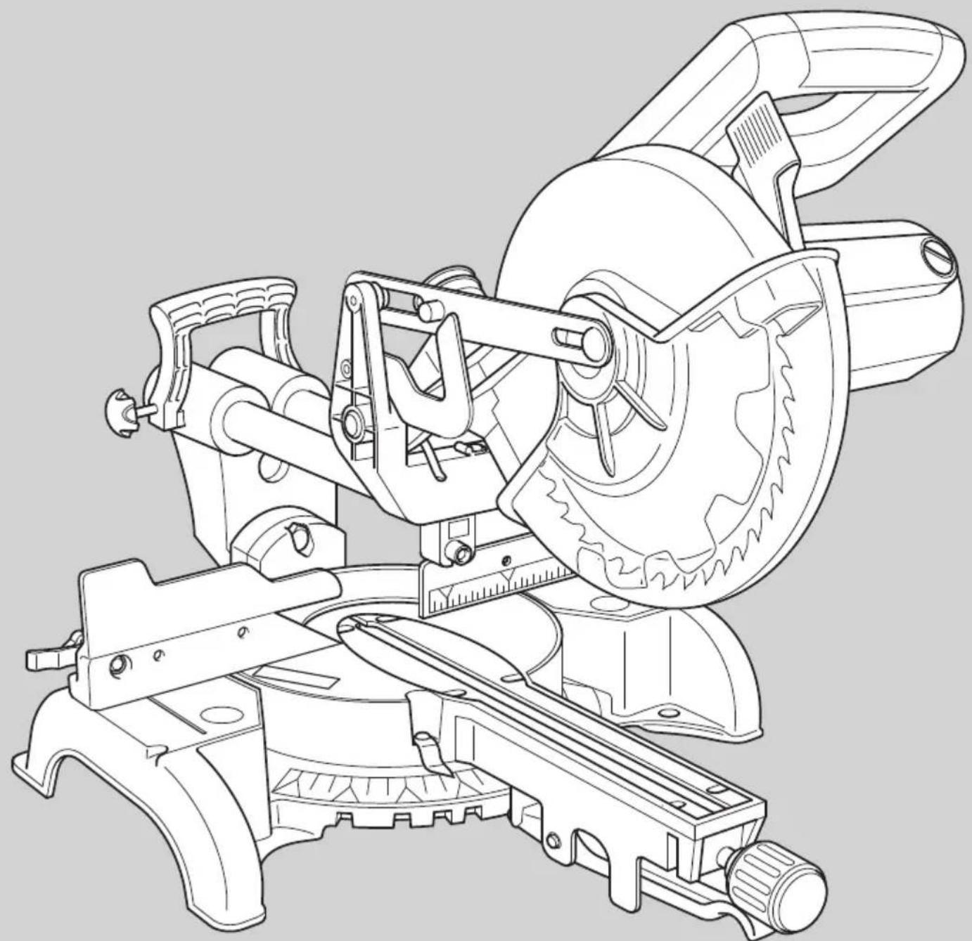
Features
- Laser on/off switch
- Main operating handle
- Motor housing
- Moveable lower guard
- Bench mounting holes
- Kerf plate
- Mitre lock knob
- Mitre detent lever
- Mitre position pointer
- Mitre scale
- Table
12.Left-hand fence - Laser
- Carriage locking knob
- Rear carry handle
- Carriage
- Saw dust outlet
- Metal upper guard
- Removable brush cap
- Bevel scale
- Bevel scale pointer
- Bevel lock handle
- Right-hand fence
- Saw blade
- On/off switch
- Saw arm release lever
Fig Q to S
- Spindle lock
- Left-hand high sliding fence
- High sliding fence clamp
- Work piece clamp
Assembly
Warning! Before assembly, make sure that the tool is switched off and unplugged.
Note: This tool is accurately adjusted before shipping from the factory. Check the following accuracy and readjust them if necessary in order to obtain the best results in operation.
Laser beam
The laser beam alignment is set at manufacturing source and is not user adjustable.
Mitre angle adjustment (fig. B)
The sliding compound litre saw scale can be easily read showing litre angles from 0^ to 45^ to the left and the right. The most common angle cut setting slots have positive stops, permitting fast adjustments to the required position. Follow the process below for the quickest and most accurate adjustments.
Mitre lock knob (fig. B)
The litre lock knob (7) allows the saw to be set to specific angles other than the preset angles of 0^ , 15^ , 22.5^ , 31.6^ , and 45^ , which are set using the litre detent lever (8).
Adjusting the bevel stops at 90^ and 45^ (fig. C - E)
Loosen the bevel lock handle (22) and move the cutting head all the way to the right and tighten the bevel lock handle.
- Use a square to set the blade at 90^ to the table (fig. D).
If an adjustment is necessary, loosen the lock nut (29) and adjust the bolt (28) with the wrench so that the blade is 90^ to the table.
Tighten the lock nut (29).
Align the bevel indicator (21) with the 0^ mark by adjusting the screw (27).
When adjusting the 45^ stop, make sure that the left-hand high sliding fence (42) is adjusted so that the cutting head can be moved to the 45^ position (fig.P).
Release the high sliding fence clamp (43) and move the high fence (42) away from the blade.
- Tighten the high sliding fence clamp (43).
Follow the same procedures for the 90^ but move the cutting head to the left and use the lock nut (31) and adjustment bolt (30).
Adjusting the fence (fig. F - G)
Lower the cutting head and push in the carriage lock pin (34). Make sure that the table is in 0^ litre position.
Place a combination square against the fence (12) and next to the saw blade (24) (fig. F).
If the blade does not contact the square along it's length, loosen the two screws (33) (fig. G) and adjust the fence.
- Tighten the two screws (33).
Bench mounting (fig. H)
Note: We highly recommend that you bolt this metre saw securely to a work bench to gain the maximum stability of your machine. Make sure that the machine is fixed to a bench whenever possible.
- Locate and mark the four bolt holes on the bench.
Drill the bench with an 10mm drill bit. - Bolt the litre saw onto the bench with bolts, washers and nuts.
Note: These fasteners are not supplied with the tool.
Use
Place your hands no closer that 150mm from the blade.
- Hold the workpiece tightly to the table and the fence when cutting. Keep your hands in position until the switch has been released and the blade has completely stopped.
Always make dry runs (without power) before finish cuts so that you can check the path of the blade.
Do not cross your hands.
- Keep both feet firmly on the floor and maintain proper balance.
As you move the saw arm left and right, follow it and stand slightly to the side of the saw blade.
Sight through the guard louvres when following a pencil line.
Basic pullover litre saw operations
Always use the work piece clamp (44) to hold the work piece firmly. Two holes (32) are provided for the clamp (fig. G).
Warning! Make sure that the workpiece is securely held in place with the clamp before operation. Severe personal injury can occur if the workpiece is not secured.
Always position the work piece against the fence. Any piece that is bowed or warped and cannot be held flat on the table or against fence may trap the blade and should not be used.
Pullover cut (fig. I & J)
Warning! Never pull the cutting head assembly and rotating blade toward you during the cut. The blade may try to climb up on the top of the workpiece, causing the cutting head assembly and spinning blade to kick back. Never lower the rotating saw blade down before pulling the cutting head to the front of the saw.
Unlock the carriage (16) with the lock knob (14) and allow the cutting head assembly to move freely.
Move the cutting head to the required litre angle and bevel angle in accordance with the litre cut and bevel cut procedures.
ENGLISH
Hold the main operating handle (2) and pull the carriage (16) forward until the centre of the saw blade is over the front of the work piece.
Operate the on/off switch (25) and press the saw arm release lever (26) to lower the cutting head.
When the saw reaches full speed, push the main operating handle (2) down slowly, cutting through the leading edge of the workpiece.
Slowly move the main operating handle (2) toward the fence to complete the cut.
Release the on/off switch (25) and allow the blade to stop before allowing the cutting head to rise.
Chop cut
Slide the cutting head to the rear position as far as it will go, and lock the carriage (16) with the lock knob (14).
Operate the on/off switch (25) and press the saw arm release lever (26) to lower the cutting head.
- When the saw reaches full speed, push the main operating handle (2) down slowly, cutting through the workpiece.
Release the on/off switch (25) and allow the blade to stop before allowing the cutting head to rise.
Mitre cut
Switch the laser on/off switch (1) to on.
Loosen the litre lock knob (7) and move the table to the required angle. There are preset stops at 0^ , 15^ , 22.5^ , 31.6^ , and 45^ . Tighten the litre lock knob (7).
For any other angle use the metre lock knob (fig. B) to set the metre to the required angle.
Operate the on/off switch (25), then press the saw arm release lever (26) and lower the cutting head.
Release the on/off switch (25) and allow the blade to stop before allowing the cutting head to rise.
Operating the high sliding fence for all bevel and compound metre cuts
- The moveable part of the left side of the fence can be adjusted to provide maximum support of the work piece near the blade, while allowing the saw to bevel to a full 47^ left. The sliding distance is limited by stops in both directions.
Adjusting the fence (fig. R)
Loosen the high sliding fence clamp (43) and slide the fence to the left.
Make a dry run with the saw switched off and check for clearance.
Adjust the fence to be as close to the blade as practical to provide maximum work piece support, without interfering with the up and down movement of the arm.
Tighten the high sliding fence clamp (43) to secure the fence in place.
Warning! The guide groove can become clogged with sawdust. Use a stick or low pressure air to clear the guide groove.
Bevelcut
Make sure that the high sliding fence is adjusted to the correct orientation before adjusting the bevel angle.
Loosen the bevel lock handle (22) (fig. E) and move the cutting head to the required angle. Tighten the bevel lock handle (22).
Operate the on/off switch (25), then press the saw arm release lever (26) and lower the cutting head.
Make sure that the arm is securely locked when bevelling.
Release the on/off switch (25) and allow the blade to stop before allowing the cutting head to rise.
Compound cut
Make sure that the high sliding fence is adjusted to the correct orientation before adjusting the bevel angle to make a compound cut.
A compound cut is a combination of litre cut and bevel cut.
Switch the laser on/off switch (1) to on.
Refer to the above procedures to perform this cut.
Release the on/off switch (25) and allow the blade to stop before allowing the cutting head to rise.
Base moulding cut
Base moulding can be cut vertical against the fence or flat on the table.
Refer to the following table:
| Settings Vertical | Vertical position (back of moulding is against the fence) | Horizontal position (Back of moulding is flat on the table) | |||
| Bevel angle 0° | 45° | ||||
| Moulding position | Left side Right side | Left side | Right side | ||
| Inside corner | Mitre angle | Left at 45° | Right at 45° | 0° 0° | |
| Moulding position | Bottom against table | Bottom against table | Top against fence | Bottom against fence | |
| Finished side | Keep left side of cut | Keep right side of cut | Keep left side of cut | Keep left side of cut | |
| Settings Vertical position (back of moulding is against the fence) | Horizontal position (Back of moulding is flat on the table) | ||||
| Bevel angle 0° | 45° | ||||
| Outside corner | Mitre angle | Right at 45° | Left at 45° | 0° | 0° |
| Moulding position | Bottom against table | Bottom against table | Top against fence | Bottom against fence | |
| Finished side | Keep left side of cut | Keep right side of cut | Keep right side of cut | Keep right side of cut | |
Crown moulding cut
Crown moulding can only be cut flat on the table with this litre saw.
This litre saw has special litre stops on 31.6^ left and right and a bevel indication at 33.9^ for special crown moulding, i.e. 52^ between the back of the moulding and the top flat surface that fits against the ceiling; 38^ between the back of the moulding and the bottom flat surface that fits against the wall.
Refer to the following table to make this crown moulding cut:
| Settings Left side Right side | |||
| Inside corner | Mitre angle | Right 31.6° 31.6° left | |
| Bevel angle | 33.9° 33.9° | ||
| Moulding position | Top against fence Bottom against fence | ||
| Finished side | Keep left side of cut Keep left side of cut | ||
| Outside corner | Mitre angle | Right 31.6° left 31.6° | |
| Bevel angle | 33.9° 33.9° | ||
| Moulding position | Bottom against fence Top against fence | ||
| Finished side | Keep right side of cut Keep right side of cut | ||
Note: . These special stops can not be used with 45^ crown moulding.
Note: Since most rooms do not have angles of exactly 90^ , fine tuning is needed, always make a test cut to confirm the correct angles.
Setting the cutting depth (fig. L)
The depth of cut can be preset for even and repetitive shallow cuts.
Adjust the cutting head down until the teeth of the blade are at the required depth of cut.
While holding the upper arm in position, turn the stop knob (35) until it touches the stop plate (36).
Check the blade depth by moving the cutting head front to back through the full motion of a typical cut along the control arm.
Carrying the tool (fig. M)
Loosen the litre lock knob (7) and turn the table all the way to the right. Lock the table at the 45^ litre angle.
Pull the cutting head to the front of the saw and lock the carriage with the lock knob (14).
Lower the cutting head and push in the lock pin (34) (fig. G).
- Carry the metre saw with the main operating handle (2) and the rear carrying handle (15).
Blade and tooth type
Your litre saw has been supplied with a negative rake saw blade. It is advisable to use a negative rake blade when replacing your saw blade.
| Material Tooth type 600~ | 100T 24~100T | ||
| TCG | ATB | ||
| Wood | Lumber | ● | ● |
| Plywood | ● | ● | |
| Hardboard | ● | ● | |
| Chipboard | ● | ● | |
| Plastic | PVC | ● | |
| ABS | ● | ||
| Acrylic | ● | ||
| PC | ● | ||
| PS | ● | ||
| Non-ferrous metal | Aluminium | ● | |
| Copper | ● | ||
TCG type - For cutting aluminium sheets, tubing extrusions and other non-ferrous metals such as copper, brass. When cutting non-ferrous metals, a negative rake saw blade should be used.
ATB type - For general cutting and trimming of wood, plywood, and sizing pressboard, hardboard, and particle board, when a neat cut is needed.
Changing blades (fig. N - P)
Warning! To avoid injury from accidental starting, always remove the power plug from the power source before
ENGLISH
changing the blades. Use correctly sharpened saw blades. Observe the maximum speed and tooth type marked on the saw blade. Only use Black & Decker recommended blades. To replace the blade (24), proceed as follows:
Using a screwdriver, loosen but do not remove the screw (37). Do not remove the screw completely as it will make re-assembly difficult.
Using a screwdriver, loosen but do not remove the screw (38). Do not remove the screw completely as it will make re-assembly difficult.
Press the saw arm release lever (26) and rotate the moveable lower guard (4) counter clockwise and clear of the blade. Use one hand to hold the guard in place (fig. O).
Move the spindle guard plate (40) counter clockwise (fig. O) to give you access to the spindle bolt (39) that attaches the blade to the metre saw.
Press the spindle lock button (41) which is located on the motor housing to lock the saw blade and prevent it from rotating.
Using the supplied blade spanner, turn the spindle bolt (39) in a clockwise direction to remove the bolt and the blade (24).
Fit a replacement blade, make sure that the teeth are pointing downward and the direction marking on the blade is the same as that on the litre saws guard (clockwise) (fig O).
Loosely fit the spindle bolt (39) by hand and turn counter clockwise.
Press the spindle lock button (41) which is located on the motor housing to lock the saw blade and prevent it from rotating.
Use the blade spanner to tighten the spindle bolt (39) until the blade is secure.
- Allow the moveable lower guard (4) to return to its original position covering the blade.
Move the spindle guard plate (40) into its original position and tighten the two screws (37 and 38).
Warning! Never press the spindle lock while the blade is rotating. Be sure to hold the guard bracket down and firmly tighten the guard bracket screw after installing the blade.
Warning! The guard bracket must be returned to its original position and the screw tightened before activating the saw. Failure to do so may allow the guard to contact the spinning saw blade resulting in damage to the saw and severe personal injury.
Accessories
The performance of your tool depends on the accessory used. Black & Decker and Piranha accessories are engineered to high quality standards and designed to enhance the performance of your tool. By using these accessories you will get the very best from your tool.
Warning! Do not carry the machine by the guard.
Maintenance
Your tool has been designed to operate over a long period of time with a minimum of maintenance. Continuous satisfactory operation depends upon proper tool care and regular cleaning. Regularly clean the ventilation slots with a clean, dry paint brush. To clean the tool, use only mild soap and a damp cloth. Never let any liquid get inside the tool and never immerse any part of the tool into liquid.
Warning! To reduce the risk of injury, turn the unit off and disconnect the tool from the power source before installing and removing accessories, before adjusting or changing setups or when making repairs. Be sure the trigger switch is in the OFF position. An accidental start-up can cause injury.
Mains plug replacement (U.K. & Ireland only)
If a new mains plug needs to be fitted:
- Safely dispose of the old plug.
Connect the brown lead to the live terminal in the new plug.
Connect the blue lead to the neutral terminal.
Warning! No connection is to be made to the earth terminal. Follow the fitting instructions supplied with good quality plugs. Recommended fuse: 13 A.
Protecting the environment

Separate collection. This product must not be disposed of with normal household waste.
Should you find one day that your Black & Decker product needs replacement, or if it is of no further use to you, do not dispose of it with household waste. Make this product available for separate collection.

Separate collection of used products and packaging allows materials to be recycled and used again. Reuse of recycled materials helps prevent environmental pollution and reduces the demand for raw materials.
Local regulations may provide for separate collection of electrical products from the household, at municipal waste sites or by the retailer when you purchase a new product.
Black & Decker provides a facility for the collection and recycling of Black & Decker products once they have reached the end of their working life. To take advantage of this service please return your product to any authorised repair agent who will collect them on our behalf.
You can check the location of your nearest authorised repair agent by contacting your local Black & Decker office at the address indicated in this manual. Alternatively, a list of authorised Black & Decker repair agents and full details of our after-sales service and contacts are available on the Internet at: www.2helpU.com.
Cutting capacities
Max cross cut x depth of cut 62 mm x 305 mm
Max bevel 45^30mm× 305mm
Max litre 45^62mm× 212mm
Max capacity at 33.9^× 31.6^ 45 mm x 254 mm
compound
Technical data
| SMS216 TYPE 1 | |
| Voltage Vac 230 | |
| Power input W 1500 | |
| No-load speed | min 4800 |
| Blade diameter mm 216 | |
| Blade bore mm 30 | |
| Blade body thickness mm 1.8 | |
| max cross-cut capacity 90° mm 305 | |
| max litre capacity 45° mm 212 | |
| max depth of cut 90° mm 62 | |
| max depth of bevel cross-cut mm 30 | |
| Mitre (max positions) left 47° | |
| right 47° | |
| Bevel (max positions) | left 47° |
| right 0° | |
| Weight | kg 13.5 |
Level of sound pressure according to EN61029: Sound pressure (LpA) 98 dB(A), uncertainty (K) 3 dB(A) Sound power (LWA) 111 dB(A), uncertainty (K) 3 dB(A)
Vibration total values (triax vector sum) according to EN61029:
Vibration emission value (a_h) 3.32 m/s², uncertainty (K) 1.5 m/s²
EC declaration of conformity MACHINERY DIRECTIVE

SMS216
Black & Decker declares that these products described under "technical data" are in compliance with: 98/37/EC (until Dec. 28, 2009), 2006/42/EC (from Dec. 29, 2009), EN61029-1, EN61029-2-9
For more information, please contact Black & Decker at the following address or refer to the back of the manual.
The undersigned is responsible for compilation of the technical file and makes this declaration on behalf of Black & Decker.

Kevin Hewitt
Vice-President Global Engineering
Black & Decker Europe, 210 Bath Road, Slough, Berkshire, SL1 3YD
United Kingdom
07-10-2009
Guarantee
Black & Decker is confident of the quality of its products and offers an outstanding guarantee. This guarantee statement is in addition to and in no way prejudices your statutory rights. The guarantee is valid within the territories of the Member States of the European Union and the European Free Trade Area.
If a Black & Decker product becomes defective due to faulty materials, workmanship or lack of conformity, within 24 months from the date of purchase, Black & Decker guarantees to replace defective parts, repair products subjected to fair wear and tear or replace such products to make sure of the minimum inconvenience to the customer unless:
The product has been used for trade, professional or hire purposes.
The product has been subjected to misuse or neglect.
The product has sustained damage through foreign objects, substances or accidents.
Repairs have been attempted by persons other than authorised repair agents or Black & Decker service staff.
ENGLISH
To claim on the guarantee, you will need to submit proof of purchase to the seller or an authorised repair agent. You can check the location of your nearest authorised repair agent by contacting your local Black & Decker office at the address indicated in this manual. Alternatively, a list of authorised Black & Decker repair agents and full details of our after-sales service and contacts are available on the Internet at: www.2helpU.com
Please visit our website www.blackanddecker.co.uk to register your new Black & Decker product and to be kept up to date on new products and special offers. Further information on the Black & Decker brand and our range of products is available at www.blackanddecker.co.uk.
Vice-President Global Engineering
Black & Decker Europe, 210 Bath Road, Slough,
Berkshire, SL1 3YD
Großbritannien
07.10.2009
Garantie
Vice-President Global Engineering
Black & Decker Europe, 210 Bath Road, Slough,
Berkshire, SL1 3YD
Royaume-Uni
07-10-2009
Garantie
Kevin Hewitt
Vice-President Global Engineering
Black & Decker Europe, 210 Bath Road, Slough, Berkshire, SL1 3YD
Regno Unito
07-10-2009
Garanzia
Vice-President Global Engineering
Black & Decker Europe, 210 Bath Road, Slough,
Berkshire, SL1 3YD
Verenigd Koninkrijk
07-10-2009
Garantie
Vice-President Global Engineering
Black & Decker Europe, 210 Bath Road, Slough,
Berkshire, SL1 3YD
Reino Unido
07-10-2009
Garantía
| Regulações Lado esquerdo Lado direito | ||||
| Canto interior | Ânguloda esquadria | Direita a 31.6° Esquerda a 31.6° | ||
| Ângulode bisel | 33.9° 33.9° | |||
| Posão da sanca | Parte superior contra o batente | Parte inferior contra o batente | ||
| Lado(PC)(PC)(PC)PC(PC)PC(PC)PC(PC)PC(PC)PC(PC)PC(PC)PC(PC)PC(PC)PC(PC)PC(PC)PC(PC)PC(PC)PC(PC)PC(PC)PC(PC)PC(PC)PC(PC)PC(PC)PC(PC)PC(PC)PC(PC)PC(PC)PC(PC)PC(PC)PC(PC)PC(PC)PC(PC)PC(PC)PC(PC)PC(PC)PC(PC)PC(PC)PC(PC)PC)PC(PC)PC(PC)PC(PC)PC(PC)PC(PC)PC(PC)PC(PC)PC(PC)PC(PC)PC(PC)PC(PC)PC(PC)PC(PC)PC(PC)PC(PC)PC(PC)PC(PC)PC(PC)PC(PC)PC(PC)PC(PC)PC(PC)PC(PC)PC(PC)PC(PC)PC(PC)PC(PC)PC(PC)PC(PC)PC(PC)PC(PC)PC(PC)PC(PC) Aragalude(PC)PC(PC)PC(PC)PC(PC)PC(PC)PC(PC)PC(PC)PC(PC)PC(PC)PC(PC)PC(PC)PC(PC)PC(PC)PC(PC)PC(PC)PC(PC)PC(PC)PC(PC)PC(PC)PC(PC)PC(PC)PC(PC)PC(PC)PC(PC)PC(PC)PC(PC)PC(PC)PC(PC)PC(PC)PC(PC)PC(PC)PC(PC)PC(PC)PC)(PC)PC(PC)PC(PC)PC(PC)PC(PC)PC(PC)PC(PC)PC(PC)PC(PC)PC(PC)PC(PC)PC(PC)PC(PC)PC(PC)PC(PC)PC(PC)PC(PC)PC(PC)PC(PC)PC(PC)PC(PC)PC(PC)PC(PC)PC(PC)PC(PC)PC(PC)PC(PC)PC(PC)PC(PC)PC(PC)PC(PC)PC(PC)PC(PC)PC)Pace of lado direito do corte | 33.9° 33.9° | |||
| Posão da sanca | Parte inferior contra o batente | Parte inferior contra o batente | ||
| Lado(PC)PC(PC)PC(PC)PC(PC)PC(PC)PC(PC)PC(PC)PC(PC)PC(PC)PC(PC)PC(PC)PC(PC)PC(PC)PC(PC)PC(PC)PC(PC)PC(PC)PC(PC)PC(PC)PC(PC)PC(PC)PC(PC)PC(PC)PC(PC)PC(PC)PC(PC)PC(PC)PC(PC)PC(PC)PC(PC)PC(PC)PC(PC)PC(PC)PC(P)PC(PC)PC(PC)PC(PC)PC(PC)PC(PC)PC(PC)PC(PC)PC(PC)PC(PC)PC(PC)PC(PC)PC(PC)PC(PC)PC(PC)PC(PC)PC(PC)PC(PC)PC(PC)PC(PC)PC(PC)PC(PC)PC(PC)PC(PC)PC(PC)PC(PC)PC(PC)PC(PC)PC(PC)PC(PC)PC(PC)PC(PC)PC(PC)PC(PC)(PC)PC(PC)(PC)PC(PC)(PC)PC(PC)(PC)PC(PC)(PC)PC(PC)(PC)PC(PC)(PC)PC(PC)(PC)PC(PC)(PC)PC(PC)(PC)PC(PC)(PC)PC(PC)(PC)PC(PC)(PC)PC(PC)(PC)PC(PC)(PC)PC(PC)(PC)PC(PC)(PC)PC(PC)(PC)PC(PC)(PC)PC(PC)(PC)PC(PC)(P)PC(PC)(P)PC(PC)(P)PC(PC)(P)PC(PC)(P)PC(PC)(P)PC(PC)(P)PC(PC)(P)PC(PC)(P)PC(PC)(P)PC(PC)(P)PC(PC)(P)PC(PC)(P)PC(PC)(P)PC(PC)(P)PC(PC)(P)PC(PC)(P)PC(PC)(P)PC(PC)(P)PC(PC)(P)PC(PC)(PC)PC(PC)(P)PC(PC)(P)PC(PC)(P)PC(PC)(P)PC(PC)(P)PC(PC)(P)PC(PC)(P)PC(PC)(P)PC(PC)(P)PC(PC)(P)PC(PC)(P)PC(PC)(P)PC(PC)(P)PC(PC)(P)PC(PC)(P)PC(PC)(P)PC(PC)(P)PC(PC)(P)PC(PC)(PC)PC(PC)(PC)PC(PC)(P)PC(PC)(P)PC(PC)(P)PC(PC)(P)PC(PC)(P)PC(PC)(P)PC(PC)(P)PC(PC)(P)PC(PC)(P)PC(PC)(P)PC(PC)(P)PC(PC)(P)PC(PC)(P)PC(PC)(P)PC(PC)(P)PC(PC)(P)PC(PC)(P)PC(PC)(PC)PC(PC)(P)PC(PC)(PC)PC(PC)(P)PC(PC)(P)PC(PC)(P)PC(PC)(P)PC(PC)(P)PC(PC)(P)PC(PC)(P)PC(PC)(P)PC(PC)(P)PC(PC)(P)PC(PC)(P)PC(PC)(P)PC(PC)(P)PC(PC)(P)PC(PC)(P)PC(PC)(P)PC(PC)(P)PC(PC)(PC)PC(PC)(PC)PC(PC)(PC)PC(PC)(P)PC(PC)(P)PC(PC)(P)PC(PC)(P)PC(PC)(P)PC(PC)(P)PC(PC)(P)PC(PC)(P)PC(PC)(P)PC(PC)(P)PC(PC)(P)PC(PC)(P)PC(PC)(P)PC(PC)(P)PC(PC)(P)PC(PC)(P)PC(PC)(PC)PC(PC)(P)PC(PC)(P)PC(PC)(PC)PC(PC)(P)PC(PC)(P)PC(PC)(P)PC(PC)(P)PC(PC)(P)PC(PC)(P)PC(PC)(P)PC(PC)(P)PC(PC)(P)PC(PC)(P)PC(PC)(P)PC(PC)(P)PC(PC)(P)PC(PC)(P)PC(PC)(P)PC(PC)(P)PC(PC)(PC)PC(PC)(P)PC(PC)(PC)PC(PC)(PC)PC(PC)(P)PC(PC)(P)PC(PC)(P)PC(PC)(P)PC(PC)(P)PC(PC)(P)PC(PC)(P)PC(PC)(P)PC(PC)(P)PC(PC)(P)PC(PC)(P)PC(PC)(P)PC(PC)(P)PC(PC)(P)PC(PC)(P)PC(PC)(P)PC(PC)(PC)PC(PC)(PC)PC(PC)(P)PC(PC)(PC)PC(PC)(P)PC(PC)(P)PC(PC)(P)PC(PC)(P)PC(PC)(P)PC(PC)(P)PC(PC)(P)PC(PC)(P)PC(PC)(P)PC(PC)(P)PC(PC)(P)PC(PC)(P)PC(PC)(P)PC(PC)(P)PC(PC)(P)PC(PC)(P)PC(PC)(PC)PC(PC)(PC)PC(PC)(PC)PC(PC)(PC)PC(PC)(P)PC(PC)(P)PC(PC)(P)PC(PC)(P)PC(PC)(P)PC(PC)(P)PC(PC)(P)PC(PC)(P)PC(PC)(P)PC(PC)(P)PC(PC)(P)PC(PC)(P)PC(PC)(P)PC(PC)(P)PC(PC)(P)PC(PC)(PC)PC(PC)(P)PC(PC)(P)PC(PC)(P)PC(PC)(PC)PC(PC)(P)PC(PC)(P)PC(PC)(P)PC(PC)(P)PC(PC)(P)PC(PC)(P)PC(PC)(P)PC(PC)(P)PC(PC)(P)PC(PC)(P)PC(PC)(P)PC(PC)(P)PC(PC)(P)PC(PC)(P)PC(PC)(P)PC(PC)(PC)PC(PC)(P)PC(PC)(P)PC(PC)(PC)PC(PC)(PC)PC(PC)(P)PC(PC)(P)PC(PC)(P)PC(PC)(P)PC(PC)(P)PC(PC)(P)PC(PC)(P)PC(PC)(P)PC(PC)(P)PC(PC)(P)PC(PC)(P)PC(PC)(P)PC(PC)(P)PC(PC)(P)PC(PC)(P)PC(PC)(PC)PC(PC)(P)PC(PC)(PC)PC(PC)(P)PC(PC)(PC)PC(PC)(P)PC(PC)(P)PC(PC)(P)PC(PC)(P)PC(PC)(P)PC(PC)(P)PC(PC)(P)PC(PC)(P)PC(PC)(P)PC(PC)(P)PC(PC)(P)PC(PC)(P)PC(PC)(P)PC(PC)(P)PC(PC)(P)PC(PC)(PC)PC(PC)(P)PC(PC)(PC)PC(PC)(PC)PC(PC)(PC)PC(PC)(P)PC(PC)(P)PC(PC)(P)PC(PC)(P)PC(PC)(P)PC(PC)(P)PC(PC)(P)PC(PC)(P)PC(PC)(P)PC(PC)(P)PC(PC)(P)PC(PC)(P)PC(PC)(P)PC(PC)(P)PC(PC)(P)PC(PC)(PC)PC(PC)(PC)PC(PC)(P)PC(PC)(P)PC(PC)(PC)PC(PC)(P)PC(PC)(P)PC(PC)(P)PC(PC)(P)PC(PC)(P)PC(PC)(P)PC(PC)(P)PC(PC)(P)PC(PC)(P)PC(PC)(P)PC(PC)(P)PC(PC)(P)PC(PC)(P)PC(PC)(P)PC(PC)(P)PC(PC)(PC)PC(PC)(PC)PC(PC)(P)PC(PC)(PC)PC(PC)(PC)PC(PC)(P)PC(PC)(P)PC(PC)(P)PC(PC)(P)PC(PC)(P)PC(PC)(P)PC(PC)(P)PC(PC)(P)PC(PC)(P)PC(PC)(P)PC(PC)(P)PC(PC)(P)PC(PC)(P)PC(PC)(P)PC(PC)(P)PC(PC)(PC)PC(PC)(PC)PC(PC)(PC)PC(PC)(P)PC(PC)(PC)PC(PC)(P)PC(PC)(P)PC(PC)(P)PC(PC)(P)PC(PC)(P)PC(PC)(P)PC(PC)(P)PC(PC)(P)PC(PC)(P)PC(PC)(P)PC(PC)(P)PC(PC)(P)PC(PC)(P)PC(PC)(P)PC(PC)(P)PC(PC)(PC)PC(PC)(PC)PC(PC)(PC)PC(PC)(PC)PC(PC)(PC)PC(PC)(P)PC(PC)(P)PC(PC)(P)PC(PC)(P)PC(PC)(P)PC(PC)(P)PC(PC)(P)PC(PC)(P)PC(PC)(P)PC(PC)(P)PC(PC)(P)PC(PC)(P)PC(PC)(P)PC(PC)(P)PC(PC)(PC)PC(PC)(P)PC(PC)(P)PC(PC)(P)PC(PC)(P)PC(PC)(PC)PC(PC)(P)PC(PC)(P)PC(PC)(P)PC(PC)(P)PC(PC)(P)PC(PC)(P)PC(PC)(P)PC(PC)(P)PC(PC)(P)PC(PC)(P)PC(PC)(P)PC(PC)(P)PC(PC)(P)PC(PC)(P)PC(PC)(PC)PC(PC)(P)PC(PC)(P)PC(PC)(P)PC(PC)(PC)PC(PC)(PC)PC(PC)(P)PC(PC)(P)PC(PC)(P)PC(PC)(P)PC(PC)(P)PC(PC)(P)PC(PC)(P)PC(PC)(P)PC(PC)(P)PC(PC)(P)PC(PC)(P)PC(PC)(P)PC(PC)(P)PC(PC)(P)PC(PC)(PC)PC(PC)(P)PC(PC)(P)PC(PC)(PC)PC(PC)(P)PC(PC)(PC)PC(PC)(P)PC(PC)(P)PC(PC)(P)PC(PC)(P)PC(PC)(P)PC(PC)(P)PC(PC)(P)PC(PC)(P)PC(PC)(P)PC(PC)(P)PC(PC)(P)PC(PC)(P)PC(PC)(P)PC(PC)(P)PC(PC)(PC)PC(PC)(P)PC(PC)(P)PC(PC)(PC)PC(PC)(PC)PC(PC)(PC)PC(PC)(P)PC(PC)(P)PC(PC)(P)PC(PC)(P)PC(PC)(P)PC(PC)(P)PC(PC)(P)PC(PC)(P)PC(PC)(P)PC(PC)(P)PC(PC)(P)PC(PC)(P)PC(PC)(P)PC(PC)(P)PC(PC)(PC)PC(PC)(P)PC(PC)(PC)PC(PC)(P)PC(PC)(P)PC(PC)(PC)PC(PC)(P)PC(PC)(P)PC(PC)(P)PC(PC)(P)PC(PC)(P)PC(PC)(P)PC(PC)(P)PC(PC)(P)PC(PC)(P)PC(PC)(P)PC(PC)(P)PC(PC)(P)PC(PC)(P)PC(PC)(P)PC(PC)(PC)PC(PC)(P)PC(PC)(PC)PC(PC)(P)PC(PC)(PC)PC(PC)(PC)PC(PC)(P)PC(PC)(P)PC(PC)(P)PC(PC)(P)PC(PC)(P)PC(PC)(P)PC(PC)(P)PC(PC)(P)PC(PC)(P)PC(PC)(P)PC(PC)(P)PC(PC)(P)PC(PC)(P)PC(PC)(P)PC(PC)(PC)PC(PC)(P)PC(PC)(PC)PC(PC)(PC)PC(PC)(P)PC(PC)(PC)PC(PC)(P)PC(PC)(P)PC(PC)(P)PC(PC)(P)PC(PC)(P)PC(PC)(P)PC(PC)(P)PC(PC)(P)PC(PC)(P)PC(PC)(P)PC(PC)(P)PC(PC)(P)PC(PC)(P)PC(PC)(P)PC(PC)(PC)PC(PC)(P)PC(PC)(PC)PC(PC)(PC)PC(PC)(PC)PC(PC)(PC)PC(PC)(P)PC(PC)(P)PC(PC)(P)PC(PC)(P)PC(PC)(P)PC(PC)(P)PC(PC)(P)PC(PC)(P)PC(PC)(P)PC(PC)(P)PC(PC)(P)PC(PC)(P)PC(PC)(P)PC(PC)(P)PC(PC)(PC)PC(PC)(PC)PC(PC)(P)PC(PC)(P)PC(PC)(P)PC(PC)(PC)PC(PC)(P)PC(PC)(P)PC(PC)(P)PC(PC)(P)PC(PC)(P)PC(PC)(P)PC(PC)(P)PC(PC)(P)PC(PC)(P)PC(PC)(P)PC(PC)(P)PC(PC)(P)PC(PC)(P)PC(PC)(P)PC(PC)(PC)PC(PC)(PC)PC(PC)(P)PC(PC)(P)PC(PC)(PC)PC(PC)(PC)PC(PC)(P)PC(PC)(P)PC(PC)(P)PC(PC)(P)PC(PC)(P)PC(PC)(P)PC(PC)(P)PC(PC)(P)PC(PC)(P)PC(PC)(P)PC(PC)(P)PC(PC)(P)PC(PC)(P)PC(PC)(P)PC(PC)(PC)PC(PC)(PC)PC(PC)(P)PC(PC)(PC)PC(PC)(P)PC(PC)(PC)PC(PC)(P)PC(PC)(P)PC(PC)(P)PC(PC)(P)PC(PC)(P)PC(PC)(P)PC(PC)(P)PC(PC)(P)PC(PC)(P)PC(PC)(P)PC(PC)(P)PC(PC)(P)PC(PC)(P)PC(PC)(P)PC(PC)(O) (2020) (2020) (2020) (2020) (2020) (2020) (2020) (2020) (2020) (2020) (2020) (2020) (2020) (2020) (2020) (2020) (2020) (2) (2020) (2020) (2020) (2020) (2020) (2020) (2020) (2020) (2020) (2020) (2020) (2020) (2020) (2020) (2020) (2020) (2). | ||||
Vice-President Global Engineering
Black & Decker Europe, 210 Bath Road, Slough, Berkshire, SL1 3YD
Reino Unido
07-10-2009
Garantia
Andre former for risiko
Stille inn skjaeredybden (figur L)
Vice-President Global Engineering
Black & Decker Europe, 210 Bath Road, Slough,
Berkshire, SL1 3YD
Storbritannia
07.10.2009
Garanti
Black & Decker er trygg på kvaliteten på sineprodukter og tilbyr en enestående garanti. Denne garantierklæringenkommen i tillegg til dine lovbestemterettigheter og er ikke i konflikt medppe. Garantien er gyldig i EU- og EFTA-medlemsstatene.
Vice-President Global Engineering
Black & Decker Europe, 210 Bath Road, Slough,
Berkshire, SL1 3YD
Storbritannien
07-10-2009
Garanti
Vice-President Global Engineering
Black & Decker Europe, 210 Bath Road, Slough,
Berkshire, SL1 3YD
Tutoc biokou kai dovtiwv
To paaltoonpiiovocac evai eonlaouevoe bioko apvtiknc ywiac kottc. suviotatai va xpoipoinoe tbiokopvtikncywiac kottc, otavavtikaiotate to bioko tou pioviouac.
Do not forget to register your product! www.blackanddecker.co.uk/productregistration
Register your product online at www.blackanddecker.co.uk/productregistration or send your name, surname and product code to Black & Decker in your country.