USER MANUAL BES701 BLACK & DECKER
natural_image
Technical line drawing of a mechanical power saw assembly (no text or symbols)
English (original instructions) 6

natural_image
Technical line drawing of a mechanical assembly with labeled component (22), no readable text or symbols beyond the number and letter marker.

natural_image
Technical line drawing of a mechanical assembly with numbered component (31), no readable text or symbols present
natural_image
Technical line drawing of a mechanical assembly with hands operating a lathe machine (no text or symbols visible)
natural_image
Technical illustration of hands operating a mechanical assembly with spring and motor components (no text or symbols visible)
natural_image
Technical illustration of a mechanical assembly with a hand operating a tool (no visible text or symbols)
natural_image
Mechanical assembly diagram showing a hand operating a motor with no visible text or symbols
natural_image
Technical line drawing of a mechanical assembly with gears and springs (no text or symbols)
natural_image
Line drawing of a 3D cube with visible grain patterns inside, labeled 'P' in the corner (no text or symbols on the diagram itself)
natural_image
Technical line drawing of a mechanical assembly with a hand operating a base (no text or symbols present)
natural_image
Line drawing of a hand inserting a component into a device (no text or symbols visible)
natural_image
Technical diagram of a mechanical device with no visible text or symbols, featuring a circular background and no readable labels.
natural_image
Technical line drawing of a mechanical device with multiple blades and central shaft (no text or symbols)
Intended use
Your BLACK+DECKER BES701 sliding compound mitre saw has been designed for sawing wood, plastic and nonferrous metal only. This tool is intended for non professional users.
Safety instructions
Warning! Read all safety warnings, instructions, illustrations and specifications
provided with power tool. Failure to follow all instructions listed below may result in electric shock, fire and/or serious injury.
Save all warnings and instructions for future reference. The term "power tool" in the warnings listed below refers to your mains operated (corded) power tool or battery operated (cordless) power tool.
- Work area safety
a. Keep work area clean and well lit. Cluttered or dark areas invite accidents.
b. Do not operate power tools in explosive atmospheres, such as in the presence of flammable liquids, gases or dust. Power tools create sparks which may ignite the dust or fumes.
c. Keep children and bystanders away while operating a power tool. Distractions can cause you to lose control.
- Electrical safety
a. Power tool plugs must match the outlet. Never modify the plug in any way. Do not use any adapter plugs with earthed (grounded) power tools. Unmodified plugs and matching outlets will reduce risk of electric shock.
b. Avoid body contact with earthed or grounded surfaces such as pipes, radiators, ranges and refrigerators. There is an increased risk of electric shock if your body is earthed or grounded.
c. Do not expose power tools to rain or wet conditions.
Water entering a power tool will increase the risk of electric shock.
d. Do not abuse the cord. Never use the cord for carrying, pulling or unplugging the power tool. Keep cord away from heat, oil, sharp edges or moving parts. Damaged or entangled cords increase the risk of electric shock.
e. When operating a power tool outdoors, use an extension cord suitable for outdoor use. Use of a cord suitable for outdoor use reduces the risk of electric shock.
f. If operating a power tool in a damp location is unavoidable, use a residual current device (RCD) protected supply. Use of an RCD reduces the risk of electric shock.
- Personal safety
a. Stay alert, watch what you are doing and use common sense when operating a power tool. Do not use a power tool while you are tired or under the influence of drugs, alcohol or medication. A moment of inattention while operating power tools may result in serious personal injury.
b. Use personal protective equipment. Always wear eye protection. Protective equipment such as a dust mask, non-skid safety shoes, hard hat, or hearing protection used for appropriate conditions will reduce personal injuries.
c. Prevent unintentional starting. Ensure the switch is in the off-position before connecting to power source and/or battery pack, picking up or carrying the tool. Carrying power tools with your finger on the switch or energising power tools that have the switch on invites accidents.
d. Remove any adjusting key or wrench before turning the power tool on. A wrench or a key left attached to a rotating part of the power tool may result in personal injury.
e. Do not overreach. Keep proper footing and balance at all times. This enables better control of the power tool in unexpected situations.
f. Dress properly. Do not wear loose clothing or jewellery. Keep your hair and clothing away from moving parts. Loose clothes, jewellery or long hair can be caught in moving parts.
g. If devices are provided for the connection of dust extraction and collection facilities, ensure these are connected and properly used. Use of dust collection can reduce dust-related hazards.
h. Do not let familiarity gained from frequent use of tools allow you to become complacent and ignore tool safety principles. A careless action can cause severe injury within a fraction of a second.
- Power tool use and care
a. Do not force the power tool. Use the correct power tool for your application. The correct power tool will do the job better and safer at the rate for which it was designed.
b. Do not use the power tool if the switch does not turn it on and off. Any power tool that cannot be controlled with the switch is dangerous and must be repaired.
c. Disconnect the plug from the power source and/or the battery pack from the power tool before making any adjustments, changing accessories, or storing power tools. Such preventive safety measures reduce the risk of starting the power tool accidentally.
d. Store idle power tools out of the reach of children and do not allow persons unfamiliar with the power tool or these instructions to operate the power tool.
Power tools are dangerous in the hands of untrained users.
e. Maintain power tools and accessories. Check for misalignment or binding of moving parts, breakage of parts and any other condition that may affect the power tools operation. If damaged, have the power tool repaired before use. Many accidents are caused by poorly maintained power tools.
f. Keep cutting tools sharp and clean. Properly maintained cutting tools with sharp cutting edges are less likely to bind and are easier to control.
g. Use the power tool, accessories and tool bits etc. in accordance with these instructions, taking into account the working conditions and the work to be performed. Use of the power tool for operations different from those intended could result in a hazardous situation.
h. Keep handles and grasping surfaces dry, clean and free from oil and grease. Slippery handles and greasy surfaces do not allow for safe handling and control of the tool in unexpected situations.
- Service
a. Have your power tool serviced by a qualified repair person using only identical replacement parts. This will ensure that the safety of the power tool is maintained.
Safety instructions for mitre saws
- Mitre saws are intended to cut wood or wood-like products, they cannot be used with abrasive cut-off wheels for cutting ferrous material such as bars, rods, studs, etc. Abrasive dust causes moving parts such as the lower guard to jam.
Sparks from abrasive cutting will burn the lower guard, the kerf insert and other plastic parts.
Use clamps to support the workpiece whenever possible. If supporting the workpiece by hand, you must always keep your hand at least 100 mm from either side of the saw blade. Do not use this saw to cut pieces that are too small to be securely clamped or held by hand. If your hand is placed too close to the saw blade, there is an increased risk of injury from blade contact.
- The workpiece must be stationary and clamped or held against both the fence and the table. Do not feed the workpiece into the blade or cut “freehand” in any way. Unrestrained or moving workpieces could be thrown at high speeds, causing injury.
- Push the saw through the workpiece. Do not pull the saw through the workpiece. To make a cut, raise the saw head and pull it out over the workpiece without cutting, start the motor, press the saw head down and push the saw through the workpiece.
Cutting on the pull stroke is likely to cause the saw blade to climb on top of the workpiece and violently throw the blade assembly towards the operator.
- Never cross your hand over the intended line of cutting either in front or behind the saw blade. Supporting the workpiece “cross handed” i.e. holding the workpiece to the right of the saw blade with your left hand or vice versa is very dangerous.
Do not reach behind the fence with either hand closer than 100 mm from either side of the saw blade, to remove wood scraps, or for any other reason while the blade is spinning. The proximity of the spinning saw blade to your hand may not be obvious and you may be seriously injured.
- Inspect your workpiece before cutting. If the workpiece is bowed or warped, clamp it with the outside bowed face toward the fence. Always make certain that there is no gap between the workpiece, fence and table along the line of the cut. Bent or warped workpieces can twist or shift and may cause binding on the spinning saw blade while cutting. There should be no nails or foreign objects in the workpiece.
Do not use the saw until the table is clear of all tools, wood scraps, etc., except for the workpiece. Small debris or loose pieces of wood or other objects that contact the revolving blade can be thrown with high speed.
- Cut only one workpiece at a time. Stacked multiple workpieces cannot be adequately clamped or braced and may bind on the blade or shift during cutting.
- Ensure the mitre saw is mounted or placed on a level, firm work surface before use. A level and firm work surface reduces the risk of the mitre saw becoming unstable.
- Plan your work. Every time you change the bevel or mitre angle setting, make sure the adjustable fence is set correctly to support the workpiece and will not interfere with the blade or the guarding system. Without turning the tool "ON" and with no workpiece on the table, move the saw blade through a complete simulated cut to assure there will be no interference or danger of cutting the fence.
- Provide adequate support such as table extensions, saw horses, etc. for a workpiece that is wider or longer than the table top. Workpieces longer or wider than the mitre saw table can tip if not securely supported. If the cut-off piece or workpiece tips, it can lift the lower guard or be thrown by the spinning blade.
Do not use another person as a substitute for a table extension or as additional support. Unstable support for the workpiece can cause the blade to bind or the workpiece to shift during the cutting operation pulling you and the helper into the spinning blade.
- The cut-off piece must not be jammed or pressed by any means against the spinning saw blade.
If confined, i.e. using length stops, the cut-off piece could get wedged against the blade and thrown violently.
- Always use a clamp or a fixture designed to properly support round material such as rods or tubing. Rods have a tendency to roll while being cut, causing the blade to "bite" and pull the work with your hand into the blade.
- Let the blade reach full speed before contacting the workpiece. This will reduce the risk of the workpiece being thrown.
If the workpiece or blade becomes jammed, turn the mitre saw off. Wait for all moving parts to stop and disconnect the plug from the power source and/or remove the battery pack. Then work to free the jammed material. Continued sawing with a jammed workpiece could cause loss of control or damage to the mitre saw.
- After finishing the cut, release the switch, hold the saw head down and wait for the blade to stop before removing the cut-off piece. Reaching with your hand near the coasting blade is dangerous.
- Hold the handle firmly when making an incomplete cut or when releasing the switch before the saw head is completely in the down position. The braking action of the saw may cause the saw head to be suddenly pulled downward, causing a risk of injury.
- The intended use is described in this instruction manual. The use of any accessory or attachment or performance of any operation with this tool other than those recommended in this instruction manual may present a risk of personal injury and/or damage to property.
◆ Do not use cracked/bent/damaged/deformed saw blades.
◆ Replace the kerf plate when worn.
Kerf plate replacement
To replace the kerf plates, loosen the screws holding the kerf plates in place. Adjust so that the kerf plates are as close as possible without interfering with the blade's movement.
Do not use blades of larger or smaller diameter than recommended. For the proper blade rating refer to the technical data. Use only the blades specified in this manual, complying with EN 847-1.
◆ Do not use High Speed Steel (HSS) saw blades.

Warning! Contact with or inhalation of dusts from sawing applications may endanger
the health of the operator and possible bystanders. Wear a dust mask specifically designed for protection against dust and fumes and ensure that persons within or entering the work area are also protected.
Cutting accessory contacting a "live" wire may make exposed metal parts of the power tool "live" and could give the operator an electric shock
- Select the correct blade for the material to be cut.
- Do not operate the machine without the guard in position. Do not operate the machine if the guard does not function or is not maintained properly.
- Ensure that the arm is securely fixed when performing bevel cuts.
◆ Before each cut ensure that the machine is stable.
◆ Keep handles dry, clean and free from oil and grease.
- Keep the surrounding area of the machine well maintained and free of loose materials, e.g. chips and off-cuts.
- Ensure the machine and the work area are provided with adequate general or localised lighting.
- Do not allow untrained people to operate this machine.
- Ensure that the blade is mounted correctly before use. Make sure that the blade rotates in the correct direction. Keep the blade sharp. Follow instruction for lubricating and changing accessories.
- Ensure the speed marked on the saw blade is at least equal to the speed marked on the saw.
◆ Ensure that any spacers and spindle rings used are suitable for the purpose as stated by BLACK+DECKER.
◆ Repairs to the cut line guidance system should be carried out by authorised repair agents or BLACK+DECKER service staff.
◆ Unplug the machine before carrying out any maintenance or when changing the blade.
- Never perform any cleaning, maintenance, removal of any off-cuts or other parts of the work piece form the cutting area when the machine is running and the saw head is not in the rest position.
- When possible, always mount the machine to a bench.
◆ Make sure all locking knobs and handles are tight before starting any operation.
◆ Never use your saw without the table insert.
- Never attempt to stop the machine in motion rapidly by jamming a tool or other means against the blade; serious accidents can be caused unintentionally in this way.
- Before using or fitting any accessory consult the instruction manual. The improper use of an accessory can cause damage.
- Raise the blade from the table insert in the work piece prior to releasing the on/of switch.
- Do not wedge anything against the fan to hold the motor shaft.
- The blade guard on your saw will automatically raise when the arm is brought down; it will lower over the blade when the arm is raised. The guard can be raised by hand when installing or removing saw blades or for inspection of the saw. Never raise the blade guard manually unless the machine is switched off.
◆ Check periodically that the motor air slots are clean and free of chips.
- Never make the warning signs on the power tool unrecognisable.
- Never stand on the power tool. Serious injuries could occur when the power tool tips over or when coming in contact with the saw blade.
- Do not take hold of the saw blade after working before it has cooled. The saw blade becomes very hot while working.
- To avoid injury from materials being thrown, unplug the saw to avoid accidental starting, and then remove small materials.
Before use and after any maintenance the blade guard must be checked to ensure proper function. This test must be performed with the saw switched off and unplugged. The arm must be raised and lowered to ensure the guard covers the blade and the blade does not contact the guard. If the guard fails to operate correctly, have your power tool serviced by a qualified repair agent. Call BLACK+DECKER customer services for you nearest service agent.
- This mitre saw has been designed for sawing wood, plastic and nonferrous metal only.
Do not use the saw to cut other materials than those recommended by the manufacturer.
- Do not take hold of the saw blade after working before it has cooled. The saw blade becomes very hot while working.

Warning! Cutting plastics, sap coated wood, and
other materials may cause melted material to accumulate on the blade tips and the body of the saw blade, increasing the risk of the blade overheating and binding while cutting.
Residual risks
The following risks are inherent to the use of saws:
Even with the application of the relevant safety regulations and the implementation of safety devices, certain residual risks can not be avoided. These include:
◆ Injuries caused by touching any rotating/moving parts.
◆ Impairment of hearing.
◆ Risk of accidents caused by the uncovered parts of the rotating saw blade.
ENGLISH
(Original instructions)
◆ Risk of injury when changing any parts, blades or accessories.
◆ Risk of squeezing fingers when opening the guards.
◆ Health hazards caused by breathing dust developed when sawing wood, especially oak, beech and MDF.
◆ Injuries caused by prolonged use of a tool. When using any tool for prolonged periods ensure you take regular breaks.
Noise
The declared noise emission values have been measured in accordance with a standard test method and may be used for comparing one tool with another.
The declared noise emission values may also be used in a preliminary assessment of exposure.
Warning! The noise emissions during actual use of the power tool can differ from the declared values depending on the ways in which the tool is used especially what kind of workpiece is processed.
Warning! Always wear proper personal hearing protection. Under some conditions and duration of use, noise from this product may contribute to hearing loss. Be aware of the following factors influencing exposure to noise:
◆ Use saw blades designed to reduce the emitted noise,
◆ Use only well sharpened saw blades, and
◆ Use specifically designed noise-reduction saw blades.
The following pictograms along with the date code are shown on the tool:

Warning! To reduce the risk of injury, the user must read the instruction manual.

Wear safety glasses or goggles

Wear ear protection

Wear a dust mask

Keep hands away from blade

No Hands Zone - Keep fingers and arms away from rotational saw blades

Wear gloves when handling saw blades

Do not stare at operating lamp

Do not expose to rain.

Disconnect the mains plug if the cord becomes damaged or entangled.
Electrical safety

This tool is double insulated; therefore no earth wire is required. Always check that the power supply corresponds to the voltage on the rating plate.
If the supply cord is damaged, it must be replaced by the manufacturer or an authorised BLACK+DECKER Service Centre in order to avoid a hazard.
Voltage drops
Inrush currents cause short-time voltage drops. Under unfavourable power supply conditions, other equipment may be affected. If the system impedance of the power supply is lower than 0.214 Ω, disturbances are unlikely to occur.
Using an extension cable
Always use an approved extension cable suitable for the power input of this tool (see technical data). Before use, inspect the extension cable for signs of damage, wear and ageing. Replace the extension cable if damaged or defective. When using a cable reel, always unwind the cable completely. Use of an extension cable not suitable for the power input of the tool or which is damaged or defective may result in a risk of fire and electric shock.
Features
This tool includes some or all of the following features.
- Slide bars
- Bevel lock knob
- Clamp lock screw
- Work piece clamp
- Table extension rail
- Bolt holes
- Mitre angle indicator
- Kerf plate
- Mitre lock knob
- Base plate
- Rotary table
- Rear fence
- Saw blade
- Blade guard
- Motor housing
- Saw head locking pin
- Main handle
- Trigger switch
-
Safety release lever
-
Safety guard mounting plate
-
Cut line light on/off button
-
Extension rail locking screw
-
Dust bag
- Adjustable support foot
- Bevel angle indicator
- Mitre angle scale
- Bevel angle scale
- Slide bar locking screw
- Depth of cut screw
- Blade change tool
- Spindle lock
- Mitre lock release
Assembly
Your mitre saw is part assembled in the carton.
◆ Open the box and lift the saw out.
◆ Place the saw on a smooth, flat surface such as a workbench or strong table.
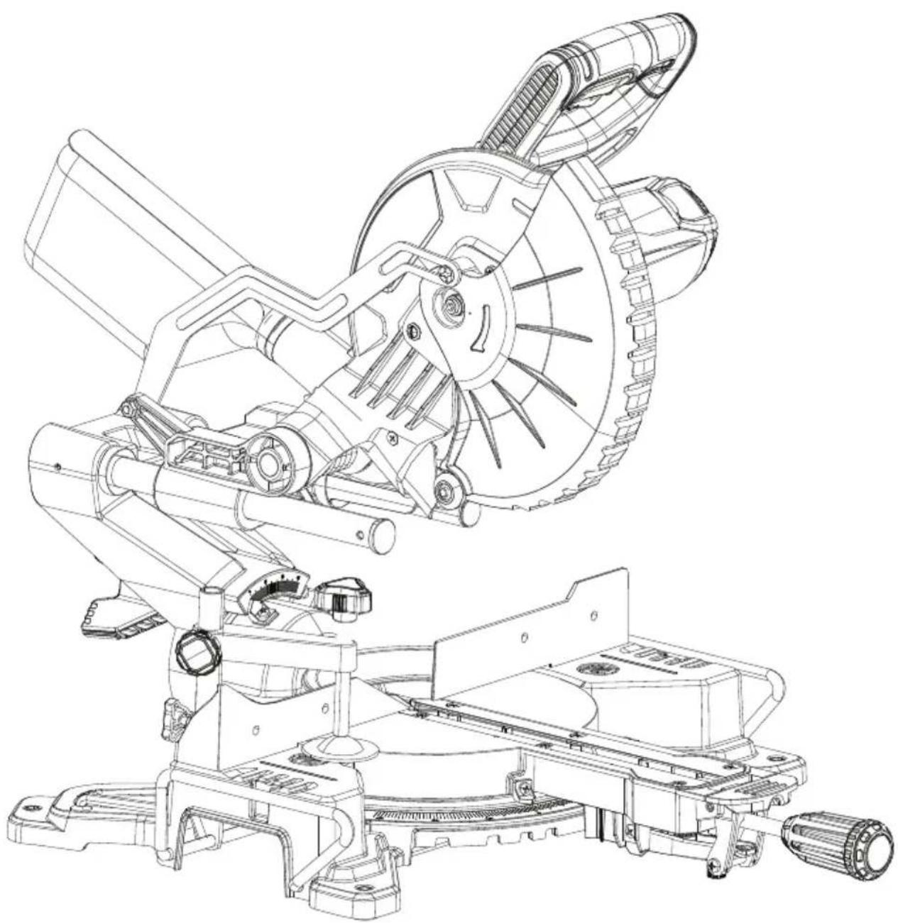
- Examine Assembly diagram on page 2 of this manual to become familiar with the saw and its various parts. The section on adjustments will refer to these terms and you must know what and where the parts are.
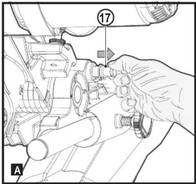
- When the tool is shipped, the head is locked in the lowered position by the saw head locking pin (17). Pull the saw head locking pin (17) as shown in figure A.
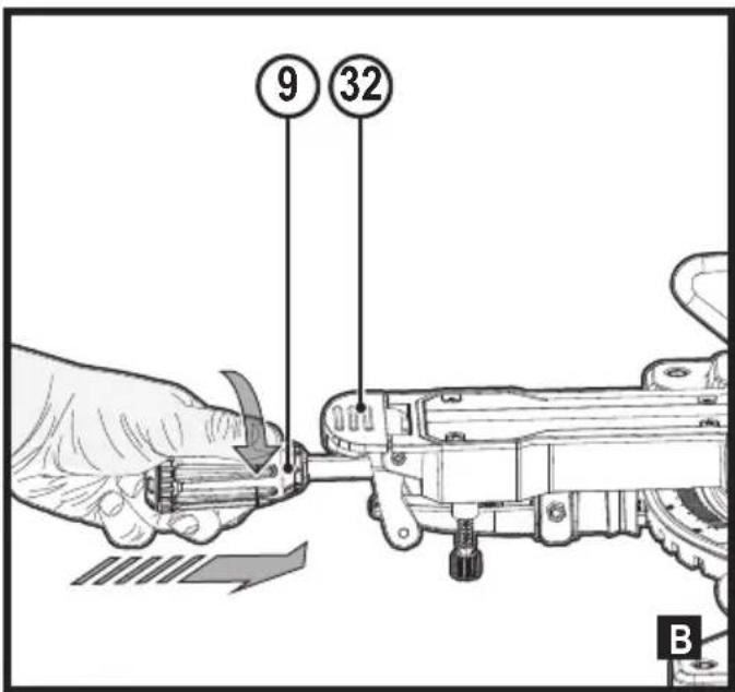
- The mitre locking knob (9) is not assembled for shipping. Remove the mitre locking knob (9) from the packaging and screw onto the saw, see figure B for position.
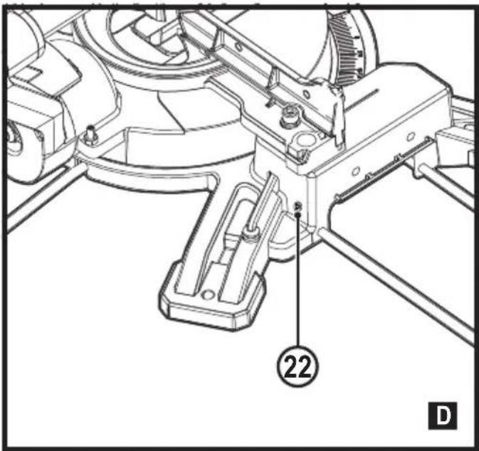
Table extension rail (Fig. C & D)
Your mitre saw is supplied with 2 table extension rails (5) to support long overhanging workpieces.
◆ Pull the table extension rail (5) to the required length for the workpiece as shown in figure C.
- Secure in position by tightening the extension rail locking screw (22), as shown in figure D.
◆ Repeat the process on opposite side.
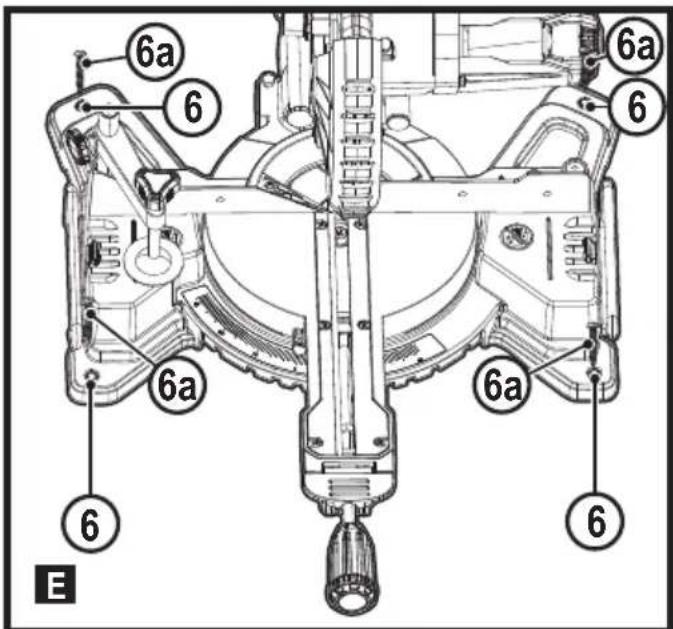
Bench mounting (Fig. E)
The mitre saw can be bolted with four bolts (6a) (not provided) to a level and stable surface using the bolt holes (6) provided in the tools base. This will help prevent tipping and possible injury.
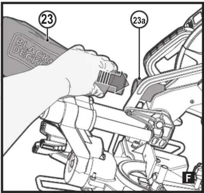
Dust collection (Fig. F)
The use of the dust bag (23) makes cutting operations clean and dust collection easy.
◆ To attach the dust bag (23), fit it onto the dust nozzle (23a).
- When the dust bag (23) is about half full, remove it from the tool.
◆ Empty the dust bag of its contents, tapping it lightly so as to remove particles adhering to the insides which might hamper further collection.
Note: If you connect a workshop vacuum to your saw, more efficient and cleaner operations can be performed.
To install workpiece clamp (Fig. G)
- Insert the clamp (4) into the hole (4c) behind the fence. The clamp should be facing toward the back of the miter saw. The groove on the clamp rod should be fully inserted into the base. Ensure this groove is fully inserted into the base of the miter saw. If the groove is visible, the clamp will not be secure. Secure the clamp rod by tightening the clamp locking screw (3)
- Rotate the clamp 180^ toward the front of the miter saw.
- Loosen the knob (4b) to adjust the clamp up or down, then use the fine adjust knob (4a) to firmly clamp the workpiece.
Note: Place the clamp on the opposite side of the base when beveling. ALWAYS MAKE DRY RUNS (UNPOWERED) BEFORE FINISH CUTS TO CHECK THE PATH OF THE BLADE. ENSURE THE CLAMP DOES NOT INTERFERE WITH THE ACTION OF THE SAW OR GUARDS.
Changing or installing a new saw blade (Fig. H, I, J)
Warning! To reduce the risk of serious personal injury, turn off the tool and disconnect it from the power source before attempting to move it, change accessories or make any adjustments.
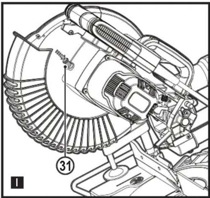
Warning! Never depress the spindle lock (31) button while the blade is under power or coasting.
Warning! Do not cut ferrous metal (containing iron or steel) or masonry or fiber cement product with this mitre saw.
Removing the blade
◆ Unplug the saw.
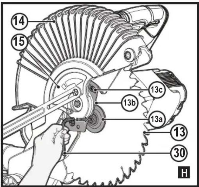
- Raise the arm to the upper position and push the guard (14) up as far as possible.
- Loosen, but do not remove guard bracket screw (13c) until the bracket can be raised far enough to access the blade screw (13a). Lower guard will remain raised due to the position of the guard bracket screw as shown in figure H.
- Depress the spindle lock button (31) while carefully rotating the saw blade by hand until the lock engages as shown in figure I.
- Keeping the button depressed, use the other hand and the blade changing tool provided (30) to loosen the blade screw (13a). (Turn clockwise, left-hand threads.)
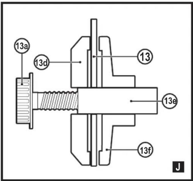
◆ Remove the blade screw (13a), outer clamp washer (13d), blade (13) and blade adapter (13e), if used. The inner clamp washer (13f) may be left on the spindle.
Installing a blade
◆ Unplug the saw.
- With the arm raised, the guard held open and the guard bracket raised, place the blade on the spindle, onto the blade adapter and against the inner blade clamp with the teeth at the bottom of the blade pointing toward the back of the saw.
◆ Assemble the outer clamp washer onto the spindle.
- Install the blade screw and, engaging the spindle lock, tighten the screw firmly with wrench provided (turn counterclockwise, left-hand threads).
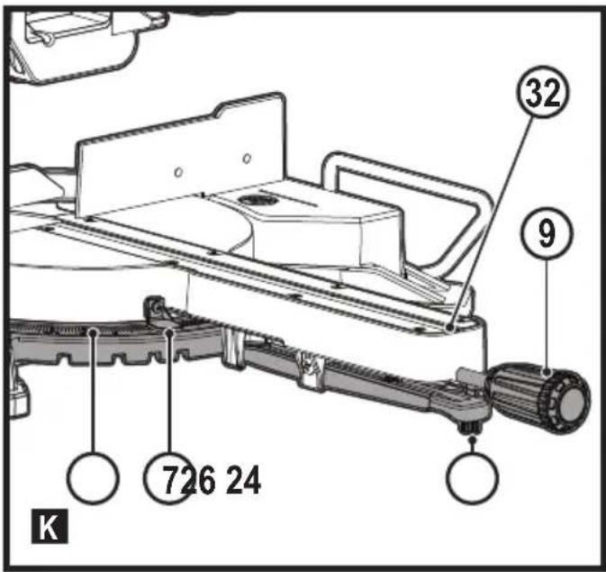
Adjusting the mitre angle (Fig. K)
◆ Loosen the grip (9) by turning counterclockwise.
Use the mitre lock release (32) to move the rotary table (11) to the position where the pointer (7) points to the desired angle on the mitre scale (26), tighten the grip clockwise.
- The adjustable support foot (24) is to help keep the tool in balance. After each mitre angle adjustment, you should turn knob on the foot clockwise or counterclockwise until its bottom touches the ground. There are two positions depending on the depth of your work bench.
Cutting depth
If you want to cut a groove you can set the depth of cut using the depth of cut screw (29) or the blade.
- Turn the depth of cut screw (29) and fix with the counter nut.
The depth stop allows the depth of cut of the blade to be limited. The stop is useful for applications such as grooving and tall vertical cuts. To adjust the depth stop, loosen the locking nut and adjust the depth adjustment screw to set the desired depth of cut. To secure the adjustment, tighten the locking nut.
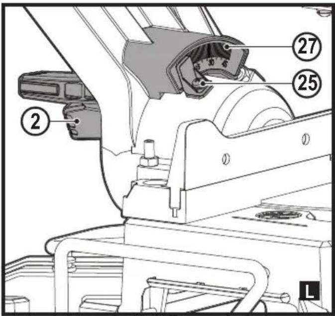
Adjusting the bevel angle (Fig. L)
When tilting the carriage to the left, loosen the lever (2) at the rear of the tool counterclockwise. Unlock the arm by pushing the handle somewhat strongly in one direction only.
◆ Tilt the saw blade until the pointer (25) points to the desired angle on the bevel scale (27).
◆ Tighten the lever (2) clockwise firmly to secure the arm.
Warning! When tilting the saw blade, be sure to raise the handle fully. After changing the bevel angle, always secure the arm by tightening the lever clockwise.
Warning! When tilting the saw blade, always be aware of the weight of the head and make sure to avoid it crashing over.
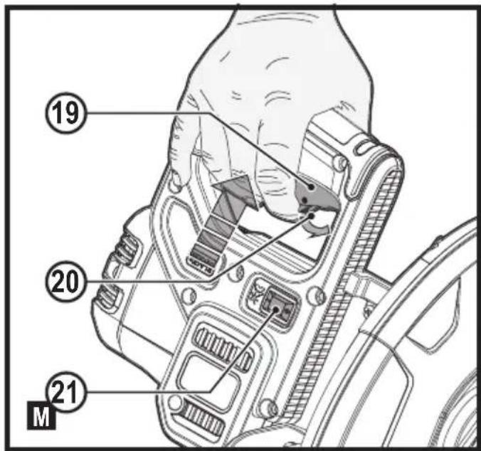
Switch action (Fig. M)
Caution! Before plugging in the tool, always check to see that the switch trigger (19) actuates properly and returns to the "OFF" position when released.
◆ To start the tool, move the safety release lever (20) to the right with your index finger.
◆ Press the switch trigger (19).
◆ To stop the tool, release the switch trigger (19).
Warning! Never use tool without a fully operative switch trigger. Any tool with an inoperative switch is HIGHLY DANGEROUS and must be repaired before usage.
Use of Cut line System
Note: The mitre saw must be connected to a power source. The Cut line System is equipped with an on/off switch (21). The Cut line System is independent of the mitre saw's trigger switch.
The light does not need to be on in order to operate the saw. To cut through an existing pencil line on a piece of wood:
- Turn on the Cut line system, then pull down on the operating handle (18) to bring the saw blade close to the wood. The shadow of the blade will appear on the wood.
Align the pencil line with the edge of the blade's shadow. You may have to adjust the mitre or bevel angles in order to match the pencil line exactly.
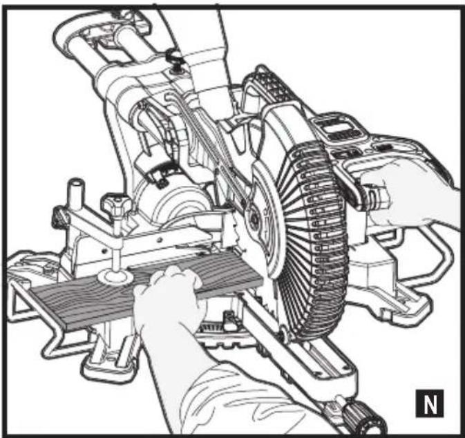
Crosscuts (Fig. N)
A crosscut is made by cutting wood across the grain at any angle. A straight crosscut is made with the miter arm at the zero degree position. Set and lock the miter arm at zero, hold the wood firmly on the table and against the fence.
With the rail lock knob tightened, turn on the saw by squeezing the trigger switch (19).
When the saw comes up to speed (about 1 second) lower the arm smoothly and slowly to cut through the wood. Let the blade come to a full stop before raising arm.
When cutting anything larger than a 51mm x 102mm, use an out-down-back motion with the rail lock knob loosened.
Pull the saw out, toward you, lower the saw head down toward the workpiece, and slowly push the saw back to complete the cut. Do not allow the saw blade to contact the top of the workpiece while pulling out. The saw may run toward you, possibly causing personal injury or damage to the workpiece.
Warning! Always use a work clamp to maintain control and reduce the risk of workpiece damage and personal injury.
Note: The rail lock knob must be loose to allow the saw to slide along its rails.
Miter crosscuts are made with the miter arm at some angle other than zero. This angle is often 45^ for making corners, but can be set anywhere from zero to 47^ left or 47^ right. Make the cut as described above.
To cut through an existing pencil line on a piece of wood, match the angle as close as possible. Cut the wood a little too long and measure from the pencil line to the cut edge to determine which direction to adjust the miter angle and recut. This will take some practice, but it is a commonly used technique.
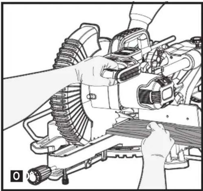
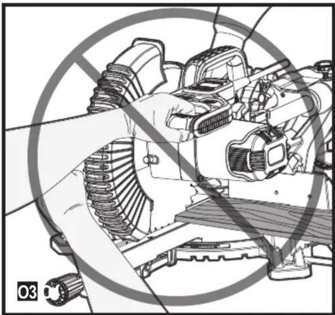
Body and hand position (Fig. O - O3)
Proper positioning of your body and hands when operating the miter saw will make cutting easier, more accurate and safer.
Never place hands near cutting area.
Place hands no closer than 152 mm from the blade. Hold the workpiece tightly to the table and the fence when cutting.
Keep hands in position until the trigger has been released and the blade has completely stopped. ALWAYS MAKE DRY RUNS (UNPOWERED) BEFORE FINISH CUTS SO THAT YOU CAN CHECK THE PATH OF THE BLADE.
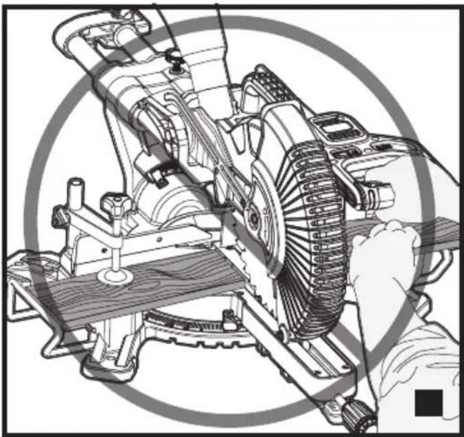
DO NOT CROSS HANDS, AS SHOWN IN FIGURE O3 and O4.
Keep both feet firmly on the floor and maintain proper balance. As you move the miter arm left and right, follow it and stand slightly to the side of the saw blade. Sight through the guard louvers when following a pencil line.
Bevel square to table adjustment (Fig. O4)
To align the blade square to the table, lock the arm in the down position with the lock down pin. Place a square against the blade, ensuring the square is not on top of a tooth. Loosen the bevel lock knob and ensure the arm is firmly against the 0° bevel stop. Rotate the 0° bevel adjustment screw with the 10 mm spanner (not provided) as necessary so that the blade is at 0° bevel to the table, as measured with the square.
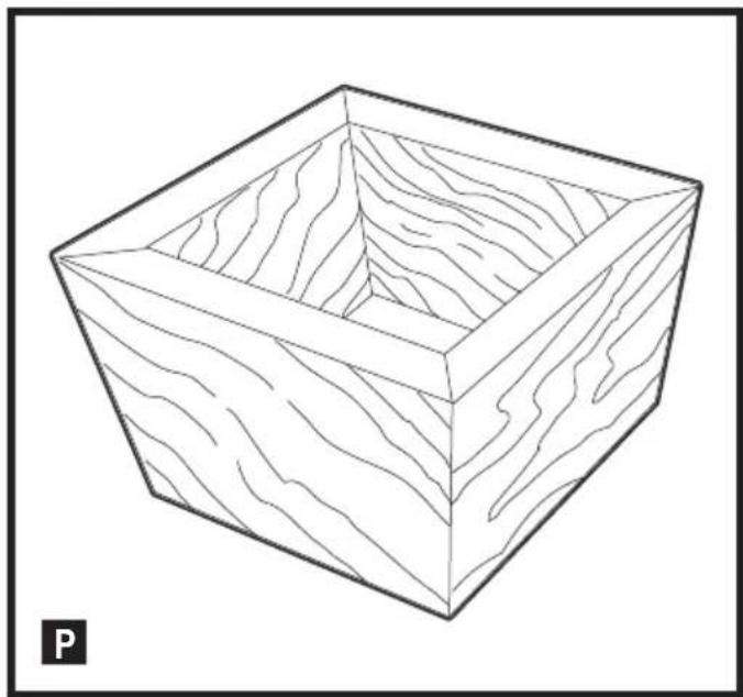
Cutting picture frames, shadow boxes and other four-sided projects (Fig. P, P1, P2)
To best understand how to make the items listed here, we suggest that you try a few simple projects using scrap wood until you develop a "feel" for your saw.
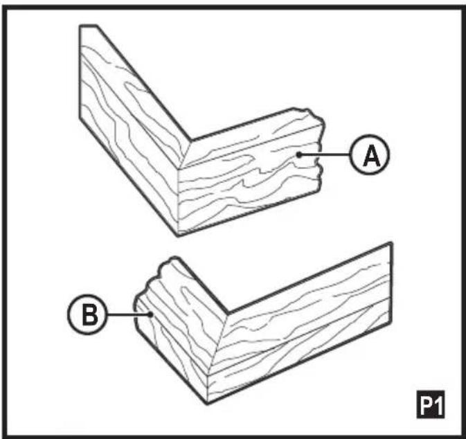
Your saw is the perfect tool for mitering corners like the one shown in Figure P. Sketch A in Figure P1 shows a joint made by using the bevel adjustment to bevel the edges of the two boards at 45^ each to produce a 90^ corner. For this joint the miter arm was locked in the zero position and the bevel adjustment was locked at 45^ . The wood was positioned with the broad flat side against the table and the narrow edge against the fence. The cut could also be made by mitering right and left with the broad surface against the fence.
Cutting trim molding and other frames (Fig. P1)
Sketch B in Figure P1 shows a joint made by setting the miter arm at 45^ to miter the two boards to form a 90^ corner. To make this type of joint, set the bevel adjustment to zero and the miter arm to 45^ . Once again, position the wood with the broad flat side on the table and the narrow edge against the fence.
Figures P1 and P2 are for four-sided objects only.
As the number of sides changes, so do the miter and bevel angles.
The chart below gives the proper angles for a variety of shapes.
| Number of Sides Miter | or Bevel Angle |
| 4 45° | |
| 5 36° | |
| 6 30° | |
| 7 25.7° | |
| 8 22.5° | |
| 9 20° | |
| 10 18° | |
The chart assumes that all sides are of equal length. For a shape that is not shown in the chart, use the following formula: 180^ divided by the number of sides equals the miter (if the material is cut vertically) or bevel angle (if the material is cut laying flat).
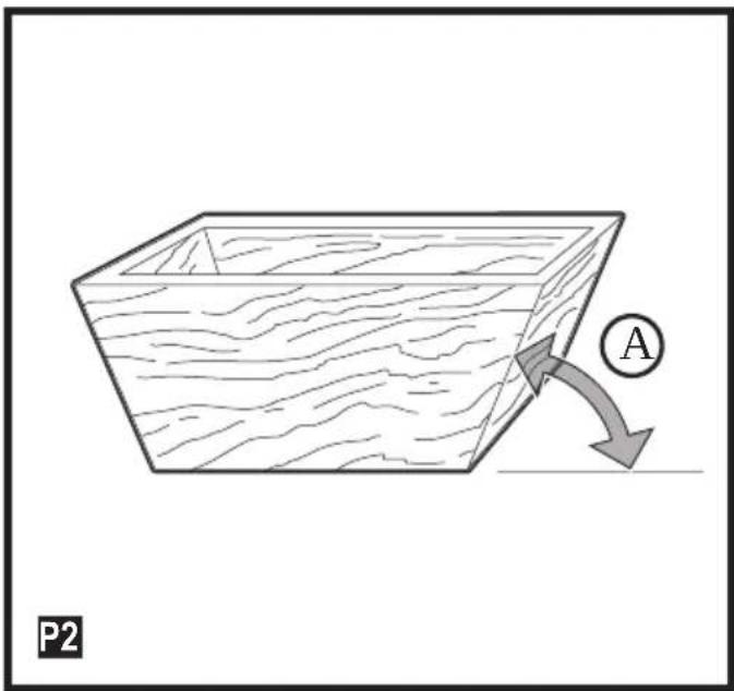
Cutting compound miters (Fig. P2)
A compound miter is a cut made using a miter angle and a bevel angle at the same time. This is the type of cut used to make frames or boxes with slanting sides like the one shown in figure P2.
Note: If the cutting angle varies from cut to cut, check that the bevel lock knob and the miter lock handle are securely locked. These must be locked after making any changes in bevel or miter.
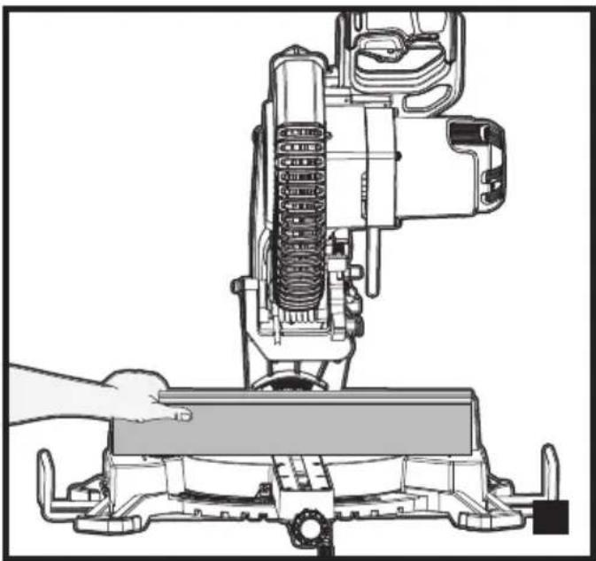
Cutting base molding (Fig. Q)
Straight 90° cuts:
Position the wood against the fence and hold it in place as shown in Figure Q. Turn on the saw, allow the blade to reach full speed and lower the arm smoothly through the cut.
Position material as shown in Figure O. All cuts should be made with the back of the molding against the fence and with the bottom of the molding against the table.
| Inside Corner Outside Corner |
| Left Side Miter | left 45°Save left side of cut | Miter right 45°Save left side of cut |
| Right Side Miter | right 45°Save right side of cut | Miter left 45°Save right side of cut |
Material up to 70 mm can be cut as described above.
BES701 - 70 mm for 216 mm
Cutting crown molding
In order to fit properly, crown molding must be compound mitered with extreme accuracy.
The two flat surfaces on a given piece of crown molding are at angles that, when added together, equal exactly 90^ . Most, but not all, crown molding has a top rear angle (the section that fits flat against the ceiling) of 52^ and a bottom rear angle (the part that fits flat against the wall) of 38^ .
Your miter saw has special pre-set miter detent points at 31.6° left and right for cutting crown molding at the proper angle. There is also a mark on the bevel scale at 33.9°.
The Bevel Setting/Type of Cut chart gives the proper settings for cutting crown molding. (The numbers for the miter and bevel settings are very precise and are not easy to accurately set on your saw.) Since most rooms do not have angles of precisely 90°, you will have to fine tune your settings anyway.
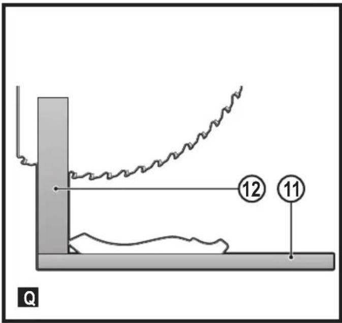
Instructions for cutting crown molding laying flat and using the compound features
◆ Lay the molding with broad back surface down flat on saw table (fig. Q).
- The settings below are for all Standard crown molding with 52° and 38° angles.
| Bevel Setting Type Of Cut |
| 33.9° | LEFT SIDE, INSIDE CORNER:1. Top of molding against fence2. Miter table set right 31.6°3. Save left end of cut |
| 33.9° | RIGHT SIDE, INSIDE CORNER:1. Bottom of molding against fence2. Miter table set left 31.6°3. Save left end of cut |
| 33.9° | LEFT SIDE, OUTSIDE CORNER:1. Bottom of molding against fence2. Miter table set left 31.6°3. Save right end of cut |
| 33.9° | RIGHT SIDE, OUTSIDE CORNER:1. Top of molding against fence2. Miter table set right 31.6°3. Save right end of cut |
Note: When setting bevel and miter angles for all compound miters, remember that the angles presented for crown moldings are very precise and difficult to set exactly. Since they can easily shift slightly and very few rooms have exactly square corners, all settings should be tested on scrap molding.
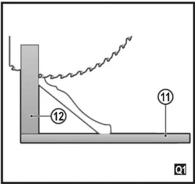
Alternative method for cutting crown molding
Place the molding at an angle between the fence (12) and the saw table (11), with the top side of the molding on the table and the bottom side of the molding on the fence as shown in figure Q1.
The advantage to cutting crown molding using this method is that no bevel cut is required. Minute changes in the miter angle can be made without affecting the bevel angle. This way, when corners other than 90^ are encountered, the saw can be quickly and easily adjusted for them.
Instructions for cutting crown molding angled between the fence and base of the saw for all cuts
This saw can cut up to 14 mm x 92 mm crown molding nested.
- Angle the molding so the bottom of the molding (part which goes against the wall when installed) is against the fence (12) and the top of the molding is resting on the saw table (11), as shown in figure Q1.
- The angled "flats" on the back of the molding must rest squarely on the fence and saw table.
| Inside Corner Outside | Corner |
| Left Side Miter right at 45°Save right side of cut | Miter left at 45°Save right side of cut |
| Right Side Miter left at 45°Save left side of cut | Miter right at 45°Save left side of cut |
Special Cuts
Never make any cut unless the material is secured on the table and against the fence.
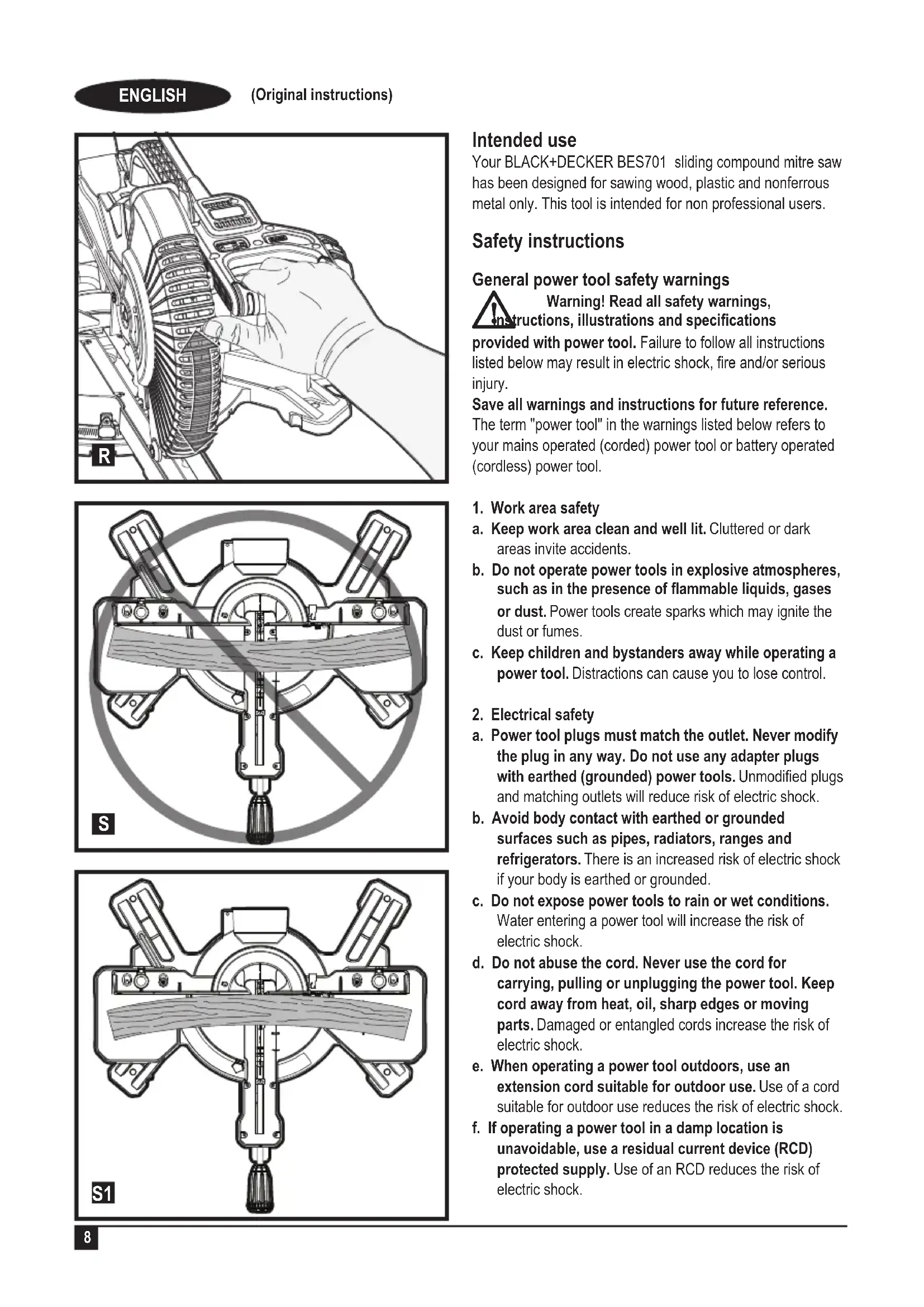
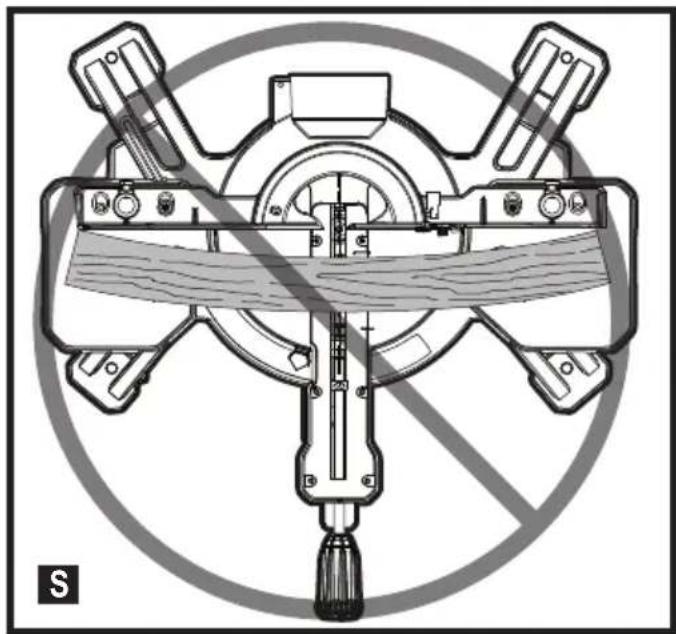
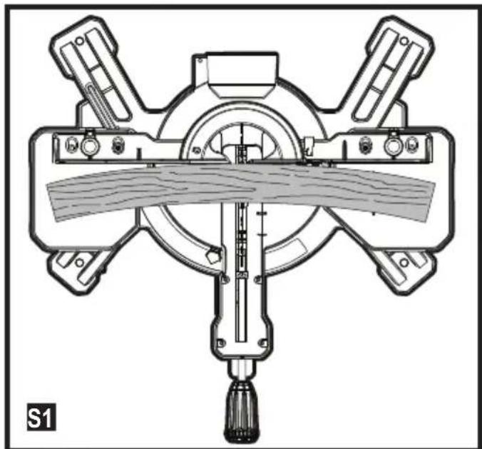
Bowed material (fig. S, S1)
When cutting bowed material always position it as shown in figure S1 and never like that shown in figure S. Positioning the material incorrectly will cause it to pinch the blade near the completion of the cut.
Cutting round material
Rounded material should be clamped or held firmly to the fence to keep It from rolling. This is extremely important when making angle cuts.
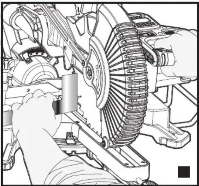
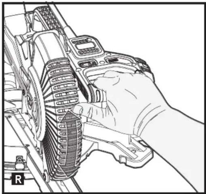
Cutting large material
Occasionally you will encounter a piece of wood a little too large to fit beneath the lower guard.
To clear the guard over the wood, with the saw off and your right hand on the operating handle, place your right thumb outside of the upper portion of the guard and roll the guard up just enough to clear the wood, as shown in figure R. Release the guard prior to starting the motor. The guard mechanism will function properly during the cut. Only do this when necessary.
NEVER TIE, TAPE, OR OTHERWISE HOLD THE GUARD OPEN WHEN OPERATING THIS SAW.
Warning! Always be sure that the tool is switched off and unplugged before adjusting or checking the tools function.
After use
- After use, wipe off chips and dust adhering to the tool with a cloth or the like.
- Keep the blade guard clean according to the directions in the previously covered section.
- Lubricate the sliding portions with machine oil to prevent rust.
- When storing the tool, pull the carriage toward you fully.
◆ Make sure the tool is unplugged.
◆ Secure the blade at the 0^ bevel angle and turn the base to the right mitre angle fully
- Secure the slide bars after pulling the carriage toward you fully.
◆ Lower the handle fully and lock it in the position by pushing in the saw head locking pin (17).
◆ Carry the tool by holding under the base.
◆ If you remove the clamp, dust bag, etc., you can carry the tool more easily.
- Carry the tool by with both hands holding the tool base.
Caution! Always secure all moving portions before carrying the tool.
Saw head locking pin (17) is for carrying and storage purposes only and not for any cutting operations.
Troubleshooting
| Problem Possible Cause Solution | |
| Motor does not start | Saw not plugged in. Check that all cords are plugged in. |
| Angle of cut inaccurate | Mitre table unlocked. | Use mitre table locking lever (see Adjusting the mitre angle section. |
| Too much sawdust under table. | Vacuum or blow out dust. Wear eye protection. |
| Cutting arm cannot fully raise, or blade guard cannot fully close | Parts Failure. Contact service centre. |
| Pivot spring not replaced properly after service. | Contact service centre. |
| Sawdust build up. Clean and lubricate moving parts. |
| Saw head locking pin not set properly. | Check, adjust, and properly set saw head locking pin. |
| Blade binds, jams or shakes | Saw blade damaged. | Replace blade. |
| Dull blade. Replace or sharpen blade. |
| Improper blade. Replace blade. |
| Warped blade. Replace blade. |
| Saw vibrates or shakes | Saw blade damaged. | Replace blade. |
| Saw blade loosened. | Tighten arbor bolt. |
| Saw not properly fastened down. | Fasten saw to bench, stand or table. |
| Work piece not properly supported. | Properly support or clamp work piece. |
Protecting the environment

Separate collection. Products and batteries marked with this symbol must not be disposed of with normal household waste.
Products and batteries contain materials that can be recovered or recycled reducing the demand for raw materials. Please recycle electrical products and batteries according to local provisions. Further information is available at www.2helpU.com
Technical data
| BES701 Type 1 |
| Voltage V 230 | | |
| Speed /min 4800 | | |
| Blade outer diameter mm | | 216 |
| Bore diameter | mm | 30 |
| Weight kg | 12.1 | |
| Blade thickness | mm | 2.6 |
| Blade max. kerf | mm | 2.8 |
| Mitre (max. positions) | ° | +/- 47 |
| Bevel (max. positions) | ° | 47 |
| Max. cross-cut capacity at 90 ° | mm | 220 |
| Max mitre capacity at 45 ° | mm | 155 |
| Max. dept cut at 90 ° | mm | 70 |
| Max. dept cut at 45 ° | mm | 40 |
| BES701 - Level of sound pressure according to EN 62841: |
| L_pA (sound pressure) 98 dB(A), Uncertainty (K) 3 dB(A) |
| L_wA (sound power) 108.0 dB(A), Uncertainty (K) 3 dB(A) |
Supply of Machinery (Safety) Regulations 2008

BES701 Sliding Compound Mitre Saw
Black & Decker declares that these products described under "technical data" are in compliance with:
The Supply of Machinery (Safety) Regulations, 2008, S.I.
2008/1597 (as amended),
EN62841-1:2015, EN 62841-3-9:2020+A11:2020
These products conform to the following UK Regulations:
Electromagnetic Compatibility Regulations, 2016,
S.I.2016/1091 (as amended).
The Restriction of the Use of Certain Hazardous Substances in Electrical and Electronic Equipment Regulations 2012, S.I. 2012/3032 (as amended).
For more information, please contact Black & Decker at the following address or refer to the back of the manual.
The undersigned is responsible for compilation of the technical file and makes this declaration on behalf of
Black & Decker

Ed Higgins
Director - Consumer Power Tools
Black & Decker UK, 270 Bath Road, Slough
Berkshire, SL1 4DX
United Kingdom
14/01/2022
MACHINERY DIRECTIVE

BES701 Sliding Compound Mitre Saw
Black & Decker declares that these products described under "technical data" are in compliance with: 2006/42/EC, EN62841-1:2015, EN 62841-3-9:2020+A11:2020
These products also comply with Directive 2014/30/EU and 2011/65/EU.
For more information, please contact Black & Decker at the following address or refer to the back of the manual.
The undersigned is responsible for compilation of the technical file and makes this declaration on behalf of Black & Decker.
Patrick Dippelbuch
Patrick Diepenbach
General Manager, Benelux
Black & Decker,
Black & Decker is confident of the quality of its products and offers consumers a 24 month guarantee from the date of purchase. This guarantee is in addition to and in no way prejudices your statutory rights. The guarantee is valid within the territories of the Member States of the European Union with European Free Trade Area and the United Kingdom.
To claim on the guarantee, the claim must be in accordance with Black & Decker Terms and Conditions and you will need to submit proof of purchase to the seller or an authorised repair agent. Terms and conditions of the Black & Decker 2 year guarantee and the location of your nearest authorised repair agent can be obtained on the Internet at www.2helpU.com, or by contacting your local Black & Decker office at the address indicated in this manual.
Please visit our website www.blackanddecker.co.uk to register your new BLACK+DECKER product and receive updates on new products and special offers.
General Manager, Benelux
Black & Decker,
General Manager, Benelux
Black & Decker,
General Manager, Benelux
Black & Decker,
General Manager, Benelux
Black & Decker,
Director General, Benelux
Black & Decker,
Director-Geral, Benelux
Black & Decker,
General Manager, Benelux
Black & Decker,
Tverrkutting (figur N)
General Manager, Benelux
Black & Decker,
- Tilt the saw blade until the pointer (25) points to the desired angle on the bevel scale (27).
♦ Stram grebet (2) godt mod uret for at fastgøre armen.