Micro Cinema Camera - Camera Blackmagic Design - Free user manual and instructions
Find the device manual for free Micro Cinema Camera Blackmagic Design in PDF.
| Product Type | Compact Digital Camera |
| Lens Compatibility | Micro Four Thirds Mount |
| Sensor | Super 16, 13-stop dynamic range |
| Maximum Resolution | 1080p (up to 60 fps) |
| Recording Formats | ProRes (HQ, 422, LT, Proxy), CinemaDNG RAW, RAW 3:1 |
| ISO Sensitivity | 200 to 1600 (default 800) |
| Shutter Angle | Default 180°, adjustable from 1° to 360° |
| White Balance | Presets from 2500K to 8000K |
| Frame Rates | 23.98, 24, 25, 29.97, 30, 50, 59.94, 60 fps |
| Power | LP-E6/LP-E6N battery, 12-20V DC adapter, 12V expansion port |
| Battery Life | Varies by battery; camera auto-powers when AC adapter is connected |
| Video Outputs | HDMI (micro), composite video (RCA via expansion cable) |
| Audio Input | 3.5mm stereo jack (mic/line), LTC timecode |
| Expansion Port | DB-HD15: power input, reference, LANC, PWM/LANC servo, S.Bus, composite video |
| Tally Light | White (on), red (recording), green (SD ready) |
| Storage | SD/SDHC/SDXC card (Class 10 UHS-I recommended) |
| Dimensions (approx) | 106 x 60 x 30 mm |
| Weight (approx) | 235 g (body only) |
| Included Software | DaVinci Resolve (full version), Blackmagic Camera Setup |
| Menu Languages | French, English, Chinese, Japanese, etc. |
| Warranty | 1 year, limited to manufacturing defects |
| Maintenance and Cleaning | Keep dust cap in place; clean lens with soft cloth; format SD cards regularly |
| Safety | Do not expose sensor to sunlight; use recommended batteries; turn off before changing lens |
| Spare Parts and Repairability | LP-E6/LP-E6N batteries, expansion cable, LANC remotes; repair by Blackmagic Design or authorized center |
Frequently Asked Questions - Micro Cinema Camera Blackmagic Design
User questions about Micro Cinema Camera Blackmagic Design
0 question about this device. Answer the ones you know or ask your own.
Ask a new question about this device
Download the instructions for your Camera in PDF format for free! Find your manual Micro Cinema Camera - Blackmagic Design and take your electronic device back in hand. On this page are published all the documents necessary for the use of your device. Micro Cinema Camera by Blackmagic Design.
USER MANUAL Micro Cinema Camera Blackmagic Design
Installation and Operation Manual
Blackmagic Design Compact Cameras
May 2018
English, 日本語, Français, Deutsch, Español, 中文, 한국어, Русский, Italiano, Português and Türkçe.
Languages
To go directly to your preferred language, simply click on the hyperlinks listed in the contents below.
English 3
日本語 66
Français 130
Deutsch 194
Español 258
中文 322
한국어 386
Русский450
Italiano 514
Português 578
Türkçe 642

natural_image
Circular portrait photo of a smiling man in a dark shirt against a gray background (no text or symbols)Welcome
Thank you for purchasing your Blackmagic Camera!
Our Blackmagic Pocket Cinema Camera is a Super 16 digital film camera with 13 stops of dynamic range that is small enough to take anywhere. Blackmagic Micro Cinema Camera takes the size and capability of the Blackmagic Pocket Cinema Camera even further. With an incredibly tiny chassis and a customizable expansion port complete with a host of remote control options, now you can capture footage from practically any angle and in tricky locations.
Our cameras are designed to produce files that are "flat," which means they preserve the wide dynamic range from the sensor, as well as standard file formats that work with all video software. This allows you to make creative decisions by using the included DaVinci color correction software!
We think this means you get a cinema style shooting experience where you capture and preserve more of the image so you have as many creative options as possible. We have also included large screens on our cameras for easy focus and metadata entry. We hope you connect to our cameras in creative ways and produce some amazing looking images! We are extremely excited to see what creative work you produce!
Grant Petty
Grant Petty
CEO Blackmagic Design
Contents
Blackmagic Design Compact Cameras
Getting Started 5
Attaching a Lens 5
Turning Your Camera On 6
Installing Media 7
Using an SD Card 7
About SD Cards 8
Choosing a Fast SD Card 8
Preparing Media for Recording 9
Checking Disk Speed 12
Recording
Recording Clips 12
Trigger Record 13
Playback
Playing Back Clips 14
Camera Connections 15
Blackmagic Pocket Cinema Camera 15
Blackmagic Micro Cinema Camera 16
Wiring Diagram for the
Blackmagic Micro Cinema
Camera Expansion Cable 18
Tally Light Indicators 19
Blackmagic Micro Cinema
Camera Tally Light 19
Menu Settings 20
Dashboard 20
Camera Settings 20
Audio Settings 23
Recording Settings 25
File Naming Convention 27
Display Settings 27
Remote Settings 31
On Screen Meters 33
Adjusting Settings 35
Status Strip 36
Entering Metadata 38
What is the Slate? 38
Using DaVinci Resolve 39
Importing your Clips 40
Working with RAW files 40
Editing your Clips 42
Trimming Clips 43
Mapping Keyboard Shortcuts 44
Adding Transitions 45
Adding Titles 46
Color Correcting your Clips 46
Using Scopes 47 _12
Secondary Color Correction 49
Qualifying a Color 49
Adding a Power Window 14 50
Tracking a Window 51
Using Plugins 51
Mixing Your Audio 52
The Fairlight Page 53
The Audio Timeline 53
What is a Bus? 54
The Mixer 54
Using the Equalizer to
Enhance your Audio 55
Mastering your Edit 57
Camera Video Output 58
Blackmagic Camera Setup Software 58
Post Production Workflow 59
Working with Files from SD Cards 59
Working with 3rd Party Software 60
Using Final Cut Pro X 60
Using Avid Media Composer 61
Using Adobe Premiere Pro CC 61
Using Autodesk Smoke 62
Attaching Accessories 63
Help 64
Warranty 65
Getting Started
Blackmagic Design compact cameras, such as Blackmagic Pocket Cinema Camera and Blackmagic Micro Cinema Camera, are small portable digital cinema cameras that record high quality HD images on fast SD cards.
Your compact camera is capable of recording clips using professional codecs designed for post production including ProRes and uncompressed CinemaDNG RAW.
Getting started is as simple as attaching a lens and powering your camera.
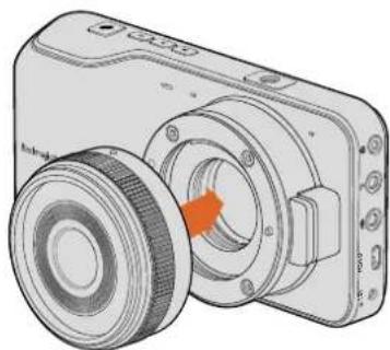
Attaching a Lens
Your Blackmagic compact camera uses micro four thirds lenses. These lenses are very popular and affordable, and there is an enormous range to choose from.
To remove the protective dust cap from your camera's lens mount, hold down the locking button and rotate the cap counterclockwise until it is released. We recommend always turning off your Blackmagic camera prior to attaching or removing a lens.
To attach a lens:
1 Align the dot on your lens with the dot on the camera mount. Many lenses have a visual indicator, for example a red dot.
2 Press the lens mount against the camera mount, and twist the lens clockwise until it clicks into place.
3 To remove the lens, hold down the locking button, rotate the lens counterclockwise until its dot or indicator reaches the 12 o'clock position, and gently remove.
natural_image
Illustration of a digital camera with a circular lens and orange arrow indicating rotation (no text or symbols)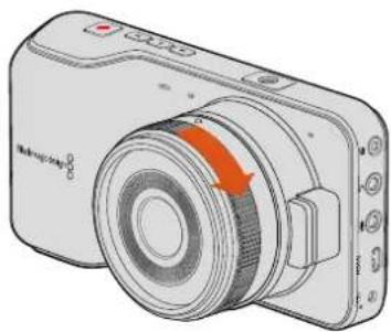
natural_image
Illustration of a digital camera with an orange arrow indicating rotation (no text or symbols present)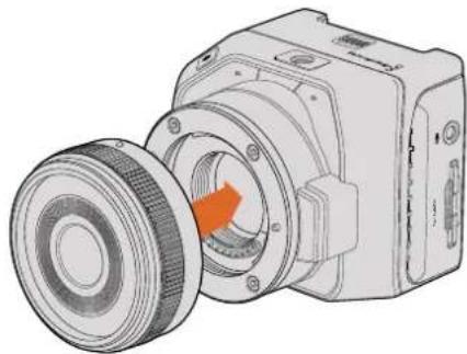
natural_image
Technical illustration of a mechanical device with a circular component and orange arrow indicating rotation (no text or symbols)
natural_image
Illustration of a digital camera with an orange arrow indicating rotation (no text or symbols present)Attaching and removing an MFT lens on Blackmagic Pocket Cinema Camera and Blackmagic Micro Cinema Camera
NOTE When no lens is attached to the camera, the glass filter covering the sensor is exposed to dust and other debris so you'll want to keep the dust cap on whenever possible.
Turning Your Camera On
To turn your camera on, you'll first need to supply power to your camera.
Blackmagic Pocket Cinema Camera and Micro Cinema Camera can be powered by plugging the supplied power adapter into their power input. This also recharges the removable, rechargeable batteries.
TIP The Micro Cinema Camera powers up automatically when power is supplied via an AC adapter using the expansion port. This means that if you have the camera installed in a remote location or mounted in an awkward or inconvenient position to access, you don't have to manually turn the camera on because as long as it is connected to an external power supply, it will always stay powered on.
Inserting a Battery and Powering Blackmagic Pocket Cinema Camera
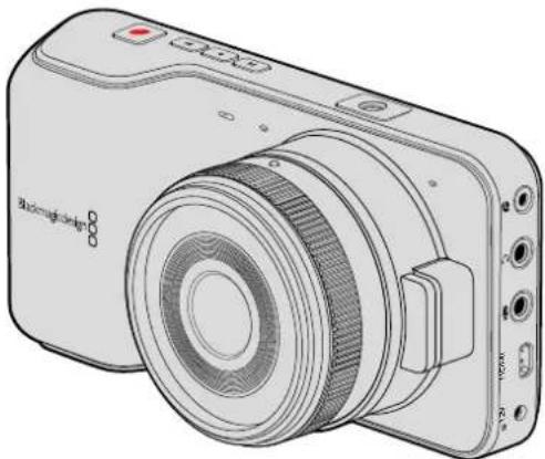
Your Pocket Cinema Camera uses an EN-EL20 battery. One is included with the camera, but if you need additional batteries, they can be purchased from your Blackmagic Design reseller or from most video or photography equipment stores.
1 On the under side of the camera, push the door release towards the lens to access the battery terminal.
2 With the gold contacts facing into the terminal and the white arrow facing the lens, hook the lip of the battery under the orange tab and insert the battery until you feel it press into place. Push the orange tab to release the battery.
3 Close the door to the battery terminal and slide the door release to the right to lock it.
4 Press the power button on the bottom right of the back panel. The status strip will appear along the top of the LCD.
5 Press and hold the power button to switch off the camera.
natural_image
Diagram of a camera module with orange rotation arrow indicating assembly (no text or symbols)Inserting the battery Into Blackmagic Pocket Cinema Camera
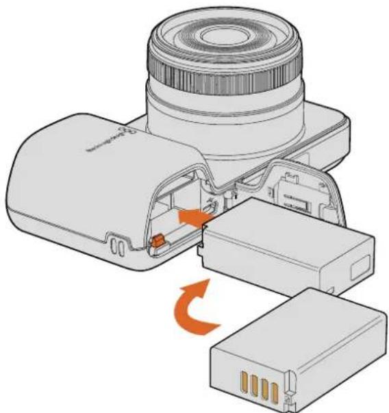
Inserting a Battery and Powering Blackmagic Micro Cinema Camera
Your Micro Cinema Camera uses an LP-E6 or LP-E6N battery. One is included with the camera but if you need additional batteries, they can be purchased from your Blackmagic Design reseller or from any video or photography equipment store.
1 With the battery's contacts facing the bottom of the camera, gently press the battery against the battery slot, then slide it down until you feel it click and lock into place. Press the battery release button on the top panel to remove the battery.
2 To switch on your camera, press the 'power' button located on the right panel of the camera. To switch off, press and hold the 'power' button.
You are now ready to insert an SD card and start recording!
Installing Media
Your Blackmagic Camera uses readily available SD cards to record high quality HD video, including high bit rate RAW CinemaDNG clips.
NOTE SD cards are available in a range of speeds and capacities, not all of which as suitable for recording high bit rate video. To ensure reliable recording at your chosen resolution and video quality, use only the recommended SD cards listed in the 'about SD cards' section of this manual, or check the Blackmagic Design website for the latest information. www.blackmagicdesign.com
Using an SD Card
Your Blackmagic compact camera supports fast SDXC and SDHC cards. To insert an SD card into your camera:
Blackmagic Pocket Cinema Camera
On the underside of the camera, push the battery door release towards the lens. The SD card slot is located next to the battery terminal. With the metal contacts on the SD card facing towards the lens, insert the SD card until you feel it lock into place. Push on the SD card to release it.
After inserting the SD card and powering your camera, the status strip will display a moving dot while the camera checks the SD card and then it will say 'ready'.
natural_image
Technical illustration of a camera module with lens and internal components (no text or symbols)Inserting an SD card into the Blackmagic Pocket Cinema Camera
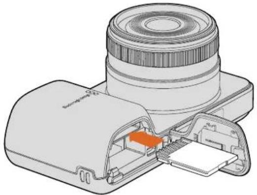
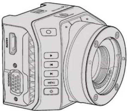
Blackmagic Micro Cinema Camera
With the SD card's metal contacts facing away from the lens, point the SD card towards the SD card slot and gently insert the card until you feel it lock into place. Push on the SD card to release it. The front tally light on the Micro Cinema Camera will flash green three times while the camera checks the SD card and will stay green when the card is ready.
The supplied SD card is for software installation only and not suitable for video recording. You'll find a list of recommended SD cards in the 'about SD cards' section.

natural_image
Diagram of a digital camera with lens and external connector (no text or symbols)Inserting an SD card into the Blackmagic Micro Cinema Camera
About SD Cards
Choosing a Fast SD Card
It's important to use SDHC and SDXC cards. These cards are rated for fast data speeds and support larger storage sizes.
We have provided a table showing SD cards that have tested reliable for video recording and playback. From a quick glance you can see which SD card is fast enough to handle a chosen format.
Please check the tech notes at the Blackmagic Design support center for the latest information.
| Brand SD Card Name/Type Storage Supported Formats | RAW ProRes | |||
| Delkin Devices | Elite SDHC UHS-I | 32GB | No | Yes |
| Elite SDHC UHS-I | 16GB | No | Yes | |
| SanDisk | Extreme Pro. 95 MB/sec SDXC UHS-I 512GB Yes YesExtreme Pro. 95 MB/sec SDXC UHS-I 256GB Yes YesExtreme Pro. 95 MB/sec SDXC UHS-I 128GB Yes YesExtreme Pro. 95 MB/sec SDXC UHS-I | 64GB | Yes | Yes |
| Extreme Pro. 95 MB/sec SDHC UHS-I | 32GB | Yes | Yes | |
| Extreme Plus. 80 MB/sec SDXC UHS-I | 128GB | Yes | Yes | |
| SanDisk | Extreme Plus. 80 MB/sec SDXC UHS-I | 64GB | No | Yes |
| Extreme Plus. 80 MB/sec SDXC UHS-I | 64GB | No | Yes | |
| Extreme Plus. 80 MB/sec SDHC UHS-I | 32GB | No | Yes | |
| Extreme Plus. 80 MB/sec SDHC UHS-I | 16GB | No | Yes | |
| Extreme Plus. 80 MB/sec SDHC UHS-I | 8GB | No | Yes | |
| Extreme. 45 MB/sec SDXC UHS-I | 128GB | No | Yes | |
| Extreme. 45 MB/sec SDXC UHS-I | 64GB | No | Yes | |
| Extreme. 45 MB/sec SDHC UHS-I | 32GB | No | Yes | |
| Extreme. 45 MB/sec SDHC UHS-I | 16GB | No | Yes | |
| Extreme. 45 MB/sec SDHC UHS-I | 8GB | No | Yes | |
Preparing Media for Recording
SD cards must be formatted as either HFS+ or exFAT. These disk formats allow long clips to be recorded as single files and can be formatted using the 'format disk' feature on the camera's dashboard, or using the 'settings menu' on Blackmagic Micro Cinema Camera. To see the 'settings menu' on Blackmagic Micro Cinema Camera, plug an HDMI monitor into the HDMI port or plug in a composite video display unit using the composite video out connector from the expansion cable.
TIP We recommend formatting SD cards in your Blackmagic camera for best results.
You can also format SD cards via a Mac or Windows PC.
HFS+ is also known as Mac OS Extended. It is the recommended format as it supports "journaling". Data on journaled media is more recoverable and less likely to be corrupted. HFS+ is natively supported by Mac OS X.
ExFAT is supported natively by Mac OS X and Windows without needing to purchase any additional software. However, exFAT does not support journaling which means data is less protected against the rare event your media card is corrupted.
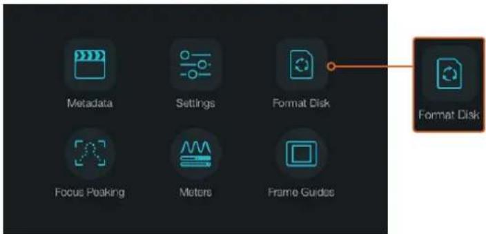
Select the 'format disk' or 'format card' icon on the camera dashboard to format your SD card
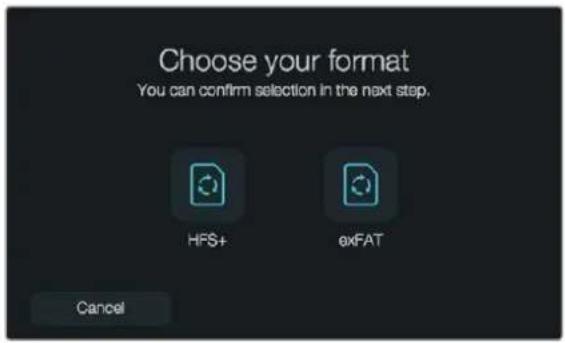
Choose from HFS+ or exFAT formats. Confirm your selection by tapping the 'yes, format my disk/card' icon to continue, or 'cancel' to cancel the format
Preparing SD cards using your camera
1 Press the 'menu' button to open the dashboard, or to open the settings menu on Blackmagic Micro Cinema Camera.
2 Select the 'format disk' or 'format card' icon using the navigation and 'ok' buttons on the Blackmagic Pocket Cinema Camera. On Blackmagic Micro Cinema Camera, press the 'right' arrow button to navigate through the settings and press the 'play' button to select 'setup' >'card'.
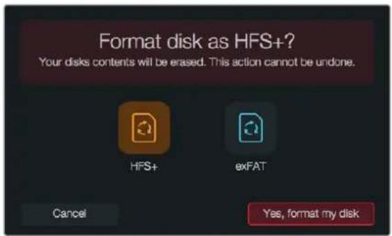
3 Choose your format by selecting the HFS+ or exFAT icon.
4 A warning will appear asking you to confirm the format. Select 'yes, format my disk/card' to continue, or 'cancel' to cancel the format.
5 A progress bar shows you the progress of the format. 'Complete' will appear when the format is done. It is important not to remove SD cards while they are formatting.
6 Select the 'done' icon to return to the dashboard, or press the 'menu' button on Blackmagic Micro Cinema Camera to return to the main menu settings.
Preparing SD cards on a Mac OS X computer
Use the 'disk utility' application included with Mac OS X to format or initialize your SD card in the HFS+ or exFAT formats. If your SD card already has files recorded on it, remember to back up your media as all data will be lost when it is formatted.
1 Plug an SD card into your computer's SD card slot or via an SD card reader.
2 Go to 'applications/utilities' and launch 'disk utility'.
3 Click on the disk icon of your SD card and then click the 'erase' tab.
4 Set the format to 'Mac OS extended (journaled)' or "exFAT".
5 Type a 'name' for the new volume and then click 'erase'. Your SD card will quickly be formatted and made ready for use.
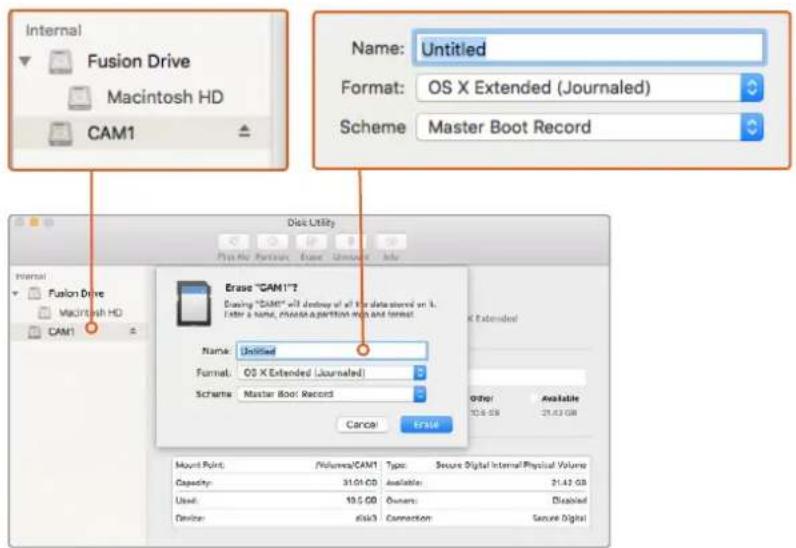
Use 'disk utility' on Mac OS X to erase your SD card in the Mac OS extended (journaled) or exFAT format
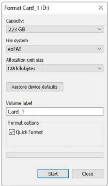
Use the 'format' dialog box feature in Windows to format your SD card in the exFAT format
Preparing SD cards on a Windows computer
The 'format' dialog box can format an SD card in the exFAT format on a Windows PC. Remember to back up anything important from your media as all data will be lost when it is formatted.
1 Plug an SD card into your computer's SD card slot or via an SD card reader.
2 Open the 'start menu' or 'start screen' and choose 'computer'. Right-click on your SD card.
3 From the contextual menu, choose 'format'.
4 Set the file system to 'exFAT' and the allocation unit size to 128 kilobytes.
5 Type a volume label, select 'quick format' and click 'start'.
6 Your SD card will quickly be formatted and made ready for use.
Checking Disk Speed
Blackmagic Disk Speed Test is a fun application that measures the read and write performance of storage media, then displays the results using video formats.
If you have ever wondered whether your hard drive is suitable for recording ("write") or playback ("read") of a particular video format, you can use Disk Speed Test to find out. Test the performance of your media with a single click of the 'start' button! Disk Speed Test will even show you how many streams of video your storage is capable of handling.
Disk Speed Test is installed by the Desktop Video Software. It is also available as a free download for Mac OS X from the Mac App Store.
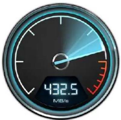
gauge
| Metric | Value | |--------|-----------| | Current | 432.5 |Use Disk Speed Test to find out the performance of your media
Recording
Recording Clips
Press the 'rec' button on your camera to begin recording immediately. Press 'rec' again to stop recording.
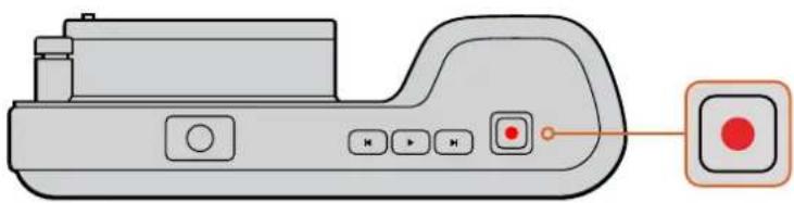
natural_image
Illustration of a handheld electronic device with control buttons and a highlighted indicator button (no text or symbols)To record a clip, press the 'rec' button on the top of Blackmagic Pocket Cinema Camera
Choosing the Recording Format
Blackmagic compact cameras record lossless compressed CinemaDNG RAW, plus Apple ProRes codecs including ProRes 422 HQ, ProRes 422, ProRes 422 LT and ProRes 422 Proxy. ProRes codecs let you fit more video on your SD card. ProRes 422 HQ provides the highest quality video with the lowest compression. Alternatively, ProRes 422 Proxy gives you far more recording time with greater compression.
Blackmagic Micro Cinema Camera also records RAW 3:1.
You may decide to experiment to see which format best suits your workflow.
To select your desired video format on Blackmagic Micro Cinema Camera:
1 Press the 'menu' button.
2 Select the 'camera' settings menu.
3 Select 'codec' and press the 'play' button. Use the forward and backward arrows to select a codec.
4 Press play again to confirm selection.
To select your desired video format on Blackmagic Pocket Cinema Camera:
1 Press the 'menu' button to open the dashboard and select Settings.
2 Select the 'recording' menu and use the selection arrows to set the desired recording format.
3 Press the 'menu' button twice to exit.
Your camera is now ready to record in the video format you have selected. On Blackmagic Pocket Cinema Camera, the current recording format is shown on the LCD status strip.
Blackmagic Cameras Supported Video Formats
| Blackmagic Pocket Cinema Camera Blackmagic Micro Cinema Camera | |
| 1080p23.98 1080p23.98 | |
| 1080p24 1080p24 | |
| 1080p25 1080p25 | |
| 1080p29.97 1080p29.97 | |
| 1080p30 1080p30 | |
| -1080p50 | |
| -1080p59.94 | |
| -1080p60 | |
Trigger Record
Blackmagic Micro Cinema Camera automatically sends a signal via the HDMI output that will trigger recording when connected to equipment that supports the trigger record feature, such as Blackmagic Video Assist.
This means that when you press record on your Micro Cinema Camera, your external recorder will also start recording, then will stop recording when you stop recording on the camera.
Blackmagic Micro Cinema Camera will also output timecode via HDMI, which means that the clips recorded on your external recorder will have the same timecode as the clips recorded in your camera.
You will need to set your recorder to enable HDMI trigger recording to make sure it responds to the trigger signal from your camera. If your external recorder supports trigger recording, it can usually be enabled via its settings menu.
Playback
Playing Back Clips
Once you have recorded your video, you can use the transport control buttons to play back your video on the LCD.
Press the play button once for instant playback and you'll see your video on the LCD and on any display connected to the HDMI output. Hold down the forward or reverse buttons to fast forward or reverse through the clip. Playback will finish when the end of the current clip is reached.
The controls of your camera work just like a CD player, so pressing the forward button will skip to the start of the next clip. Press the reverse button once to go to the start of the current clip or press twice to skip back to the start of the previous clip.
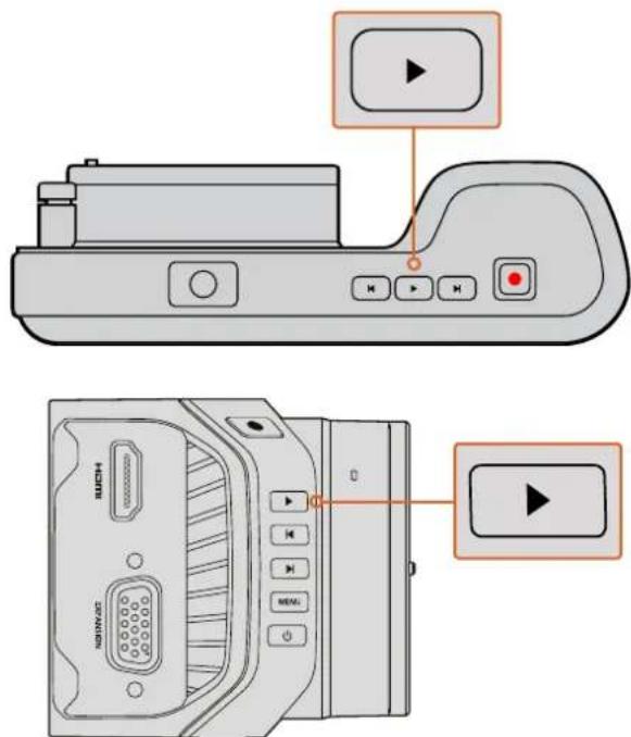
To immediately view your recorded clip on a Blackmagic Camera simply press the 'play' button on the transport controls
Camera Connections
Blackmagic Pocket Cinema Camera
natural_image
Line drawing of a black-and-white photo camera with lens and control buttons (no text or symbols)LANC Remote Control
The remote port on your camera is used to remotely control record starting and stopping, iris adjustments and manual focus adjustments when using a compatible lens.
The port is a 2.5 mm stereo jack using the standard LANC protocol.
Headphones
Monitor audio while recording or playing back clips by plugging your headphones into the 3.5mm stereo headphones jack.
Audio In
The 3.5mm stereo audio connector accepts microphone or line level audio. It's important to select the appropriate setting or your audio may sound too quiet or too loud. The camera automatically switches to line level if the audio is too loud for a sustained period.
HDMI Out
The micro HDMI port outputs 10-bit uncompressed HD1080p video, even while recording. It can be used to output video to routers, monitors, capture devices, broadcast switchers and other HDMI devices.
Power
Use the 0.7mm 12 – 20V power input for connecting your power supply and to charge the battery.
USB
Use the USB port to connect your Blackmagic Pocket Cinema Camera to your computer and update the internal software. The USB port can be found inside the battery compartment.
Blackmagic Micro Cinema Camera
natural_image
Line drawing of a digital camera module with control buttons and ports (no text or symbols)HDMI Out
The HDMI output supports 10-bit 4:2:2 1080p HD video with 2 channels of embedded audio. This gives you the option to either send a clean video feed or insert overlays on the HDMI output from the camera menu.
Expansion Port
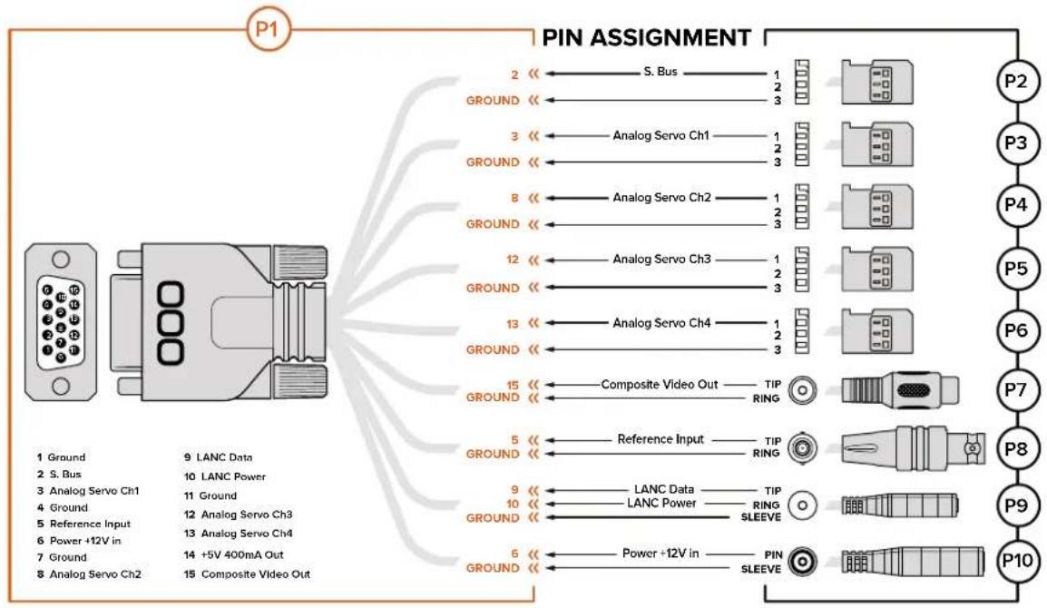
The expansion port is a standard DB-HD15 connector which includes connections such as +12v power, analog servo, BNC and RCA connectors. The DB-HD15 is actually quite an old fashioned connector and it was chosen because its extremely easy to solder wires to it and the plugs are very common so are easy to purchase. This means you don't have to use the included breakout cable as you can make up your own custom cables simply by soldering the wires you need to the relevant pins on the DB-HD15 plug. If you look closely at the pins you can see the pin numbers.
This makes it easy to look up the connector signal layout and connect the wires you need. You can add a backshell to the DB-HD15 on custom cables or you can even put a little silicon compound on the plug to keep it small when the camera is being used on a moving mount.
TIP For more information about the expansion port and expansion cable, refer to the 'Blackmagic Micro Cinema Camera Expansion Port and Expansion Cable' section on the following page.
Analog Audio In
The 3.5mm stereo audio connector accepts both microphone and line level audio, selectable in the camera menu. The microphone level audio is lower than the line level audio so if you are connecting a microphone to the camera and have the line level selected, you will find that the levels will be too low. You can also use the analog audio input for embedding timecode onto your video clip by sending an SMPTE compliant LTC timecode in the left audio channel and selecting the timecode option in the camera menu.
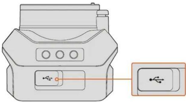
USB
Use the mini USB port to connect your Blackmagic Micro Cinema Camera to your computer for software updates. The USB port can be found on the bottom of the camera.
natural_image
Diagram of a device with a USB port and an icon showing a USB symbol (no text or labels present)The USB port is located on the bottom of the Micro Cinema Camera
Blackmagic Micro Cinema Camera Expansion Port and Expansion Cable
There are two ways to access the expansion port's functions. You can use the expansion cable that comes with your Micro Cinema Camera, or solder your own custom connectors.
Blackmagic Micro Cinema Camera has a standard DB-HD15 serial connector and can be used with the included expansion cable for the following control options:

flowchart
graph TD
    A["Port 1"] --> B["Port 2"]
    C["Port 3"] --> D["Port 4"]
    E["Port 5"] --> F["Port 6"]
    G["Port 7"] --> H["Port 8"]
    I["Port 9"] --> J["Port 10"]
    B --> K["Internal Connector"]
    D --> K
    F --> K
    H --> K
    J --> K
    style A fill:#f9f,stroke:#333
    style C fill:#f9f,stroke:#333
    style E fill:#f9f,stroke:#333
    style G fill:#f9f,stroke:#333
    style I fill:#f9f,stroke:#333
    style J fill:#f9f,stroke:#333
Blackmagic Micro Cinema Camera Expansion Cable
1 Power Input
The 12V power input connects via a DC jack and provides power to the Micro Cinema Camera, as well as trickle charging any batteries attached. When mains power is supplied, the camera will automatically turn on.
2 Reference Input
This allows multiple cameras to be genlocked to a blackburst or tri-level reference signal. Genlocking cameras to an external reference signal helps to prevent timing errors which may result in the picture jumping when switching between different cameras.
On the Blackmagic Micro Cinema Camera, the HDMI overlays will display 'REF' on screen when a valid reference source is detected, and the camera is locked to it.
3 LANC
Connect wired LANC remote controllers to the 2.5mm jack for controlling functions like recording start and stop, iris adjustment, and manual focus from a tripod arm when using compatible lenses. On some compatible lenses, you can also remotely control the zoom via LANC.
4 Composite Video Out
Standard definition composite video output via an RCA connector. You can connect this output to any low cost composite display device or even a wireless composite transmitter. The output can be selected to be either NTSC or PAL standard from the camera's menu.
5-8 Analog Servo Ch1 – Ch4
The four analog servo ports are connected with the Futaba J connectors to a compatible receiver unit. This is used to wirelessly control your camera. Each PWM analog input operates a single channel that can drive a feature such as lens focus, iris and servo zooms. You can also connect a simple switch so that you can quickly toggle the camera to start and stop recording. The camera will treat each of the analog channel as a switch until it detects a PWM signal. Once a PWM signal is detected, it will automatically latch on and respond to PWM signals. Power cycle the camera if you want to use a switch to control the camera.
9 S.Bus Digital Servo
By connecting to a compatible S.Bus receiver using the Futaba J cable, you have 17 S.Bus remote channels where features of the camera can be assigned to and remotely controlled. Channel 18 is reserved as a reset switch so that the camera can be reset to its default exposure settings. These features can include focus, servo zoom, iris control and other such features. For more information about mapping functions to S.Bus remote channels, see the 'Remote Settings' section of this manual.
Wiring Diagram for the Blackmagic Micro Cinema Camera Expansion Cable
flowchart
graph TD
    P1["Device"] -->|Pin Assignment| P2["Pin 2"]
    P1 -->|Pin Assignment| P3["Pin 3"]
    P1 -->|Pin Assignment| P4["Pin 4"]
    P1 -->|Pin Assignment| P5["Pin 5"]
    P1 -->|Pin Assignment| P6["Pin 6"]
    P1 -->|Pin Assignment| P7["Pin 7"]
    P1 -->|Pin Assignment| P8["Pin 8"]
    P1 -->|Pin Assignment| P9["Pin 9"]
    P1 -->|Pin Assignment| P10["Pin 10"]

    A["Pin 1: Ground"] --> B["Pin 2: S. Bus"]
    A --> C["Pin 3: Analog Servo Ch1"]
    A --> D["Pin 4: Ground"]
    A --> E["Pin 5: Reference Input"]
    A --> F["Pin 6: Power +12V in"]
    A --> G["Pin 7: Ground"]
    A --> H["Pin 8: Analog Servo Ch2"]

    I["Pin 2"] <--> J["S. Bus"]
    K["Pin 3"] <--> L["Analog Servo Ch1"]
    M["Pin 8"] <--> N["Analog Servo Ch2"]
    O["Pin 12"] <--> P["Analog Servo Ch3"]
    Q["Pin 13"] <--> R["Analog Servo Ch4"]
    S["Pin 15"] <--> T["Composite Video Out"]

    U["Pin 5"] <--> V["Reference Input"]
    W["Pin 9"] <--> X["LANC Data"]
    Y["Pin 10"] <--> Z["LANC Power"]
    AA["Pin 6"] <--> AB["SLEEVE"]

    AC["Pin 6"] <--> AD["Power +12V in"]
    AE["Pin 5"] <--> AF["SLEEVE"]
When using Blackmagic Micro Cinema Camera's expansion port, you may only want to access one or two functions. For example, you may want to use the composite video output feature while simultaneously controlling the zoom function. It's easy to make a connector that will give you just these functions without the clutter of additional, unused connectors.
Use the following diagram when wiring the expansion cable included or use it as an example of how you can wire up the connections on your own custom cable correctly. The full range of available pins are listed under group P1, while subsets used for particular functions, as well as their layout within the appropriate connectors, are shown in groups P2 through P10.
Tally Light Indicators
Blackmagic Micro Cinema Camera Tally Light
Blackmagic Micro Cinema Camera includes a tally light feature. The tally light indicates the following camera scenarios to the camera operator:
| White Power On | |
| Red Recording | |
| Green (flashes 3 times) SD card is being inserted and recognised | |
| Green SD card is present in the camera / camera is playing back. | |
| Red (flashing slowly) Card filling up | |
| Red (flashing quickly) Dropped Frames | |
| Red, Orange (alternating slowly) Battery low when recording | |
| White, Orange (alternating slowly) Battery low when in standby |
You can adjust the brightness of the tally light in Micro Cinema Camera's settings. See the 'camera settings' section for more information.

natural_image
Diagram of a camera with red highlighted lens and inset view showing internal components (no text or symbols)The tally light is located at the top of Blackmagic Micro Cinema Camera's lens
Menu Settings
Dashboard
The dashboard feature is opened by pressing the 'menu' button. From the dashboard you can access the 'settings' menu and key features such as metadata, media formatting, activating meters, frame guides and focus peaking. Press 'menu' again to exit the dashboard.
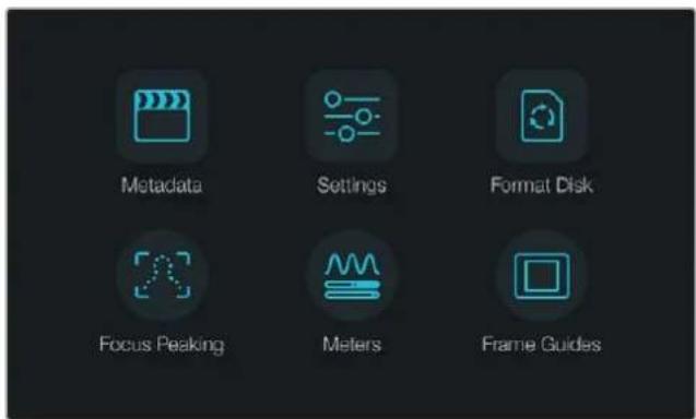
Press the 'menu' button to open the dashboard
To view menu settings on Blackmagic Micro Cinema Camera, simply connect an external monitor such as the Blackmagic Video Assist to the HDMI port or use the composite output on the expansion cable to connect to a low cost composite display. Pressing the 'menu' button brings you directly to the menu screen.
Camera Settings
To configure camera settings on your Blackmagic compact camera, press the 'menu' button to open the dashboard, select the 'settings' icon, then select the camera icon to the left of the settings menu. If you want to bypass the dashboard for direct access to the menu screen, simply hold down the menu button. Pressing the 'menu' button in Micro Cinema Camera opens the menu settings display.
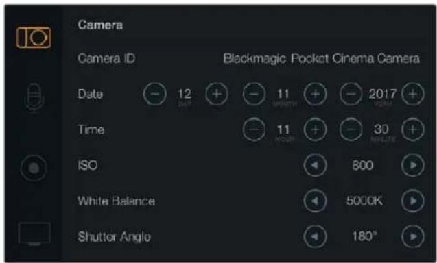
The 'camera' settings screen lets you adjust key features such as ISO, white balance, shutter angle, date, time and camera ID
Blackmagic Pocket Cinema Camera
Press the up and down buttons to highlight each settings menu. Press 'ok' to enter a settings menu. Use the left and right directional arrows to adjust values and the up and down arrows to move between settings. Press 'menu' again to return to selecting between main settings pages.
Blackmagic Micro Cinema Camera
Press the left and right arrow buttons to navigate and change settings. Press the 'play' button to highlight a setting and to confirm a change. Press the 'menu' button to return to the menu screen.
Camera ID
If using more than one Blackmagic Camera, it's helpful to set each camera's ID which will be included with any metadata recorded with your clips. Set the camera ID with the onscreen keyboard. When you have finished entering a new camera ID, select 'enter' to save, or select 'cancel' to discard any changes.
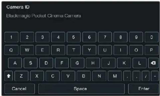
Change the camera ID using the onscreen keyboard
TIP The camera ID becomes part of the filename in the recorded file. Therefore if you would like to shorten the length of your filename, you may do so by shortening the camera ID. For example to 'BMPCC4'.
If you're using the Blackmagic Micro Cinema Camera, you will find the 'camera number', 'date' and 'time' settings in the 'setup' menu.
Setting Date and Time
To set date and time on your Blackmagic Pocket Cinema Camera, select the + or - buttons to change the year, month and day settings.
Time is set to 24 hour format on Blackmagic Cameras. To set the time, select the + and - keys to make adjustments to the time. If traveling with your Blackmagic Camera, remember to change the date and time to local time zones.
TIP If you have your Blackmagic compact camera stored for long periods, the time may need to be reset. It is always a good idea to check the time and date prior to recording. When connecting your camera to your computer via USB and launching Blackmagic Camera Setup, your computer's time is synced to your camera.
ISO
ISO settings are helpful when you are shooting in a variety of light conditions.
The optimum ISO setting for your Blackmagic compact camera is 800, with a maximum setting of 1600.
Depending on your shooting conditions, you may choose a lower or higher ISO setting.
For example, in low light conditions 1600 would be suitable, but may introduce some visible noise. In bright conditions 400, or 200 would be best to record richer colors.
Adjust the ISO settings using the arrow icons in the menu.
White Balance
Your Blackmagic compact camera includes white balance presets for a variety of color temperature conditions. Each light source emits a warm or cool color. Warm appears red and cool appears blue, so the white balance setting adds opposing red or blue to compensate.
This makes sure white stays white in your image.
Color temperature also changes depending on the position of the sun and the cloud conditions.
For example, light is warm at sunrise, cools down until midday, then warms up again as the sun sets. Shady areas in your picture, including overcast conditions, will generally appear blue.
Use the following guide to set your white balance to compensate for the changing light conditions:
- 2500, 2800, 3000, 3200, 3400, 3600, 4000, 4500 and 4800K for various conditions under tungsten, incandescent or fluorescent light, or under dull natural light including candle light, sunrise/sunset, morning, and after noon light.
- 5000, 5200, 5400 and 5600K for outdoors on a clear, sunny day.
- 6000, 6500, 7000, 7500 and 8000K for a variety of daylight conditions.
Adjust the white balance settings using the arrow icons in the menu.
Shutter Angle
Shutter angle complements the ISO setting by regulating the amount of light on the sensor. 180 degrees is the optimum shutter angle, however as lighting conditions change you may need to adjust accordingly. For example, 360 degrees is considered 'wide open' and allows maximum light onto the sensor. This is useful for low light conditions. If you notice lights are flickering, 172.8 degrees will minimize this effect when shooting 24p in countries with 50 hertz power supplies.
Adjust the 'shutter angle' settings using the arrow icons in the menu.
Auto Exposure
Blackmagic Micro Cinema Camera has the following auto exposure options.
Iris
Maintains a constant shutter speed while changing the aperture to achieve a constant exposure.
Shutter
Maintains a constant aperture while changing the shutter speed to achieve a constant exposure.
Iris + Shutter
Maintains a constant exposure level by adjusting the aperture. If the maximum or minimum available aperture is reached and exposure still cannot be maintained, Micro Cinema Camera will begin adjusting the shutter speed to keep exposure constant.
Shutter + Iris
Maintains the correct exposure levels by adjusting the shutter speed. If the maximum or minimum available shutter speed is reached and exposure still cannot be maintained, Micro Cinema Camera will begin adjusting the aperture to keep exposure constant.
Manual Trigger
Iris aperture and shutter speed are set manually and exposure may vary with changing light conditions.
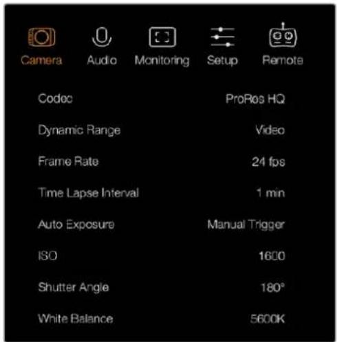
The 'camera' settings screen in Blackmagic Micro Cinema Camera
Audio Settings
To adjust audio input and audio monitoring settings on your Blackmagic Pocket Cinema Camera, press the 'menu' button to open the dashboard, select the 'settings' icon, then select the microphone icon to the left of the settings menu.
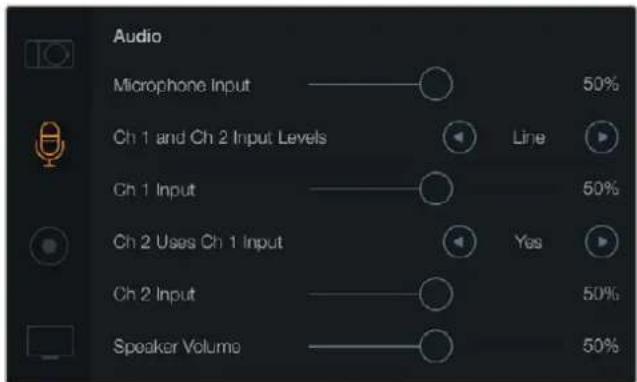
The 'audio' settings screen lets you adjust the microphone input level, input level type, audio channel levels, mirror ch 1 audio to ch 2, and adjust the headphones or speaker volume
On Blackmagic Micro Cinema Camera, press the 'menu' button to enter the menu settings display. Use the left and right arrow buttons to move and select 'audio', then press the 'play' button to confirm your selection.
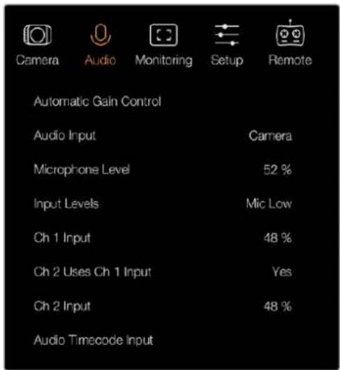
The 'audio' settings on Blackmagic Micro Cinema Camera
Microphone Input
Microphone input adjusts the recording levels of the built in microphone. Move the audio slider left or right to increase or decrease levels. Blackmagic Micro Cinema Camera and Blackmagic Pocket Cinema Camera have built in stereo microphones that record to audio channels 1 and 2 when no external audio source is connected.
Input Levels
External audio connectors accept audio at microphone level or line level. It's important to select 'mic' or 'line' level audio as appropriate to avoid your external audio sounding almost inaudible or too hot and distorted.
Set the external audio input levels by using the left and right arrow buttons on your camera.
Channel 1 Input
To increase or decrease levels for channel 1, move the audio slider icon left or right. If you're using the Micro Cinema Camera, use the left and right arrow buttons on the camera. The external audio input overrides the built in microphone and is recorded to audio channel 1.
Channel 2 uses Channel 1 Input
Select 'yes' if you only have channel 1 input and want to record the same external audio to channels 1 and 2. You can leave this set to 'no' if you only want to record one channel of audio.
Channel 2 Input
To increase or decrease levels for channel 2, move the audio slider icon left or right. If you're using the Micro Cinema Camera, use the left and right arrow buttons on the camera. The external audio input overrides the built in microphone and is recorded to audio channel 2.
Headphone and Speaker Volume
When headphones are connected, a headphone icon will be displayed. When no headphones are detected, a speaker icon will be displayed. Headphones will always be active when recording or playing back, however speakers will only work when playing back. Move the volume slider left or right to increase or decrease audio monitoring levels.
Audio Input
Select if your audio input is from the 'camera' or from an external audio 'input' such as a microphone.
Automatic Gain Control
Setting the automatic gain control to 'on' will allow your Blackmagic Micro Cinema Camera to automatically adjust the audio input levels during recording. The gain control will automatically increase or decrease the recording level depending on the strength of the sound in your environment. This is useful in environments where sound levels can be unpredictably loud or quiet. For example, loud unpredictable bursts and moments of quiet during a fireworks display or a live performance.
Audio Timecode Input
Select 'on' if you want to embed LTC timecode via the 'mic' input into your recording on Blackmagic Micro Cinema Camera. Having embedded timecode is useful for syncing multiple clips during post production. For example, when using the multi camera editing feature in DaVinci Resolve 14 or newer.
Recording Settings
The recording settings are used to set the video format recorded to your SD card. Press the 'menu' button to open the dashboard, select the settings icon, then select the circular record icon to the left of the settings menu.
On Blackmagic Micro Cinema Camera, you will find recording settings under the 'camera' settings. Press the 'menu' button to enter the menu settings display. Use the left and right arrow buttons to move and select 'camera', then press the 'play' button to confirm your selection.
Recording Format
Blackmagic Pocket Cinema Camera
Press the left and right arrow buttons to switch between ProRes HQ, ProRes 422, ProRes LT, ProRes Proxy or RAW recording formats.
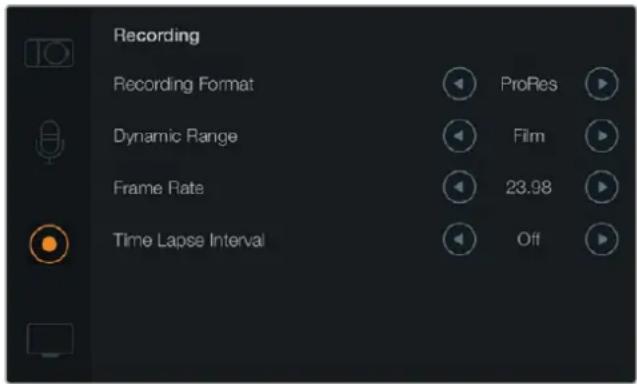
The ‘recording’ settings screen on Blackmagic Pocket Cinema Camera
Blackmagic Micro Cinema Camera
Press the left and right arrow buttons to switch between ProRes HQ, ProRes 422, ProRes LT, ProRes Proxy, RAW or RAW 3:1 recording formats.

On Blackmagic Micro Cinema Camera the 'recording' settings are located in the 'camera' settings
Dynamic Range
Blackmagic Cameras have two dynamic range settings:
Film
The film setting records video using a log curve and gives you 13 stops of dynamic range, which maximizes the information in your video signal to help you get the most out of color grading software, such as DaVinci Resolve. When recording in CinemaDNG RAW formats, only the film dynamic range setting is available.
Video
The video setting uses the REC709 standard for high definition video. This lets you work faster by recording directly to the compressed video formats your camera supports, which are compatible with popular post production software. Adjust the dynamic range settings using the arrow icons in the menu.
Frame Rate
Your Blackmagic compact camera has five different frame rate settings for shooting common film and video frame rates, including 23.98 fps, 24 fps, 25 fps, 29.97 fps, 30 fps. Blackmagic Micro Cinema Camera also includes frame rates up to 50 fps, 59.94 fps and 60 fps.
Adjust the frame rate setting using the arrow icons in the menu, or the left and right arrow buttons on Blackmagic Micro Cinema Camera.
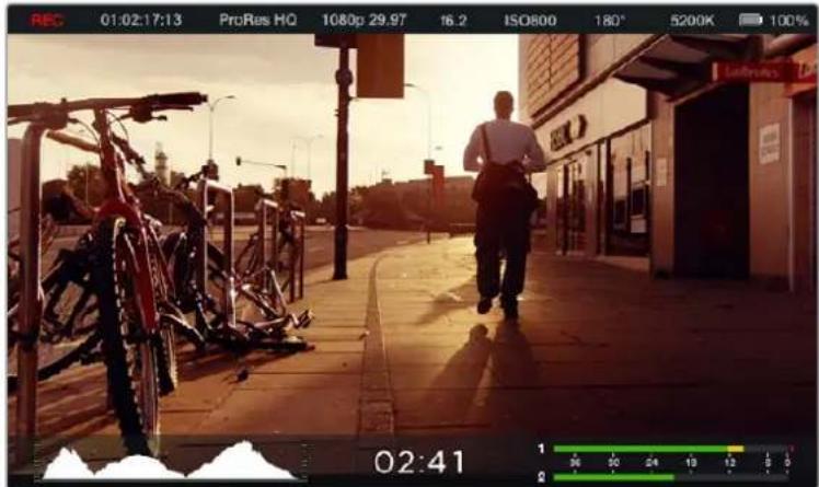
Time Lapse Interval
This setting allows you to record a still frame at the following intervals:
Frames: 2 - 10
Seconds: 1 – 10, 20, 30, 40, 50
Minutes: 1 – 10
For example, you can set the camera to record a still frame every 10 frames, 5 seconds, 30 seconds, 5 minutes etc.
The time lapse feature offers many creative options. For example, if the time lapse interval is set to record a frame at 2 frame intervals, this will give your recorded video a high speed effect when played back.
The format of each still frame is based on your recording format, so if you set the camera to record in ProRes 422 HQ, the time lapse setting will maintain this format. The frame rate will be based on the video frame rate you have set the camera to, i.e., 24fps, so your time lapse footage can be incorporated into your workflow easily.
When the 'rec' button is pressed in time lapse mode, the 'time lapse record' icon will replace the standard record icon. The timecode counter updates when a frame of video is recorded, meaning the rate of timecode increments depends on the time lapse interval setting.
| 00:00:05:15 | 2.5K RAW | 1350p24 | f6.2 | ISO800 | 180° | 5200K | 100% |
Use the arrow icons to choose a time lapse interval or leave it set to 'off' if you do not want to use the time lapse feature.
File Naming Convention
Blackmagic Pocket Cinema Camera uses the following file naming convention when recording video.
[Camera ID]_[Reel Number]_[yyyy-mm--dd]_[hhmm]_C[Clip number].mov
Blackmagic Micro Cinema Camera uses the following file naming convention.
[Camera ID]_[yyyy-mm-dd][hhmm]_C[Clip number].mov
The table below shows an example of the file naming convention.
| BMC01_1_2017-08-08_1631_C0002.mov QuickTime Movie Filename | |
| BMC01_1_2017-08-08_1631_C0002.mov Camera ID | |
| BMC01_1_2017-08-08_1631_C0002.mov | Reel Number |
| BMC01_1_2017-08-08_1631_C0002.mov | Date (2017 Aug 08) |
| BMC01_1_2017-08-08_1631_C0002.mov | Time (16:31pm - 24hrs) |
| BMC01_1_2017-08-08_1631_C0002.mov | Clip Number |
Display Settings
To adjust the display settings for the LCD and HDMI output, press the 'menu' button to open the dashboard, select the 'settings' icon, then select the television icon to the left of the settings menu.
You will find display settings under the 'monitoring' section on Blackmagic Micro Cinema Camera. Press the 'menu' button to enter the menu settings display. Use the left and right arrow buttons to move and select 'monitoring', then press the 'play' button to confirm your selection.
Dynamic Range
The LCD allows you to view your video as you are recording. You can set the dynamic range of the LCD by selecting 'video' or 'film'.
The dynamic range setting of the LCD is independent to the dynamic range set in the recorder settings. Some people prefer to monitor video with the LCD set to 'video' even when the recording format is set to 'film'.
Adjust the dynamic range setting of the LCD using the arrow icons in the menu.
Brightness
On Blackmagic Pocket Cinema Camera, move the slider icon left or right to adjust brightness settings for the LCD.
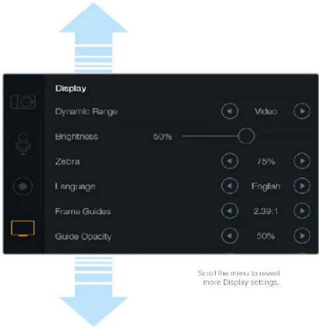
Display settings on Blackmagic Pocket Cinema Camera lets you set the brightness of the LCD, turn LCD overlays on or off, adjust the display dynamic range and zebra settings. You can also choose what overlays are visible on your camera's HDMI output and select your desired frame guides.
Tally Light Brightness
Changes the brightness of the Tally Light on Micro Cinema Camera. Settings include: low, medium and high. The default setting is medium. You can also set the Tally Light to 'off'.
Zebra
The zebra feature helps you achieve optimum exposure by displaying diagonal lines over areas of the video that exceed your set zebra level. Turn the zebra feature on or off and adjust the 'zebra level' by tapping the left and right arrow icons. Setting the zebra to 100% shows which areas are clipped.
Language
The Blackmagic Pocket Cinema Camera menu can be set to display various languages.
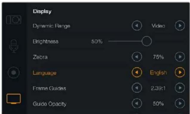
Blackmagic Pocket Cinema Camera lets you change the 'language' setting so you can view the menu in various languages
To set the language:
1 Press the 'menu' button to open the dashboard on the LCD. You can also bypass the dashboard by pressing and holding the 'menu' button. Select 'settings' using the navigation buttons and press 'ok'.
2 Navigate to the 'display' settings and select 'language'.
3 Cycle through the different languages by pressing the right and left navigation buttons and press 'ok' to confirm. You can also confirm your language setting by pressing the 'menu' button. It may take a second to two for the display to update.
HDMI Overlays
You can monitor your video on an external display using the HDMI output on your camera.
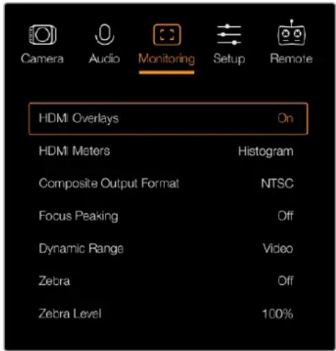
Set the HDMI overlays to 'on' or 'off' in Blackmagic Micro Cinema Camera
The 'HDMI overlay' setting lets you display useful information on your monitor. On Blackmagic Pocket Cinema Camera, use the arrow icons to select which overlays to display on your HDMI feed.
All: displays both frame guides and recording information.
Status: displays only the recording information, such as f-stop number, frame rate, battery life etc.
Guides: displays only the frame guides.
Off: gives you a clean feed.
On Blackmagic Micro Cinema Camera, you can set HDMI overlays to 'on' or 'off'. Use the left and right arrow buttons to select, then press the 'play' button to confirm your selection.
LCD Overlay
On Blackmagic Pocket Cinema Camera, you can turn the frame guides on or off for the LCD independently of the HDMI output. For example, you may want to view frame guides on the LCD, but output a clean video feed over the camera's HDMI output.
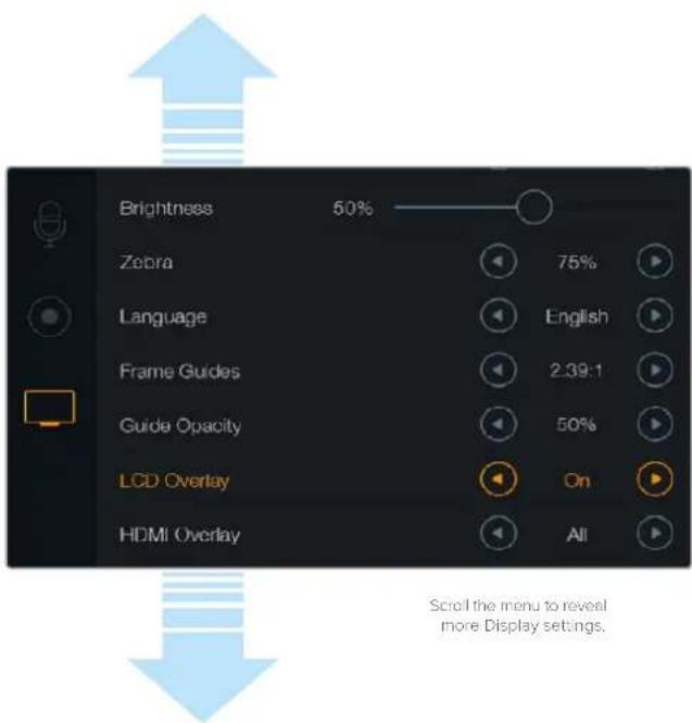
The frame guides setting on Blackmagic Pocket Cinema Camera lets you display overlays on the camera's LCD and HDMI output
Frame Guides
On Blackmagic Pocket Cinema Camera, you can choose from several different frame guides to display on the LCD screen and HDMI output. On Blackmagic Micro Cinema Camera, frame guides can be viewed on the HDMI output or the composite output. Frame guides include aspect ratios for various cinema, television and online standards, plus a rule of thirds composition grid. Use the 'frame guides' setting arrow icons to select your desired frame guide. Frame guide settings can be found under the 'monitoring' section.
HDTV: Displays action and title safe regions of your image within a 1.78:1 aspect ratio compatible with 16:9 HD television and computer screens.
4:3: Displays the 4:3 aspect ratio compatible with SD television screens, or to help frame shots when using 2x anamorphic adapters.
2.35:1, 2.39:1 and 2.40:1: Displays the broad widescreen aspect ratio compatible with anamorphic or flat widescreen cinema presentation. The three widescreen settings differ slightly based on the changing cinema standards over time. 2.39:1 is one of the most prominent standards in use today.
1.85:1: Displays another common flat widescreen cinema aspect ratio. This ratio is slightly wider than HDTV 1.78:1 but not as wide as 2.39:1.
Thirds: Displays a grid with two vertical and horizontal lines placed in each third of the image. Thirds are an extremely powerful tool to help compose your shots. For example, the human eye typically looks for action near the points where the lines intersect, so it's helpful to frame key points of interest in these zones. An actor's eyeline is commonly framed along the top third of the screen, so you can use the top horizontal third to guide your framing. Thirds are also useful to maintain framing consistency between shots.
Guide Opacity: Aspect ratios are displayed as mattes on the top and bottom of your LCD display. You can adjust the opacity of the matte by adjusting the 'guide opacity' setting. For example, if you prefer to view your guides as solid mattes, select 100%. Alternatively, if you would like to view guides at maximum transparency, set the guide opacity to 25%.
Frame guides provide helpful markers so you can accurately compose your shots for various television, online and cinema aspect ratios, for example the popular 2.39:1 flat widescreen ratio as shown above.
Remote Settings
Blackmagic Micro Cinema Camera features a 'remote' settings menu, which is used to configure the PWM and S.Bus channels connected to the expansion port.
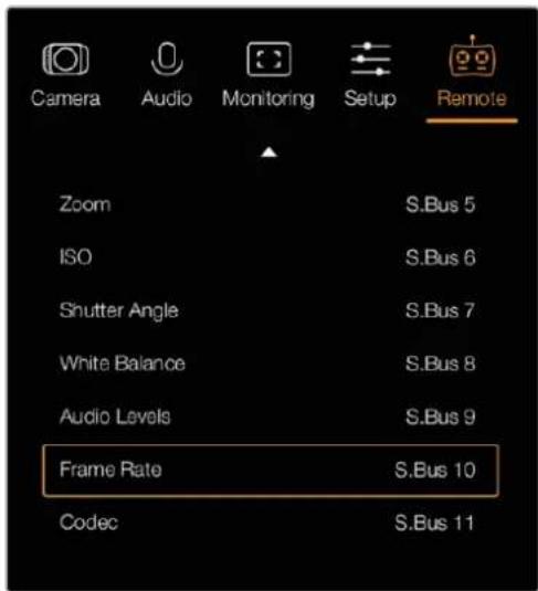
Remote Settings menu on Micro Cinema Camera
PWM
Analog radio control transmitters and receivers are typically used to drive servos on model airplanes, but can also be used for wireless remote control of the Blackmagic Micro Cinema Camera.
The 4 analog PWM radio remote control inputs on the expansion cable allow you to map camera functions to the controls on model airplane controllers. The dials, switches and joysticks on the radio controller are output on different radio channels and these channels can be assigned to four different camera functions in the remote settings menu. This provides you with a low cost, power efficient way to wirelessly control your camera. You can even generate your own PWM signals from your own Arduino or Raspberry Pi projects to control the camera.
S.Bus
If you need more than 4 channels you can use the 18 channel S.Bus control input with Futaba radio control equipment or custom embedded controllers.
The S.Bus protocol uses 1 connection on the expansion cable to control up to 18 channels, and each of these channels can be mapped to a specific camera function. Most often used for radio remote control of airplane and helicopter models, S.Bus receivers and decoders can be found in most major hobby stores online.
Assigning Camera Functions to S.Bus Channels
If you are using S.Bus to control your Micro Cinema Camera, you can use the 'remote' menu to assign the following functions to individual S.Bus channels:
- Rec start/stop
- Iris
- Focus
- Auto focus
- Zoom
ISO - Shutter angle
- White balance
- Audio levels
- Frame rate
- Codec
To assign functions to individual S.Bus channels, simply select the function you wish to control and assign an available channel using the 'left' and 'right' buttons, and use the 'play' button to confirm.
Standard radio transmitters for remote control vehicles that support the S.Bus protocol are usually setup with control ranges built into their controller output, so that all you need to do is assign camera functions to the correct individual S.Bus channels for remote control of your camera functions. You can also use the S.Bus protocol to develop your own sophisticated custom control solutions.
Developing a Custom Controller
If you would like to develop your own custom camera control solutions, you can use the S.Bus input on the expansion cable as a way to interface camera functions on Blackmagic Micro Cinema Camera.
When sending commands via the S.Bus input to Blackmagic Micro Cinema Camera, the input values will need to be between 44 and 212 in order to be interpreted by the camera. A value of 128 is considered to be the midpoint or neutral position when using a radio control transmitter.
The way in which specific commands are sent to the camera will depend upon how you have mapped the camera functions to your controller.
There are two ways to map the commands to the controls.
The first type maps settings to specific ranges of the input so that sending a value within a certain range will trigger a particular setting.
For example, the f-stop settings on a lens from f1.8 to f22 will be distributed along the entire range of 44 to 212. Sending a value between 44 and 51 would set the lens to f1.8. These values will then continue along the entire range so that sending a value between 206 and 212 would select f22. Zoom and focus changes are controlled the same way.
The second type of control registers any change from the neutral value of 128 to a value above or below and then back to the neutral point. This will be considered by the camera as a valid toggle signal, which increases or decreases the assigned settings. Settings like the REC trigger, autofocus, gain, shutter angle, white balance and frame rate work on this basis.
You could assign camera functions to a control like a spring loaded joystick which snaps back to a neutral center point after each movement up or down. In this example a value of 44 would represent the maximum downward position of the joystick and 212 would represent the maximum upward position, while the center functions as a neutral point with a value of 128.
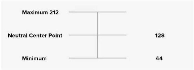
bar
| Category | Value | |---|---| | Maximum 212 | | | Neutral Center Point | 128 | | Minimum | 44 |For example, if your gain settings are mapped to a joystick in this way, then after each upward movement of the joystick it would return to the neutral point in the center which toggles the camera to increase gain by one increment, say from 0dB to 6dB.
You could also send this same information in numerical form to another type of controller that uses numerical values. In this case you would send a value of 128, followed by a value above 128 such as 212, and then back to 128 again. The camera will register this as an increment command and change the gain from 0dB to 6dB.
The way in which you assign commands will depend upon the kind of control system that you are using to control your camera and the type of control that you want to assign. Spring loaded controls that snap back to a neutral point are very common on radio control transmitters for model aircraft and drones.
If you are using a Futaba style remote control, some functions will be more suited to the rotating dials or analogue sticks, whilst other functions will be more suited to the switches.
TIP See the 'Blackmagic Micro Cinema Camera Expansion Port and Expansion Cable' section for more information about the expansion port and its specific connections.
On Screen Meters
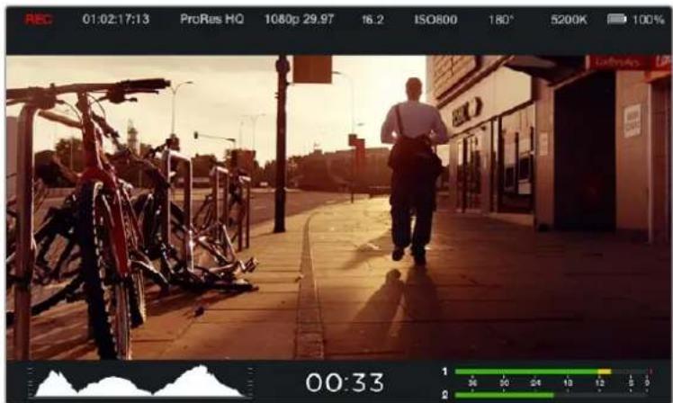
Your Blackmagic Camera features meters such as recording time remaining, histogram and peak audio to assist when setting optimum exposure, checking how much space is left on your media, and to prevent your audio from clipping.
On screen meters can also be opened or hidden by selecting or deselecting the 'meters' feature on the dashboard.
On Blackmagic Micro Cinema Camera, HDMI meters can be found under the 'monitoring' section. Use the left and right arrow buttons to move and select your desired meters, then press the 'play' button to confirm your selection.
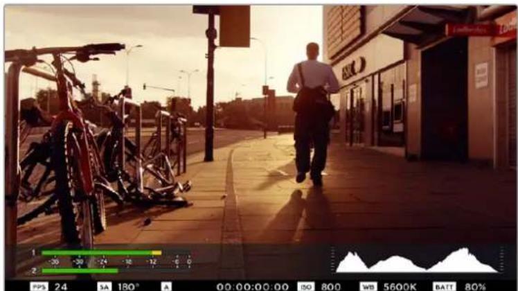
On screen meters and status strip on the Blackmagic Micro Cinema Camera
Histogram
The histogram display shows the distribution of the luminance in your video. Pure black is on the far left side of the display and pure white is on the far right of the display. Keeping your video signal within these limits prevents your shadows and highlights from being clipped and preserves detail in the tonal ranges.
Recording Time Remaining
The recording time remaining indicator shows the remaining recording time for your SD card. The time is shown in hours and minutes and will vary according to your selected frame rate and codec. For example, ProRes 422 HQ at 24 frames per second. The indicator will automatically recalculate if either of these settings are changed. When there is approximately 5 minutes remaining on your SD card the indicator will turn red, and will blink intermittently when there is only 2 minutes remaining.
Peak Audio
The peak audio meters display audio levels for channels 1 and 2 when using the internal microphone, or via external audio when connected. The display is calibrated to dBFS units and features peak hold indicators which stay visible for a short time so you can clearly see the maximum levels reached. To achieve optimum audio quality, adjust your audio levels until the peak averages at -12dB. If the audio level reaches 0dB the peak hold indicators will turn red, indicating that the audio signal is being clipped.
natural_image
Street scene with a person walking past parked bicycles under a bright sky (no visible text or symbols)On Blackmagic Micro Cinema Camera, the status strip and on screen meters can be viewed on the HDMI or composite output display
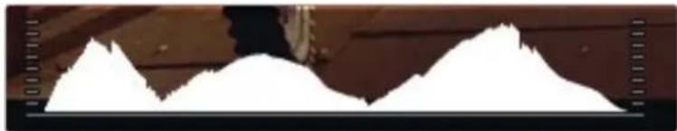
natural_image
Silhouette of two mountain peaks against a wooden wall background (no text or symbols)For optimum exposure, open or close your aperture until the histogram curve sharpens to a point at the bottom edges. A flat vertical edge on the sides of the histogram means your blacks or whites are clipped.
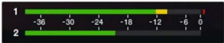
bar
| Category | Value | |---|---| | 1 | -36 | | 2 | -30 | | 2 | -24 | | 2 | -18 | | 2 | -12 | | 2 | -6 | | 2 | 0 |For optimum audio quality, adjust your audio levels until the peak averages at -12dB
Adjusting Settings
Blackmagic Pocket Cinema Camera supports electronic lens control, which allows you to adjust lens controls from the camera such as aperture and auto focus. The focus peaking feature creates a green edge around the sharpest parts of the image so you can easily confirm your focus. Focus peaking is visible on the LCD and via HDMI out with overlays set to 'on', but does not affect your recorded picture.
Iris Button
When using 'video' dynamic range settings, a single press of the 'iris' button will set an average exposure based on the highlights and shadows in your shot. When using film dynamic range settings, pressing the 'iris' button sets your exposure to the brightest highlight in your shot.
On Blackmagic Micro Cinema Camera, you can adjust your lens aperture manually by pressing the forward or reverse transport control buttons. To adjust your aperture on Blackmagic Pocket Cinema Camera, press the left and right directional buttons on the back panel.
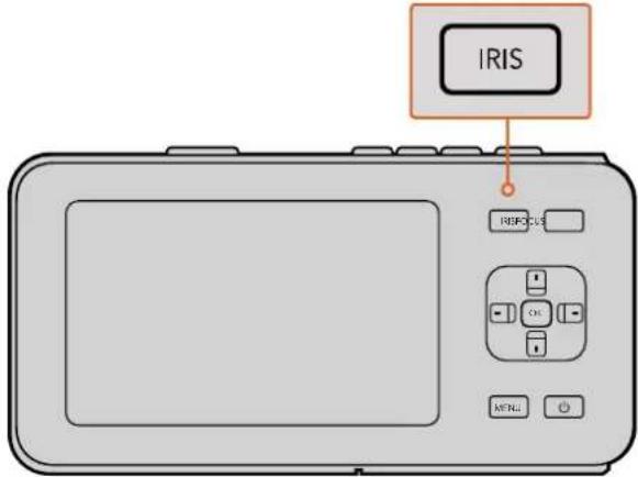
On Blackmagic Pocket Cinema Camera, press the 'iris' button, then use the left and right directional buttons to adjust aperture control
NOTE It's important to know that while most lenses support electronic focus, some lenses can be set to manual or auto focus modes, and so you need to ensure your lens is set to auto focus mode.
Focus Button
When using a compatible auto focus lens with Blackmagic Pocket Cinema Camera or EF mount Blackmagic cameras, press the 'focus' button once to auto focus. A quick double press of the focus button activates focus peaking.
When using a manual lens, press the focus button once for focus peaking.
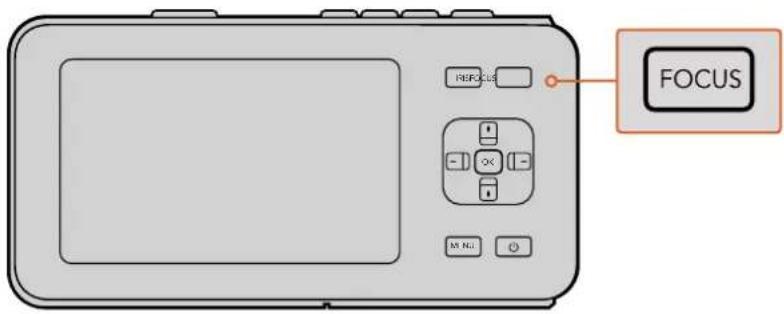
Press the 'focus' button for focus peaking
Focus Zoom
When using Blackmagic Pocket Cinema Camera, double press 'ok' to zoom in for adjusting focus at the 1:1 pixel scale. Double press 'ok' again to zoom out.
Image Stabilizer
Blackmagic Pocket Cinema Camera and Micro Cinema Camera support the image stabilizer (IS) feature found in many active lenses. Simply set the stabilizer switch to 'on' to use it with your camera. If your lens also features a stabilizer mode switch, set it to the appropriate mode for still shots or for movement.
TIP When using battery power, the camera will only activate the image stabilizer while recording, as the lens draws additional power from the camera to operate the image stabilizer. When external power is connected to the camera, the image stabilizer will be active any time you set the lens stabilizer switch to 'on'.
Status Strip
Your chosen settings are always displayed on a status strip, which runs the length of the LCD, HDMI or composite display, showing a convenient summary of the camera's current settings.

Battery Life Indicator
When the remaining charge drops below 25% capacity, the status strip will show the battery status in red to warn you that battery life is running low.
SD Activity Icons
The status strip displays important information showing the state of the inserted media.
Moving Dots When you see the moving dots, the camera is checking and preparing the media.
No Card This means no media is detected or present in the camera.
Ready Ready to record.
Red Icon Recording.
Flashing Red Icon Dropped frames were detected.
Card Full Appears when SD card is full.
Playback mode Displays play, fast forward and reverse icons.
Timecode Displays the duration of clips during recording and playback from your SD card.
Additionally, the following information is displayed along the bottom of the screen.
Histogram If this setting is enabled in 'main' menu, the histogram shows the distribution of luminance in your video
Time remaining Displays the remaining recording time available with the current settings.
Audio meters If this setting is enabled in the 'monitoring' menu, the peak audio meters display peak audio levels.

1 Media and Recording Status
2 Timecode
3 Recording Format
4 Video Format/Frame Rate
5 F-Stop
6 ISO Setting
7 Shutter Angle
8 White Balance
9 Battery Life Indicator
10 Histogram
11 Time remaining
12 Audio meters
Entering Metadata
What is the Slate?
On Blackmagic Pocket Cinema Camera, the slate feature allows you to easily log metadata directly into the camera. Metadata is stored in the recorded files and is easily accessed by editing software.
To use the slate:
1 Press 'ok' once to make the slate appear, or press the 'menu' button to open the dashboard and select 'metadata'.
2 Use the directional buttons to select the text you wish to change and press 'ok'.
An onscreen keyboard will appear. Use the directional buttons to select characters on the keyboard and press 'ok' to confirm each character selection.
3 Once you have entered your information, select 'save' and press 'ok' to return to the metadata screen.
4 If you want the scene, shot or take number to auto-increment, select the corresponding auto-increment icon so it is illuminated and press 'ok'.
Entering words into the 'keywords' field allows them to be used as search terms in your library database. This may be particularly useful for large projects with lots of material. The use of keywords narrows down the number of clips to search through, saving valuable time when you are editing.
All metadata is compatible with popular software such as Final Cut Pro X and DaVinci Resolve.
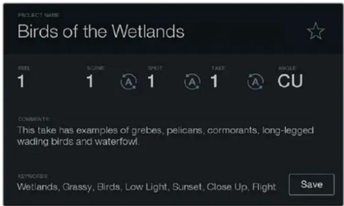
The 'slate' feature lets you include metadata information in your clip files for post production
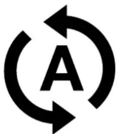
natural_image
Abstract circular arrow symbol with the letter 'A' at center, no text or numbers presentSelect the auto-increment icon if you want the scene, shot or take number to auto increment.
Using DaVinci Resolve
Shooting with your Blackmagic Design camera is only part of the process of creating film and television content, and just as important is the process of media backup and management as well as editing, color correction and encoding final master files. Your Blackmagic compact camera includes a version of DaVinci Resolve, both for Mac OS X and Windows. With DaVinci Resolve you have a complete solution for shooting and post-production!
NOTE We recommend using the latest version of DaVinci Resolve for accurate color treatment of clips shot using Blackmagic Design cameras. For example, version 14 or later will ensure accurate color for all Blackmagic Design cameras.
After connecting your SD Card to your computer, you can use DaVinci Resolve's 'clone' tool, in the 'media' page, to create running backups as you shoot. This is recommended as any type of media is susceptible to becoming damaged or developing a fault so creating backups ensures your shots will be immune to loss. Once you have used DaVinci Resolve to back up your media, you can then add your clips to the DaVinci media pool, then edit, color correct, and finish your production without ever having to leave DaVinci Resolve.
DaVinci Resolve is the same tool used on most major blockbuster movies, so it's much more than a simple NLE software tool, as it has extremely advanced technology built in for high end digital film. You get the advantage of this technology when you use DaVinci Resolve to edit and color correct your work.
Included here is information on how to get started using DaVinci Resolve with your camera files. Of course, DaVinci Resolve is extremely advanced and includes a lot more features than you immediately see when first looking at its user interface. To learn more about how to use DaVinci Resolve, please check for the DaVinci Resolve instruction manual pdf file on the DaVinci Resolve software disk, or check online for the many training courses and tutorial videos available.
Importing your Clips
To start editing your clips, you'll first need to import them into the media pool:
1 Launch DaVinci Resolve. If this is the first time you've opened DaVinci Resolve, wait for the Project Manager to appear, and double click the 'untitled project' icon in the project manager window.
If you have enabled the multi-user environment in previous versions of DaVinci Resolve, then the log in window will appear. To login as one of the listed users, double click the user icon. To add a new user, click 'add new' at the bottom left of the log in window and create a new user by entering a user name and clicking 'setup new user'.
Then double-click the user icon to proceed to the Project Manager. Now click 'new project', enter a title for your project and click 'create'. This will add your new project to the project manager. Double click on your project to open it.
2 You'll now see the 'media' page with a 'media storage' browser at the top left.
The 'media storage' browser displays all your linked media folders from where you'll drag your clips and drop them into the media pool.
3 If your clip folder doesn't appear in the library, you'll need to add it. This is easily done by right clicking inside the 'media storage' browser area, selecting a drive or folder path and clicking 'open'.
4 In the 'media storage' browser, click on your newly added clip folder. Now simply drag your clips from your storage folder and drop them into the media pool. If the untitled project settings are different to your clip settings, you'll be prompted to either change the project settings to match your clips, or leave the settings as they are. To get started quickly, click 'change'. Now your project settings match your clips.
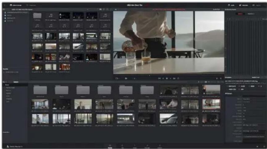
To import your clips, simply drag them from the 'media storage' browser and drop them into the media pool. You can also drag and drop files from your desktop
Working with RAW files
When you first import RAW files, DaVinci Resolve will decode the sensor data contained in the files using the ISO, white balance and tint settings used on the camera at the time of shooting. If you're happy with the look of these settings, you can start editing right away.
The great thing about shooting RAW is that you're not tied to these settings at all!
The breadth of available post processing options when working with RAW files mean that you'll develop your own workflow over time. Experimenting with the 'clip RAW' settings for each clip will show you just how powerful and flexible working with RAW can be.
RAW clips give you maximum flexibility in post production. While ProRes files, for example, convert your camera's sensor data into their respective codecs, RAW clips keep the original sensor data without conversion. This lets you make adjustments to clips, such as white balance and ISO settings, as if you were changing the original camera settings. Working with the original sensor data also retains more tonal information within shadows and highlights, which is useful for recovering details, for example in blown out skies and dark areas of the picture.
It's worth shooting in RAW if you are after the highest possible quality, or for shots where there is an extreme variance between highlights and shadows and you may need to push and pull those regions as much as possible in the grade.
RAW files can be large and processor intensive, but you can set DaVinci to automatically create proxy files to help your computer with real time playback. For more details on how to get the most out of your RAW files in your grade and how to set up a real time workflow, refer to the DaVinci Resolve manual.
Clip RAW Settings
Once your RAW clips are loaded into the media pool, you can drop them on a timeline in the edit page and then make adjustments to each clip in the color page.
To make individual adjustments to RAW settings on a per clip basis:
1 Open the 'edit' page, then drag and drop your selected clips into a new timeline.
2 Open the color page and click on the camera icon to open the 'camera raw' palette.
3 Select 'clip' from the 'decode using' dropdown menu.
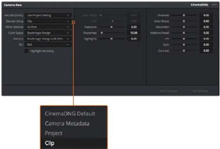
Select 'clip' from the 'decode using' drop down menu, to make adjustments to RAW settings for individual clips
Project RAW Settings
If you need to make a setting change that is common to all the clips, for example a global change to the white balance or ISO setting, you can set the clips to use the project RAW settings and make global changes from there.
To set project RAW settings:
1 Enter the project settings menu by clicking 'file,' and selecting 'project settings.'
2 In the 'Camera RAW' tab, you'll see a small arrow in the top right corner with one of several RAW formats next to it. This should be set to CinemaDNG. When you first drop a RAW clip shot on your Blackmagic Design camera into a new timeline, this setting will be set to CinemaDNG automatically.
3 Select 'project' in the 'Decode Using' drop down menu.
4 Set the white balance setting to 'custom'.
5 Set the color space to 'Blackmagic Design'. This will also set the gamma setting to Blackmagic Design Film.
Now you can adjust the camera settings for your clips such as white balance, ISO, sharpening, and more. This will affect all clips on your timeline.
For a full description of all of the RAW settings available, refer to the DaVinci Resolve manual.
Editing your Clips
With your clips in the media pool, click on the 'edit' tab to open the edit page.
Now you can start building your edit!
1 You'll first need to create a new timeline. Right click anywhere within the media pool and choose Timelines > New Timeline. When the dialog box appears, click the 'create' button.
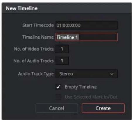
To start editing your clips, you'll need to create a new timeline.
The timeline is the stage upon which all your editing will take place.
2 Double click a clip in the media pool to open the clip in the source viewer. Use the mouse pointer to scrub the play head in the source viewer left and right until you find the start frame you want for the clip. Mark the in point with the 'I' shortcut. Do the same for the end frame using the 'O' shortcut.
3 Go to the timeline and position the timeline play head where you want your clip to be inserted.
4 To insert the clip onto the timeline, click inside the source viewer then drag the mouse pointer across to the timeline viewer. A list of edit options will appear. Select the type of edit you want.
Your clip will be placed onto the timeline using the edit type you selected. You'll find a description of each edit type and how to use them in the DaVinci Resolve manual.
A faster way to add clips to your edit is by dragging them from the media pool and dropping them directly onto the timeline where you can adjust your in and out points, position your clips, try different plug in effects, titles, and more. This particular workflow is like using the timeline as an artist's palette.
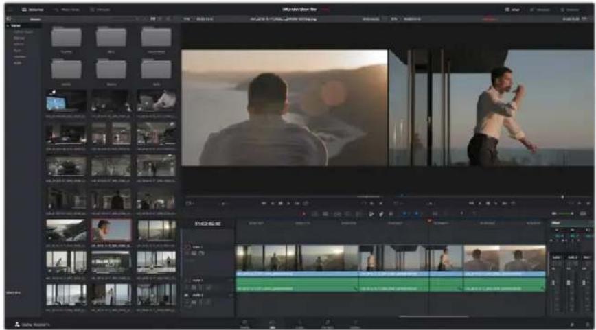
The 'edit' page. You can trim your clips, change their order, move them around and add transitions between them using the timeline editor
Trimming Clips
When editing clips you'll want to trim them to include only the specific actions you want in each shot. There are various ways, but the easiest is to adjust the clips' in and out points on the timeline:
1 After adding clips to your timeline, hover your mouse pointer over the start of a clip until the pointer becomes a 'trim' icon.
2 When the 'trim' icon appears, click on the start of your clip and drag it forwards or backwards to trim the in point. Watch the timeline monitor as you trim to find the edit point.
3 Now click and drag the end of your clip to adjust the out point.
The zoom slider is located above the timeline, to the right of the tools that are centered in the toolbar. By dragging the slider left and right you can zoom in and out of your timeline to make fine adjustments.
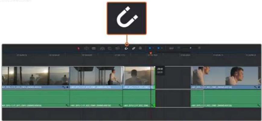
Trim your clips by dragging their start and end points left or right, and press the 'snapping' button in the toolbar to turn snapping on or off
Snapping is a helpful feature to keep your clips held tightly against each other, but can be disabled for greater precision when fine tuning edits. Press the 'N' key to quickly turn snapping on or off.
Mapping Keyboard Shortcuts
If you are familiar with keyboard shortcuts used in other editing software, you can setup DaVinci Resolve to use the same shortcuts. You also have the ability to create your own custom sets of keyboard shortcuts to increase speed and optimize your workflow.
To map your own keyboard shortcuts:
1 Open DaVinci Resolve> Preferences and select the 'user' panel at the top, then select 'keyboard mapping' from the settings list.
2 Select the shortcut you want to change from the categories provided, for example timeline cut and paste shortcuts will be in the 'edit' category.
3 Click on the shortcut once to highlight the setting. Double click on the shortcut to enable the change.
4 Press your new shortcut keys on the keyboard. If you make a mistake you can easily undo the change by clicking the 'undo' icon next to the setting.
5 Click 'save' to confirm your new shortcut setting.
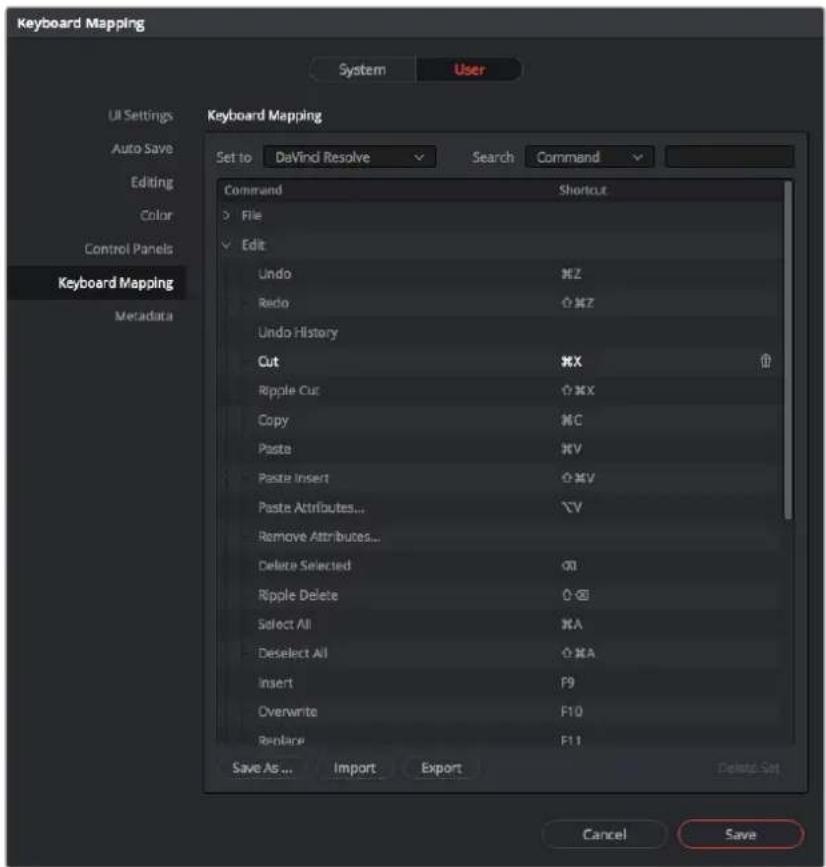
Use the 'set to' drop down menu to choose one of the keyboard shortcuts you may already be familiar with from other editing software
Adding Transitions
A transition is a visual effect used to bridge one clip to another in a pleasing way, for example dissolves, wipes, dips to color, and more. These can add a layer of excitement to your edit. Transitions don't always have to be joining two clips, for example you can apply a dissolve transition to the end of one clip to create a quick and easy fade to black.
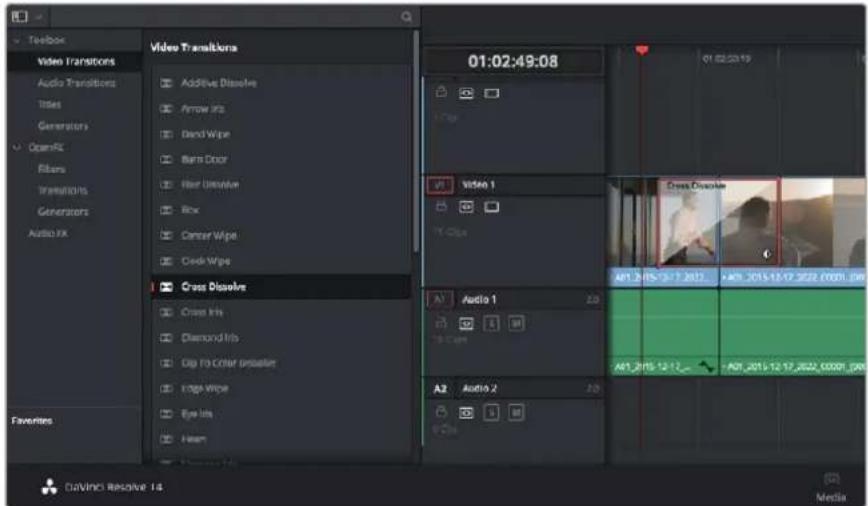
The transitions palette contains many types of transition effects
To add a dissolve transition between two clips:
1 Make sure there are two clips edited right next to one another on the timeline. Click the 'effects library' button in the UI toolbar at the top of the 'edit' page, and make sure the 'toolbox' panel is open.
2 Click on the 'cross dissolve' transition, drag it to your timeline and hover it over the edit point between two clips. You'll see the mouse pointer highlight both the end section of the first clip, and the start of the second. Drop the transition onto the clips. It's important both clips have enough length before and after their edit points to make room for the dissolve.
You now have a smooth transition mixing from one clip to the other. If you want to adjust the length of the transition you can lengthen or shorten its start and end point using a similar approach to trimming a clip. Hover your mouse pointer over the start or end of the transition until the transition 'trim' icon appears, then drag it left or right.
![01:02:52:02 01:02:51:06 01:02:51:16 01:02:52:02 A01_2015-12-17_2022_C0001 [000000-003726] Cross Dissolve A01_2015-12-17_2022_C0001_000000-003726 A01_2015-12-17_2022_C0001_000000-003726 A01_2015-12-17_2022_C0001_000000-003726](/content/2026/03/505376/images/be98f968ed7fa9f399b9279d86a18989c477ac9df140736cd62b17cd0131dfd2.jpg)
Simply drag and drop transitions between adjoining clips
Adding Titles
You can place a title on any video track just as you would a clip. If you run out of tracks you can easily add new ones by right clicking next to an existing track name and selecting 'add track'.
To create a title:
1 Scroll down towards the middle of the toolbox in the 'effects library' located underneath the media pool and you'll see the 'titles' generators. Use the scroll bar to reveal more 'titles' options.
2 Drag and drop a text title on the empty video track above the clip you want the title to appear. You can even drop your title next to a clip on Video 1 if you just want it to appear over black. To see the title, make sure the timeline playhead is on the title.
3 Double click on the title clip. The 'inspector' will appear showing you the settings for your title. Type your title into the 'text' field.
You can choose from a variety of fonts and adjust the appearance of your title by changing settings such as color, size, alignment, position, and more. Transitions can be added to titles, just like they can for clips.
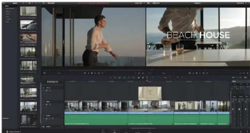
Drag a title type from the 'titles' palette and drop it on an empty track
Color Correcting your Clips
Once you have edited your sequence of clips, you can start color correcting. This is best begun after you have finished editing your sequence so you can maintain a consistent look, but part of the fun of DaVinci Resolve is being able to move between the edit and color page to make fine adjustments and discover new creative choices.
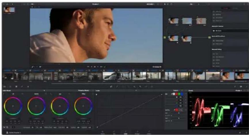
With the 'color' page you get absolute control over the look of your clips
First, click on the 'color' tab to open the 'color' page.
You'll see the color wheels, curves palettes and general color correction tools as well as the preview and nodes window. Don't feel overwhelmed by the vast array of features in front of you, they are all there to help you get the most amazing looking pictures. The DaVinci Resolve manual will show you exactly what the tools are for and how to use them in easy to follow steps. You'll learn the same techniques the professionals use in high end color correction facilities.
Generally, the first thing you'll want do is optimize the shadows, mid tones and highlights in your clips. In other words adjust the 'lift', 'gamma' and 'gain' settings. This will help get your pictures looking their brightest and best with a clean, uniform starting point from where you can begin grading the 'look' of your film.
Using Scopes
Most colorists make creative color choices by focusing on the emotion and the look they want their program to have and then simply work using the monitor to achieve that look. You can look at everyday objects and how different types of light interact with them to generate ideas on what you can do with your images and a little practice.
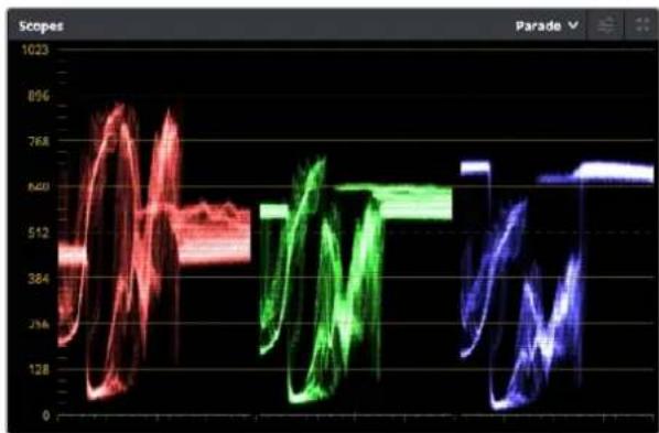
The parade scope helps you optimize highlights, mid tones and shadows
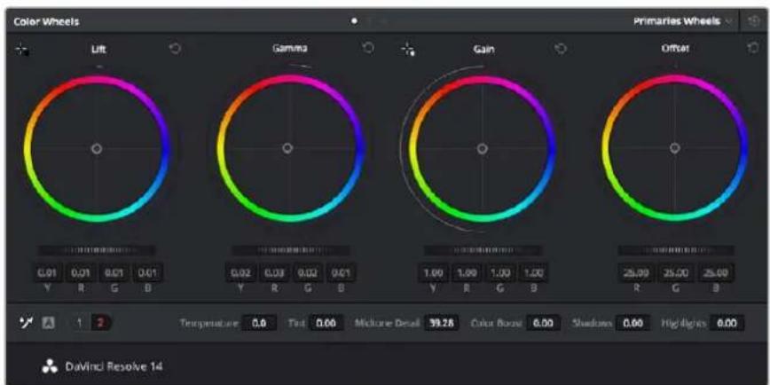
The 'lift, 'gamma', 'gain' and 'offset' color wheels give you total control over the color and tonal balance of your clips. To make a uniform adjustment to all colors for each tonal region, drag the dial underneath the color wheels back and forth
Another way to color grade is to use the built in scopes to help you balance shots. You can open a single video scope by clicking the 'scope' button, which is the second from the right on the palette toolbar. You can choose to display a waveform, parade, vectorscope and histogram. Using these scopes you can monitor your tonal balance, check the levels of your video to avoid crushing your blacks and clipping the highlights, plus monitor any color cast in your clips.
The ‘color wheels’ palette contains the ‘lift’, ‘gamma’ and ‘gain’ controls which will generally constitute your first adjustment. These should resemble controls you’ve seen in other applications for doing color and contrast adjustments. For more accurate control of each color using a mouse, you can change the color wheels to ‘primaries bars’ which let you adjust each color and luminance channel for the lift, gamma and gain controls separately. Simply select ‘primaries bars’ from the drop down menu near the top right of the color wheels.
1 Adjusting the 'lift'
With your first clip selected on the color timeline, click on the 'lift' dial underneath the first color wheel. Slide it back and forth and watch how it affects your image. You'll see the brightness of the dark regions of your picture increase and decrease.
Set it to where you want the dark areas to look their best. If you decrease the lift too much, you'll lose details in the blacks and you can use the parade scope to help avoid this. The optimal position for blacks on the waveform is just above the bottom line of the parade scope.
2 Adjusting the 'gain'
Click on the 'gain' dial and slide it back and forth. This adjusts the highlights which are the brightest areas of your clip. The highlights are shown on the top section of the waveform on the parade scope. For a brightly lit shot, these are best positioned just below the top line of the waveform scope. If the highlights rise above the top line of the waveform scope, they will clip and you will lose details in the brightest regions of your image.
3 Adjusting the 'gamma'
Click on the ‘gamma’ dial underneath the color wheel and slide it back and forth. As you increase the gamma you’ll see the brightness of the image increase. Notice the middle section of the waveform will also move as you adjust the gamma. This represents the mid tones of your clip. The optimal position for mid tones generally falls between 50 to 70% on the waveform scope. However, this can be subjective based on the look you are creating and the lighting conditions in the clip.
You can also use the curves palette to make primary color corrections. Simply click to create control points on the diagonal line inside the curve graph, and drag them up or down to adjust the master RGB contrast at different areas of image tonality. The optimum points to adjust are the bottom third, mid, and top third of the curve line.
There are many more ways of doing primary color correction in DaVinci Resolve. Check the DaVinci Resolve manual to learn how to use them all.
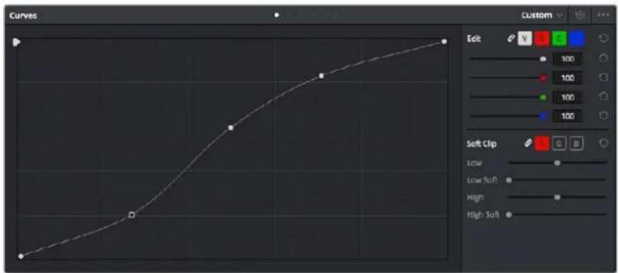
The curves palette is another tool you can use to make primary color corrections, or enhance specific areas of your clip when using a power window
Secondary Color Correction
If you want to adjust a specific part of your image then you need to use secondary corrections. The adjustments you have been doing up until now using the color wheels and lift, gamma and gain adjustments affect the whole image at the same time and so they are called primary color corrections.
However if you need to adjust specific parts of your image, say for example you wanted to improve the color in the grass in a scene, or you wanted to deepen the blue in a sky, then you can use secondary corrections. Secondary color corrections are where you select a part of the image and then adjust just that part. With nodes, you can stack multiple secondary corrections so you can keep working parts of your image until everything is just right! You can even use windows and tracking to allow the selections to follow movement in your images.
Qualifying a Color
Often you'll find a specific color in your clip can be enhanced, for example grass by the side of a road, or the blue in a sky, or you may need to adjust color on a specific object to focus the audience's attention on it. You can easily do this by using the HSL qualifier tool.

natural_image
Silhouette of a human head against a blue sky background (no text or symbols)Using the HSL qualifier to select colors in your image is helpful when you want to make areas of your image 'pop', to add contrast, or to help draw the audience's attention to certain areas of your shot
To qualify a color:
1 Add a new serial node.
2 Open the 'qualifier' palette and make sure the 'color range' sample eyedropper tool is selected.
3 Click on the color in your clip you want to affect.
4 Usually you'll need to make some adjustments to soften the edges of your selection and limit the region to only the desired color. Click on the 'highlight' button to see your selection.
5 Adjust the 'width' control in the 'hue' window to broaden or narrow your selection.
Experiment with the high, low and softness controls to see how to refine your selection.
Now you can make corrections to your selected color using the color wheels or custom curves.
Sometimes your selection can spill into areas of the shot you don't want to affect. You can easily mask out the unwanted areas using a power window. Simply create a new window and shape it to select only the area of color you want. If your selected color moves in the shot, you can use the tracking feature to track your power window.
Adding a Power Window
Power windows are an extremely effective secondary color correction tool that can be used to isolate specific regions of your clips. These regions don't have to be static, but can be tracked to move with a camera pan, tilt or rotation, plus the movement of the region itself.
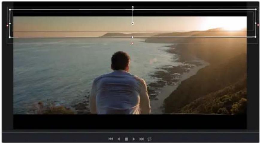
natural_image
Person sitting by a coastal cliff at sunset, overlooking the sea with hills in the background (no text or symbols visible)Use power windows to mask out areas you don't want to be affected by the HSL qualifier secondary adjustments
For example, you can track a window on a person in order to make color and contrast changes just to that person without affecting his or her surroundings. By making corrections like this you can influence the audience's attention on areas you want them to look at.
To add a power window to your clip:
1 Add a new serial node.
2 Open the 'window' palette and select a window shape by clicking on a shape icon. Your selected window shape will appear on the node.
3 Resize the shape by clicking and dragging the blue points around the shape. The pink points adjust the edge softness. You can position the shape by clicking the center point and moving it to the area you want to isolate. Rotate the window using the point connected to the center.
Now you can make color corrections to your image in just the area you want.
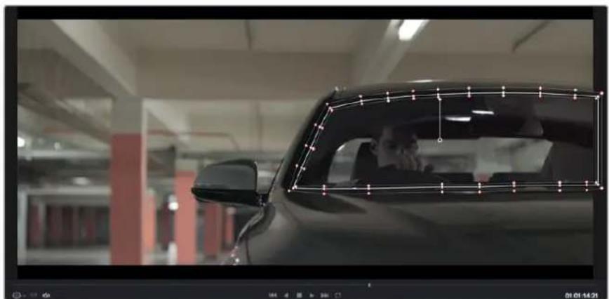
natural_image
Interior view of a car with a person visible through the window frame (no text or symbols)Power windows let you make secondary corrections to specific parts of your Image
Tracking a Window
The camera, object or area in your shot may be moving, so to make sure your window stays on your selected object or area, you'll need to use DaVinci Resolve's powerful tracking feature. The tracker analyzes the pan, tilt, zoom and rotation of the camera or object in your clip so you can match your windows to that movement. If this isn't done, your correction can move off the selected target and call attention to itself, which you probably don't want.
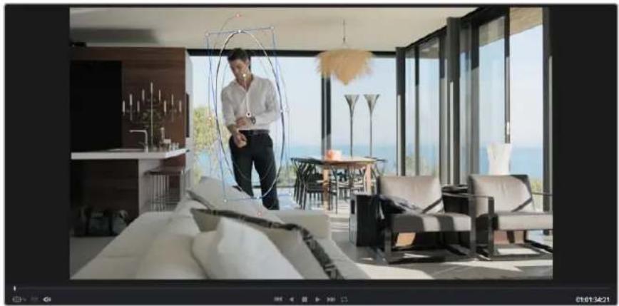
natural_image
Modern living room interior with large windows overlooking the sea, featuring a man standing near a circular metal frame and patterned chairs (no visible text or symbols)You can track objects or areas in your clip using the tracker feature so power windows can follow the action
To track a window to a moving object:
1 Create a new serial node and add a power window.
2 Go to the start of your clip and position and size the window to highlight just the object or area you want.
3 Open the 'tracker' palette. Select the pan, tilt, zoom, rotate, and perspective 3D settings appropriate for the movement in your clip by checking or unchecking the relevant 'analyse' checkboxes.
4 Click on the 'forward' arrow to the left of the checkboxes. DaVinci Resolve will now apply a cluster of tracking points on your clip and then step through the frames to analyze the movement. When the tracking is done, your power window will follow the path of the movement in your clip.
Most of the time automatic tracking is successful, but scenes can be complex and sometimes an object can pass in front of your selected area, interrupting or affecting your track. This can be solved manually using the keyframe editor. Refer to the DaVinci Resolve manual to find out more.
Using Plugins
While making secondary color corrections you can also add OpenFX plugins to create fast, interesting looks and effects using the 'color' page, or imaginative transitions and effects on your clips on the 'edit' page. OFX plugins can be purchased and downloaded from third party suppliers.
After installing a set of plugins, you can access them on the color page by opening the OpenFX inspector to the right of the 'node editor' Simply click the 'OpenFX' button to open the OpenFX inspector, create a new serial node and drag and drop a plugin onto the new node. If the plugin has editable settings, you can adjust these in the adjoining 'settings' panel.
In the 'edit' page you can add plugin generators and transitions to clips by opening the 'OpenFX' panel in the 'effects library' and dragging your selected plugin onto the video track above your clip on the timeline.
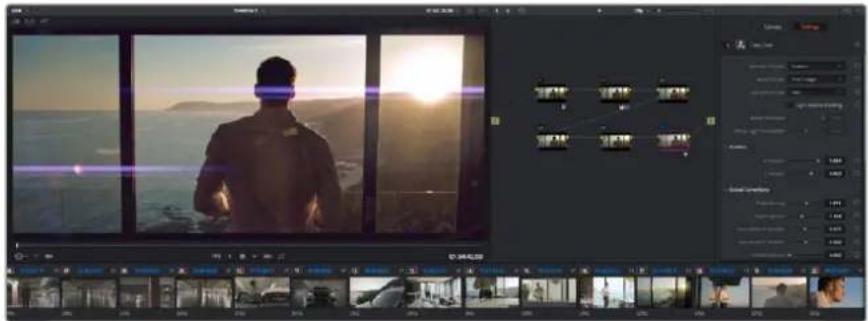
OFX plugins are a quick and easy way to create an imaginative and interesting look
Mixing Your Audio
Mixing Audio in the Edit Page
Once you have edited and color corrected your project, you can begin to mix your audio. DaVinci Resolve has a helpful set of features for editing, mixing and mastering audio for your project directly in the 'edit' page. For projects requiring more advanced audio tools, the Fairlight page provides you with a full audio post production environment, and if you are already familiar with the edit page and want to move straight to Fairlight, skip this section and move onto the next.
Adding Audio Tracks
If you are working in the edit page and want to mix a basic sound edit with lots of sound effects and music, you can easily add more audio tracks when you need them. This can be helpful when building your sound, and separating your audio elements into individual tracks, for example, dialogue, sound effects and music.
To Add an Audio Track to the Edit Page:
1 Right click next to the name of any audio track on your timeline and select 'add track'. This will add a track to the bottom of the track list. Alternatively select 'add tracks' and select the location you would like the new track placed.
2 Select the type of audio track you want, such as stereo, mono, 5.1 or adaptive.
Your new audio track will appear on the timeline.
Adjusting Audio Levels in the Timeline
Each clip of audio in the timeline has a volume overlay that lets you set that clip's level by simply dragging it up or down with the pointer. This overlay corresponds to the Volume parameter in the Inspector.
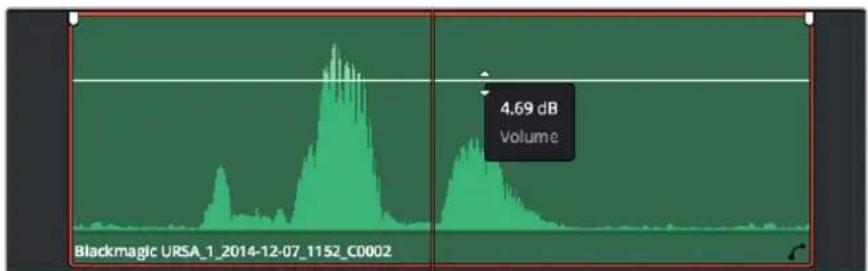
line
| Time | Volume | |------|--------| | Peak | 4.69 dB |Dragging a volume overlay to adjust the clip level
For projects requiring more advanced audio tools, the Fairlight page provides you with a full audio post production environment.
The Fairlight Page
The 'Fairlight' page in DaVinci Resolve is where you adjust your project audio. In single monitor mode, this page gives you an optimized look at the audio tracks of your project, with an expanded mixer and custom monitoring controls that make it easy to evaluate and adjust levels in order to create a smooth and harmonious mix. Don't feel overwhelmed by the vast array of features in front of you, they are all there to help you deliver the best audio quality for your project.
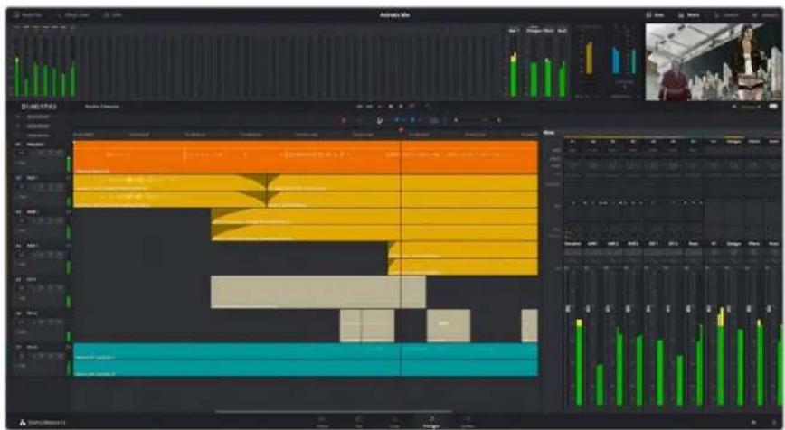
This guide provides a basic overview of the features on the Fairlight page, but to learn more about all the details for each feature, refer to the DaVinci Resolve manual. The DaVinci Resolve manual provides details on the purpose of each tool and describes how to use them in easy to follow steps.
The Audio Timeline
Track Header
At the left of each track is a header area that displays the track number, track name, track color, audio channels, fader value and audio meters. The track header also contains different controls for locking and unlocking tracks, plus solo and muting controls. These controls can help to keep your tracks organized, and let you preview individual tracks one at a time.
Tracks
Each track on the Fairlight page is divided into lanes, which show each individual channel of clip audio for editing and mixing. The edit page hides these individual audio channels, displaying only a single clip in the timeline to make it easier to edit multi channel sources without needing to manage a huge number of tracks.
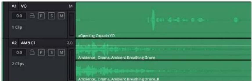
The track header on track A1 indicates a mono track with a single lane for mono audio, whilst track A2 indicates a stereo track with two lanes to accommodate stereo audio
What is a Bus?
A bus is essentially a destination channel to which you can route multiple audio tracks from the timeline, so that they are mixed together into a single signal that can be controlled via a single channel strip.
Main Bus
'Main busses' are typically the primary output of a program and each new project you create starts out with a single 'main bus', to which all tracks are routed by default. The 'main bus' combines all of the tracks in the timeline into one signal so that you can adjust the overall level of the audio mix once you have adjusted the level of each individual track.
Sub Bus
'Sub busses' allow you to combine multiple tracks of audio that belong to the same category such as dialogue, music or effects so that everything in that category can be mixed as a single audio signal. For example, if you have five dialogue tracks, you can route the output of all five dialogue tracks to a 'submix bus', and the level of all dialogue can then be mixed with a single set of controls. This submix can be rendered separately or sent to the main bus for render.
The Mixer
Each audio track in your timeline corresponds to an individual channel strip in the Mixer, and by default there's a single strip on the right for the 'main bus' labeled 'M1'. Additional channel strips will appear on the right hand side with a set of controls for each additional 'main' and 'submix bus' you create. A set of graphical controls allows you to assign track channels to output channels, adjust EQ and dynamics, set levels and record automation, pan stereo and surround audio, and mute and solo tracks.
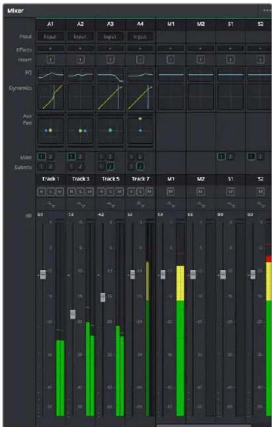
The audio mixer, with channel strips corresponding to the tracks in the timeline
Using the Equalizer to Enhance your Audio
After adjusting the audio levels of your audio clips in your project, you may find that the audio needs further finessing. In some cases you may find that the dialogue, music and sound effects are competing for the same frequency on the audio spectrum, making your audio too busy and unclear. This is where using EQ can help, as it allows you to specify the parts of the audio spectrum that each track occupies. You can also use an equalizer to help remove unwanted elements from your audio by isolating and reducing the level on particular frequencies that contain low rumbles, hums, wind noise and hiss, or simply to improve the overall quality of your sound so it is more pleasing to listen to.
DaVinci Resolve provides EQ filters that can be applied at a clip level to each individual clip or at the track level to affect entire tracks. Each audio clip in the timeline has a four band equalizer in the inspector panel, and each track has a 6 band parametric equalizer in the mixer panel. The graphical and numeric controls for boosting or attenuating different ranges of frequencies, and different filter types allow you to define the shape of the EQ curve.
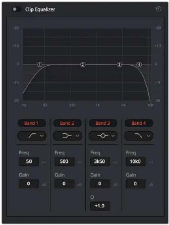
The four band equalizer can be applied to every clip in the timeline
Outer bands let you make band filter adjustments using hi-shelf, lo-shelf, hi-pass and lo-pass filters. A pass filter affects all the frequencies above or below a particular frequency, by removing those frequencies completely from the signal. For example, a high pass filter will allow the high frequencies to pass through the filter whilst cutting the low frequencies. Any frequencies outside the cutoff frequency are cut gradually in a downward sloping curve.
A shelf filter is less aggressive, and is useful when you want to shape the overall top end or low end of the signal without completely removing those frequencies. The shelf filter boosts or cuts the target frequency and every frequency either above or below it evenly, depending on whether you use a high shelf or low shelf.
The middle sets of band controls let you make a wide variety of equalization adjustments, and can be switched between lo-shelf, bell, notch, and hi-shelf filtering options.
Bell
Bell filters boost or cut frequencies around a given center point of the bell curve, and as the name suggests the shape of the curve is like a bell.
Notch
Notch filters allow you to specifically target a very narrow range of frequencies. For example, removing a mains hum at 50 or 60Hz.
Lo-Shelf
Low shelf filters boost or cut the target frequency at the low end, and every frequency below it
Hi-Shelf
High shelf filters boost or cut the target frequency at the high end, and every frequency above it
To add EQ to an individual clip:
1 Select the clip in the timeline that you want to add the EQ filter to.
2 Click on the inspector and then click the 'clip equalizer' enable button.
To add EQ to a track:
1 Double-click in the EQ section for one of your tracks in the mixer to open the equalizer for that track.
2 Select the band filter type from the drop down menu for the band you want to adjust.

The EQ section in the mixer panel indicating an EQ curve has been applied to track one
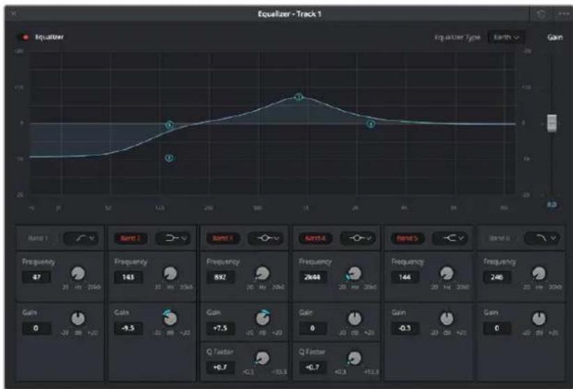
line
| Frequency | Gain | | --------- | ---- | | 0 | -9.5 | | 10 | +7.5 | | 20 | 892 | | 30 | 2644 | | 40 | 144 | | 50 | 246 | | 60 | -0.3 | | 70 | 0 |The 6 Band parametric equalizer that can be applied to every track
Once you have added EQ to your clip or track, you can adjust the EQ for each band. Note that controls may vary depending on which band filter type is selected.
To adjust the EQ for a band filter:
1 Select the band filter type from the drop down menu for the band you want to adjust.
2 Adjust the 'frequency' value to select the center frequency of the EQ adjustment.
3 Adjust the 'gain' value to boost or attenuate the frequencies governed by that band.
4 Use the 'Q factor' value to adjust the width of affected frequencies.
Use the reset button to reset all controls in the EQ window to their defaults.
Fairlight has many controls you can use to improve the quality of each audio track. You can add more tracks and arrange buses to organize them, plus add effects like delay or reverb, and generally perfect your audio mix.
Mastering your Edit
So now you've edited, graded your clips and mixed your audio, you'll want to export a render of your edit in the 'deliver' page. This page lets you select the range of clips you want to export, plus the format, codec and resolution you want. You can export in many types of formats such as QuickTime, AVI, MXF and DPX using codecs such as 8-bit or 10-bit uncompressed RGB/YUV, ProRes, DNxHD, H.264 and more.
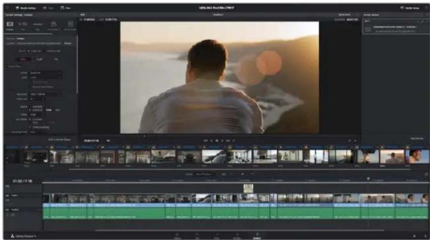
The 'deliver' page is where you export your edit. You can select from many different video formats and codecs
To export a single clip of your edit:
1 Click on the 'deliver' tab to open the deliver page.
2 Go to the 'render settings' window on the top left of the page. In the 'format' settings, select 'single clip'. You can now choose from a number of export presets, for example YouTube, Vimeo and audio presets, or you can set your own export settings manually by leaving it set to the default 'custom' preset and entering your own parameters.
For this example, select YouTube, then click on the arrow next to the preset and select the 1080p video format.
The frame rate will be locked to your project frame rate setting.
3 Underneath the presets you will see the timeline filename and the target location for your exported video. Click the 'browse' button and choose the location where you want to save your exported file.
4 Immediately above the timeline, you'll see an options box with 'entire timeline' selected. This will export the entire timeline, however you can select a range of the timeline if you want to. Simply choose 'in/out range' and then use the 'i' and 'o' hot key shortcuts to choose the in and out points in your timeline.
5 Go to the bottom of the 'render settings' and click on the 'add to render queue' button.
Your render settings will be added to the render queue on the right side of the page. Now all you have to do is click 'start render' and monitor the progress of your render in the render queue.
When your render is complete you can open the folder location, double click on your new rendered clip and watch your finished edit.
Camera Video Output
Connecting to Monitors
HDMI monitoring can be helpful when accessing the LCD is impractical, such as when the camera is secured high on a jib arm, on a crane, or mounted on a vehicle.
Monitoring information is displayed on your HDMI output by adjusting the HDMI overlays options in the display settings menu. HDMI overlays provide frame guides and information such as recording details and camera settings. If you simply want to monitor your shots, you can always turn overlays off for a clean HDMI output.
Blackmagic Camera Setup Software
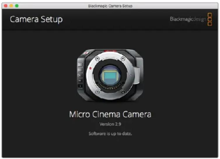
How to Update Your Camera Software on Mac OS X
After downloading the 'Blackmagic Camera Setup' software, unzip the downloaded file and double click on the .dmg disk image file. Launch the 'Blackmagic Camera Setup' installer and follow the onscreen instructions.
How to Update Your Camera Software on Windows
After downloading the 'Blackmagic Camera Setup' software and unzipping the downloaded file, you should see a 'Blackmagic Camera Setup' installer window. Double click on the installer icon and follow the onscreen prompts to complete the installation.
After the installation is complete, click on the Windows 'start' menu, and go to 'all programs'. Click on the Blackmagic Design folder to open the Blackmagic Camera setup software and instruction manuals.
How to Update your Camera's Internal Software
After installing the latest Blackmagic Camera setup software on your computer, connect a USB cable between the computer and your camera. On Blackmagic Pocket Cinema Camera, the Mini USB 2.0 port is located inside the battery terminal.
Launch ‘Blackmagic Camera Setup’ and follow the onscreen prompts to update the camera software.
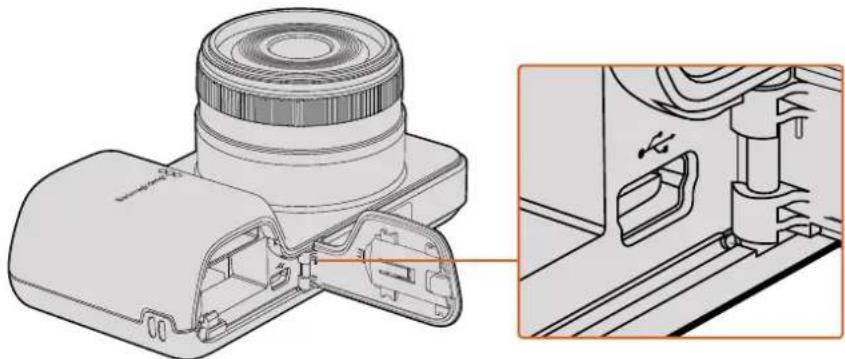
natural_image
Technical illustration of a device's internal structure showing a lens assembly and a close-up view of the component (no text or symbols present)The Mini-USB 2.0 port can be found behind the battery terminal door on Blackmagic Pocket Cinema Camera
Post Production Workflow
Working with Files from SD Cards
You can access your ProRes or CinemaDNG files straight from your SD card with any Mac OS X or Windows computer that features an SD card slot or by using an SD card reader.
1 Remove the SD card from your Blackmagic compact camera and insert it into the SD card slot of your computer, or SD card reader. The SD card can be accessed the same way as you would an external hard drive, USB drive or any other media storage device attached to your computer.
2 Double click on the SD card to open it and you should see a list of QuickTime movie files or folders which contain your CinemaDNG RAW image files. Depending on the format you chose to record in, you might have a mixture of files and folders, but they will all use the same naming convention.
3 Now you can simply drag the files you want from the SD card onto your desktop or another hard drive, or you can access the files straight from the SD card using your NLE software.
4 Before you physically remove the SD card from the SD card slot, it's always a good idea to eject the SD card safely using either Mac OS X or Windows first.
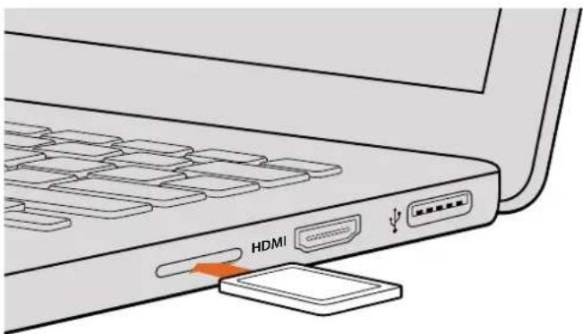
Insert your SD card into any computer with an SD card slot to access your clips immediately
Working with 3rd Party Software
If you have your own favourite editing software you'd like to use, you can easily copy your clips to an internal/external drive or RAID and then import your clips into the software. If you want to, you can even edit your clips directly from the SD card using a card reader.
Using Final Cut Pro X
To edit Apple ProRes 422 HQ clips using Final Cut Pro X, you need to create a new project matching your clips' video format and frame rate. For this example, clips are set using ProRes 422 HQ 1080p25 camera settings.
1 Launch Final Cut Pro X, go to the menu bar and select 'file/new project'. A window will open containing project settings.
2 Name your project and select the 'custom' checkbox.
3 Set the 'video properties' settings to 1080p HD, 1920x1080 and 25p.
4 Set your 'audio and render properties' settings to 'stereo, 48kHz, and Apple ProRes 422 HQ'
5 Click 'ok'.
To import your clips into your project, go to the menu bar and select 'file/import/media'. Choose your clips from your SD Card.
You can now drag your clips onto the timeline for editing.
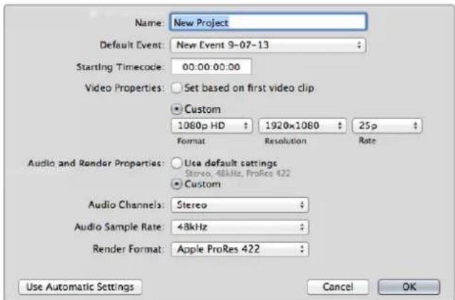
Final Cut Pro X project settings
Using Avid Media Composer
To edit your DNxHD clips using Avid Media Composer 7, create a new project matching the clip's video format and frame rate. For this example, clips are set using DNxHD 1080i59.94 camera settings.
1 Launch Media Composer and the 'select project' window will appear. Click the 'new project' button.
2 In the 'new project' window name your project.
3 Go to the 'format' dropdown menu and select 1080i/59.94.
4 Go to the 'color space' dropdown menu and select YCbCr 709.
5 Go to the 'raster dimension' dropdown menu and select 1920x1080. Click 'ok'.
6 Select 'tools>background services' and click the 'start' button if background services are not already running and then click 'ok'.
7 Select the media bin where you wish to import your files.
8 Select 'file>AMA link...' and select the files that you wish to import and then click 'ok'.
When the clips appear within the media bin you can drag your clips onto the timeline and begin editing.
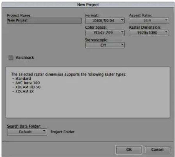
Setting the project name and project options in Avid Media Composer 7
Using Adobe Premiere Pro CC
To edit your Apple ProRes 422 HQ or DNxHD clips using Adobe Premiere Pro CC, you need to create a new project matching your clips' video format and frame rate. For this example, clips are set using ProRes 422 HQ 1080p25 camera settings.
1 Launch Adobe Premiere Pro CC. In the 'welcome' window select 'create new/new project'. A window will open containing project settings.
2 Name your project. Choose the location for your project by clicking 'browse' and selecting your desired folder. Once you've selected your location folder click 'ok' in the 'welcome' window.
3 Go to the Adobe Premiere Pro CC menu bar, select 'file/import' and choose the clips you want to edit. Your clips will appear in the 'project' window.
4 Drag the first clip you wish to edit onto the 'new item' icon at the bottom right of the 'project' window. A new sequence will be created matching your clip settings.
You can now drag your clips onto the sequence timeline for editing.
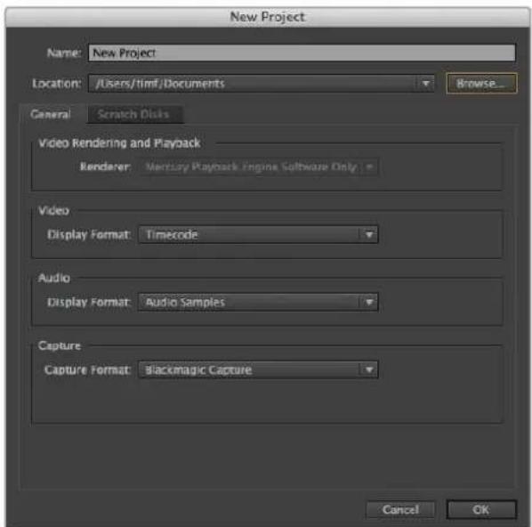
Setting the project name and project options in Adobe Premiere Pro CC
Using Autodesk Smoke
To edit your clips using Autodesk Smoke 2013, create a new project matching the clips' video format, bit depth, frame type and frame rate. For this example, clips were shot using ProRes 422 HQ 1080p25 camera settings.
1 Launch Smoke and the project and user settings window will appear. Click on the 'new' button under the project heading.
2 The 'create new project' window will open. Name your project.
3 From the resolution dropdown menu, select 1920x1080 HD 1080.
4 Make sure bit depth is set to 10-bit and frame type is progressive.
5 From the config template dropdown menu select 1920x1080@25000p.cfg.
6 Leave the 'preferred format' set to ProRes 422 HQ and click 'create'.
7 Click on the 'new' button under the user heading.
8 When the 'create new user profile' window opens, type your user name and click 'create'.
9 When the project and user settings window reopens, click the start button.
10 From the menu bar, select 'file>import>file' and select your clips to import.
11 Once the clips appear in the media library you can drag your clips onto the timeline and begin editing.
![Create New Project Name: Blackmagic Volume: AutodeskMediaStorage Frames Free 309207 Frames Used 0 Setup Directory: [Blackmagic] Setup Mode: New Settings Config Template: 1520x1000@3997p.dfo Resolution: 1520 x 1000 HD 1000 Width 1520 Height 1000 Set to 16.4 Ratio 1.777/8 8-bit Progressive 16 bit FP Graphics Cache and Renderers Proxy Settings Preferred Format Format Restrictions Profiles #22 (HC) Maximum Width None Maximum Height None Depths 10-bit, 12-bit Alternate Formats DPX, EXR, RAW Reset Cancel Create](/content/2026/03/505376/images/12424449978d1033c661dd6456a9058bc4c46e199e064b6e9f79dee4312a20a9.jpg)
Setting the project name and project options in Autodesk Smoke
Attaching Accessories
Wrist Strap
Blackmagic Pocket Cinema Camera comes with a wrist strap for convenient carrying of the camera when on the move from location to location.
To fasten, loop the string on the end of the strap through the ring on the camera, located to the bottom right of the LCD. Loop the rope end of the wrist strap back through the string, making a secure knot.
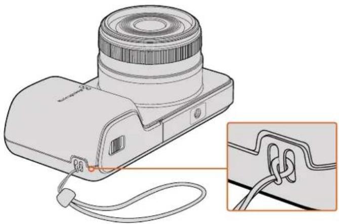
natural_image
Diagram of a camera with attached cable and lens, showing internal components and wiring (no text or symbols)Blackmagic Pocket Cinema Camera wrist strap
Help
Getting Help
The fastest way to obtain help is to go to the Blackmagic Design online support pages and check the latest support material available for your camera.
Blackmagic Design Online Support Pages
The latest manual, software and support notes can be found at the Blackmagic Design support center at www.blackmagicdesign.com/support.
Contacting Blackmagic Design Support
If you can't find the help you need in our support material, please use the "Send us an email" button on the support page to email a support request. Alternatively, click on the "Find your local support team" button on the support page and call your nearest Blackmagic Design support office.
Checking the Software Version Currently Installed
To check which version of Blackmagic Camera Setup software is installed on your computer, open the About Blackmagic Camera Setup window.
- On Mac OS X, open Blackmagic Camera Setup from the Blackmagic Cameras folder in the Applications Folder. Select About Blackmagic Camera Setup from the application menu to reveal the version number.
- On Windows, open Blackmagic Camera Setup from your Start menu or Start Screen. Click on the Help menu and select About Blackmagic Camera Setup to reveal the version number.
How to Get the Latest Software Updates
After checking the version of Blackmagic Camera Utility software installed on your computer, please visit the Blackmagic Design support center at www.blackmagicdesign.com/support to check for the latest updates. While it is usually a good idea to run the latest updates, it is wise to avoid updating any software if you are in the middle of an important project.
Warranty
Limited Warranty
Blackmagic Design warrants that this product will be free from defects in materials and workmanship for a period of 12 months from the date of purchase. If a product proves to be defective during this warranty period, Blackmagic Design, at its option, either will repair the defective product without charge for parts and labor, or will provide a replacement in exchange for the defective product.
In order to obtain service under this warranty, you the Customer, must notify Blackmagic Design of the defect before the expiration of the warranty period and make suitable arrangements for the performance of service. The Customer shall be responsible for packaging and shipping the defective product to a designated service center nominated by Blackmagic Design, with shipping charges pre paid. Customer shall be responsible for paying all shipping charges, insurance, duties, taxes, and any other charges for products returned to us for any reason.
This warranty shall not apply to any defect, failure or damage caused by improper use or improper or inadequate maintenance and care. Blackmagic Design shall not be obliged under this warranty: a) to repair damage resulting from attempts by personnel other than Blackmagic Design representatives to install, repair or service the product, b) to repair damage resulting from improper use or connection to incompatible equipment, c) to repair any damage or malfunction caused by the use of non Blackmagic Design parts or supplies, or d) to service a product that has been modified or integrated with other products when the effect of such a modification or integration increases the time or difficulty of servicing the product.
Exposing URSA Viewfinder to direct sunlight could damage the viewfinder display as the viewfinder optics act as a magnifying glass. Image retention or burn-in could happen on OLED panels when static or high contrast images, such as frame guides, are displayed on the panels for extended periods. To avoid this, ensure the IR sensor for face detection is not covered deliberately and disconnect the viewfinder when not in use for prolonged periods. Image retention is not covered by this product warranty.
THIS WARRANTY IS GIVEN BY BLACKMAGIC DESIGN IN LIEU OF ANY OTHER WARRANTIES, EXPRESS OR IMPLIED. BLACKMAGIC DESIGN AND ITS VENDORS DISCLAIM ANY IMPLIED WARRANTIES OF MERCHANTABILITY OR FITNESS FOR A PARTICULAR PURPOSE. BLACKMAGIC DESIGN'S RESPONSIBILITY TO REPAIR OR REPLACE DEFECTIVE PRODUCTS DURING THE WARRANTY PERIOD IS THE WHOLE AND EXCLUSIVE REMEDY PROVIDED TO THE CUSTOMER. BLACKMAGIC DESIGN WILL NOT BE LIABLE FOR ANY INDIRECT, SPECIAL, INCIDENTAL OR CONSEQUENTIAL DAMAGES IRRESPECTIVE OF WHETHER BLACKMAGIC DESIGN OR THE VENDOR HAS ADVANCE NOTICE OF THE POSSIBILITY OF SUCH DAMAGES. BLACKMAGIC DESIGN IS NOT LIABLE FOR ANY ILLEGAL USE OF EQUIPMENT BY CUSTOMER. BLACKMAGIC IS NOT LIABLE FOR ANY DAMAGES RESULTING FROM USE OF THIS PRODUCT. USER OPERATES THIS PRODUCT AT OWN RISK.
© Copyright 2017 Blackmagic Design. All rights reserved. 'Blackmagic Design', 'URSA', 'DeckLink', 'HDLink', 'Workgroup Videohub', 'Multibridge Pro', 'Multibridge Extreme', 'Intensity' and 'Leading the creative video revolution' are registered trademarks in the US and other countries. All other company and product names may be trademarks of the respective companies with which they are associated.
natural_image
Circular portrait photo of a smiling man in a dark shirt against a gray background (no text or symbols)ようこそ
Blackmagic Design CEO
グラント・ペティ
目次
Blackmagic Design Compact Cameras
はじめに 69
レンズの取り 付け 69
カメラの電源を入れる 70
メディアのインストール 71
SDカードの使用 71
SDカードについて 72
高速のSDカードを選ぶ 72
撮影用にメディアを準備する 73
ディスクスピードの確認 76
収録 76
クリップの収録 76
トリガー 収録 77
再生 78
クリップの再生 78
カメラ接 続 79
Blackmagic Pocket Cinema Camera 79
Blackmagic Micro Cinema Camera 80
Blackmagic Micro Cinema
Camera 拡張ケーブル配線図 82
タリーライトインジケー ター 83
Blackmagic Micro Cinema
Camera タリーライト 83
メニュー設定 84
ダッシュボード 84
カメラ設定 84
オーディオ設定 (Audio) 87
natural_image
Illustration of a digital camera with a circular lens and orange arrow indicating the lens (no text or symbols present)
natural_image
Illustration of a digital camera with an orange arrow indicating rotation (no text or symbols present)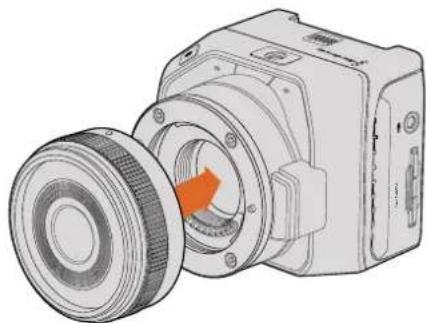
natural_image
Technical illustration of a mechanical device with a pulley and housing (no text or symbols)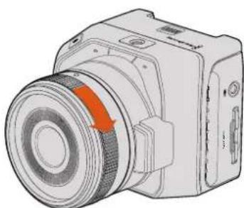
natural_image
Illustration of a camera with an orange arrow indicating rotation or motion (no text or symbols present)natural_image
Diagram of a camera module with an orange rotation arrow indicating the operation (no text or symbols present)Blackmagic Pocket Cinema Cameraにバッテリーを挿入
natural_image
Diagram of a camera module with lens and internal components, showing no text or symbolsnatural_image
Diagram of a digital camera with lens and external connector (no text or symbols)
gauge
| Metric | Value | |--------|-------| | Current | 432.5 | | Peak Speed | 432.5 (MB/s) |natural_image
Illustration of a handheld electronic device with control buttons and a highlighted indicator button (no text or symbols)natural_image
Line drawing of a black-and-white digital camera with lens and control buttons (no text or symbols)LANC リモートコントロール
natural_image
Line drawing of a digital camera module with control buttons and ports (no text or symbols)HDMI出力
natural_image
Diagram of a device with a USB symbol and an inset showing the same switch (no text or labels present)natural_image
Diagram of a camera with red highlighted lens and inset showing internal components (no text or symbols)natural_image
Street scene with a person walking past parked bicycles under a sunset sky (no visible text or symbols)natural_image
Silhouette of two prominent mountain peaks on a wooden surface, no text or symbols visiblenatural_image
Abstract circular arrow symbol with the letter 'A' at the center, no text or labels present.line
| Time | Red Line Value | Green Line Value | Blue Line Value | |------|----------------|------------------|-----------------| | 0 | 512 | 512 | 512 | | 1 | 768 | 768 | 768 | | 2 | 896 | 896 | 896 | | 3 | 768 | 768 | 768 | | 4 | 512 | 512 | 512 | | 5 | 384 | 384 | 384 | | 6 | 256 | 256 | 256 | | 7 | 128 | 128 | 128 | | 8 | 0 | 0 | 0 | | 9 | 0 | 0 | 0 | | 10 | 0 | 0 | 0 | | 11 | 0 | 0 | 0 | | 12 | 0 | 0 | 0 | | 13 | 0 | 0 | 0 | | 14 | 0 | 0 | 0 | | 15 | 0 | 0 | 0 | | 16 | 0 | 0 | 0 | | 17 | 0 | 0 | 0 | | 18 | 0 | 0 | 0 | | 19 | 0 | 0 | 0 | | 20 | 0 | 0 | 0 | | 21 | 0 | 0 | 0 | | 22 | 0 | 0 | 0 | | 23 | 0 | 0 | 0 | | 24 | 0 | 0 | 0 | | 25 | 0 | 0 | 0 | | 26 | 0 | 0 | 0 | | 27 | 0 | 0 | 0 | | 28 | 0 | 0 | 0 | | 29 | 0 | 0 | 0 | | 30 | 0 | 0 | 0 | | 31 | 0 | 0 | 0 | | 32 | 0 | 0 | 0 | | 33 | 0 | 0 | 0 | | 34 | 0 | 0 | 0 | | 35 | 0 | 0 | 0 | | 36 | 0 | 0 | 0 | | 37 | 0 | 0 | 0 | | 38 | 0 | 0 | 0 | | 39 | 0 | 0 | 0 | | 40 | 0 | 0 | 0 | | 41 | 0 | 0 | 0 | | 42 | 0 | 0 | 0 | | 43 | 0 | 0 | 0 | | 44 | 0 | 0 | 0 | | 45 | 0 | 0 | 0 | | 46 | 0 | 0 | 0 | | 47 | 0 | 0 | 0 | | 48 | 0 | 0 | 0 | | 49 | 0 | 0 | 0 | | 50 | 0 | 0 | 0 | | ... (repeated) for all values in the chart: Scopes = (x,y) for each series. The y-axis is labeled 'Scope'. The x-axis is labeled 'Time' with 'Period' as the index of the series. Legend: 'Parade' indicates the series.natural_image
Silhouette of a human head against a blue sky background (no text or symbols)natural_image
Person sitting by a coastal cliff at sunset, overlooking the sea with hills in the background (no text or symbols visible)natural_image
Black car inside a parking garage with red pillars and ceiling lights (no visible text or symbols)natural_image
Interior view of a modern living room with large windows, high furniture, and a man standing near a circular metal frame (no visible text or symbols)line
| Metric | Value | | ------------ | ----- | | Gain | 0 | | Gain | -9.5 | | Gain | +7.5 | | Gain | -0.7 | | Gain | -0.3 | | Gain | 0 | | Gain | 0 | | Gain | 0 | | Gain | 0 | | Gain | 0 | | Gain | 0 | | Gain | 0 | | Gain | 0 | | Gain | 0 | | Gain | 0 | | Gain | 0 | | Gain | 0 | | Gain | 0 | | Gain | 0 | | Gain | 0 | | Gain | 0 | | Gain | 0 | | Gain | 0 | | Gain | 0 | | Gain | 0 | | Gain | 0 | | Gain | 0 | | Gain | 0 | | Gain | 0 | | Gain | 0 | | Gain | 0.0 | | Gain | 0 | | Gain | 0 | | Gain | 0 | | Gain | 0 | | Gain | 0 | | Gain | 0 | | Gain | 0 | | Gain | 0 | | Gain | 0 | | Gain | 0 | | Gain | 0 | | Gain | 0 | | Gain | 0 | | Gain | 0 | | Gain | 0 | | Gain | 0 | | Gain | 0 | | Gain | 0 | | Gain | 0 | | Gain | 0 | | Gain | 0 | | Gain | 0 | | Gain | 0 | | Gain | 0 | | Gain | 0.0 | | Gain | 0 | | Gain | 0 | | Gain | 0 | | Gain | 0 | | Gain | 0 | | Gain | 0 | | Gain | 0 | | Gain | 0 | | Gain | 0 | | Gain | 0 | | Gain | 0 | | Gain | -1 | | Gain | -2 | | Gain | -3 | | Gain | -4 | | Gain | -5 | | Gain | -6 | | Gain | -7 | | Gain | -8 | | Gain | -9 | | Gain | -10 | | Gain | -11 | | Gain | -12 | | Gain | -13 | | Gain | -14 | | Gain | -15 | | Gain | -16 | | Gain | -17 | | Gain | -18 | | Gain | -19 | | Gain | -20 | | Gain | -21 | | Gain | -22 | | Gain | -23 | | Gain | -24 | | Gain | -25 | | Gain | -26 | | Gain | -27 | | Gain | -28 | | Gain | -29 | | Gain | -30 | | Gain | -31 | | Gain | -32 | | Gain | -33 | | Gain | -34 | | Gain | -35 | | Gain | -36 | | Gain | -37 | | Gain | -38 | | Gain | -39 | | Gain | -40 | | Gain | -41 | | Gain | -42 | | Gain | -43 | | Gain | -44 | | Gain | -45 | | Gain | -46 | | Gain | -47 | | Gain | -48 | | Gain | -49 | | Gain | -50 | | Gain | -51 | | Gain | -52 | | Gain | -53 | | Gain | -54 | | Gain | -55 | | Gain | -56 | | Gain | -57 | | Gain | -58 | | Gain | -59 | | Gain | -60 | | Gain | -61 | | Gain | -62 | | Gain | -63 | | Gain | -64 | | Gain | -65 | | Gain | -66 | | Gain | -67 | | Gain | -68 | | Gain | -69 | | Gain | -70 | | Gain | -71 | | Gain | -72 | | Gain | -73 | | Gain | -74 | | Gain | -75 | | Gain | -76 | | Gain | -77 | | Gain | -78 | | Gain | -79 | | Gain | -80 | | Gain | -81 | | Gain | -82 | | Gain | -83 | | Gain | -84 | | Gain | -85 | | Gain | -86 | | Gain | -87 | | Gain | -88 | | Gain | -89 | | Gain | -90 | | Gain | -91 | | Gain | -92 | | Gain | -93 | | Gain | -94 | | Gain | -95 | | Gain | -96 | | Gain | -97 | | Gain | -98 | | Gain | -99 | | Gain | -100 | The chart displays the 'Equalizer' data series with values for each 'Frequency' and 'Gain'. The 'Gain' values are not explicitly labeled on the chart.natural_image
Technical illustration of a camera module with internal components and a close-up view of the assembly (no text or symbols)natural_image
Diagram of a camera module with cable and connector, showing internal components and wiring (no text or symbols)natural_image
Circular portrait photo of a smiling man in a black shirt against a gray textured background (no text or symbols)Cher client, chère cliente,
Voyant tally Blackmagic Micro
Cinema Camera 147
natural_image
Illustration of a digital camera with a highlighted lens and control buttons (no text or symbols)
natural_image
Illustration of a digital camera with an orange arrow indicating rotation (no text or symbols present)
natural_image
Technical illustration of a mechanical device with a circular component and orange arrow indicating rotation (no text or symbols)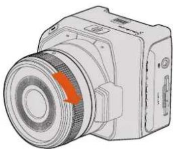
natural_image
Technical illustration of a camera module with a highlighted lens and orange arrow (no text or symbols)natural_image
Diagram of a camera module with orange rotation arrow indicating motion (no text or symbols)natural_image
Diagram of a camera module with lens and internal components, showing no text or symbolsnatural_image
Technical illustration of a camera module with lens and external connector (no text or symbols)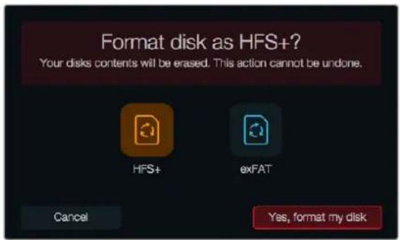
gauge
| Metric | Value | |--------|-------| | Current | 432.5 | | Range (approx) | 432.5 (approx) |natural_image
Illustration of a gray electronic device with control buttons and a red indicator button (no text or symbols)natural_image
Line drawing of a black-and-white digital camera with lens and control buttons (no text or symbols)natural_image
Line drawing of a digital camera module with control buttons and display (no text or symbols)Sortie HDMI
natural_image
Diagram of a device with a USB port and connector, showing no text or symbolsVoyant tally Blackmagic Micro Cinema Camera
natural_image
Technical illustration of a camera with red highlighted lens and inset detail (no text or symbols)Secondes :1 - 10, 20, 30, 40, 50
Minutes : 1 - 10
natural_image
Street scene with a person walking past parked bicycles under a golden sky (no visible text or symbols)natural_image
Silhouette of a person standing on a wooden surface with mountain peaks in the background (no text or symbols)natural_image
Symbol of a circular arrow with the letter 'A' inside, representing refresh or cycle (no text or numbers present)Utiliser DaVinci Resolve
natural_image
Silhouette of a human head against a blue sky background (no text or symbols)natural_image
Person sitting by a coastal cliff at sunset, overlooking the sea with hills in the background (no text or symbols visible)natural_image
Interior view of a car with driver visible through the windshield, surrounded by red pillars and ceiling structures (no text or symbols)natural_image
Modern living room interior with large windows overlooking the sea, featuring a man standing near a circular metal frame and armchairs (no visible text or symbols)Bus principal (Main bus)
natural_image
Technical illustration of a device's internal structure showing a sensor or camera module and its exploded view (no text or symbols present)natural_image
Diagram of a camera module with attached cable and connector, showing internal components and wiring (no text or symbols)natural_image
Circular portrait photo of a smiling man in a black polo shirt against a textured gray background (no text or symbols)Willkommen
CEO, Blackmagic Design
Inhaltsverzeichnis
Blackmagic Design Compact Cameras
Erste Schritte 197
natural_image
Four-panel illustration of a digital camera with orange arrows indicating rotation or adjustment (no text or symbols)natural_image
Diagram of a camera module with an orange rotation arrow indicating the process (no text or symbols present)natural_image
Technical illustration of a camera module with lens and internal components (no text or symbols)natural_image
Technical line drawing of a camera module with lens and external connector (no text or symbols)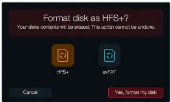
natural_image
Illustration of a handheld electronic device with control buttons and a red indicator button (no text or symbols)natural_image
Illustration of a remote control console with a play button and playback buttons (no text or symbols)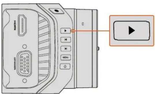
natural_image
Line drawing of a black-and-white digital camera with lens and control buttons (no text or symbols)LANC-Fernbedienung
natural_image
Line drawing of a digital camera module with labeled buttons and ports (no text or symbols beyond branding)HDMI-Ausgang
natural_image
Diagram of a device with a USB symbol and connector, showing internal components without any text or labels.natural_image
Diagram of a digital camera with an inset showing a red highlighted area on the lens (no text or symbols present)Channel 2 uses Channel 1 Input
Tally Light Brightness
natural_image
Street scene with a person walking past parked bicycles under a sunset sky (no visible text or symbols)natural_image
Silhouette of two prominent mountain peaks against a wooden background (no text or symbols)natural_image
Abstract circular arrow symbol with the letter 'A' at center, no text or numbers presentnatural_image
Silhouette of a human head against a blue sky background (no text or symbols)natural_image
Person sitting by a coastal cliff at sunset, overlooking the sea with hills in the background (no text or symbols visible)natural_image
Interior view of a car with driver's seat and dashboard, showing no visible text or symbolsnatural_image
Modern living room interior with large windows overlooking the sea, featuring a man standing near a circular metal frame and patterned sofas (no visible text or symbols)line
| Time | Volume | |------|--------| | Peak | 4.69 dB |line
| Metric | Value | | ------------ | ----- | | Gain | 0 | | Gain | -9.5 | | Gain | +7.5 | | Gain | -0.7 | | Gain | +0.3 | | Gain | -0.3 | | Gain | 0 | | Gain | -0.0 | | Gain | 0 | | Gain | -0.0 | | Gain | 0 | | Gain | -0.0 | | Gain | 0 | | Gain | -0.0 | | Gain | 0 | | Gain | -0.0 | | Gain | 0 | | Gain | -0.0 | | Gain | 0 |natural_image
Technical illustration of a device's internal structure showing a lid, housing, and mechanical components (no text or symbols)Projekteinstellungen in Final Cut Pro X
natural_image
Diagram of a camera module with cable and connector, showing internal components and wiring (no text or symbols)natural_image
Circular portrait photo of a smiling man with short hair, wearing a dark polo shirt (no text or symbols visible)Bienvenido
natural_image
Illustration of a digital camera with a circular lens and orange arrow indicating rotation (no text or symbols)
natural_image
Illustration of a digital camera with an orange scroll wheel and control buttons (no text or symbols)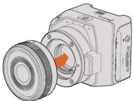
natural_image
Technical illustration of a mechanical device with a pulley and housing (no text or symbols)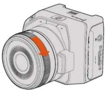
natural_image
Illustration of a camera with a red arrow indicating rotation or direction (no text or symbols present)natural_image
Diagram of a camera module with an orange rotation arrow indicating the process (no text or symbols present)natural_image
Technical illustration of a camera lens assembly with an orange arrow indicating a component (no text or symbols present)natural_image
Diagram of a digital camera with lens and external connector (no text or symbols)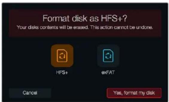
gauge
| Metric | Value | |--------|-------| | Current | 432.5 | | Peak | 432.5 |natural_image
Illustration of a handheld electronic device with control buttons and a highlighted indicator button (no text or symbols)natural_image
Line drawing of a black-and-white digital camera with lens and control buttons (no text or symbols)LANC
natural_image
Line drawing of a digital camera module with control buttons and display panel (no text or symbols)Salida HDMI
natural_image
Diagram of a device with two USB ports and a close-up view of the internal connector (no text or symbols)natural_image
Diagram of a camera with red highlighted lens and inset view showing internal components (no text or symbols)natural_image
Street scene with a person walking on a sidewalk, bicycles parked in the background, and a building in the background under a sunset sky (no visible text or symbols)natural_image
Silhouette of a mountain peak with two valleys, set against a wooden surface (no text or symbols)natural_image
Abstract circular arrow symbol with the letter 'A' at center, no text or numbers presentnatural_image
Silhouette of a human head against a blue sky background (no text or symbols)natural_image
Person sitting by a coastal cliff at sunset, overlooking the sea with hills in the background (no text or symbols visible)natural_image
Interior view of a car with a driver visible through the windshield, overlaid with a bounding box and red pillars (no text or symbols)natural_image
Modern living room interior with large windows overlooking the sea, featuring a man standing near a circular frame and furniture (no visible text or symbols)natural_image
Technical illustration of a camera module with internal components and a close-up view of the assembly (no text or symbols)natural_image
Diagram of a digital camera with attached cable and lens, showing internal components and wiring (no text or symbols)安装操作手册
Blackmagic
Design
紧凑型摄影机系列
2018年5月
中文

natural_image
Circular portrait photo of a smiling man in a black shirt against a gray background (no text or symbols)欢迎辞
natural_image
Illustration of a digital camera with a circular lens and orange accent (no text or symbols)
natural_image
Illustration of a digital camera with an orange accent and control buttons (no text or symbols)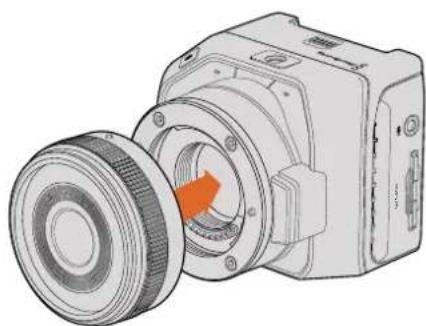
natural_image
Technical illustration of a mechanical device with a highlighted circular component and a belt drive (no text or symbols)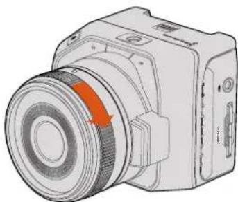
natural_image
Illustration of a camera with a red arrow indicating rotation or motion (no text or symbols present)为Blackmagic Pocket Cinema Camera和Blackmagic Micro Cinema Camera机型安装及取下MFT镜头
natural_image
Diagram of a camera module with orange rotation arrow indicating assembly (no text or symbols)为Blackmagic Pocket Cinema Camera安装电池
为Blackmagic Micro Cinema Camera安装电池并开启电源
natural_image
Technical illustration of a camera module with lens and internal components (no text or symbols)为Blackmagic Pocket Cinema Camera安装SD卡
Blackmagic Micro Cinema Camera
natural_image
Diagram of a digital camera with lens and external connector (no text or symbols)为Blackmagic Micro Cinema Camera安装SD卡
关于SD卡
选择高速SD卡
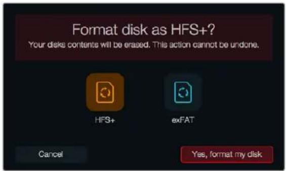
gauge
| Metric | Value | |--------|-------| | Current | 432.5 | | Peak Speed | 432.5 (MB/s) |natural_image
Illustration of a handheld device with control buttons and a red indicator light (no text or symbols)natural_image
Line drawing of a digital camera with lens and control buttons (no text or symbols)LANC遥控控制
natural_image
Line drawing of a digital camera module with control buttons and lens (no text or symbols)HDMI输出
natural_image
Diagram of a device with two USB ports and a close-up of the internal connector (no text or symbols)Blackmagic Micro Cinema Camera的Tally灯
natural_image
Diagram of a camera with red highlighted lens and inset view showing internal components (no text or symbols)Tally 灯位于Blackmagic Micro Cinema Camera镜头上方
菜单设置
Dashboard主菜单
使用屏幕键盘更改摄影机D
Tally Light Brightness (Tally 灯亮度)
LCD Overlay (LCD叠加信息)
natural_image
Street scene with a person walking past parked bicycles under a clear sky (no visible text or symbols)natural_image
Silhouette of two prominent mountain peaks against a wooden background (no text or symbols)natural_image
Symbol of a circular arrow with the letter 'A' inside, representing refresh or cycle (no text or numbers present)转场面板中包含有多种转场特效
natural_image
Silhouette of a human head against a blue sky background (no text or symbols)natural_image
Person sitting by a coastal cliff at sunset, overlooking the sea with distant hills (no text or symbols visible)natural_image
Interior view of a car with driver and window, showing dashboard and steering wheel (no visible text or symbols)natural_image
Interior view of a modern living room with large windows, high furniture, and a man standing near a glass pendant light (no visible text or symbols)六频段参量均衡器可应用到每个轨道
natural_image
Technical illustration of a camera module with internal components and a close-up view of the assembly (no text or symbols)Final Cut Pro X项目设置
natural_image
Diagram of a digital camera with attached cable and lens, showing internal components and wiring (no text or symbols)Blackmagic Pocket Cinema Camera的腕带
帮助
获得帮助
설치 및 사용 설명서
Blackmagic
Design
소형 카메라
2018년5월
한국어

natural_image
Circular portrait photo of a smiling man in a dark shirt against a gray background (no text or symbols)환영합니다.
natural_image
Illustration of a digital camera with a circular lens and orange arrow indicating rotation (no text or symbols)
natural_image
Illustration of a digital camera with an orange arrow indicating rotation (no text or symbols present)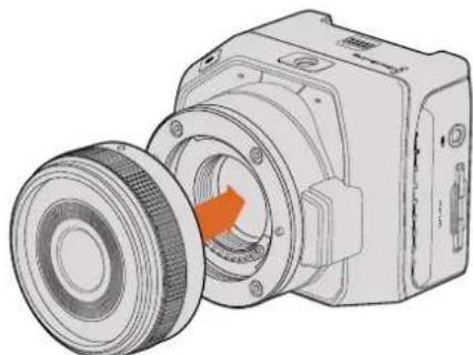
natural_image
Technical illustration of a mechanical device with a circular component and an orange arrow indicating rotation (no text or symbols present)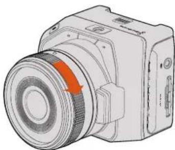
natural_image
Illustration of a camera module with a highlighted lens and orange arrow indicating rotation (no text or symbols)natural_image
Diagram of a camera module with an orange rotation arrow indicating motion (no text or symbols present)natural_image
Diagram of a camera lens assembly with an orange arrow indicating a component (no text or symbols present)natural_image
Diagram of a digital camera with lens and external connector (no text or symbols)
gauge
| Metric | Value | |--------|-------| | Current | 432.5 | | Peak | 432.5 |natural_image
Illustration of a handheld electronic device with control buttons and a highlighted red button (no text or symbols)natural_image
Line drawing of a modern digital camera with lens and control buttons (no text or symbols)LANC 원격 제어
natural_image
Line drawing of a digital camera module with control buttons and lens (no text or symbols)HDMI 출력
natural_image
Diagram of a device with two USB ports and a close-up of the internal connector (no text or symbols)natural_image
Diagram of a digital camera with an inset showing a red highlighted component (no text or symbols present)초:1 - 10, 20, 30, 40, 50
분:1-10
탈리 밞기 (Tally Light Brightness)
natural_image
Street scene with a person walking past parked bicycles under a golden sky (no visible text or symbols)natural_image
Silhouette of two prominent mountain peaks against a wooden background (no text or symbols)natural_image
Abstract circular arrow symbol with the letter 'A' at the center, no text or numbers present.natural_image
Silhouette of a human head against a blue sky background (no text or symbols)natural_image
Person sitting by a coastal cliff at sunset, overlooking the sea with hills in the background (no text or symbols visible)natural_image
Side view of a black car with a white bounding box on the windshield, inside a parking garage (no visible text or symbols)natural_image
Interior view of a modern living room with large windows, high furniture, and a person standing near a circular frame (no visible text or symbols)line
| Time (s) | Volume (dB) | | -------- | ----------- | | Peak | 4.69 |natural_image
Technical illustration of a device's internal structure showing a lens assembly and a close-up view of the component (no text or symbols present)natural_image
Diagram of a digital camera with attached cable and lens, showing internal wiring (no text or symbols)Blackmagic Pocket Cinema Camera 손목 끈
지원
지원 받기
natural_image
Circular portrait photo of a smiling man in a dark shirt against a gray background (no text or symbols)Добро пожаловать!
natural_image
Diagram of a camera module with an orange rotation arrow indicating the operation (no text or symbols present)natural_image
Technical illustration of a camera module with lens and internal components (no text or symbols)Установка SD-карты в Blackmagic Pocket Cinema Camera
Blackmagic Micro Cinema Camera
natural_image
Technical illustration of a camera module with lens and external connector (no text or symbols)Установка SD-карты в Blackmagic Micro Cinema Camera
Работа с SD-картами

gauge
| Metric | Value | |--------|-------| | Current | 432.5 | | Peak Speed | 432.5 (approx) | | Range (min) | 0 to 432.5 (approx) | | Color Scale | Blue to Red (approx) |natural_image
Illustration of a handheld device with control buttons and a red button, no text or symbols presentnatural_image
Line drawing of a black-and-white digital camera with lens and control buttons (no text or symbols)natural_image
Line drawing of a digital camera with control buttons and ports (no text or symbols)Выход HDMI
natural_image
Diagram of a device with a USB port and an icon showing a USB symbol (no text or labels present)Порт USB на нижней панели Micro Cinema Camera
natural_image
Diagram of a camera with red highlighted lens and magnified detail view (no text or symbols)natural_image
Street scene with a person walking past parked bicycles under a golden hour, no visible text or symbolsnatural_image
Silhouette of two mountain peaks against a wooden background (no text or symbols)natural_image
Abstract circular arrow symbol with the letter 'A' at center, no text or numbers presentline
| Time | Red Line Value | Green Line Value | Blue Line Value | |------|----------------|------------------|-----------------| | 0 | 0 | 0 | 0 | | 1 | 705 | 0 | 0 | | 2 | 512 | 0 | 0 | | 3 | 640 | 0 | 0 | | 4 | 512 | 640 | 0 | | 5 | 0 | 0 | 640 | | 6 | 0 | 0 | 640 | | 7 | 0 | 0 | 640 | | 8 | 0 | 0 | 640 | | 9 | 0 | 0 | 640 | | 10 | 0 | 0 | 640 | | 11 | 0 | 0 | 640 | | 12 | 0 | 0 | 640 | | 13 | 0 | 0 | 640 | | 14 | 0 | 0 | 640 | | 15 | 0 | 0 | 640 | | 16 | 0 | 0 | 640 | | 17 | 0 | 0 | 640 | | 18 | 0 | 0 | 640 | | 19 | 0 | 0 | 640 | | 20 | 0 | 0 | 640 | | 21 | 0 | 0 | 640 | | 22 | 0 | 0 | 640 | | 23 | 0 | 0 | 640 | | 24 | 0 | 0 | 640 | | 25 | 0 | 0 | 640 | | 26 | 0 | 0 | 640 | | 27 | 0 | 0 | 640 | | 28 | 0 | 0 | 640 | | 29 | 0 | 0 | 640 | | 30 | 0 | 0 | 640 | | 31 | 0 | 0 | 640 | | 32 | 0 | 0 | 640 | | 33 | 0 | 0 | 640 | | 34 | 0 | 0 | 640 | | 35 | 0 | 0 | 640 | | 36 | 0 | 0 | 640 | | 37 | 0 | 0 | 640 | | 38 | 0 | 0 | 640 | | 39 | 0 | 0 | 640 | | 40 | 0 | 0 | 640 | | 41 | 0 | 0 | 640 | | 42 | 0 | 0 | 640 | | 43 | 0 | 0 | 640 | | 44 | 0 | 0 | 640 | | 45 | 0 | 0 | 640 | | 46 | 0 | 0 | 640 | | 47 | 0 | 0 | 640 | | 48 | 0 | 0 | 640 | | 49 | 0 | 0 | 640 | | 50 | 0 | 0 | 640 | | ... (approximate values) for the rightmost curve are not provided in the code. The actual values may vary due to the use of random number generation. The numbers in the legend are estimated based on the data source and the variable names. There is no label for the data series. The chart type is a line graph.natural_image
Silhouette of a human head against a blue sky background (no text or symbols)natural_image
Person sitting on a coastal cliff overlooking the sea at sunset, with hills in the background (no text or symbols visible)natural_image
Interior view of a car with driver visible through the windshield, enclosed in a parking garage (no text or symbols)natural_image
Interior view of a modern living room with large windows, high-rise furniture, and a person standing near a circular metal frame (no visible text or symbols)natural_image
Technical illustration of a device's internal structure showing a lens assembly and a close-up view of the component (no text or symbols present)natural_image
Diagram of a digital camera with cable and connector, showing internal components and wiring (no text or symbols)natural_image
Circular portrait photo of a smiling man in a black shirt against a textured gray background (no text or symbols)Micro Cinema Camera Expansion Cable 530
Spie tally 531
natural_image
Illustration of a digital camera with a circular lens and orange arrow indicating rotation (no text or symbols)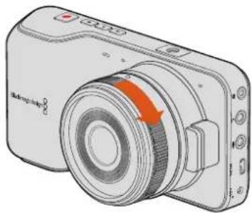
natural_image
Illustration of a digital camera with an orange arrow indicating rotation (no text or symbols present)
natural_image
Technical illustration of a mechanical device with a circular component and orange arrow indicating rotation (no text or symbols)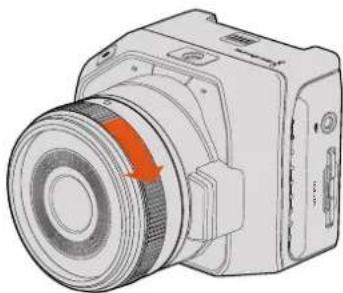
natural_image
Illustration of a camera module with a red arrow indicating rotation or direction (no text or symbols present)natural_image
Diagram of a camera module with an orange rotation arrow indicating the operation (no text or symbols present)natural_image
Technical illustration of a camera module with lens and internal components (no text or symbols)natural_image
Technical line drawing of a camera module with lens and external connector (no text or symbols)
natural_image
Illustration of a handheld electronic device with control buttons and a highlighted indicator button (no text or symbols)natural_image
Line drawing of a black-and-white photo camera with lens and control buttons (no text or symbols)Controllo remoto LANC
natural_image
Line drawing of a digital camera module with control buttons and ports (no text or symbols)Uscita HDMI
natural_image
Diagram of a device with a USB port and connector, showing no text or symbolsBlackmagic Micro Cinema Camera Expansion Cable
natural_image
Diagram of a camera with red highlighted lens and inset view showing internal components (no text or symbols)Volume cuffie e speaker
Secondi 1–10, 20, 30, 40, 50
Minuti 1 – 10
natural_image
Street scene with a person walking past parked bicycles under a clear sky (no visible text or symbols)natural_image
Silhouette of a mountain peak against a wooden surface (no text or symbols)natural_image
Abstract circular arrow symbol with the letter 'A' at the center, no text or numerical labels present.line
| Time | Red Line | Green Line | Blue Line | |------|----------|------------|-----------| | 0 | 0 | 0 | 0 | | 1 | 896 | 0 | 0 | | 2 | 512 | 640 | 0 | | 3 | 0 | 0 | 640 | | 4 | 0 | 0 | 640 | | 5 | 0 | 0 | 640 | | 6 | 0 | 0 | 640 | | 7 | 0 | 0 | 640 | | 8 | 0 | 0 | 640 | | 9 | 0 | 0 | 640 | | 10 | 0 | 0 | 640 | | 11 | 0 | 0 | 640 | | 12 | 0 | 0 | 640 | | 13 | 0 | 0 | 640 | | 14 | 0 | 0 | 640 | | 15 | 0 | 0 | 640 | | 16 | 0 | 0 | 640 | | 17 | 0 | 0 | 640 | | 18 | 0 | 0 | 640 | | 19 | 0 | 0 | 640 | | 20 | 0 | 0 | 640 | | 21 | 0 | 0 | 640 | | 22 | 0 | 0 | 640 | | 23 | 0 | 0 | 640 | | 24 | 0 | 0 | 640 | | 25 | 0 | 0 | 640 | | 26 | 0 | 0 | 640 | | 27 | 0 | 0 | 640 | | 28 | 0 | 0 | 640 | | 29 | 0 | 0 | 640 | | 30 | 0 | 0 | 640 | | 31 | 0 | 0 | 640 | | 32 | 0 | 0 | 640 | | 33 | 0 | 0 | 640 | | 34 | 0 | 0 | 640 | | 35 | 0 | 0 | 640 | | 36 | 0 | 0 | 640 | | 37 | 0 | 0 | 640 | | 38 | 0 | 0 | 640 | | 39 | 0 | 0 | 640 | | 40 | 0 | 0 | 640 | | 41 | 0 | 0 | 640 | | 42 | 0 | 0 | 640 | | 43 | 0 | 0 | 640 | | 44 | 0 | 0 | 640 | | 45 | 0 | 0 | 640 | | 46 | 0 | 0 | 640 | | 47 | 0 | 0 | 640 | | 48 | 0 | 0 | 640 | | 49 | 0 | 0 | 640 | | 50 | 0 | 0 | 640 | | ... (approximate values) for the remainder of the timeline are not provided in the code. The actual values may vary due to the use of random number generation. The numbers in the data table are estimated based on the code's output.natural_image
Silhouette of a human head against a blue sky background (no text or symbols)natural_image
Person sitting by a coastal cliff at sunset, overlooking the sea with hills in the background (no text or symbols visible)natural_image
Interior view of a car with a driver visible through the window, no text or symbols present.natural_image
Interior view of a modern living room with large windows, a person standing near a circular metal frame, and no visible text or symbols.natural_image
Technical illustration of a device's internal components, showing a cylindrical component and a close-up view of its internal structure (no text or symbols present)natural_image
Diagram of a camera module with cable and connector, showing internal components and wiring (no text or symbols)natural_image
Circular portrait photo of a smiling man in a black polo shirt against a textured gray background (no text or symbols)Bem-vindo
natural_image
Illustration of a digital camera with a highlighted lens and orange arrow (no text or symbols)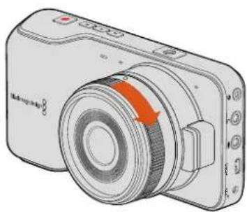
natural_image
Illustration of a digital camera with an orange arrow indicating rotation (no text or symbols present)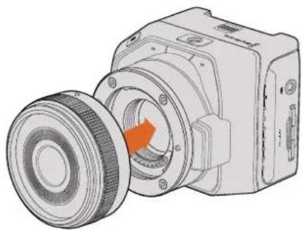
natural_image
Technical illustration of a mechanical device with a circular component and orange arrow indicating rotation (no text or symbols)
natural_image
Illustration of a digital camera with an orange circular component and control buttons (no text or symbols)natural_image
Diagram of a camera module with an orange rotation arrow indicating the assembly process (no text or symbols present)Inserindo a bateria na Blackmagic Pocket Cinema Camera.
natural_image
Diagram of a camera module with lens and internal components, showing no text or symbolsnatural_image
Technical line drawing of a camera module with an orange arrow pointing to a component (no text or symbols present)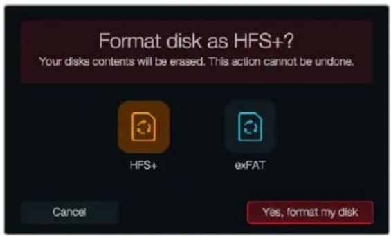
natural_image
Illustration of a handheld electronic device with control buttons and a red indicator button (no text or symbols)natural_image
Line drawing of a black-and-white digital camera with lens and control buttons (no text or symbols)Controle Remoto LANC
natural_image
Line drawing of a digital camera module with control buttons and ports (no text or symbols)Saída HDMI
natural_image
Diagram of a device with a USB symbol and an inset showing the same symbol (no text or labels present)natural_image
Diagram of a digital camera with an inset showing a red highlighted component (no text or symbols present)Hora (16:31pm - 24hrs)
Número do Clipe
natural_image
Street scene with a person walking past parked bicycles under a golden hour, no visible text or symbolsnatural_image
Silhouette of two prominent mountain peaks against a wooden background (no text or symbols)natural_image
Abstract circular arrow symbol with the letter 'A' at center, no text or numbers presentUsar o DaVinci Resolve
Corrigir as Cores dos Seus Clipes
natural_image
Silhouette of a human head against a blue sky background (no text or symbols)natural_image
Person sitting by a coastal cliff at sunset, overlooking the sea with hills in the background (no text or symbols visible)natural_image
Interior view of a car with a person visible through the window frame (no text or symbols)natural_image
Interior view of a modern living room with large windows, a person standing near a circular metal frame, and no visible text or symbols.natural_image
Technical illustration of a camera module assembly with an inset close-up showing internal components (no text or symbols)Usar Final Cut Pro X
Usar Avid Media Composer
natural_image
Diagram of a camera module with cable and connector, showing internal components and wiring (no text or symbols)Correia de Pulso da Blackmagic Pocket Cinema Camera.
Ajuda
Obtendo Ajuda
natural_image
Circular portrait photo of a smiling man in a black polo shirt against a textured gray background (no text or symbols)Hoş Geldiniz
CEO Blackmagic Design
İçindekiler
Blackmagic Design Kompakt Kameraları
Başlarken
Camera Tally Lambasi 659
Menü Ayarları 660
Dashboard (Gösterge Paneli) 660
Kamera Ayarları 660
Ses Ayarları 663
Kayıt Ayarları 665
natural_image
Illustration of a digital camera with an orange arrow pointing to the lens (no text or symbols present)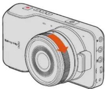
natural_image
Illustration of a digital camera with an orange arrow indicating rotation (no text or symbols present)
natural_image
Technical illustration of a mechanical device with a circular component and an orange arrow indicating rotation (no text or symbols present)
natural_image
Illustration of a digital camera with an orange circular component and control buttons (no text or symbols)natural_image
Diagram of a camera module with an orange rotation arrow indicating clockwise motion (no text or symbols)natural_image
Technical illustration of a camera module with lens and internal components (no text or symbols)natural_image
Technical line drawing of a camera module with lens and external connector (no text or symbols)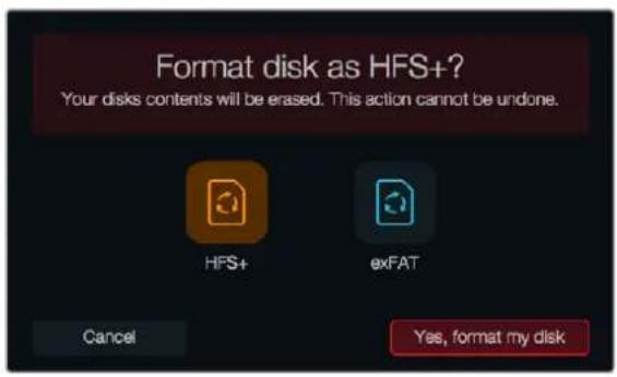
natural_image
Illustration of a handheld electronic device with control buttons and a red button (no text or symbols)natural_image
Line drawing of a black-and-white digital camera with lens and control buttons (no text or symbols)LANC Uzaktan Kontrol
natural_image
Line drawing of a digital camera module with control buttons and lens (no text or symbols)HDMI ÇIKIŞI
natural_image
Diagram of a device with a USB symbol and an inset showing the same symbol (no text or labels present)Blackmagic Micro Cinema Camera Tally Lambasi
natural_image
Diagram of a camera with red highlighted lens and control panel, showing no text or symbolsTally lambasi, Blackmagic Micro Cinema Camera lensinin üzerindedir
Menü Ayarları
Dashboard (Gösterge Paneli)
Kare Hizi (Frame Rate)
Sanlyeler: 1 - 10, 20, 30, 40, 50
Dakikalar: 1 - 10
Time (16:31pm - 24hrs)
Clip Number
Ekran Ayarları
natural_image
Street scene with a person walking past bicycle lanes, no visible text or symbolsnatural_image
Silhouette of two white mountain peaks on a wooden surface, with a blurred human figure in the background (no text or symbols)natural_image
Abstract circular arrow symbol with the letter 'A' at center, no text or numbers presentnatural_image
Silhouette of a human head against a blue sky background (no text or symbols)natural_image
Person standing by a coastal cliff at sunset, overlooking the sea with distant hills (no text or symbols visible)natural_image
Interior view of a car with a driver visible, enclosed by a bounding box (no text or symbols)natural_image
Modern living room interior with large windows overlooking the sea, featuring a man standing near a circular metal frame and armchairs (no visible text or symbols)natural_image
Technical illustration of a mechanical device with internal components and a close-up view of the assembly (no text or symbols)Final Cut Pro X proje ayarlan
natural_image
Diagram of a camera module with cable and connector, showing internal components and wiring (no text or symbols)Blackmagic Pocket Cinema Camera bilek askisi