Studio Camera 4K Pro - Camera Blackmagic Design - Free user manual and instructions
Find the device manual for free Studio Camera 4K Pro Blackmagic Design in PDF.
| Product Type | Professional Studio Camera |
| Brand | Blackmagic Design |
| Model | Studio Camera 4K Pro |
| Sensor | 4/3" CMOS Sensor (Micro Four Thirds) |
| Maximum Video Resolution | 3840 x 2160 pixels (Ultra HD 4K) |
| Maximum Frame Rate | 60 fps in 4K, 120 fps in 1080p |
| Lens Mount | Micro Four Thirds (MFT) |
| Built-in Display | 7" LCD with Built-in Viewfinder |
| Connectivity | HDMI, SDI, USB-C, Ethernet, XLR Audio |
| Recording | Blackmagic RAW, ProRes, DNxHD Codecs |
| Storage | SD UHS-II Cards and External USB-C Recorder |
| Power | 12-32V DC (AC adapter included), optional battery |
| Dimensions (L x H x D) | 204 x 126 x 149 mm |
| Weight | Approximately 2.3 kg (without lens or battery) |
| Maintenance and Cleaning | Clean the exterior with a soft cloth; use a blower for the sensor |
| Safety | Do not expose to moisture; ensure adequate ventilation |
| Spare Parts and Repairability | Standard Micro Four Thirds lenses and accessories; repair by authorized center |
| General Information | Camera designed for live production and studio |
| Operating Temperature | 0°C to 40°C |
| Control Interface | Physical control panel and Blackmagic Camera app |
Frequently Asked Questions - Studio Camera 4K Pro Blackmagic Design
User questions about Studio Camera 4K Pro Blackmagic Design
0 question about this device. Answer the ones you know or ask your own.
Ask a new question about this device
Download the instructions for your Camera in PDF format for free! Find your manual Studio Camera 4K Pro - Blackmagic Design and take your electronic device back in hand. On this page are published all the documents necessary for the use of your device. Studio Camera 4K Pro by Blackmagic Design.
USER MANUAL Studio Camera 4K Pro Blackmagic Design
To go directly to your preferred language, simply click on the hyperlinks listed in the contents below.
English 3.
日本語 104
Français 206
Deutsch.308
Espanol 410
中文 512
614
Pycckn.716
Italiano 818
Portugues 920
Türkce 1022

Welcome
Thank you for purchasing a Blackmagic Studio Camera!
Blackmagic Studio Cameras have the same features as large studio cameras, miniaturized into a single compact and portable design.
With increased dynamic range and Blackmagic Design color science, the cameras can handle extremely difficult lighting conditions while producing cinematic looking images. The dual gain sensor supports ISO up to 25,600 so you can create amazing images even in dimly lit venues.
Advanced features include talkback, tally, camera control, built in color corrector, Blackmagic RAW recording to USB disks and much more! You can even add a focus and zoom demand for lens control!
We hope you use your new camera for some amazing live productions and produce some fantastic looking work! We are extremely excited to see what creative work you produce!

Grant Petty
CEO Blackmagic Design
Contents
Which Studio Camera are you using? 5
Getting Started 5
Attaching a Lens 6
Plugging in Power 7
Turning Your Camera On 7
Setting the Frame Rate and Resolution 8
Connecting to an ATEM switcher 9
Connecting a Talkback Headset 10
Setting the ATEM Camera ID 11
Checking your Setup 11
Studio Camera Connections 13
Left Panel 13
Right Panel 14
5 Pin XLR Talkback Connector
Pinout Diagram 15
Using Studio Camera Controls 15
Touchscreen Controls 18
Changing Settings using the Head up Display 18
Head up Display Settings 19
Menu Settings 38
Record Settings 39
Blackmagic RAW 40
Recording to Blackmagic RAW 40
Record Duration 43
File Naming Convention 47
Monitor Settings 47
Audio Settings 56
Setup Settings 59
Presets 66
LUTs 68
Using the Sun Hood 71
Blackmagic Zoom and Focus Demands 72
Connecting and Attaching to your
Camera 73
Using Blackmagic Focus Demand 75
Using Blackmagic Zoom Demand 76
Blackmagic Camera Setup 78
How to Update your Camera's Internal Software 78
Using ATEM Software Control 79
Camera Control 79
Using Camera Control 79
DaVinci Resolve Primary Color Corrector 83
Developer Information 86
Blackmagic SDI Camera Control Protocol 86
Example Protocol Packets 95
Blackmagic Embedded Tally Control Protocol 96
Connecting Tally using the Blackmagic 3G-SDI Shield for Arduino 98
Help 100
Regulatory Notices 101
Safety Information 102
Warranty 103
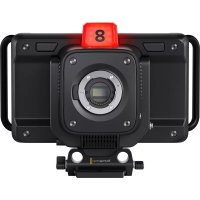
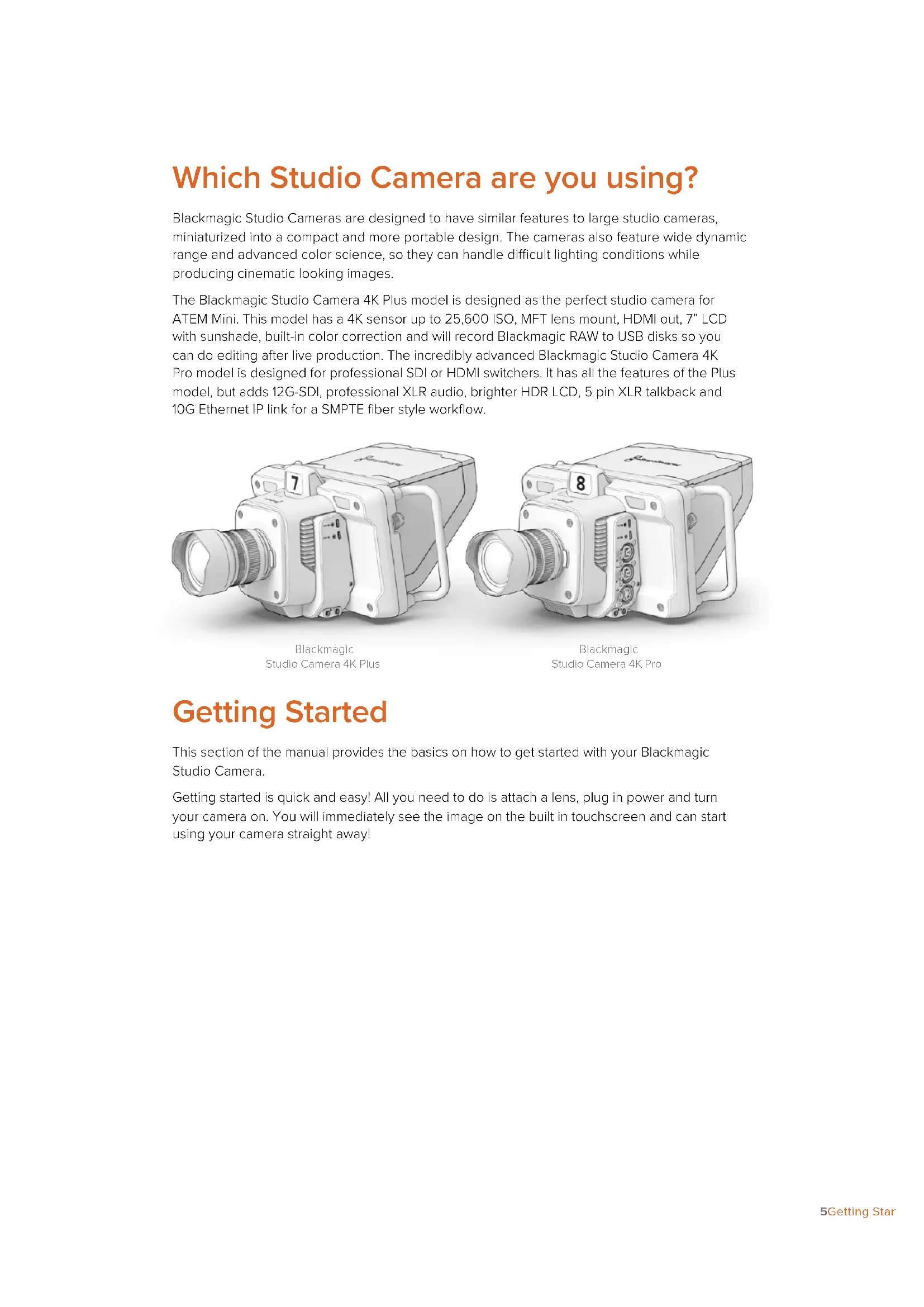
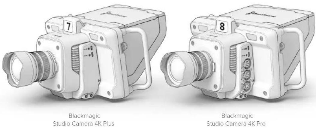
Which Studio Camera are you using?
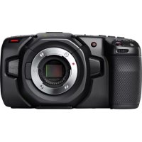
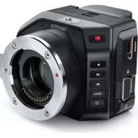
Blackmagic Studio Cameras are designed to have similar features to large studio cameras, miniaturized into a compact and more portable design. The cameras also feature wide dynamic range and advanced color science, so they can handle difficult lighting conditions while producing cinematic looking images.
The Blackmagic Studio Camera 4K Plus model is designed as the perfect studio camera for ATEM Mini. This model has a 4K sensor up to 25,600 ISO, MFT lens mount, HDMI out, 7" LCD with sunshade, built-in color correction and will record Blackmagic RAW to USB disks so you can do editing after live production. The incredibly advanced Blackmagic Studio Camera 4K Pro model is designed for professional SDI or HDMI switchers. It has all the features of the Plus model, but adds 12G-SDI, professional XLR audio, brighter HDR LCD, 5 pin XLR talkback and 10G Ethernet IP link for a SMPTE fiber style workflow.
Getting Started
This section of the manual provides the basics on how to get started with your Blackmagic Studio Camera.
Getting started is quick and easy! All you need to do is attach a lens, plug in power and turn your camera on. You will immediately see the image on the built in touchscreen and can start using your camera straight away!
Attaching a Lens
The first step to getting started is to remove the protective dust cap and attach a lens. To remove the dust cap from the lens mount, hold down the lens release button and rotate the cap counterclockwise until released. We recommend always turning off your Blackmagic camera prior to attaching or removing a lens.
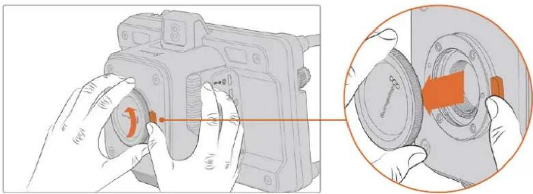
Press the lens release button and rotate the dust cap counterclockwise until it is released from the mount
Blackmagic Studio Camera's have MFT lens mounts for attaching Micro Four Thirds lenses.
To attach a lens:
1 Align the dot on your lens with the dot on the camera mount. Many lenses have a corresponding indicator which may be a coloured dot or similar marker.
2 Gently push the lens's mount flat against the camera's lens mount and rotate the lens clockwise until it locks into place.

Place the rear of the lens against the mount and rotate clockwise until it locks into place
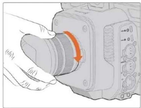
To remove the lens, hold down the lens release button and rotate the lens counterclockwise until its indicator reaches the 12 o'clock position. The lens will now be released and you can gently remove it from the mount.
NOTE It's important to mention that when no lens is attached to the camera, the lens mount is exposed to dust and other debris so you should keep the dust cap on whenever possible.
Plugging in Power
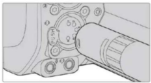
Blackmagic Studio Camera 4K Plus and the Blackmagic Studio Camera 4K Pro have 12V locking power connectors. After plugging in the connector, secure it to the camera by tightening the locking ring.
The 4 pin XLR connector lets you plug in broadcast style power supplies like the URSA 12V power adapter. When both power connectors are being used, the 4 pin XLR input provides redundancy with the small locking connector providing primary power.
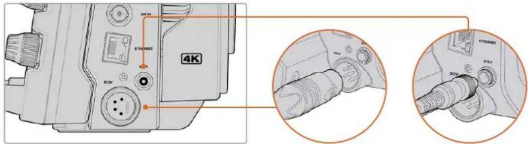
On Blackmagic Studio Camera 4K Pro, both power inputs can be connected simultaneously for redundancy
TIP Blackmagic Studio Cameras have power inputs that are rated for a voltage range of 12-18V so you can use standard 14V batteries or 14V block batteries. You can connect these batteries to your camera using either the small barrel connector or the large 4-pin XLR input on Blackmagic Studio Camera 4K Pro.
Turning Your Camera On
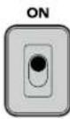
Switch the power button to the 'ON' position. The live camera image will appear on the touchscreen and buttons will illuminate. To turn the camera off, set the switch to the 'OFF' position.
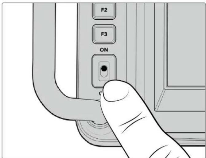
Set the power switch to 'ON' to turn on your camera.
Setting the Frame Rate and Resolution
With a lens attached and the camera turned on, the next step is to set the video format for the HDMI or SDI output. This is the video standard and frame rate you will be sending to destination equipment such as an ATEM switcher, a monitor, or HyperDeck disk recorder.
To set the frame rate:
1 Tap the frames per second icon marked FPS in the LCD status display. This will open the frame rate settings using the touchscreen head up display.
2 Tap the arrows or drag the slider to set the frame rate.
3 Tap outside the setting to confirm and close the head up display.
To set the output standard:
1 Tap the menu settings icon at the top right corner of the touchscreen. This opens all menu settings for your camera.
2 Tap the 'monitor' menu tab.
3 Tap on the right arrow to select page 2 of the monitor settings and select the HDMI or SDI output.
4 At the bottom of the settings page, you will see the output video standard. Select 2160p for Ultra HD, or 1080p for HD.
If you are connected to an ATEM switcher via HDMI, your camera's HDMI connector will automatically detect if the standard should be 1080p and set it accordingly.

Use page 2 of the monitor settings to set the video standard for the HDMI or SDI output
NOTE When recording to a USB flash Disk connected to your camera's USB port, the recording standard is always Ultra HD. This means you can still record a full resolution Ultra HD master even if you are sending your switcher an HD feed.
Connecting to an ATEM switcher
Connecting to an ATEM switcher lets you switch multiple studio cameras in your live production and control them using the switcher or ATEM Software Control. Tally signals are sent back to your camera so your camera's tally light illuminates when it is switched on air.
Connecting via HDMI
Plug your Blackmagic Studio Camera's HDMI output into the corresponding HDMI input on the ATEM switcher, such as ATEM Mini. We recommend matching your cameras with their corresponding input number. For example, camera 1 to input 1 and camera 2 to input 2.
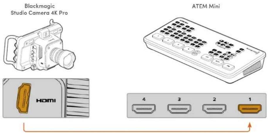
Connect your studio camera to ATEM Mini's HDMI input 1
When connected via HDMI, all tally and camera control data is sent back to your camera using the same HDMI cable.
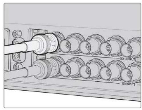
Connecting via SDI
Plug your Blackmagic Studio Camera's SDI output into the corresponding SDI input on the ATEM switcher, for example ATEM Television Studio Pro 4K.
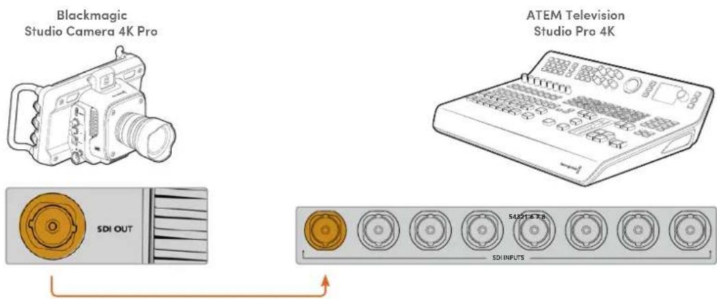
When connected via SDI, the tally and camera control data is sent back to your camera using a separate SDI program return feed. Keep reading for more information.
NOTE On ATEM Television Studio HD and ATEM Television Studio HD Pro models that have both HDMI and SDI inputs, the first SDI input is actually input 5, so you may need to set your studio camera ID to 5 for tally to work when input 5 is selected on the switcher. More information on changing the ATEM camera ID is provided later in this section.
Connecting the Program Return Feed
The program return feed lets you monitor the program output from your switcher on your studio camera's LCD. The program output also contains tally, talkback, camera control data, plus timecode and reference genlock signals.
To connect the program return feed, connect any of the ATEM switcher's SDI outputs to your studio camera's SDI input. If there is not enough program outputs, you can use any of the auxiliary outputs. Some ATEM switchers have extra program outputs to help ensure you have enough outputs for multiple cameras. On ATEM switchers such as ATEM Constellation 8K, program return can be set to any of the switcher's outputs.
Connect the switcher's SDI output to your camera's SDI input
You can also use a Blackmagic Mini Converter SDI Distribution to feed the program output to more cameras.
NOTE All outputs carry camera control data except for the multiview and any down converted outputs.
Connecting a Talkback Headset
Connect a professional broadcast headset into the 5 pin XLR connector on your Blackmagic Studio Camera 4K Pro's side panel. Consumer headsets that are commonly used on smartphones can also be used via the 3.5mm headset connector.
Connecting talkback lets you communicate with the switcher operator. Talkback audio is embedded into channels 15 and 16 of the SDI signal.
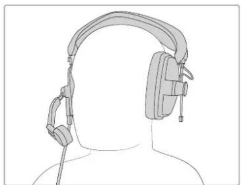

You can use common 3.5mm TRRS phone headsets that have a built in microphone via the 3.5mm jack, or use a 5 pin XLR talkback headset on the Blackmagic Studio Camera 4K Pro
Setting the ATEM Camera ID
The ATEM camera ID is a setting in your camera's menu settings that determines which SDI input your studio camera is connected to on the ATEM switcher. When the camera ID corresponds to the switcher's input number, your camera will detect tally data for that input and the tally light will work correctly on your camera.
When connected to an ATEM switcher via HDMI, you don't need to worry about setting the camera ID as the switcher can detect the input each camera is connected to and assign tally data accordingly.
For more information on changing the ATEM camera ID, refer to the 'menu settings' section.
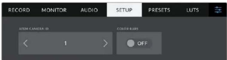
Change the ATEM camera ID using your studio camera's 'setup' settings
Checking your Setup
Now that everything is plugged in and ATEM Camera IDs are correct, you can check that everything is working.
On Blackmagic Studio Camera 4K Pro, a fast way to check is to press and hold the program button marked PGM on your camera, then switch color bars to the program output on your ATEM switcher. If you see color bars on your camera, you know the program output is working properly with your camera.
You can also lock the program view on the screen by double pressing the button. Press again to return to your camera's live image.
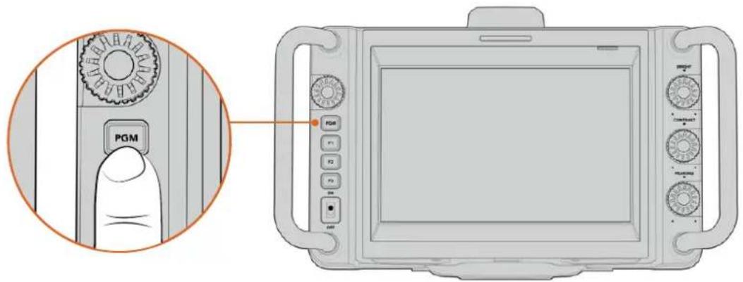
Press and hold the program button marked PGM to monitor the switcher's program output
To check that tally is working, switch camera 1 to the program output. The tally light on your studio camera should now illuminate. If not, double check your ATEM camera ID is set to the corresponding input on the switcher.
Your camera is now successfully connected to the ATEM switcher.

When your studio camera is switched to the program output, the tally light will illuminate
Recording Blackmagic RAW to USB
Finally, if you want to record to Blackmagic RAW on your camera, all you need to do is plug a USB-C flash disk formatted to Mac OS Extended or exFAT into your camera's USB connector and tap the record button on the touchscreen! Press again to stop recording.

When recording, the record button displays red
TIP When connected to an ATEM Mini Pro or Extreme model switcher, you can also trigger recording on all cameras from the switcher.
That's all there is to getting started! Keep reading this manual for more comprehensive information about all the controls and settings on your Blackmagic Studio Camera.
Studio Camera Connections
This section contains details about all the connections on your Blackmagic Studio Camera 4K Plus or 4K Pro.
Left Panel
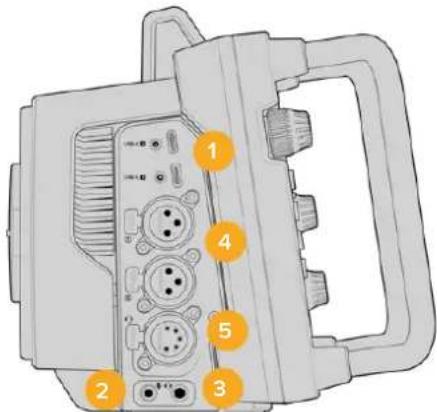
1 Locking USB
The two USB-C expansion ports allow for direct local recording onto USB-C flash disks and used for connecting Blackmagic Zoom and Focus Demands. Port A is also used for updating the camera's internal software.
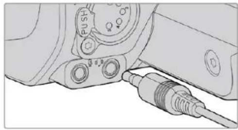
2 3.5mm Microphone Jack
Connect a microphone to your camera's 3.5mm stereo connector. Mic and line level audio are supported. The microphone level audio is lower than the line level, so if you are connecting a microphone to the camera and have line level selected, you will find the levels are too low. The microphone input also accepts SMPTE compliant LTC timecode from an external source on the left channel. Valid timecode will be detected automatically, and embedded in your video file as timecode metadata. We recommend sending LTC timecode via a line level output, especially if you are not recording timecode as an audio track.
3 3.5mm Headphone Jack
Monitor audio by plugging headphones into the 3.5mm stereo headphones jack.
4 XLR Audio In
Use the two balanced XLR inputs to plug in external analog audio from professional equipment such as audio mixers, PA systems or external microphones. The XLR connectors supply 48V phantom power so you can use microphones that aren't self powered. Refer to the 'settings' section for more information on phantom power.
5 5-Pin XLR Talkback
Plug a broadcast headset into the 5 pin XLR connector. Using a broadcast headset lets you communicate with the switcher operator. A pinout diagram is provided later in this section.
Right Panel
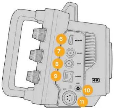
6 HDMI Output
The full size HDMI connector supports 10-bit 4:2:2 2160p Ultra HD video up to 60 frames per second with support for two channels of embedded audio. Use the touchscreen menu to set a clean feed or include overlays on the output.
You can use the HDMI port to connect to an external monitor, disk recorder or ATEM switcher. HDMI 2.0 cables are recommended if outputting Ultra HD footage.
NOTE When connecting via HDMI to an ATEM Mini, your camera's HDMI output standard will be automatically set to HD. This also applies when connecting to HD equipment such as HD monitors and HD HyperDeck disk recorders.
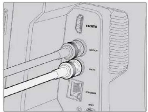
7 SDI Out
The 12G-SDI out connector on Blackmagic Studio Camera 4K Pro connects video to professional SDI video equipment such as an ATEM switcher or HyperDeck disk recorder.
8 SDI In
The 12G-SDI input on Blackmagic Studio Camera 4K Pro is used to connect the program return feed from an SDI switcher.
9 Ethernet PoE
Blackmagic Studio Camera 4K Pro features a 10G Ethernet port with PoE. To power the camera through this port, an advanced high power PoE power supply such as the Blackmagic Studio Converter or a PoE type 4 power supply is required.
10 Locking Power Input
The 12-18 Volt DC locking power connector accepts the AC power supply that is provided with your camera. The locking ring prevents accidental disconnection. You can also use this connector to plug in a battery power supply if AC power is not available.
11 4 pin XLR Power Input
Blackmagic Studio Camera 4K Pro provides a 12 to 18 Volt 4 pin male XLR connector for plugging in a redundant power supply from external sources such as the URSA 4 pin AC to 12V DC power supply or portable batteries.
5 Pin XLR Talkback Connector Pinout Diagram
| External views | Pins | Signal | I/O | Description |
| 5 pin XLR 'headset' connector | 1 Intercom MIC (Y) GND The intercom | mic input supports | ||
| 2 Intercom MIC (X) In | electret condenser mics and dynamic mics, which can be balanced or unbalanced. Pin 1 is the mic signal common, and pin 2 is the mic signal input for both types. With electret mics, a DC bias supply is also output via the same mic signal input pin. | |||
| 3 GND GND GND | ||||
| 4 Intercom left Out | ||||
| 5 Intercom right Out | ||||
Using Studio Camera Controls
Your Blackmagic Studio Camera features a large, bright 7" LCD touchscreen so you can monitor the live image, plus change settings directly from the LCD. Simply press the onscreen menu button to access the menus and change settings using tap and swipe gestures.
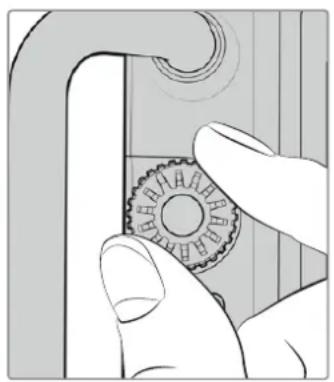
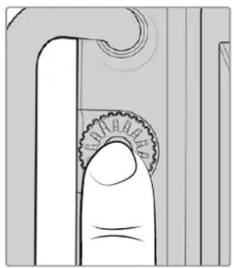
Dials on the right side let you change screen brightness and contrast as well as focus peaking sensitivity.
The settings dial on the left side lets you adjust the aperture on compatible micro four thirds lenses, plus change settings and adjust parameters in combination with the head up display.
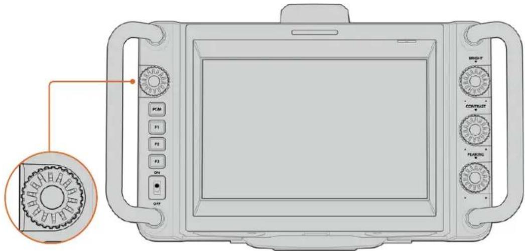
Settings Dial
Rotate the dial counterclockwise to open the iris and clockwise to close.
The settings dial is also used to adjust white balance, shutter speed and gain settings when they are selected on the camera's head up display.
When the 'focus zoom' function is enabled, the image is magnified for you to see greater detail. You can adjust the magnification by turning the dial. Pressing and rotating the dial lets you reposition the cropped image.
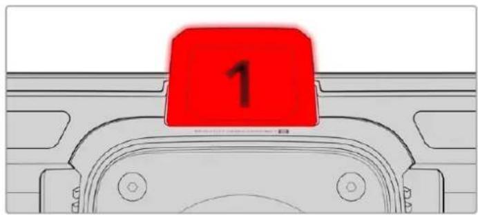
Tally Light
Your studio camera has a small tally indicator on the LCD, plus a large tally light on the top panel. When your camera is connected to an ATEM switcher, the tally light lets the talent and camera operator know which camera is on air, which camera is about to go live and if the camera is recording.
When your camera is on air, the tally indicators illuminate red, green when switched to the preview output and orange when ISO recording.
Your camera also features clip-on transparent camera numbers that attach to the tally light, making it easy for talent to see camera numbers up to 20 feet away.
Camera is switched to the program output and is live on air.
Camera is switched to the preview output and about to go on air.
Recording to a USB-C flash disk.

NOTE When the camera is not connected to a switcher the tally light will illuminate red as a simple record tally indicator.
Tally Light Number Template
Editable PDF's are provided in the software installer allowing you to edit and print out your own custom tally numbers to match ones provided. After installing the Blackmagic cameras software these can be found on a Mac in the Application > Blackmagic Cameras > Documents folder and on a PC in the Blackmagic Design > Documents folder.
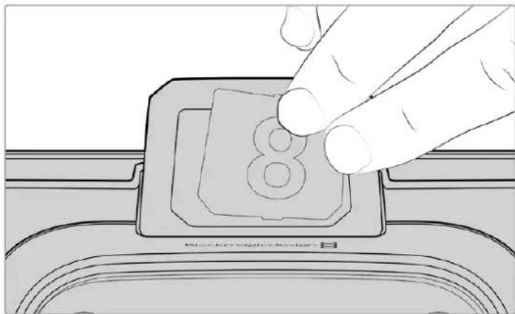
Tally light numbers can be easily changed
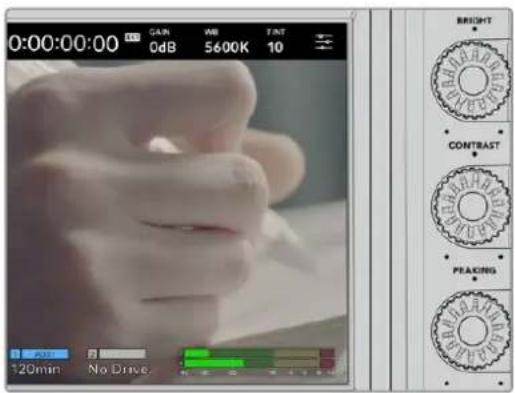
Bright, Contrast and Peaking
Use these three dials to adjust the brightness, contrast and focus peaking level on the LCD touchscreen.
You can use a traditional focus peaking style, plus the option to use coloured lines with red, green, blue, black or white lines.
Touchscreen Display
Monitor the image using the built in touchscreen. Tap and swipe to zoom and adjust settings.

Back/PGM Button
When connected to an ATEM switcher, pressing and holding the 'program' button on Blackmagic Studio Camera 4K Pro displays the return feed on the LCD. Releasing the button returns you to your live camera image. Double press the PGM button to lock on the program return feed. Press again to return to your live camera image.
On Blackmagic Studio Camera 4K Plus, this button is labeled 'back'. Press the back button to close the menu settings and return the LCD to the live image.

Function Buttons
These are assignable buttons you can set for easy access to your most commonly used functions. The default functions for these buttons are:
F1-Focus zoom.

F2 - Focus. Will trigger auto focus on compatible lenses.
F3 - Iris. Will trigger auto iris on compatible lenses.
For more information on assigning the function buttons, refer to the 'setup settings' chapter in the 'menu settings' section.
ON/OFF switch
Switches the camera on and off.
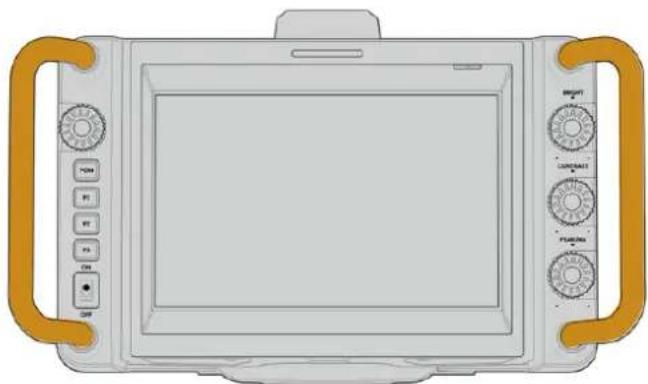
Handles
Built in handles on each side of your camera let you hold the camera when carrying and setting up. They also help protect the screen when setting up and packing down.
Touchscreen Controls
Your Blackmagic Studio Camera's LCD touchscreen features a tap and swipe gesture based interface. By tapping and swiping on the status display and icons, you can quickly open the head up display and access the camera's settings while shooting.
Your studio camera's LCD touchscreen lets you monitor the image and change settings
Changing Settings using the Head up Display
The head up display is a quick settings menu you can open and change by tapping on a setting. Simply tap on an item to open the head up display, then make changes using the touchscreen or rotating the settings dial. After making your selection, press the dial to quickly close the selection menu.
Tap a setting on the touchscreen and make a change by turning the settings dial. Press again to close.
Head up Display Settings
This section of the manual describes the settings you can change using the head up display and settings dial.
LCD Monitor Options
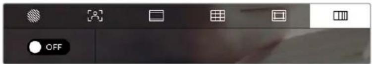
Tap the 'monitor' icon at the top left of the touchscreen to access the LCD monitor settings. These settings let you toggle and adjust the appearance of your studio camera's monitoring features, including zebra, focus assist, frame guides, grids, safe area guides and false color. When accessing LCD monitor options, the controls for these features appear in a tabbed menu along the bottom edge of the LCD touchscreen.
Tap the icon at the top left of your camera's LCD touchscreen to access LCD monitor options
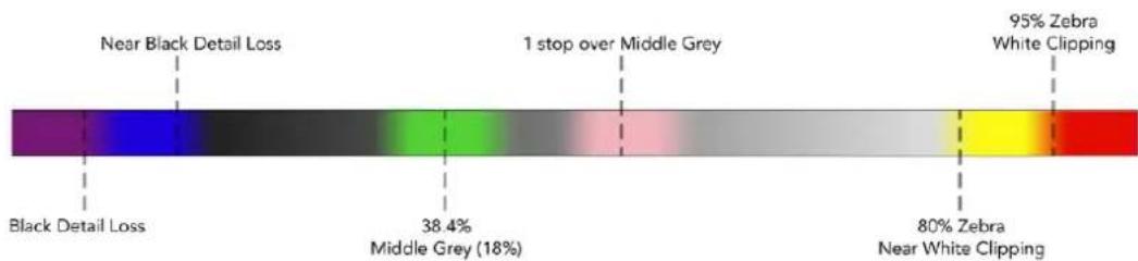
Zebra
The 'zebra' setting toggles the appearance of the zebra on the LCD touchscreen, as well as setting the zebra level.
Zebra displays diagonal lines over areas of your image that exceed a set exposure level. For example, setting zebra to 100% shows which areas are completely overexposed. This is useful for achieving optimum exposure in fixed lighting conditions.
Tap the 'zebra' icon while accessing LCD monitor options' to access the zebra settings
To toggle the zebra for the LCD touchscreen, tap the switch icon in the bottom left of the screen while in the 'zebra' tab.
Set the exposure level at which the zebra appears by dragging the slider left and right, or tapping the arrow buttons next to the zebra level percentage. Zebra level is adjustable in five percent steps between 75 and 100 percent exposure.
For information on enabling zebra on your camera's HDMI or SDI output, see the 'monitor settings' section in this manual.
TIP If you're shooting in variable light such as outdoors on a partly overcast day, setting your zebra level lower than 100 can warn you of potential overexposure.
Focus Assist
The 'focus assist' setting toggles the appearance of focus assist on the LCD touchscreen, as well as setting the level of focus assistance.
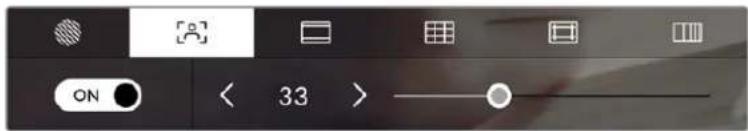
Tap the 'focus assist' icon while accessing 'LCD monitor options' to access your camera's focus assist settings
To toggle focus assistance for the LCD touchscreen, tap the switch icon in the bottom left of the screen while in the 'focus assist' tab. To set the level of focus assistance move the slider left and right along the bottom of the touchscreen.
The optimum level of focus assistance varies shot by shot. When focusing on actors, for example, higher level of focus assistance can help resolve edge detail in faces. A shot of foliage or brickwork, on the other hand, may show distracting amounts of focus information at higher settings.
For information on enabling focus assist on your camera's HDMI output on both camera models and the SDI output on the Studio Camera 4K Pro, see the 'monitor settings' section in this manual.
TIP Your Blackmagic Studio Camera has two focus assist modes. You can switch between 'peaking' and 'colored lines' focus assistance in the 'monitor' settings menu. For more information, see the 'monitor settings' section in this manual.
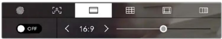
Frame Guides
The 'frame guide' setting toggles the appearance of frame guides on the LCD touchscreen. Frame guides include aspect ratios for various cinema, television and online standards.
Tap the 'frame guides' icon while accessing LCD monitor options to access your frame guide settings
To toggle the appearance of frame guides on the LCD touchscreen, tap the switch icon in the bottom left of the screen.
Choose the frame guide you want to use by dragging the slider left and right, or tapping the arrow buttons on either side of the currently selected aspect ratio. You can also enter a custom frame guide ratio by tapping on the ratio between the arrow buttons.
The available guides are:
2.35:1, 2.39:1 and 2.40:1
Displays the broad widescreen aspect ratio compatible with anamorphic or flat widescreen cinema presentation. The three widescreen settings differ slightly based on the changing cinema standards over time. 2.39:1 is one of the most prominent standards in use today.

The LCD touchscreen with 2.40:1 frame guides enabled
2:1
Displays a ratio slightly wider than 16:9 but not as wide as 2.35:1.
1.85:1
Displays another common flat widenscreen cinema aspect ratio. This ratio is slightly wider than HDTV 1.78:1 but not as wide as 2.39:1.
16:9
Displays a 1.78:1 aspect ratio compatible with 16:9 HD television and computer screens. This ratio is most commonly used for HD broadcasting and online videos. The same aspect ratio has also been adopted for Ultra HD broadcasting.
14:9
Displays a 14:9 aspect ratio used by some television broadcasters as a compromise between 16:9 and 4:3 television sets. Ideally, both 16:9 and 4:3 footage remains legible when center cropped to fit 14:9. You can use this as a compositional guide if you know your project may be broadcast by a television station that uses 14:9 cropping.
4:3
Displays the 4:3 aspect ratio compatible with SD television screens, or to help with framing when using 2x anamorphic adapters.
1:1
Displays a 1:1 ratio slightly narrower than 4:3. This square ratio is growing in popularity on social media.
4:5
Displays a 4:5 aspect ratio. This vertical aspect ratio is ideal for portraits and viewing on smartphones.
Custom Frame Guide Ratio
To create your own frame guide ratio for a unique appearance, tap on the ratio displayed between the arrow buttons. On the 'custom frameguide' screen tap the backspace button to delete the current ratio, then use the numeric keypad to specify a new ratio. Tap 'update' to apply your custom frame guide ratio and return to shooting.

Use the numeric keypad on the 'custom frame guide' screen to enter a new guide ratio
TIP You can change the opacity of frame guide overlays and enable or disable them on your camera's HDMI or SDI output. For more information see the 'monitor settings' section of this manual.
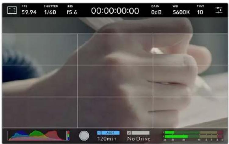
Grids
The 'grids' setting toggles the appearance of a rule of thirds grid, horizon meter, crosshair or center dot on the LCD touchscreen.

Tap the 'grids' icon while accessing 'LCD monitor options' to access the grid settings
Grids and crosshair are overlays that can help with image composition. When 'grids' are enabled, the LCD shows a rule of thirds grid, horizon, crosshair or dot.
To toggle the appearance of grids on your camera's touchscreen, tap the switch icon in the bottom left of the screen while in the 'frame guides' tab.
To set which overlay you want to display on the LCD, tap the 'thirds', 'horizon', 'crosshair' or 'dot' options. You can select one of 'horizon', 'crosshair' or 'dot' at a time in conjunction with 'thirds'. This lets you use a combination of 'thirds' and 'horizon', 'thirds' and 'crosshair', or 'thirds' and 'dot'.
The rule of thirds grid automatically scales to any on screen frame guides
Thirds
The 'thirds' setting displays a grid with two vertical and horizontal lines placed in each third of the image. Thirds are an extremely powerful tool to help compose your shots. For example, the human eye typically looks for action near the points where the lines intersect, so it's helpful to frame key points of interest in these zones. An actor's eyeline is commonly framed along the top third of the screen, so you can use the top horizontal third to guide your framing. Thirds are also useful to maintain framing consistency between shots.
Horizon
The 'horizon' meter indicates when your camera is rolled left or right and tilted up or down. Use this meter to ensure your image always has a level horizon.
The distance the lines move away from the central crosshair is proportional to the amount of roll or tilt. After you calibrate the camera's motion sensor, the moving lines turn blue when aligned to their axis.
Note that if the camera is tilted straight down for an overhead shot or straight up, the horizon meter takes this into account. If you roll the camera to shoot in portrait orientation, the horizon meter rotates its axes 90 degrees.
This table shows examples of the horizon meter indicating tilt and roll of the camera.
Horizon meter Description

Straight and level

Tilted down and level

Straight and rolled left

Tilted up and rolled right
For normal use, calibrate the horizon meter for straight and level operation. If you want to use the horizon meter to help maintain a consistent 'dutch angle' or a consistent tilt for a low or high shot, you can calibrate the horizon meter at an incline. For information on how to calibrate the horizon meter, see the 'motion sensor calibration' section.
Crosshair
'Crosshair' setting places a crosshair in the center of the frame. Like thirds, the crosshair is a very useful compositional tool, making it easy to frame the subject of a shot in the very center of a frame. This is sometimes used when filming scenes that will be assembled using fast cuts. Keeping viewers' eyes focused on the center of a frame can make rapid editing easier to follow.
Dot
The 'dot' setting places a dot in the center of the frame. This works in exactly the same way as the 'crosshair' setting, albeit with a smaller overlay that you may find less intrusive.
NOTE For information on enabling grids on your HDMI or SDI output, see the 'monitor settings' section in this manual.
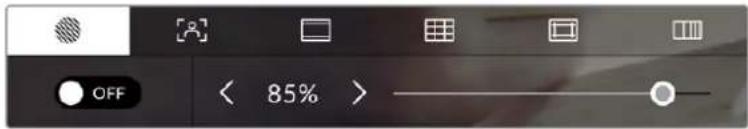
Safe Area Guides
The 'safe area guides' setting toggles the safe area guides on or off the LCD touchscreen, as well as setting the size of safe area guides.
Safe areas can be used in broadcast production so the most important parts of a shot can be seen by viewers. By keeping the most important parts of your shot inside a central 'safe area,' you can avoid cropping on some televisions, as well as leaving space for a broadcaster to add bugs, news tickers and other overlays along the edges of the screen. Many broadcasters require footage to be submitted with important content, such as titles and graphics, contained inside the 90% safe area.
Safe area guides can also be used to assist with framing your shot where you know that the shot will be stabilised in post production, which can crop the edges of the image. They can also be used to indicate a specific crop. For example by setting it to 50% when recording at Ultra HD 3840x2160 you can see what a 1920x1080 crop of the frame would look like. The safe area guides also scale to your frame guides, so they will adjust to indicate the chosen percentage of your target frame.
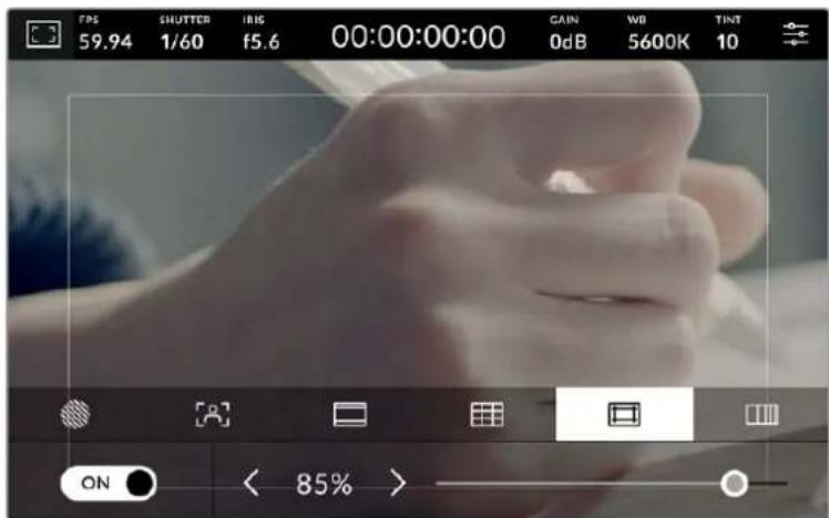
The 'safe area' indicator set to 85%
To toggle safe area guides for the LCD touchscreen, tap the switch icon in the bottom left of the screen while in the 'safe area guides' tab. To set the level of safe area guides for your camera's LCD touchscreen, tap the left or right arrows on either side of the current numerical value at the bottom of the touchscreen. Alternatively, you can drag the slider left or right.
For information on enabling safe area guides on your camera's HDMI or SDI output, see the 'monitor settings' section in this manual.
False Color
The 'false color' setting toggles the appearance of false color exposure assistance on the LCD touchscreen.
False color overlays different colors onto your image that represent exposure values for different elements in your image. For example, pink represents optimum exposure for lighter skin tones, while green is a good match to darker skin tones. By monitoring the pink or green false color when recording people, you can maintain consistent exposure for their skin tones.
Similarly, when elements in your image change from yellow to red, that means they are now over exposed.
False Color Chart
To toggle false color for the LCD touchscreen, tap the switch icon in the bottom left of the screen while in the 'false color' tab.
The 'false color' exposure assistance tab
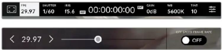
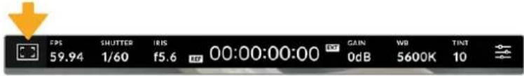
Frames Per Second
The 'FPS' indicator displays your currently selected frames per second.
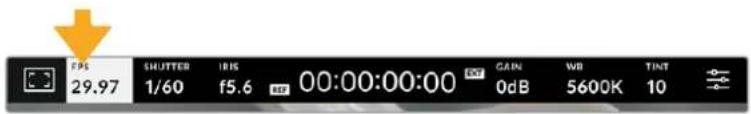
Tap the frames per second indicator to access frame rate settings
Tapping the 'FPS' indicator lets you change your camera's sensor and project frame rates via a menu at the bottom of the LCD touchscreen.
Project Frame Rate
The project frame rate is the camera's recording format frame rate and provides a selection of common frame rates used in the film and television industry. This frame rate should normally be set to match your broadcast delivery format.
8 project frame rates are available including 23.98, 24, 25, 29.97, 30, 50, 59.94 and 60 frames per second.
To adjust your camera's project frame rate while in the 'FPS' menu, tap the left or right arrows next to the current frame rate at the bottom left of your touchscreen. Alternatively, you can drag the slider left or right.

Tap the arrows on either side of the project frame rate or move the slider to make adjustments
Sensor Frame Rate
The sensor frame rate sets how many actual frames from the sensor are recorded every second. This frame rate will affect how fast or slow your recorded video will play back at your set project frame rate in DaVinci Resolve.
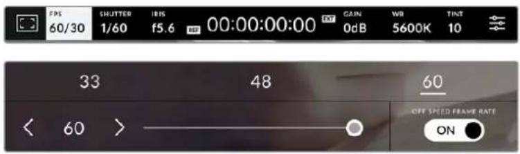
With 'off speed frame rate' enabled, tap a preset or the arrows on either side of the sensor frame rate or move the slider to make adjustments
By default, the project and sensor frame rates are matched for a natural playback speed. However, by tapping the 'off speed frame rate' switch icon in the bottom right hand side of your camera's 'FPS' menu, you can independently set the sensor frame rate.
To change the sensor frame rate, tap the arrows next to the sensor frame rate indicator in the lower left of your touchscreen. You can also drag the slider left or right to increase or decrease the frame rate. Above the slider, you can tap on a common off speed frame rate. These are based on your current project frame rate.
You can create dynamic and interesting speed effects in DaVinci Resolve by varying the sensor frame rate for your recorded video. Setting the sensor frame rate higher than your project frame rate will create slow motion during playback.
Shutter
The 'shutter' indicator displays your shutter speed or shutter angle. By tapping this indicator, you can manually change your camera's shutter values or configure shutter priority auto exposure modes. The shutter measurement setting can be used to select whether to display shutter information as 'shutter speed' or 'shutter angle'. See the 'setup settings' section in this manual for more information.
Tap the shutter indicator to access shutter settings
Shutter speed defines the level of motion blur in your video, and can be used to compensate for varying light conditions. The shutter speed setting for natural motion blur, and the settings available, depend on the frame rate you are using. For example, when shooting at 30p, a 1/60 of a second shutter speed is the equivalent of a 180 degree shutter angle, a very common setting for film projects. However if you are shooting at 25p, you will need to set the shutter to 1/50 for the same look. As lighting conditions change, or the amount of movement in your scene increases, you may decide to adjust accordingly.
For natural motion blur you can calculate the shutter speed by doubling your frame rate. So at 30p, set your shutter speed to 1/60 of a second for natural motion blur.
If you need more light on the sensor, you can set the shutter at the slowest setting corresponding with your frame rate. For example, 1/25 for 25p, or 1/30 for 30p. At the slowest shutter speed, your motion blur will appear slightly exaggerated.
If you want to reduce the motion blur so action appears sharper and more defined, set the shutter to a faster speed, such as 1/120 of a second for 30p, or 1/100 of a second for 25p. If you are familiar with shutter angles, this equates to a shutter angle of 90 degrees.
NOTE When shooting under lights, your shutter can affect the visibility of flicker. Your Blackmagic Studio Camera will automatically calculate a flicker free shutter value for your current frame rate. Three suggested flicker free shutter options will appear at the bottom of the touchscreen display when adjusting your shutter. These shutter values are affected by mains power frequency in your region. You can set your local power frequency to 50Hz or 60Hz in the camera's setup menu. See the 'setup settings' section in this manual for more information.
Tapping the 'shutter' indicator brings up the suggested shutter values along the bottom of the touchscreen. If you have auto exposure set to 'off,' this screen will show you your currently
selected shutter value, as well as the available flicker free shutter values, based on the mains power frequency you have selected in your camera's setup menu. The characteristics of individual light sources may still cause flicker even when using flicker free values. We recommend always performing a test shoot when not using continuous lights. For more information, see the 'setup settings' section in this manual.
To select one of the flicker free shutter values, simply tap on one of the displayed shutter values. Using the arrows on either side of the current shutter value indicator, will cycle through some of the most commonly used values.

Your camera will suggest flicker free shutter values based on the mains power frequency you choose in the 'setup' menu
If you would like to choose a specific shutter value, you can do so by double tapping the current shutter indicator at the bottom left of your screen. This will bring up a keypad that allows you to type in any shutter value you wish.
If you type in a shutter value that is less than your current frame rate, for example 1/25th when shooting at 29.97 frames per second, the nearest achievable shutter value will be used. The nearest shutter speed in this example would be 1/30th.
Use the manual shutter keypad to enter your shutter timing of choice when shooting outdoors or under flicker free lights
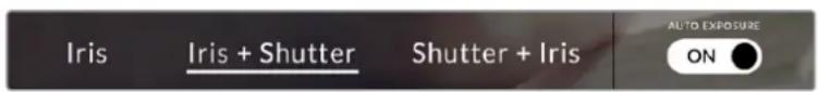
Tapping the 'auto exposure' switch icon at the far right of the shutter menu opens the shutter auto exposure menu.
This gives you the following auto exposure options.
Shutter
This setting automatically adjusts shutter value to maintain a constant exposure while keeping iris aperture consistent. If you want to maintain a fixed depth of field, this is the setting to choose. It's worth mentioning that the subtle automatic adjustments of the shutter may have an effect on motion blur. It's also worth keeping an eye out for any flicker that may be introduced from various light fixtures on indoor shoots. The auto iris feature is not available when the 'shutter' auto exposure mode is selected.
Shutter + Iris
Maintains the correct exposure levels by adjusting the shutter, then the aperture. If the maximum or minimum available shutter value is reached and exposure still cannot be maintained, your camera adjusts the aperture to keep exposure consistent.
Iris + Shutter
Maintains the correct exposure levels by adjusting the aperture, then the shutter value. If the maximum or minimum available aperture is reached and exposure still cannot be maintained, your camera adjusts the shutter value to keep exposure consistent.
While in the shutter menu, tap 'auto exposure' to access shutter based auto exposure modes
TIP When an auto exposure mode that effects the shutter or iris is enabled, a small 'A' appears next to the shutter or iris indicator at the top of the LCD touchscreen.
Iris
The Iris' indicator displays your current lens aperture. By tapping this indicator, you can change the aperture of compatible lenses and configure iris based auto exposure modes.
Tap the iris indicator to access iris settings
Tapping the 'iris' indicator once brings up the iris menu along the bottom of the touchscreen. You'll see your current lens aperture at the far left of this menu. You can change the aperture by tapping the left and right arrows on either side of the current aperture, or moving the slider left or right.

While in the 'iris' menu, tap the arrows on either side of the iris indicator or use the slider to adjust iris settings
Tapping the 'auto exposure' switch icon at the far right of the iris menu opens the iris auto exposure menu.
This gives you the following auto exposure options.
Iris
This setting automatically adjusts the aperture to maintain a constant exposure while keeping shutter speed consistent. This will keep motion blur unaffected, but may affect your depth of field.
Iris + Shutter
Maintains the correct exposure levels by adjusting the aperture, then the shutter value. If the maximum or minimum available aperture is reached and exposure still cannot be maintained, your camera adjusts the shutter value to keep exposure consistent.
Shutter + Iris
Maintains the correct exposure levels by adjusting the shutter, then the aperture. If the maximum or minimum available shutter value is reached and exposure still cannot be maintained, your camera adjusts the aperture to keep exposure consistent.
While in the iris menu, tap 'auto exposure' to access iris based auto exposure modes
TIP When an auto exposure mode that effects the iris or shutter is enabled, a small 'A' appears next to the iris or shutter indicator at the top of the LCD touchscreen.
Duration Display
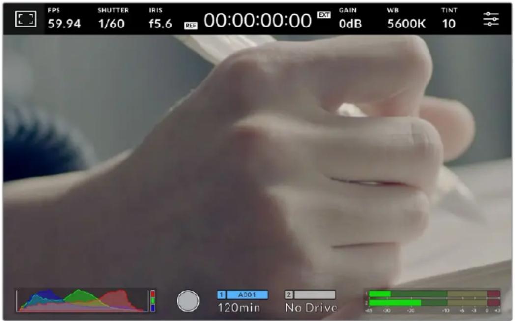
At the top of your camera's LCD touchscreen, you'll see your camera's duration display.
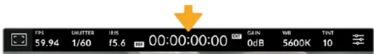
Your camera's duration display will turn red while recording.
The duration display provides a timecode counter for checking the duration of your clips and monitoring timecode during recording. The counter displays a time sequence showing Hours:Minutes:Seconds:Frames and will change accordingly as you record or play back clips. During recording the timecode is red.
The displayed duration starts from 00:00:00:00. The clip duration of the current or last recorded clip is displayed on the touchscreen. Time of day timecode is embedded into clips for easier post production.
To see the timecode, simply tap the duration display. Tap the duration display again to return to clip duration.
Additional status indicators may appear around the duration display:
| TC | Appears to the right of the duration display when showing timecode. |
| EXT | Appears to the right of the duration display if an external timecode signal is connected and valid. This can be fed from an ATEM Mini via HDMI, an ATEM switcher via SDI Program return or from an analog mini jack or XLR timecode source. |
| INT | Appears to the right of the duration display if the camera is running off an internal timecode after being ‘jam syncsed’ and disconnected. |
| REF | Appears when a valid reference source is connected and locked, based on the reference input settings. |
When connected to ATEM switchers, your studio camera will display a small tally status overlay on the LCD touchscreen below the timecode. This means you can disable the tally light on the camera, but still see if your studio camera has been switched to the preview output or is live to air.
ATEM switchers automatically synchronize the timecode on your studio camera to match the switcher's timecode when connected. This makes it easier to perform accurate multi camera edits in DaVinci Resolve.
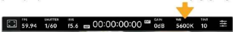
Gain
The 'Gain' indicator displays your studio camera's current gain setting, or light sensitivity. Tapping this indicator lets you adjust your gain to suit varying lighting conditions.
The optimum setting for your studio camera is 0dB. Your camera has a dual native ISO sensor, meaning that 10dB and 18dB are excellent for low light situations, producing clean images with very little noise.
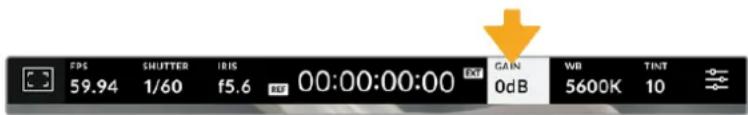
Tap the gain indicator to access gain settings
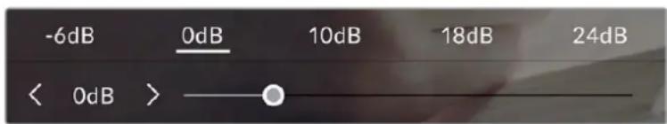
The slider and arrows below the presets let you adjust the gain in 1/3 stop increments
Depending on your situation, you may choose a lower or higher gain setting. For example, 32 or 36dB can be used in ultra low light but may cause noise.
Dual Native Gain
The sensor in your Blackmagic Studio Camera is optimized for shooting in low light conditions as well as bright daylight.
Adjust the gain for the varying lighting conditions and the dual native gain feature will operate in the background to make sure your footage is clean and has minimal noise at low and high gain settings.
When the gain setting is between -12dB and 8dB the native gain of 0dB is used as a reference point. The gain range between 10dB and 36dB uses the native gain of 18dB as a reference. If you are shooting in conditions where you have a choice between 8dB or 10dB we suggest closing down one stop on your lens' iris so that you can select 10dB as it will engage the higher native gain and provide much cleaner results.
The dynamic range chart in this section shows the relationship between the gain selection and dynamic range allocation.
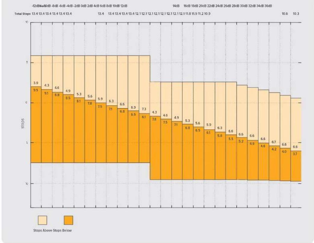
Blackmagic Studio Cameras Dynamic Range Chart
White Balance
The 'WB' and 'TINT' indicators display your camera's current white balance and tint. Tapping these indicators lets you adjust your camera's white balance and tint to suit varying lighting conditions.
Tap the white balance and tint indicators to access white balance and tint settings
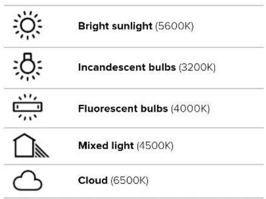
Every light source emits a color. For example, a candle flame emits a warm color, and an overcast sky emits a cool color. White balance settings are used to color balance your image so white stays white by adjusting the mix of orange and blue in your image. For example, when shooting under tungsten lamps which emit a warm, orange light, selecting 3200K adds some blue to the image. This balances the color so white is accurately recorded.
Your Blackmagic Studio Camera comes with white balance presets for a variety of color temperature conditions. These are:
To customize the presets, tap or tap and hold the arrow icons to the left and right of the temperature indicator. Each tap moves the color temperature up or down 50K. Holding the arrow icons down will increase the speed. Alternatively, you can drag the temperature slider left or right.
To further dial in your image, you can adjust the 'tint.' This adjusts the mix of green and magenta in your image. For example, adding some magenta can compensate for the green cast of many fluorescent lights. Many of your camera's white balance presets include some tint.
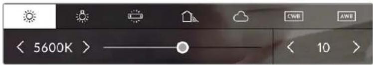
Tapping the white balance and tint indicator gives you access to five presets, as well as a white balance indicator and slider on the left, and a tint indicator on the right. Adjust these to set a custom white balance for your lighting conditions.
In a similar fashion to white balance, tap the tint indicator's left and right arrows to make a change. The available range is -50 to +50 in one unit steps. Holding down on the arrows speeds up adjustment.
NOTE Customizing the white balance or tint will change your preset to 'CWB,' or custom white balance. Custom white balances are persistent; your CWB settings will stay configured between power cycles, and when switching to a preset and back to CWB. This makes it easy to compare a custom white balance to the last preset used.
Auto White Balance
Your Blackmagic Studio Camera can set white balance automatically. Tapping 'AWB' will open the white balance screen.
When setting white balance automatically, a square will be overlaid on the center of your image. Fill this square with a neutral surface such as a white or gray card and tap 'update WB'. The camera will automatically adjust its white balance and tint values so the average of the white or grey inside the white balance square is as neutral as possible. Once updated, this will be set as your camera's custom white balance. Holding the WB button on the top of your camera for three seconds also selects automatic white balance and activates the 'update WB' function.
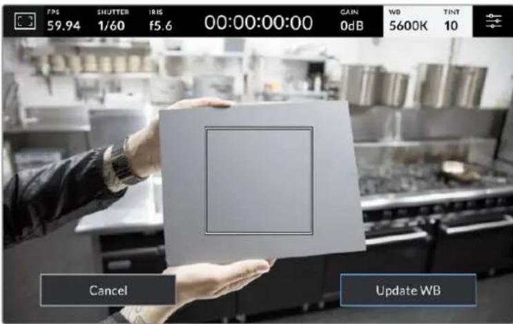
Tapping the 'AWB' icon in the white balance menu will bring up the auto white balance screen. Use this with a white or neutral grey surface to automatically set a neutral white balance.
LUT indicator
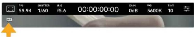
When you are using a LUT as a preview tool on set, a LUT icon will be displayed in the top left corner of the screen to indicate that the LUT is currently active.
Histogram
At the bottom left of your camera's touchscreen you can see the histogram.
The histogram displays the strength of the red, green and blue color channels corresponding to the tonal ranges in your image. For example, the shadows will feature towards the left, the mid tones in the middle and the highlights towards the right. When you close or open the lens aperture, you'll notice the information in the histogram moves to the left or right accordingly.
The histogram is a good indicator for exposure, but is also used to check 'clipping' for each channel. If the shadows or highlights in the graph meet the edge harshly rather than falling off gradually, you will be losing highlight or shadow detail. When clipping occurs in the highlights, the 'traffic light' indicator on the right of the histogram will indicate which color channels are affected.

The histogram gives you an indication of the tonal range between shadows and highlights in your clip. It is also a helpful tool for checking the balance of your exposure and to prevent your highlights from clipping.
NOTE If you don't see a histogram in the bottom left of your touchscreen, your LCD monitor settings may be set to display 'codec and resolution.' See the 'monitor settings' section in this manual for more information.
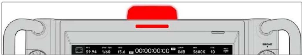
Record button
Next to the histogram, at the bottom of your studio camera's touchscreen, is a round grey button. This is the 'record' button. Tap it once to begin recording, and tap it again to stop. While recording, the button, storage indicator and the timecode at the top of your Studio Camera's touchscreen turn red.

When recording, the record button displays red
When your camera is connected to an ATEM Mini, recording can be triggered on all cameras simultaneously using the 'record stream' palette in ATEM Software Control.
Dropped Frame Indicator
The 'record' button is overlaid with a flashing '!' indicator if your camera begins dropping frames while recording. The time remaining indicator for the affected flash disk also turns red. For example, if your USB-C flash disk is dropping frames, the '!' indicator appears over the 'record' button, and the time remaining indicator on the flash disk turns red. This lets you know if a particular flash disk is too slow for your currently selected codec and resolution. The 'dropped frame indicator' also appears if you have dropped a frame on the previously recorded clip. This indicator continues until another clip is recorded, or the camera is power cycled.

The dropped frame indicator appears when a flash drive is dropping frames
NOTE You can set your Blackmagic Studio Camera to stop recording if dropped frames are detected to avoid recording unusable footage. See the 'record settings' section in this manual for more information.
Recording Time Remaining
When a USB-C flash disk is attached to your camera, the storage indicator at the bottom of the touchscreen show how much recording time is left on the drive. The time is shown in minutes and varies according to your selected frame rate and codec. The indicator automatically recalculates if either of these settings are changed. When there is approximately five minutes remaining on your drive, the indicator text turns red. The indicator will also blink if a second drive is not connected and your recording drive has less than 2 minutes of record time remaining. 'Full' will be displayed when a drive reaches maximum capacity.
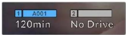
The storage indicator shows the name of your or USB-C flash disk and the record time remaining in minutes
The drive name is also presented in a small bar above the time remaining. The bar turns blue to indicate the camera is set to record to this USB-C flash disk. To record to a different drive, press and hold the name of the drive you wish to record to. While recording, the bar is red.
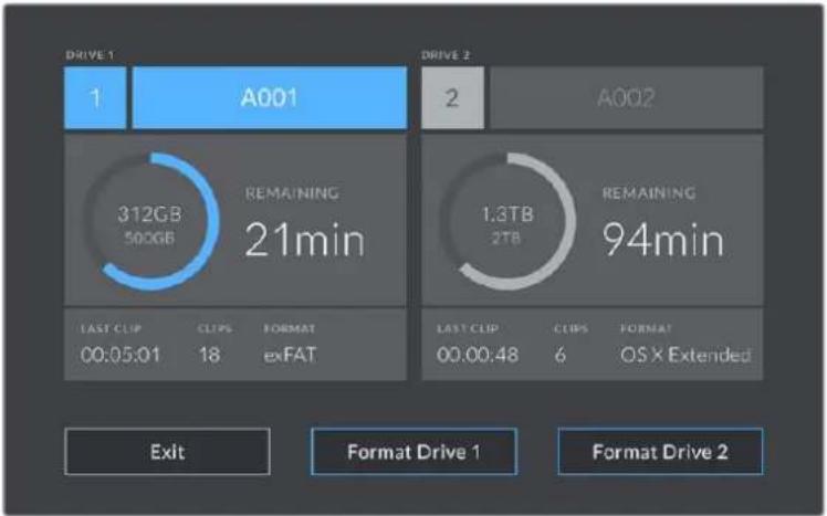
Tap the storage indicator on the LCD touchscreen to access the storage manager
This menu displays the amount of free space on each USB-C flash disk used by your camera, as well as the name of the drive, length of the last clip, total number of clips, and the file format for each drive.
You can format your media from this menu. For more information, see the 'preparing media for recording' section of this manual.
TIP Tapping the drive name in the storage menu sets it as the active drive. Your Blackmagic Studio Camera fills this drive first.
Triggering Record using ATEM Mini
When recording ISO files from an ATEM Mini Pro or Extreme model switcher, you can also trigger record on all studio cameras connected via HDMI.
For example, the 'record stream' palette in ATEM Software Control has a checkbox labeled 'record in all cameras'. When this checkbox is enabled and you click or press record, all connected studio cameras will start recording as well. This means you only have to click or press one button to start recording on all cameras simultaneously.
Refer to the ATEM Mini manual for more information.
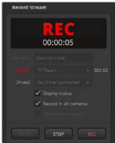
When recording on ATEM Mini Pro model switchers, all studio cameras can be set to record when you click the record button in ATEM Software Control's record stream palette
Audio Meter
The peak audio meters display audio levels for channels 1 and 2 when using the internal microphone, or via external audio when connected. The display is calibrated to dBFS units and features peak hold indicators which stay visible for a short time so you can clearly see the maximum levels reached.
You can select from PPM or VU measurement scales.
To achieve optimum audio quality, ensure your audio levels do not reach 0 dBFS. This is the maximum level that your camera can record, meaning that any audio that exceeds this level will be clipped, resulting in distortion.
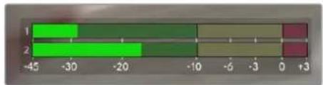
The colored bars on the audio meter represent peak audio levels. Ideally your peak audio levels should fall in the upper end of the green zone. If your peaks enter into the yellow or red zones your audio is in danger of clipping.
Tap the audio meter to open volume controls for audio input channels 1 and 2, as well as headset volume.
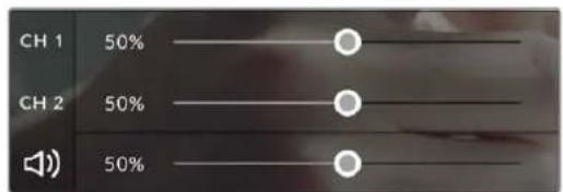
Tap the audio meters on the LCD touchscreen to access audio channel and headset volume controls. For more information, see the 'audio settings' section in this manual.
Double Tap to Zoom
You can magnify any part of your Blackmagic Studio Camera's preview image by double tapping the LCD touchscreen. The area you tap will be magnified, and you can move around the image by dragging your finger around the LCD touchscreen. This is very helpful when checking focus. To return to standard magnification, simply double tap your camera's touchscreen again.
The digital zoom feature can be assigned to a function button and is referred to as 'focus zoom'.
Pinch to Zoom
You can adjust the zoom level on the LCD touchscreen with a pinch to zoom multitouch gesture. This does not affect the HDMI output.
To start zooming at × 2 , double tap on the touchscreen. Pinch out to increase magnification and pinch in to decrease. Touch and drag to move the magnified area. To return to the standard magnification, double tap on the touchscreen again.
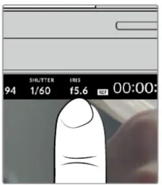
Touch to Focus
You can focus your lens in any region of the image by tapping and holding on the LCD screen in the area that you want to focus. If you want to focus on a magnified area of the screen, double tap and then tap and hold to auto focus. Double tap to return to normal viewing.
Full Screen Mode
It can be useful when framing or focusing a shot to temporarily hide the lower third overlays on the touchscreen, for example the histogram, storage indicators and audio meters. The status display at the top of the screen features above and separate from the image, so is always visible. To hide lower third overlays, swipe up or down on the LCD touchscreen. The record indicator, frame guides, grids, focus assist and zebra remain visible.

Swipe up or down to hide lower third overlays on the LCD touchscreen
Menu Settings
While the head up display lets you quickly change some important settings, all of your camera's settings are accessed using the main menu settings.
To open the settings menu and make a change, simply tap on the menu button in the top right hand corner. This opens the settings menu on the LCD and you can now tap and swipe items to make changes.
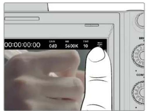
Tap the menu settings icon and use the touchscreen to change settings
Settings are divided by functions into 'record,' 'monitor,' 'audio,' 'setup,' 'presets,' and 'LUTs' tabs. Each tab has multiple pages, which you can cycle through by tapping the arrows at the edge of your camera's touchscreen, or swiping left or right.
Tap the 'record', 'monitor', 'audio', 'setup', 'presets' and 'LUTs' headings to move through your studio camera's menu tabs
Record Settings
The 'record' tab lets you set your video format, codec, and resolution, as well as other settings that are important for your recorded video, such as dynamic range and detail sharpening. You can also set the codec and quality for when recording to external media connected to your camera's USB port, for example an external flash drive.
Record Settings Page 1
The first page of the 'record' settings tab contains the following settings.
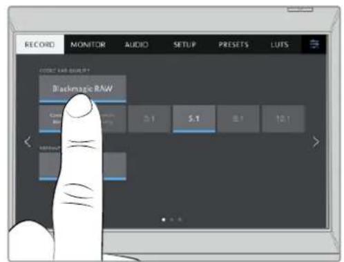
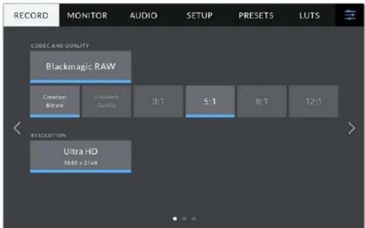
Codec and Quality
The 'codec and quality' menu lets you set the quality for Blackmagic RAW when recording externally. You can choose from a selection of constant bitrate settings, or constant quality. For example 3:1, 5:1, 8:1, 12:1, or Q0, Q1, Q3 and Q5 respectively. These provide options so you can set the amount of compression used. More information on Blackmagic RAW is provided later in this section.


Blackmagic RAW quality options
Tip You can increase the recording durations on external storage media connected to your Blackmagic Studio Camera if you choose CODECs that use higher compression. Refer to the 'record duration' tables in the 'recording' section for more information.
Resolution
This setting displays the resolution being recorded if you are recording to an external flash disk via USB-C.

Displays the resolution being recorded via USB-C
Blackmagic RAW
Blackmagic Studio Cameras support the Blackmagic RAW file format. This format offers superior image quality, wide dynamic range and a broad selection of compression ratios. Blackmagic RAW features all the user benefits of RAW recording, but the files are very fast because most of the processing is performed in the camera where it can be hardware accelerated by the camera itself.
Blackmagic RAW also includes powerful metadata support so the software reading the files knows your camera settings. If you like shooting in video gamma because you need to turn around edits quickly and you don't have time for color correction, then this metadata feature means you can select video gamma, shoot in video gamma, and the file will display with video gamma applied when you open it in software. However underneath, the file is actually film gamma and the metadata in the file is what's telling the software to apply the video gamma.
So what all this means is if you want to color grade your images at some point, then you have all that film dynamic range preserved in the file. You don't have your images hard clipped in the whites or the blacks, so you retain detail and you can color grade to make all your images look cinematic. However, if you don't have time for color grading, that's fine because your images will have the video gamma applied and look like normal video camera images. You are not locked in on the shoot and you can change your mind later during post production.
Blackmagic RAW files are fast with the codec optimized for your computer's CPU and GPU. This means it has fast smooth playback and eliminates need for hardware decoder boards, which is important for laptop use. Software that reads Blackmagic RAW also gets the advantage of processing via Apple Metal, Nvidia CUDA and OpenCL. Blackmagic RAW plays back at normal speed like a video file on most computers, without needing to cache it first or lower the resolution.
It's also worth mentioning that lens information is recorded in the metadata on a frame by frame basis. For example, when using compatible lenses, any zoom or focus changes performed over the length of a clip will be saved, frame by frame, to the metadata in the Blackmagic RAW file.
Recording to Blackmagic RAW
Blackmagic RAW works in 2 different ways. You have a choice to use either the constant bitrate codec, or the constant quality codec.
Constant bitrate codec works in a similar way to most codecs. It tries to keep the data rate at a consistent level and won't let the data rate go too high. This means even if you are shooting a complex image that might need a bit more data to store the image, a constant bitrate codec will compress the image harder to make sure the images fit within the space allocated.
This can be fine for video CODECs, however when shooting Blackmagic RAW you really want to ensure the quality is predictable. What would happen if the images you were shooting needed more data, but the codec just compresses harder to make a specified data rate? It's possible you could lose quality, but not be sure it's happening until you return from a shoot.
To solve this problem, Blackmagic RAW also has an alternative codec choice called constant quality. This codec is technically called a variable bitrate codec, but what it's really doing is allowing the size of the file to grow if your images need extra data. There is no upper limit on the file size if you need to encode an image but maintain quality.
So Blackmagic RAW set to the constant quality setting will let the file grow as big as it needs to be to encode your images. It also means the files could be larger or smaller depending on what you are shooting.
It is also worth noting that the quality settings for Blackmagic RAW are not obscure names, but are more meaningful as they are derived from what's happening technically. So for example when you have selected the constant bitrate codec, you will see quality settings of 3:1, 5:1, 8:1 and 12:1. These are the ratios of the uncompressed RAW file size vs the file sizes you should expect when shooting in Blackmagic RAW. 3:1 is better quality as the file is larger, while 12:1 is the smallest file size with the lowest quality. Many users of Blackmagic RAW find that 12:1 has been perfectly ok and they have not seen any quality limitations. However it's best to experiment and try various settings for yourself.
When using Blackmagic RAW in constant quality you will see the settings are Q0, Q1, Q3 and Q5 on your studio camera. These are the compression parameters passed to the codec and they are setting how much compression is applied in a more technical way. This setting is different because the codec operates differently between constant bitrate vs constant quality. In this constant quality setting, you really cannot tell what the file size ratio will become as it varies a lot based on what you are shooting. So in this case the setting is different and the file will become the size needed to store your media.
Constant Bitrate Settings
The names for 3:1, 5:1, 8:1 and 12:1 represent the compression ratio. For example, 12:1 compression produces a file size roughly 12 times smaller than uncompressed RAW.
Constant Quality Settings
Q0 and Q5 refer to different levels of quantization. Q5 has a greater level of quantization but offers a greatly improved data rate. As mentioned above, the constant quality setting can result in files that grow and shrink quite a lot, depending on what you are shooting. This also means it's possible to shoot something and see the file size increase to beyond what your media drive can keep up with. It could result in dropped frames. However the benefit is that you can instantly see if this happens on a shoot and then investigate your settings vs quality.
Blackmagic RAW Player
The Blackmagic RAW player included in your Blackmagic camera's software installer is a streamlined application for reviewing clips. Simply double click on a Blackmagic RAW file to open it, and you can quickly play and scroll through the file with its full resolution and bit depth.
When decoding frames, CPU acceleration in SDK library supports all main architectures, and also supports GPU acceleration via Apple Metal, Nvidia CUDA and OpenCL. It also works with the Blackmagic eGPU for extra performance. Blackmagic RAW player is available for Mac, Windows and Linux.
Sidecar Files
Blackmagic RAW sidecar files let you override metadata in a file without overwriting embedded metadata in the original file. This metadata includes the Blackmagic RAW settings as well as information on iris, focus, focal length, while balance, tint, color space, project name, take number and more. Metadata is encoded frame by frame over the duration of the clip, which is important for lens data if the lens is adjusted during a shot. You can add or edit metadata in sidecar files with DaVinci Resolve or even a text editor because it's a human readable format.
Sidecar files can be used to automatically add new Blackmagic RAW settings to a playback simply by moving the sidecar file into the same folder as the corresponding Blackmagic RAW file. If you move the sidecar file out of the folder and reopen the Blackmagic RAW file, the changed settings are not applied and you see the file as it was originally shot. Any software that uses the Blackmagic RAW SDK can access these settings. Changes made are saved in the sidecar file and can then be seen by Blackmagic RAW Player or any other software capable of reading Blackmagic RAW files.
When shooting video gamma, the file stays in film gamma, and the metadata tells the Blackmagic RAW processing to display using video gamma. Video gamma is great when you don't want to grade the image and want to deliver content quickly, however if you want to pull up the black parts of the image, or pull down the white areas, all the detail is retained. You never clip the video and all the detail is still there if you want to access it at any time.
Blackmagic RAW in DaVinci Resolve
Settings can be adjusted for each Blackmagic RAW file, and then saved as a new sidecar file from the 'Camera RAW' tab in DaVinci Resolve for creative effect or optimized viewing. This also means you can copy your media for another DaVinci Resolve artist and they will have access to your modified gamma settings automatically on import. In addition to the other metadata your camera files contain, DaVinci Resolve can read your selected dynamic range, so your clips will automatically display in DaVinci Resolve with 'film', 'extended video' or 'video' dynamic range.
You can then customize these settings by adjusting the saturation, contrast and midpoint, as well as the highlight and shadow rolloff. Any adjustments can then be saved as a sidecar file, so the changes can be seen by anyone else working with the files in post. You can always return to the original camera metadata at any time.
You can also export a single Blackmagic RAW frame from the 'Camera RAW' tab in DaVinci Resolve, which contains all adjustments, metadata, full resolution and color information so it is easy to share a single frame grab or reference file with others.
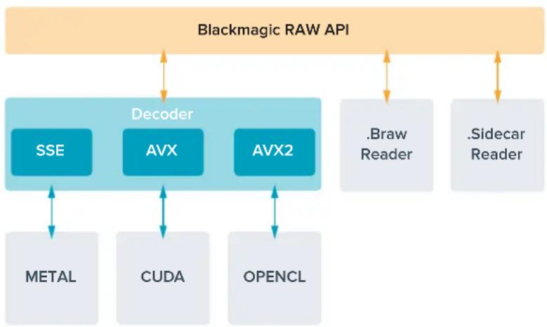
Blackmagic RAW Software Development Kit
The Blackmagic RAW Software Development Kit is an API developed by Blackmagic Design. You can use the Blackmagic RAW SDK to write your own applications to use the Blackmagic RAW format. This SDK library can be used by any developer to add support for reading, editing, and saving Blackmagic RAW files. The Blackmagic RAW SDK includes all the generation 4 and generation 5 color science so you can achieve organic cinematic images across any app that supports it. The Blackmagic RAW SDK supports Mac, Windows and Linux, and is available as a free download from the developer page of the Blackmagic website at www.blackmagicdesign.com/developer
The following diagram illustrates the components of the Blackmagic RAW API:
Record Duration
The table in this section shows approximate record duration in minutes and seconds based on format, project frame rate and flash disk size.
The maximum recording time for a flash disk can vary depending on the data capacity of your USB-C flash disk and the frame rate you choose. It should also be noted that the recording duration for a flash disk can vary slightly between different manufacturers and whether the storage media is formatted as exFAT or Mac OS Extended.
Simple scenes containing less detail tend to require less data than more dense compositions. The values in these tables assume shots with a high complexity, which means you may get slightly longer record times depending on the nature of your shoot.
ULTRA HD
| USB Flash Disk Frame Rate | Blackmagic RAW 3:1 | Blackmagic RAW 5:1 | Blackmagic RAW 8:1 | Blackmagic RAW 12:1 |
| 256GB | Duration Duration Duration | |||
| 23.98 41 mins 68 mins 110 mins 164 mins | ||||
| 24 41 mins 68 mins 109 mins 164 mins | ||||
| 25 39 mins 66 mins 105 mins 157 mins | ||||
| 30 33 mins 55 mins 88 mins 131 mins | ||||
| 50 19 mins | 33 mins 52 mins 79 mins | |||
| 60 16 mins | 27 mins | 44 mins 66 mins | ||
Record Settings Page 2
The second page of the 'record' settings tab contains the following options.
Move through the pages of record settings to find the selling you want to change
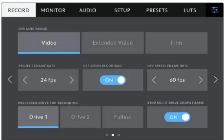
Dynamic Range
Adjust the 'dynamic range' setting by tapping the dynamic range icons. Blackmagic Studio Cameras have three dynamic range settings:
| Video | The 'video' setting is perfect for live to air broadcast and lets you work faster by recording to a high contrast look suitable for direct delivery or minimal post processing. Video uses Rec.709 primaries and has 6 stops over middle gray with another 3 stops in specular highlights. This is a good option if you want an accurate starting point that still has a pleasing gamma curve. |
| Extended Video | The 'extended video' setting is based on Blackmagic Wide Gamut with contrast and saturation applied. The most notable differences to the video mode come from the magenta/green axis having less saturation which is more typical of print film, and even more highlight roll off than video mode which causes highlights to desaturate more. It has a slightly flatter gamma curve that results in less saturation. |
| Film | The 'film' setting shoots video using a log curve that allows you to maintain the greatest dynamic range and maximizes the information in your video signal to help you get the most out of color grading software, such as DaVinci Resolve. |
NOTE When recording Blackmagic RAW using 'film' dynamic range, the image will appear dull and desaturated on your touchscreen. This is because the image file contains a lot of data that hasn't yet been graded to suit a standard display. However you can monitor the video on the LCD, HDMI and SDI output using a display LUT, or look up table, designed to simulate a standard contrast. For more information, refer to the '3D LUTs' section in this manual.
Project Frame Rate
Project frame rate provides a selection of frame rates commonly used in the film and television industry. For example, 23.98 frames per second. This frame rate is normally set to match your playback speed and audio sync used in your post production workflow and delivery requirements.
Eight project frame rates are available, including 23.98, 24, 25, 29.97, 30, 50, 59.94 and 60 frames per second.
NOTE When you coordinate a multi camera recording through ATEM Mini, Blackmagic Studio Cameras will change their frame rate to match the frame rate setting of the ATEM Mini. If you are working with an SDI based ATEM switcher, you will need to set your project frame rate on your camera to match the switcher.
Off Speed Recording
By default, the project and sensor frame rates are matched for a natural playback speed. Tapping the 'off speed recording' switch icon lets you set your sensor frame rate independently.
Off Speed Frame Rate
With 'off speed recording' enabled, tap the arrows next to the 'off speed frame rate' indicator to set your camera's sensor frame rate.
The sensor frame rate sets how many actual frames from the sensor are recorded every second and will affect how fast or slow your video will play back at your set project frame rate.
Preferred Drive for Recording
When a USB flash disk is connected to both USB ports, use this setting to determine which media is recorded to first. The options are 'drive 1', 'drive 2' and 'fullest drive'. Picking either 'drive 1' or 'drive 2' is a matter of personal preference and when the selected drive fills up, your camera will then continue recording on the alternate drive. 'Fullest' can help group files chronologically when shooting a single camera project.
You can override this setting at any time by entering the storage manager and tapping the drive name to set it as active. It's important to note, however, that ejecting and reconnecting drives reverts to the current 'preferred drive for recording' setting.
TIP The 'fullest' setting is based on the percentage that your recording media are filled, rather than their sizes or the amount of data used.
Stop Rec If Drive Drops Frame
Use this setting to configure the behavior of your Blackmagic Studio Camera when dropped frames are detected. When set to 'off,' recording continues with dropped frames. When set to 'on,' your camera stops recording if dropped frames are detected. This can prevent you wasting time shooting unusable footage if you don't spot the dropped frame indicator.
Record Settings Page 3
The third page of the 'record' settings tab contains the following settings.
Timelapse
This setting activates the timelapse feature to automatically record a still frame at the following intervals:
Frames 2-10
Seconds 1-10,20,30,40,50
Minutes 1-10
For example, you can set the camera to record a still frame every 10 frames, five seconds, 30 seconds, five minutes etc.
The timelapse feature offers many creative options. For example, setting a two frame timelapse interval gives your recorded video a high speed effect when played back.
Start recording by pressing the record button. When you press the button again to stop recording, the timelapse sequence is saved as one single clip, matching the codec and frame rate set in your camera. This means you can drop the timelapse sequence into your post production timeline just like any other clip you have recorded.

Timelapse mode is indicated by an icon over the 'record' button
TIP When you record clips in timelapse mode, the timecode counter updates when a frame of video is recorded.
Detail Sharpening
On Blackmagic Studio Camera 4K Plus and Pro, use this setting to sharpen the image. When sharpening is enabled, decrease or increase the level of sharpening by selecting 'default', 'medium' or 'high'.
When enabled, sharpening will be applied to the HDMI and SDI outputs, but will not be recorded via USB-C. This is because you will have more options and greater control over your image using the sharpening tools in DaVinci Resolve.
Apply LUT in File
If you are applying a LUT to the LCD or the HDMI and SDI outputs, the LUT will be embedded into the Blackmagic RAW file you are recording. This means that the LUT will be saved in the header of the file and can easily be applied to the clip in post production without needing to handle a separate file. When the 'apply LUT in file' switch is set to 'on' in the record menu, this clip will open in Blackmagic RAW Player and DaVinci Resolve with the chosen LUT already applied to it. The LUT can then be easily toggled 'on' or 'off' but will always travel with the Blackmagic RAW file as it is written into the clip itself.
DaVinci Resolve also has an 'Apply LUT' switch in the RAW settings palette for enabling or disabling the 3D LUT in the Blackmagic RAW file. The 'Apply LUT' setting in DaVinci Resolve is the same setting as in the camera. This means that when shooting you can direct the colorist to use the LUT by setting it in the camera, but they can switch it off easily in DaVinci Resolve by setting 'Apply LUT' to 'off'.
File Naming Convention
Clips are always recorded to your USB-C flash disk using Blackmagic RAW.
The table below shows an example of the file naming convention:
A001_08151512_C001.mov QuickTime Movie Filename
| A001_08151512_C001.mov Camera Index | |
| A001_08151512_C001.mov | Reel Number |
| A001_08151512_C001.mov | Month |
| A001_08151512_C001.mov | Day |
| A001_08151512_C001.mov | Hour |
| A001_08151512_C001.mov Minute | |
| A001_08151512_C001.mov | Clip Number |
When you are recording camera ISO files from an ATEM Mini switcher, the clips' file name will be determined by the 'record stream' palette in ATEM Software Control. This means that the files can be identified and linked when the ATEM project is opened in DaVinci Resolve.
For more information, please refer to the 'ATEM Mini' manual which can be downloaded from the Blackmagic Design support center at www.blackmagicdesign.com/support
Monitor Settings
The 'monitor' tab lets you adjust status text, overlays, and other monitoring options for your Blackmagic Studio Camera's LCD touchscreen, HDMI output and SDI output for Blackmagic Studio Camera 4K Pro. These menus have two pages of options, which you can cycle through by tapping the arrows at the edge of your camera's touchscreen, or swiping left or right.
LCD, HDMI and SDI Monitor Settings Page 1
The first page of the monitor tab contains identical settings for each output. For example, you can set 'zebra' on for the LCD touchscreen and off for the HDMI and SDI output.
Clean Feed
Tap the 'clean feed' switch in the LCD, 'HDMI' or 'SDI' menus to disable all status text and overlays for that output. The record tally will still be displayed on the LCD when clean feed is applied.
It is a good idea to apply clean feed to outputs you are feeding to your switcher or any external recorders when using a multicam setup.
Your studio camera will display a record tally even in clean feed mode
NOTE LUTs will still be applied to outputs with 'clean feed' enabled. To disable LUTs, disable the 'Display 3D LUT' switch in the 'monitor' menu.
Display 3D LUT
Your Blackmagic Studio Camera can apply 3D LUTs to any output to approximate the look of color graded footage. This is especially useful when recording clips using 'film' dynamic range.
If your camera has a 3D LUT active, use this setting to independently apply that LUT to your LCD touchscreen, HDMI or SDI output.
Tap the 'Display 3D LUT' switch in the 'LCD', 'HDMI' or 'SDI' pages to enable 3D LUTs for those outputs. For details on loading and using 3D LUTs, see the 'LUTs' information in the 'menu settings' section of this manual.
Zebra
Tap the 'zebra' switch in the LCD, 'HDMI' or 'SDI' menus to enable zebra guides for those outputs. For more information on setting zebra levels, see the 'touchscreen controls' section in this manual.
Focus Assist
Tap the 'focus assist' switch in the 'LCD', 'HDMI' or 'SDI' menus to enable focus assist for those outputs. For more information on focus assist and setting focus assist levels, see the 'touchscreen controls' section in this manual.
Frame Guide
Tap the 'frame guide' switch in the 'LCD', 'HDMI' or 'SDI' menus to enable frame guides for those outputs. For more information on frame guides and choosing different guides, see the 'touchscreen controls' section in this manual.
Grid
Tap the 'grid' switch in the 'LCD', 'HDMI' or 'SDI' menus to enable a rule of thirds grid for those outputs. For more information on the rule of thirds grid, see the 'touchscreen controls' section.
False Color
Tap the 'false color' switch in the 'LCD', 'HDMI' or 'SDI' menus to enable false color exposure assistance for those outputs. For more information, see the 'menu settings' section in this manual.
Safe Area Guide
Tap the 'safe area' switch in the 'LCD', 'HDMI' or 'SDI' menus to enable safe area overlay for those outputs. For more information on the safe area guide, see the 'touchscreen controls' section in this manual.
NOTE Use the 'safe area guide' percentage setting in your Blackmagic Studio Camera's 'both' monitoring settings to set the size of the safe area guide.
LCD Monitor Settings Page 2
The second page of your Studio Camera's 'LCD' monitor tab contains settings unique to your LCD touchscreen.
Status text' gives you a clear view of your camera's preview image
Status Text
Set to 'off' to hide the lower third overlays on the LCD touchscreen, leaving only the information necessary to compose or direct a shot. Lower third overlays include the histogram, storage indicators and audio meters. Overlays such as frame guides, grids, focus assist and zebra remain visible if enabled.
Display
Instead of a histogram and audio meters, your camera can display codec and resolution information instead. This can be useful if you prefer to use false color for dialling in exposure, or are recording audio separately and want to display additional information in the space normally used by the histogram and audio meter. Simply tap 'meters' or 'codec and resolution' in the LCD' menu to select your preferred view.
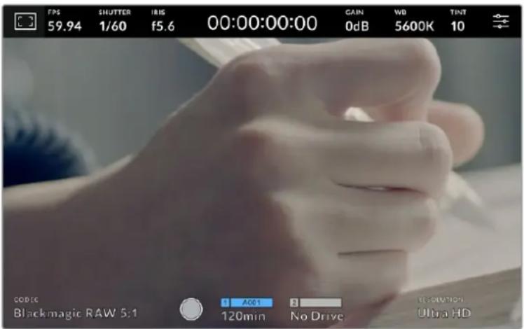
Your Blackmagic Studio Camera can display codec and resolution information in place of the histogram and audio meters
Screen Brightness
Drag the 'screen brightness' slider in the 'LCD' menu left or right to adjust the brightness of your Studio Camera's LCD touchscreen.
HDMI Monitor Settings Page 2
The second page of your 'HDMI' monitor tab contains settings unique to your HDMI output.
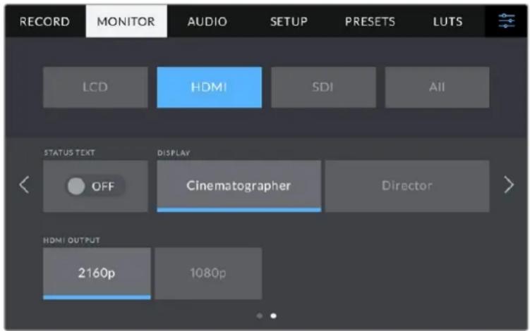
Status Text
Set to 'off' to hide overlays on the HDMI output, leaving only the information necessary to compose or direct a shot. Overlays such as frame guides, grids, focus assist and zebra remain visible if enabled.
Display Status Text For Cinematographer or Director
The LCD touchscreen displays information such as gain, white balance, and aperture that is useful to a camera operator or cinematographer. Your camera's HDMI output, however, can also show information useful for a director or script supervisor who is keeping track of multiple shots or cameras.

Your Blackmagic Studio Camera can display director specific status text on its HDMI output
Setting the status text to 'director' in the HDMI monitor settings changes the status text for that output to show the following information.
FPS
Displays the currently selected frames per second for that camera. If off speed frame rate is disabled, only the project frame rate is shown. If an off speed frame rate is being used, the sensor frame rate is shown, followed by the project frame rate.
CAM
Displays the camera index as set in your camera's slate. For more information, see the 'slate' section.
OPERATOR
Identifies the camera operator as set in your camera's slate. For more information, see the 'slate' section.
DURATION DISPLAY
Displays the duration of the current clip while recording, or the last recorded clip in the following format:
hours:minutes:seconds.
REEL, SCENE, TAKE
Displays the current reel, scene and take. For more information on reels, scenes, takes and their labelling conventions, refer to the 'slate' section.
DYNAMIC RANGE
The bottom left hand corner of the monitor displays the current dynamic range setting being used. 'Film', 'video' or 'extended video' will be displayed.
TIMECODE
The bottom right of the monitor displays your camera's timecode, in the following format: hours:minutes:seconds:frames.
HDMI Output
Your studio camera's HDMI output supports 2160p and 1080p independently of your recording resolution. The video standard will match your camera's project frame rate.
The HDMI output can determine the video format and frame rate supported by other HDMI equipment and sets the output accordingly. For example, if you connect to displays, ATEM switchers and HyperDeck disk recorders that support HD only, your camera will automatically set the HDMI output to 1080p.
If your equipment can accept 2160p, you can set the HDMI output to 2160p or 1080p.
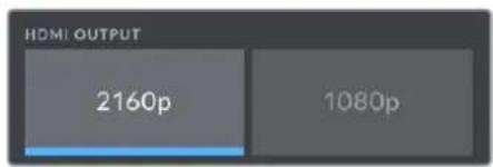
HDMI Output
SDI Monitor Settings Page 2
The second page of Blackmagic Studio Camera 4K Pro's SDI monitor tab contains settings unique to the SDI output.
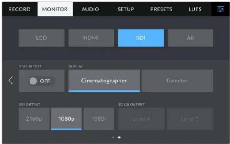
3G-SDI output' options are available when outputting a 1080p signal at 50, 59.94 or 60 fps
Status Text
Set to 'off' to hide the lower third overlays on the SDI output, leaving only the information necessary to compose or direct a shot. Lower third overlays include the histogram, storage indicators and audio meters. Overlays such as frame guides, grids, focus assist and zebra remain visible if enabled.
Display Status Text For Cinematographer or Director
The LCD touchscreen displays information such as gain, white balance, and aperture that is useful to a camera operator or cinematographer. Your camera's SDI output, however, can also show information useful for a director or script supervisor who is keeping track of multiple shots or cameras.
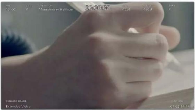
Your Blackmagic Studio Camera 4K Pro can display director specific status text on its SDI output
Setting the status text to 'director' in the SDI monitor settings changes the status text for that output to show the following information.
FPS
Displays the currently selected frames per second for that camera. If off speed frame rate is disabled, only the project frame rate is shown. If an off speed frame rate is being used, the sensor frame rate is shown, followed by the project frame rate.
CAM
Displays the camera index as set in your camera's slate. For more information, see the 'slate' section.
OPERATOR
Identifies the camera operator as set in your camera's slate. For more information, see the 'slate' section.
DURATION DISPLAY
Displays the duration of the current clip while recording, or the last recorded clip in the following format:
hours:minutes:seconds.
REEL, SCENE, TAKE
Displays the current reel, scene and take. For more information on reels, scenes, takes and their labelling conventions, refer to the 'slate' section.
DYNAMIC RANGE
The bottom left hand corner of the monitor displays the currently applied LUT, if applied to that output. If no LUT is applied, 'film' or 'video' dynamic range is displayed.
TIMECODE
The bottom right of the monitor displays your camera's timecode, in the following format: hours:minutes:seconds:frames.
SDI Output
Blackmagic Studio Camera 4K Pro's SDI output supports 2160p, 1080p and 1080i independently of your recording resolution. When set to 2160p or 1080p the video standard will match your camera's project frame rate.
Interlaced HD is available on your SDI output when your project frame rate is set to 50p, 59.94p or 60p and this will be sent as 1080i50, 59.94 or 60 accordingly.
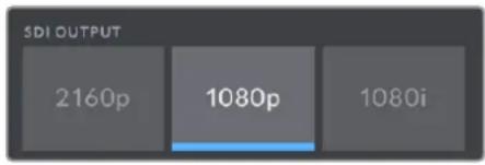
SDI Output
3G SDI Level A/B
You can change the 3G-SDI output standard to maintain compatibility with 3G-SDI equipment that supports either level A or level B 3G-SDI. This option is available when outputting 1080p at 50, 59.94 or 60 fps via SDI out.
All Monitor Settings Page 1
Monitor settings that affect all of your studio camera's outputs are grouped within the 'all' menu, or 'both' on Blackmagic Studio Camera 4K Plus. For example, setting 'safe area guide' to 90% in this menu will set the safe area guide to 90% for your camera's LCD, plus HDMI and SDI outputs depending on which model studio camera you are using.
There are two pages of 'all' settings. The first page of your studio camera's 'all' monitor tab contains the following settings.
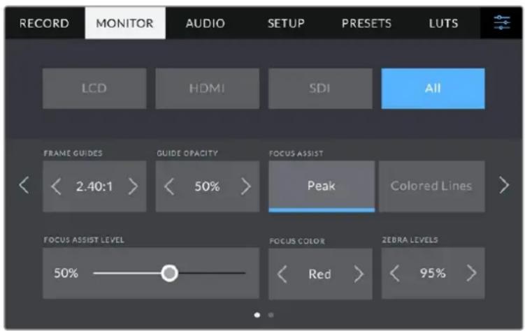
Frame Guides
Tap the left or right arrows in the 'frame guides' menu setting to cycle through frame guide options for all outputs on your studio camera. The options are detailed in the 'touchscreen controls' section of this manual, and are also accessible from the LCD monitoring menu in your LCD touchscreen head up display. It's worth noting that you can individually select whether frame guides will appear on your LCD touchscreen, HDMI output and SDI output in their respective 'monitor' menus.
Guide Opacity
Tap the left or right arrows in the 'guide opacity' menu setting to choose the opacity of the areas blocked out by frame guides on your LCD touchscreen, HDMI and SDI outputs. The options are 25% , 50% , 75% and 100% .
Focus Assist
Your studio camera features 'peak' and 'colored lines' focus assist modes.
Peak
When 'peak' style focus assist is selected, areas of the shot that are in focus are heavily sharpened on your LCD touchscreen or SDI and HDMI outputs, but not in the recorded image itself. This causes focused parts of your shot to 'pop' out of the softer background on screen. As no additional overlays are used, this can be a very intuitive way to tell when focus is dialled in, especially when the subject you're focusing on is physically well separated from other elements in shot.
Colored Lines
When 'colored lines' style focus assist is selected, a colored line is superimposed around the parts of the image that are in focus. This can be a little more intrusive than 'peak' style focus assistance as the lines are drawn over your image. However, in busy shots with a lot of visible elements, it can be a precise focus aid.
Focus Assist Level
The focus assist level on the LCD is set by the peaking dial on the right side of the camera. You can override it by swiping the slider left and right. It is better to view the live image whilst adjusting the dial, allowing for finer control of the result.
It's worth noting that setting the focus assist level does not determine whether focus assistance is enabled on your studio camera's LCD touchscreen, HDMI or SDI outputs. You can still turn focus assistance on or off individually for each output in the 'LCD', 'HDMI' or 'SDI' monitor menus.
TIP The optimum level of focus assistance varies shot by shot. When focusing on actors, for example, a higher level of focus assistance can help resolve edge detail in faces. A shot of foliage or brickwork, on the other hand, may show distracting amounts focus information at higher settings.
Focus Color
Use this setting to change the color of focus line overlays when using 'colored lines' style focus assistance. Changing the focus line color can make it easier to tell focus assistance lines apart from your image. The available options are 'white,' 'red,' 'green,' 'blue' and 'black.'
Zebra Levels
Set the exposure level that zebra appears at by tapping the arrow icons on either side of this setting. Zebra level is adjustable in five percent increments between 75 and 100 percent exposure. For more information, see the 'zebra' guide in the 'touchscreen controls' section of this manual.
All Monitor Settings Page 2
The second page of your Studio Camera's 'all' monitor tab contains the following options:
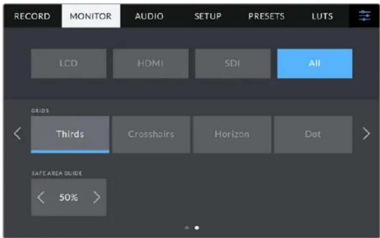
Grids
To set which combination of grids and crosshairs you want to display on your studio camera's LCD touchscreen, HDMI and SDI outputs, tap the 'thirds,' 'crosshairs,' or 'center dot' options in this setting. For more information, see the 'grids' guide in the 'touchscreen controls' section earlier in this manual.
Safe Area Guide
To adjust the size of the safe area overlay on your studio camera's LCD touchscreen, HDMI and SDI outputs, tap the arrows to the left and right of the percentage displayed in this setting. This percentage indicates the size of the safe area in relation to the image frame. Most broadcasters require a 90% safe area.
Audio Settings
The 'audio' tab lets you adjust the audio input and monitoring settings on your camera.
Audio settings for the camera are spread over two pages and divided between channels 1 and 2. You can map each audio channel to a different source, as well as adjusting various settings such as gain control.
Audio Settings Page 1
The first page of the 'audio' tab contains the following settings.
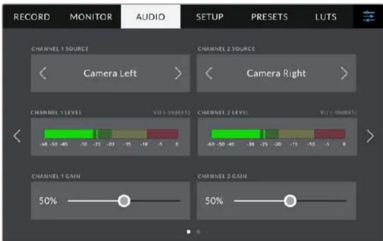
Channel Source
Use the 'channel 1 source' and 'channel 2 source' buttons to select your audio source for each audio channel. Below is a description of each channel source setting.
- Camera Left or Right
Records from your camera's internal microphones.
- Camera Mono
Creates a single audio channel from your Blackmagic Studio Camera's built in microphone's left and right channels.
XLR Line
Uses Blackmagic Studio Camera 4K Pro's XLR input to record line level audio.
XLR Mic
Records mic level audio from Blackmagic Studio Camera 4K Pro's XLR input. If phantom power is enabled and you have the XLR input set to 'mic' you'll also see a +48V indicator here. It is also important to ensure that the 48V switch gets turned 'off' when you disconnect your phantom powered microphone.
3.5mm Left - Line
Uses only the left channel of the 3.5mm input as line level audio.
3.5mm Right - Line
Uses only the right channel of the 3.5mm input as line level audio.
3.5mm Mono - Line
Creates a mono mix of the left and right channel from the 3.5mm input as line level audio.
3.5mm Left - Mic
Uses only the left channel of the 3.5mm input as mic level audio.
3.5mm Right - Mic
Uses only the right channel of the 3.5mm input as mic level audio.
3.5mm Mono - Mic
Creates a mono mix of the left and right channel from the 3.5mm input as mic level audio.
None
Disables your audio channel.
NOTE When selecting the 3.5mm input as an audio source, the channel 1 and channel 2 sources both need to be line level or mic level. This means that if you select '3.5mm left - line' as your channel 1 source, the available options for the 3.5mm input on channel 2 will all be line level: '3.5mm left - line', '3.5mm right - line' and '3.5mm mono - line'. The mic level options will be grayed out.
Channel 1/2 Level
The level meters help you set the correct audio level.
Channel 1/2 Gain
Use these sliders to adjust the recording levels of your chosen channel 1 and 2 sources.
Audio Settings Page 2
The second page of the 'audio' tab contains the following settings.
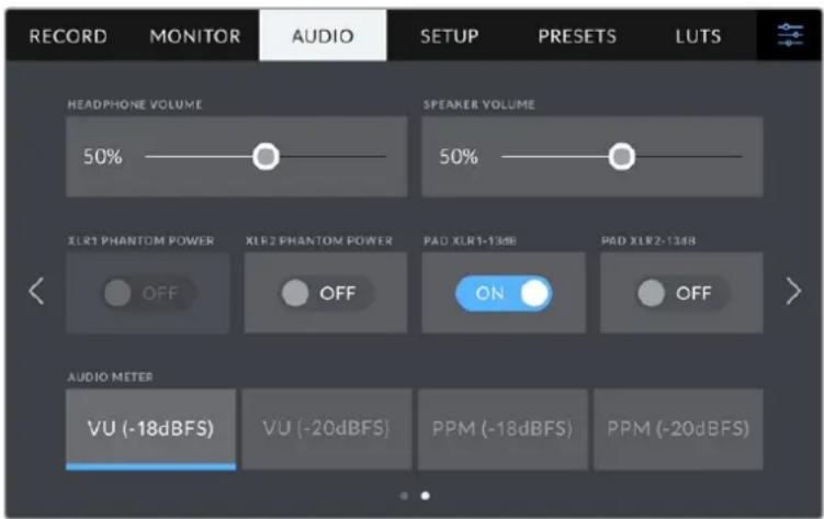
Headphones Volume
This slider adjusts the output levels for headphones and headsets connected to the 3.5mm or 5 pin XLR headset jacks. Move the audio slider left or right to adjust levels.
Speaker Volume
This slider adjusts the output levels for the built in speaker. Move the audio slider left or right to adjust levels.
XLR Phantom Power
Blackmagic Studio Camera 4K Pro's XLR input can provide 48V phantom power so you can use microphones that aren't self powered. When your camera is set to 'XLR' audio input, simply tap the 'phantom power' switch icon to enable phantom power. Blackmagic Studio Camera 4K Pro has two XLR inputs and separate phantom power switches for each input.
Audio Meters
You can select from VU or PPM meter types. While the VU meter has now become standardized, PPM and loudness meters provide scaling systems and measurements for perceived loudness.
·vu
This meter averages out short peaks and troughs in your audio signal. It's mostly used to monitor peaks in a signal, however, because of its averaging capability it can also be used to monitor the perceived loudness of your audio.
- PPM
This meter displays a "peak hold" feature that momentarily holds the signal peaks, and a slow fall back so you can easily see where your audio is peaking.
NOTE It is standard practice to plug in your XLR cable before switching phantom power on. It is also important to switch phantom power to 'off' when you no longer have a phantom powered microphone connected. Connecting equipment that doesn't require phantom power when still in phantom power mode can damage your equipment, as the camera outputs a charge when in this mode. Phantom power can also take quite a while to discharge after switching it off.
Please be aware that you should wait a few minutes when switching off phantom power before plugging in any other microphones or XLR audio equipment.
Setup Settings
The 'setup' tab contains your Blackmagic Studio Camera's identification settings, software version, function button settings and other camera settings not directly linked to recording or monitoring.
The first page of your camera's 'setup' tab contains the following settings.

Date and Time
Set your camera's date and time by tapping the 'date and time' setting. The date format is year, month, day and the time format is 24 hour. Date and time are also used for time of day timecode if an external timecode source is not connected.
Language
Blackmagic Studio Cameras support 11 popular languages: English, Chinese, Japanese, Korean, Spanish, German, French, Russian, Italian, Portuguese and Turkish.
The 'select language' page will appear on initial start up and after you update the camera's internal software.
To select your language:
1 Tap on the 'language' in the list
2 Select 'update' to return to the setup menu.
Shutter Measurement
Select whether to display shutter information as 'shutter angle' or 'shutter speed'. When using shutter angle, the shutter conforms to the frame rate. When using shutter speed, the shutter is given an absolute, real time value and isn't connected to your frame rate.
For example, when using a shutter speed of 1/48th of a second, motion blur will remain consistent regardless of the frame rate as the measurement is always the same in real time. Alternatively, a shutter angle of 180 degrees is directly applied to each frame, and therefore influenced by the amount of frames recorded each second. This means motion blur will vary based on the frame rate you are using.
It's worth mentioning the minimum shutter speed value corresponds to the frame rate. This means 1/24th of a second is the minimum available shutter speed when shooting at 24p and 1/50th is the minimum shutter speed available for 50p.
Flicker Free Shutter based On
Use this setting to change the mains power frequency your camera uses to calculate flicker free shutter settings.
When shooting under lights, your shutter can affect the visibility of flicker. Your Blackmagic Studio Camera automatically calculates a flicker free shutter value for current frame rate and suggests up to three shutter values. Shutter values are affected by the frequency of local mains power supply used to drive those lights. In most PAL countries, the frequency is 50Hz , while NTSC countries typically use 60Hz power. Tap '50Hz' or '60Hz' to set the frequency for your region.
Image Stabilization
Blackmagic Studio Camera 4K Plus and 4K Pro has an 'image stabilization' option to enable or disable image stabilization on lenses without a physical switch.
Timecode Drop Frame
Use the 'timecode drop frame' option to use drop frame timecode when using NTSC project frame rates of 29.97 and 59.94. Drop frame timecode skips a small number of frames from the timecode at set intervals. This keeps your project timecode accurate despite each second not containing a whole number of frames at NTSC frame rates.
Setup Settings Page 2 on Blackmagic Studio Camera 4K Pro
The second page of the 'setup' tab contains the following settings on Blackmagic Studio Camera 4K Pro.
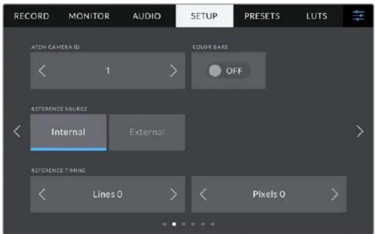
ATEM Camera ID
If you're using more than one Blackmagic Studio Camera 4K Pro with an ATEM Switcher and want your cameras to receive tally signals from the switcher, you'll need to set their ATEM camera ID numbers. This ensures the switcher sends the tally signal to the correct cameras. The camera ID number can be set to a value of 1-99 by tapping the left or right buttons. The default setting is 1.
Color Bars
Outputting color bars rather than a preview image can be useful when connecting your Studio Camera 4K Pro to a switcher or external monitor. The appearance of your studio camera's color bars on your switcher or monitor confirms the connection, and you can perform basic monitor calibration based on the colors of the bars. To turn on color bars for all outputs on Blackmagic Studio Camera 4K Pro, including the LCD touchscreen, simply tap the 'color bars' switch icon.
Reference Source
Blackmagic Studio Camera 4K Pro can lock to an internal or external reference source. When connecting to an ATEM switcher directly using SDI, setting this to 'external' will genlock the camera to the switcher's 'program return' feed via the camera's SDI input.
Reference Timing
These settings allow you to manually adjust the reference timing on a line or pixel basis. Simply tap the arrow icons on either side of the "lines" and "pixels" settings to make adjustments.
Setup Settings Page 3 on Blackmagic Studio Camera 4K Pro
The third page of the 'setup' tab contains the following settings for Blackmagic Studio Camera 4K Pro.
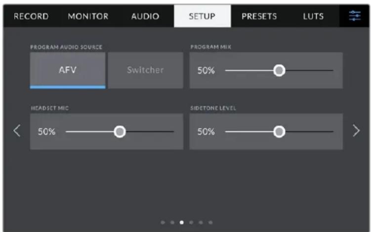
Program Audio Source
When connected to an ATEM switcher, setting 'program audio source' to 'switcher' prioritizes the program return audio as your input source to be mixed with talkback when monitoring using headphones or a headset. This is useful when you are not feeding the switcher audio from your camera but you still want to listen to the program feed from the switcher via the 'SDI in' port. Setting 'program audio source' to 'AFV', or audio follows video, prioritizes audio that is being displayed on your LCD. That means if the camera's LCD is displaying what the camera is seeing, you will hear that audio source, but if you have engaged the program return feed, your audio source will be coming from the program audio feed.
Program Mix
This setting changes the balance of camera sound to talkback sound. The headphones will output audio following what is displayed on the LCD. For instance, if you are in camera view, camera audio is heard. If you are in program view, program audio is heard. The default setting is 100% .
Headset Mic
Move this volume slider left or right to increase or decrease audio microphone input levels. The default setting is 50% .
Sidetone Level
Adjust this slider to set the volume of your own voice mic in your headset.
TIP Blackmagic Studio Camera 4K Pro has a powerful talkback mic preamp so care should be taken when adjusting your mic gain or sidetone levels with 3.5mm mini jack consumer earbuds or headsets. Often these are not very well electrically shielded which can cause crosstalk. If you do encounter this then setting your sidetone very low will cancel out the feedback being caused by your headset.
Setup Settings Pages 4 and 2
The fourth page of the 'setup' tab on Blackmagic Studio Camera 4K Pro contains the following settings. These settings are on the second page for Blackmagic Studio Camera 4K Plus.
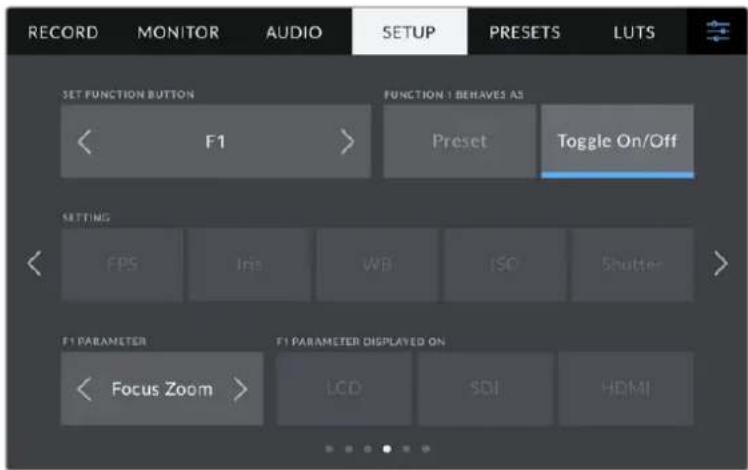
Set Function Button
Next to your studio camera's LCD touchscreen, you'll notice three function buttons, 'F1', 'F2' and 'F3'. These are mappable to frequently used features and are quickly accessible when operating your camera live and want to avoid using the touchscreen.
1 Button 2 Behavior 3 Setting 4 Parameter
Function Button Behaves as Preset or Toggle
Once you have selected the function button you want to map, you can select a behavior.
The available options are:
Preset
When set to this behavior, pressing a function button will recall a combination of a setting and a parameter.
To set a preset, select the setting you want to use from the 'setting' menu, and adjust that setting by tapping the arrow icons on either side of the 'parameter' menu.
For example, to set the F1 button to recall a preset white balance, use the 'set function button' arrows to select 'F1', select the 'preset' behavior, tap the 'WB' setting, and tap the arrows on either side of the 'parameter' menu until you get to WB '5600K' and Tint '10'
Toggle On/Off
When set to this behavior, pressing a function button will toggle a particular setting on or off. The 'setting' menu is grayed out in this mode. Instead, tap the left or right arrows in the parameter menu to scroll through the available options. These are 'OIS optical image stabilisation', 'focus zoom', 'focus', 'iris', 'record', 'clean feed', 'display LUT', 'frame guides', 'focus assist', 'false color', 'zebra', 'grid', 'safe area guide', 'off speed rec', 'status text', 'color bars', 'push to talk' and 'none'.
Using the 'toggle on/off' behavior also lets you select the output this setting applies to. Simply tap any combination of LCD, 'HDMI' and 'SDI' to select. If the output for an option is not available, such as 'focus zoom', the 'HDMI', and 'SDI' settings are disabled.
Setup Settings Pages 5 and 3
The fifth page of the 'setup' tab on Blackmagic Studio Camera 4K Pro contains the following settings. This is the third page for Blackmagic Studio Camera 4K Plus.
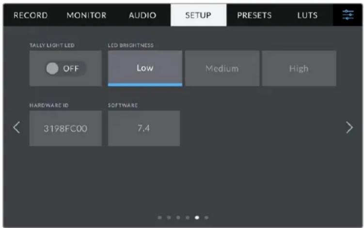
Tally Light LED
In some shooting environments, for example a dimly lit location or an intimate theater performance, you may want to disable the tally light on your camera. To disable the tally light, simply set 'tally light LED' to 'off'. When disabling the tally LED, this will also disable the back light LEDs in all buttons and status lights.
LED Brightness
To set the brightness of the tally light LED, tap 'low,' 'medium,' or 'high'. This will also change the brightness of all back light LEDs on buttons and status lights.
Hardware ID
The 'hardware ID' indicator displays an 8 character identifier for your Blackmagic Studio Camera. This is unique to each camera. A longer, 32 character version of this ID is also included in the metadata for Blackmagic RAW. This can be useful for identifying which footage came from a particular camera.
Software
Displays the version number of currently installed software. See the 'Blackmagic Camera Setup Utility' section for more information on updating software.
Setup Settings Pages 6 and 4
The sixth page of the 'setup' tab on Blackmagic Studio Camera 4K Pro contains the following settings. This is the fourth page on Blackmagic Studio Camera 4K Plus.
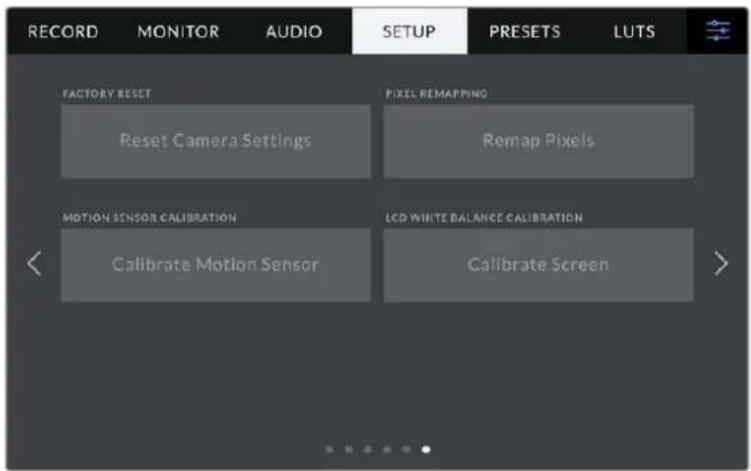
Factory Reset
To reset the camera to its default factory settings, tap the 'reset camera settings' button. On the confirmation page, tap 'reset' to confirm this action. Your camera erases any stored LUTs and preset, and resets all settings. It is a good practice to export your presets to a USB flash drive as a backup before performing a factory reset. After a factory reset, you can restore your preset quickly by importing them from the flash drive. It is important to note that a factory reset also resets the horizon meter, so you should recalibrate the motion sensor after a factory reset to help ensure its accuracy.
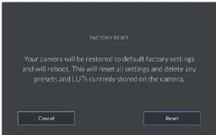
When selecting 'reset' you will be prompted to confirm your action
Pixel Remapping
The CMOS sensor used in your Blackmagic Studio Camera is made up of millions of pixels that respond to light. Some pixels can change in brightness over time following sensor calibration in the factory. As a result, they become more visible and become what is known commonly as hot pixels. All camera sensors, regardless of manufacturer, will develop hot pixels.
To solve this, we have a calibration feature built into the camera which you can run if you see any hot pixels in the image.
To begin this process, simply put on the lens cap and run the pixel remapping feature by tapping the 'remap pixels' button. The process takes approximately one minute to complete.
Motion Sensor Calibration
To calibrate the horizon meter, place your camera on a surface you know is level and tap the 'calibrate motion sensor' button. It is essential that you keep the camera stable during calibration. The process takes approximately five seconds to complete.
LCD White Balance Calibration
To perform LCD white balance calibration, adjust the 'LCD temperature' and 'LCD tint' controls so that the two reference patches look neutral. After you change the settings, you can use the 'reset' button to return the controls to the factory calibration. The 'restore' button brings back your new settings, which helps you compare the appearance before and after calibration. When the LCD shows an accurate white balance, save your settings.

Presets
The 'presets' tab lets you save and recall up to 12 collections of settings. This is very useful when one camera is used for multiple projects. For example, you may use your camera for a variety of different shoots with very different settings between types of projects. Your camera's 'presets' function lets you save the setup for a particular project or type of shoot and come back to it quickly and easily when required. You have 12 preset slots to use.
You can also import and export presets. Simply set up one Blackmagic Studio Camera to suit your project, then export that preset for all the other Blackmagic Studio Cameras on your production.
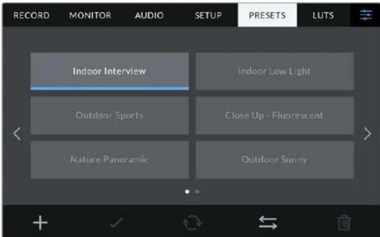
The presets tab allows you to quickly switch between settings that you have saved
Preset buttons
The button icons along the bottom of the 'preset' menu correspond with the following functions.


Add Load Update Manage Delete
Saving and loading presets
To create a new preset, tap the 'add' icon. This opens a touch keyboard on your LCD where you can name your preset. Enter a name and tap 'update' to save all of your current settings to that preset.
If your camera already has a preset loaded with the same name, you can choose to overwrite the existing preset or keep both.
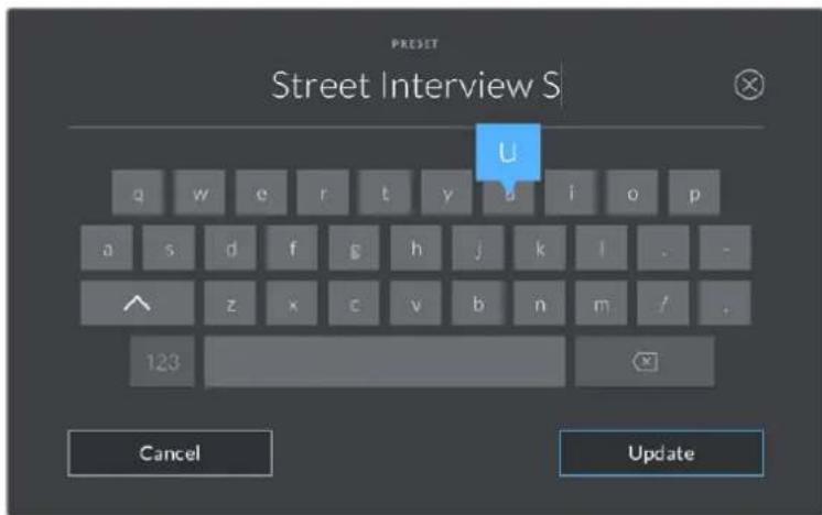
Enter a name for your preset by tapping the 'add' icon in the preset tab and using the touch keyboard
Once you have a preset saved, tap its name in the preset menu to select it. To load a preset, tap the 'load' icon.
Select a preset and tap the 'load' icon to load it. Select presets will appear solid blue, while currently loaded presets have a blue line along the bottom of their icon
You can update a preset by tapping the 'update' icon. This will bring up a prompt asking you if you want to update the preset with your studio camera's current setting. Tap 'update' to confirm.
Importing Presets
To import a preset from a USB-C flash disk, tap the 'manage' icon at the bottom of the 'presets' menu. Tap 'import presets', then tap 'import' to confirm. This brings up the presets import screen. If your preferred preset is not on the active drive, switch between recording media by tapping a media button at the top of the touchscreen.
Your camera searches the root directory and 'presets' folder on your selected media, and lists available presets. Any presets you have saved elsewhere are not visible.
Tap a preset to select it, then tap 'import' to confirm your selection and copy it to the next available slot on the camera.
NOTE If all 12 of your camera's preset slots are full, the import menu is unavailable, and you need to delete an existing preset to make room.
If the preset you want to import has the same name as a preset already saved to your camera, you can choose to overwrite the existing preset or keep both. At the top right of this screen, you'll see the number of remaining empty preset slots available on your camera. You are able to import as many presets as you have free slots on your camera.
Exporting presets
To export a preset to a USB-C flash disk, tap the preset you want to export, then tap the 'manage' button. Tap 'export selected preset', then tap the media where you want to export the preset. If a preset with the same name is already present, choose whether to overwrite the preset or keep both. The camera exports the preset to a 'presets' folder.
Deleting presets
To delete a preset, select it and tap the 'delete' icon. When you are prompted to confirm your choice, tap 'delete'.
LUTs
The 'LUTs' menu lets you import, export and apply 3D LUTs to your LCD, HDMI and SDI outputs.
Select a 3D LUT using your camera's LUTs tab
Introducing 3D LUTs
3D LUTs can be applied to images on your camera's LCD touchscreen, HDMI and SDI output. LUTs work by telling your camera what color and luminance output to show for a particular color and luminance input. For example, a LUT may tell your camera to display a vibrant, saturated blue when it receives a relatively dull blue input. This can be useful when shooting Blackmagic RAW footage, or using 'film' dynamic range, both of which have an intentionally undersaturated, 'flat' appearance. By applying a LUT, you can get an idea of what your footage will look like after it has been graded.
It is easy to create 3D LUTs using DaVinci Resolve or other color correction software, and LUTs are available online from a variety of sources. Up to 10 17 point or 33 point 3D LUTs up to 1.5 megabytes each can be stored on the camera. Once loaded, you can choose to display a given LUT on your camera's LCD touchscreen, HDMI and SDI output.
Your Blackmagic Studio Camera supports 33 point 3D LUTs in .cube format created in DaVinci Resolve and 17 point 3D LUTs converted to Resolve .cube format via LUT conversion programs. Your camera processes 3D LUTs using high quality tetrahedral interpolation.
TIP For more information on displaying LUTs, see the 'monitor settings' section in this manual.
Built-in LUTs
A number of built in LUTs are provided that allow you to preview different looks when shooting in 'film' dynamic range or Blackmagic RAW.
Each camera provides LUTs that are specific to Gen 5 color science or the camera sensor:
Film to Extended Video
Displays a wider dynamic range than the 'film to video' LUT, and applies a mild contrast change with a smooth roll off in the highlights.
Film to Rec 2020 Hybrid Log Gamma
Displays a gamma curve that is suitable for HDR screens and compatible with standard dynamic range screens.
Film to Rec 2020 PQ Gamma
Displays a gamma curve that is based on what we can perceive with our eyes, for efficient encoding of HDR images.
Film to Video
Similar to the REC 709 color standard for high definition video, and has a high level of contrast and saturation. You may find this setting useful when using Blackmagic Studio Camera alongside other broadcast cameras using the REC 709 color space.
LUTs buttons
Button icons along the bottom of the 'LUTS' screen correspond to the following functions:


Load Media Manage Delete
Importing LUTs
To import a 3D LUT, tap the 'manage' icon at the bottom of the 'LUTs' menu. Tap 'import LUT', then tap 'import' to confirm. This brings up the LUT import screen. If your preferred 3D LUT is not on the active drive, switch between recording media by tapping a media button at the top of the touchscreen. You can import LUTs from a USB-C flash disk.
Your camera searches the root directory and '3DLUTs' folder on your selected media, and lists available LUTs. Any LUTs you have saved elsewhere are not visible.
Tap a LUT to select it, then tap 'import' to confirm your selection and copy it to the next available slot on the camera.
NOTE If you want to import a new LUT but all 10 3D LUT slots are full, you need to delete an existing LUT to make space.
If the LUT you want to import has the same name as a LUT already saved to your camera, you can choose to overwrite the existing LUT or keep both. At the top right of this screen, you'll see the number of remaining empty LUT slots available on your camera. You are able to import as many LUTs as you have free slots on your camera.
NOTE If you have trouble importing a LUT, it may be the wrong size. You can use a LUT editor like Lattice to check its size, or open it in any text editor on your computer. Next to the tag 'LUT_3D_SIZE' is a number indicating the LUT's size. If this value is not 17 or 33, you can use Lattice to resize your 3D LUT to 17 points.
Applying a LUT
Once you have a LUT saved onto your camera, tap it in the LUT menu to select it, and tap the 'load' icon. This enables the LUT for all outputs on your camera. To display the loaded LUT on your camera outputs, switch on 'display LUT' in the monitor menu. See the 'monitor settings' section for more information.
Exporting LUTs
To export a LUT to a USB-C flash disk, tap the LUT you want to export, then tap the 'manage' button. Tap 'export selected LUT', then tap the media where you want to export the LUT. If a LUT with the same name is already present, choose whether to overwrite the LUT or keep both. The camera exports the LUT to a '3DLUTs' folder.
Deleting LUTs
To delete LUTs you are no longer using or make room for more, select the LUTs you want to delete and tap the delete icon. When you are prompted to confirm you choice, tap 'delete'.
Embedded 3D LUTs
When a 3D LUT is used while shooting Blackmagic RAW on Blackmagic Studio Camera, the selected LUT will be embedded into the Blackmagic RAW file that you are recording. The 3D LUT is actually saved with your recorded files in the header of the .draw file, and can easily be applied to footage in post production without needing to handle a separate file.
So when Blackmagic RAW files are delivered to an editor or colorist, they will be able to easily access the LUT that was used while filming, which greatly reduces the possibility that the wrong 3D LUT could be applied to a clip. They can then choose whether to apply the 3D LUT when editing or color grading the footage, and can disable the 3D LUT at any time.
When the 'apply LUT in file' switch is set to 'on' in the record menu, the recorded clip will open in Blackmagic RAW Player and DaVinci Resolve with the chosen 3D LUT already applied to it.
The 3D LUT can then be easily toggled 'on' or 'off' but will always travel with the Blackmagic RAW file as it is written into the clip itself. DaVinci Resolve also has an 'Apply LUT' switch in the RAW settings palette for enabling or disabling the 3D LUT in the Blackmagic RAW file.
The 'Apply LUT' setting in DaVinci Resolve is the same setting as in the camera. This means that when shooting you can direct the colorist to use the LUT by setting it in the camera, but they can switch it off easily in DaVinci Resolve by setting 'Apply LUT' to 'off'.
Using the Sun Hood
The sun hood helps you to see the screen in bright or sunny conditions. To attach the sun hood, place its top edge along the top ridge of the Blackmagic Studio Cameras LCD and hinge it down until it clicks into place.
Place the top edge of the sun hood into the slots above the LCD and lower the hood into position. A latch underneath the LCD will secure the hood to the camera. When removing the sun hood, press the latch to release the hood and then lift the hood away from the camera.
Once attached, open the top shade completely, allowing for the side flags to spring open then let the top rest on the flags.
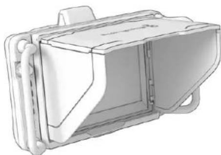
When the top shade is opened, the side flags will also open
The sun hood provides additional protection for the 7" screen, and can be removed quickly and easily. If you want to close the sun hood, fold down the side flags first, then lower the top shade until it clicks into its frame.
To remove the hood, press the latch on the bottom of the frame to release it and then gently lift away from the camera.
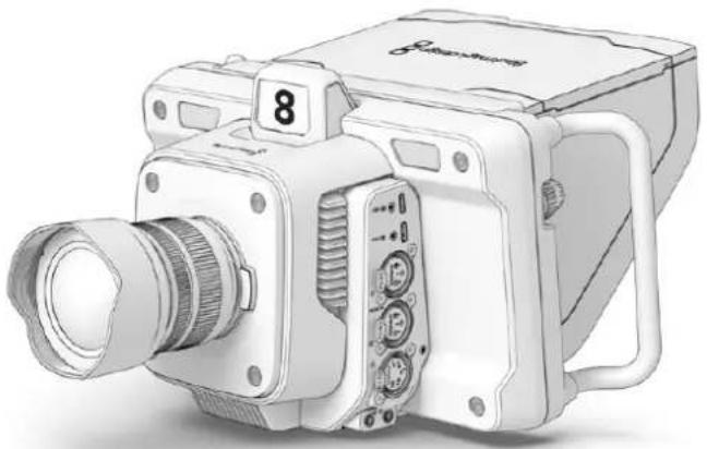
The sun hood helps protect the screen and provides shade in bright conditions
Blackmagic Zoom and Focus Demands
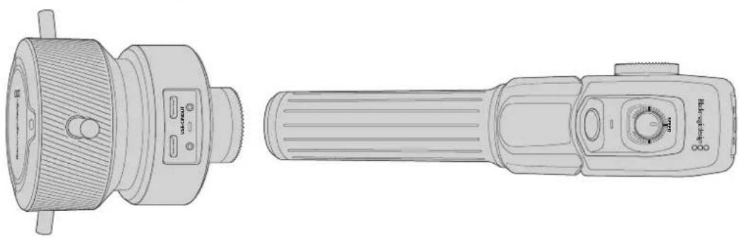
Blackmagic Zoom Demand and Blackmagic Focus Demand are optional accessories for controlling focus and zoom when using compatible zoom lenses. Any active Micro Four Thirds lens will work with Blackmagic Focus Demand. With more than fifty micro four thirds lenses available, that gives you many options that allow for focus control from your tripod handles when used with Blackmagic Studio Cameras.
Each unit attaches to a tripod handle on your tripod or camera pedestal. This lets you control focus and zoom while simultaneously panning and tilting the camera using both hands. Additional buttons and controls let you refine the speed and sensitivity of the zoom control, engage talkback, monitor program return and more.
Connecting and Attaching to your Camera
Attaching to Tripod Handles
Each unit attaches to a tripod handle via their mounting brackets. Attach each unit to the brackets via their rosette mounts.
To attach the demand units to their brackets, simply connect them together via their rosette mounts and secure them by tightening the fastening knob.
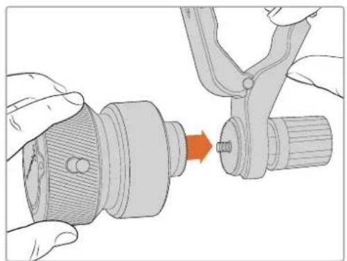
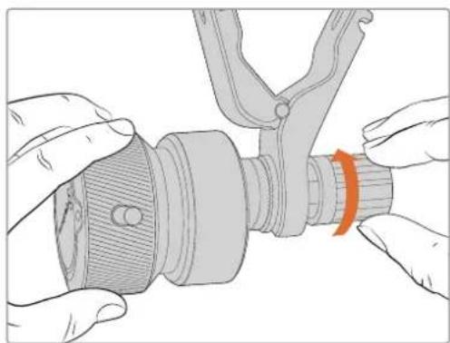
1 Place the zoom demand or focus demand against their bracket's rosette mount.
2 Tighten their fastening knob so the demand units are firmly attached to their brackets.
Now that the units are attached to the brackets, you can attach the brackets to the tripod arms. One end of each bracket contains a 'T' shaped latch that hinges into a slot and is then tightened.
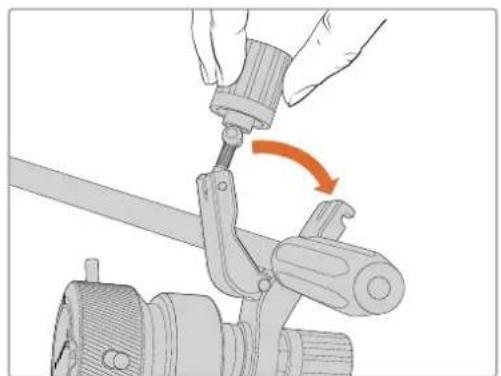
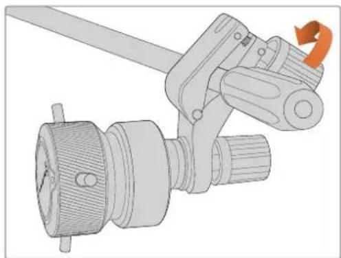
1 Loosen the latch by unscrewing the latch knob in a counterclockwise motion. This will release the 'T' shaped latch.
2 With the latch open, place the bracket onto the tripod arm and clamp the bracket shut by closing the latch into its fastening slot. Rotate the bracket to your preferred position on the tripod arm.
3 Tighten the latch knob to secure the bracket to the tripod arm.
Connecting to Your Camera
Blackmagic Focus and Zoom Demands have two USB-C ports. This lets you use one unit individually, or both units together.
Each unit is supplied with a 1 meter long USB-C cable which is connected directly from either of your studio camera's USB-C expansion ports to the demand unit's 'in' port.
If you are using both demand units, daisy chain them together by connecting the first unit to the second unit via USB-C.

Daisy chaining allows for both units to be controlled using one USB port on your studio camera, letting you use the second port for an external USB flash disk. For example, connect a USB-C cable into either of the camera's expansion ports A or B and connect the other end of the cable into the focus demand's 'in' port. With a second cable, plug the focus demand's 'out' port into the zoom demand's 'in' port.
The USB-C cable has locking screws on each end to secure the connectors to each unit, preventing accidental disconnection. You don't have to use the locking screws, but they are helpful for studio setups where the units are always connected to your studio camera.
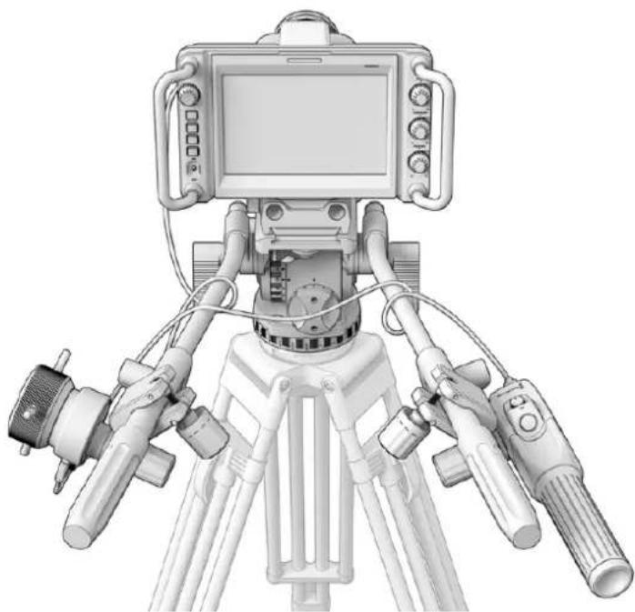
The Blackmagic Focus and Zoom Demands let you control focus and zoom without looking away from the screen
Using Blackmagic Focus Demand
This section describes the features and connectors on Blackmagic Focus Demand.
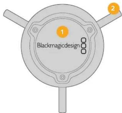
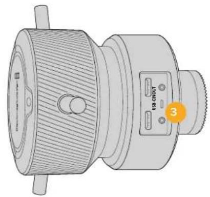
1 Control Knob
Rotate the focus wheel clockwise to focus on subjects closer to the lens, or counterclockwise to focus on subjects further away. You can change the focus direction in the menu by setting it either 'forward' or 'reverse'.
TIP If you are also using a Blackmagic Zoom Demand, press the quick zoom button to magnify the image as you focus using the focus demand.
2 Control Pins
These three pins expand the diameter of the control surface to let you make finer focus adjustments with the tip of a finger.
3 USB ports
Allows for connecting the focus demand to the camera and daisy chaining to the zoom demand. The 'in' port is also used for updating the internal software via the Blackmagic Camera Setup utility.
Using Blackmagic Zoom Demand
The controls on the Zoom Demand are mappable through the Camera settings. To change the button functions, refer to the 'setup settings' chapter in the 'settings' section.
The following commands are set as default:
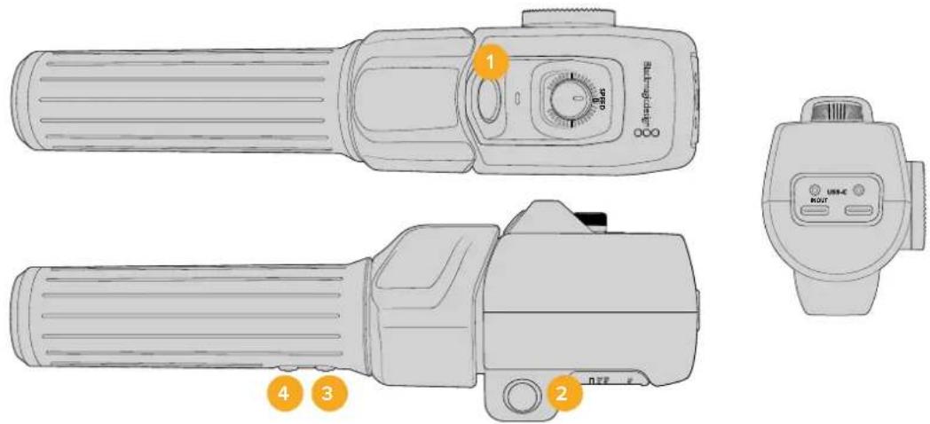
1 Zoom F1
This is the zoom function button 1. By default, it is mapped as a 'record' button for recording to an external drive connected to an available USB-C port on your Blackmagic Studio Camera.
2 Zoom F2
This is the zoom function button 2. On the other side of the controller is an identical button that performs the same function, allowing for left and right handed control. By default, it is set as a quick zoom function which instantaneously punches into the live image.
NOTE The quick zoom feature is only visible on the Blackmagic Studio Camera's LCD and will not be visible on the output video connected to a switcher or recorder.
3 Zoom F3
This is the zoom function button 3. On Blackmagic Studio Camera 4K Pro, the default action for this button is set to program return. This would normally be a switcher's program return feed, but can be any SDI signal connected to your camera's SDI input.
On Blackmagic Studio Camera 4K Plus, the default action is set to auto white balance.
4 Zoom F4
This is the zoom function button 4. On Blackmagic Studio Camera 4K Pro, the default action for this button is set to push to talk. When connected to an ATEM switcher via SDI, press and hold the button to communicate with the switcher operator.
On Blackmagic Studio Camera 4K Plus, the default action for this button is set to frame guides.
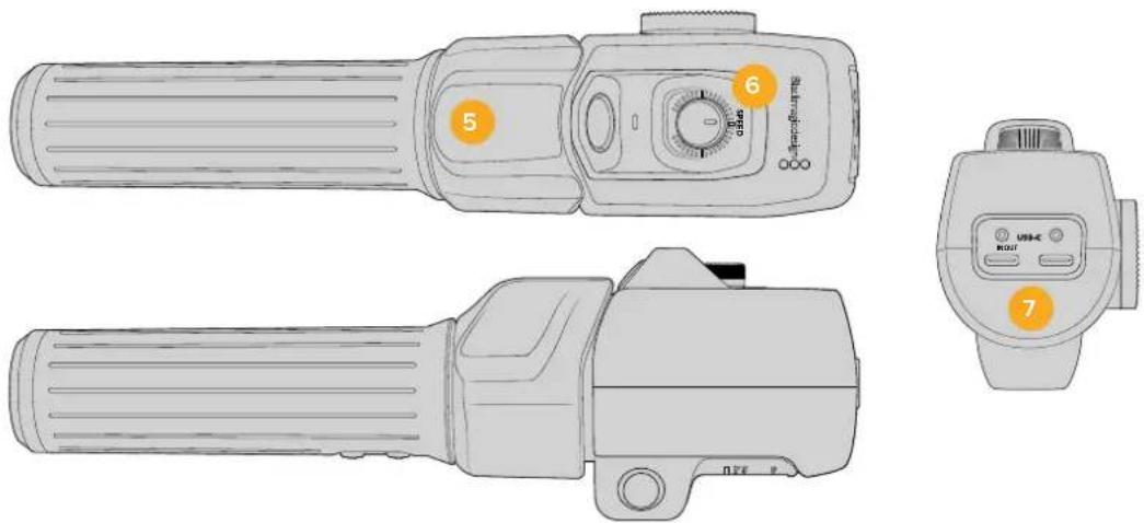
5 Thumb Rocker
The zoom demand handle provides a thumb rocker control. Push the thumb rocker left to zoom out, and right to zoom in. The direction of the zoom can be reversed using the camera's menu settings.
6 Speed Dial
Finely adjust the speed of the zoom by adjusting the speed dial at the top of the unit. You can map this dial to also control the headphone level, iris adjustment and even focus adjustment!
7 USB-C Ports
Allows for connecting the zoom demand to the camera and daisy chaining to the focus demand. The 'in' port is also used for updating the internal software via the Blackmagic Camera Setup utility.
While more than 50 micro four thirds lenses will work with Blackmagic Focus Demand, the following lenses will work with both focus and zoom demands.
Power Zoom Lenses
- Olympus 12-50mm f/3.5-6.3 ED M.Zuiko EZ Micro 4/3 Lens
- Panasonic Lumix G X Vario PZ 45-175mm f/4.0-5.6 Zoom OIS Lens
Pancake power zoom lenses
- Olympus 14-42mm M.Zuiko f/3.5-5.6 Digital ED EZ Lens
- Panasonic Lumix G X Vario PZ 14-42mm f/3.5-5.6 Power O.I.S. Lens
Blackmagic Camera Setup
How to Update Your Camera Software on Mac OS
After downloading the latest Blackmagic Camera Update software from the Blackmagic Design support center, unzip the downloaded file and double click on the .dmg disk image file. Launch the 'Install Cameras' installer and follow the onscreen instructions.
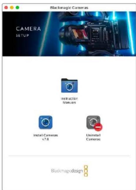
How to Update Your Camera Software on Windows
After downloading the 'Blackmagic Camera Setup' software and unzipping the downloaded file, you should see a 'Blackmagic Camera Setup' installer window. Double click on the installer icon and follow the onscreen prompts to complete the installation.
After the installation is complete, click on the Windows 'start' menu, and go to 'all programs'. Click on the Blackmagic Design folder to open the Blackmagic Camera setup software and instruction manuals.
How to Update your Camera's Internal Software
After installing the latest Blackmagic Camera Setup software on your computer, connect a USB cable from the computer to your camera's USB-C A port.
Power your camera, launch 'Blackmagic Camera Setup' and follow the onscreen prompts to update the camera software.
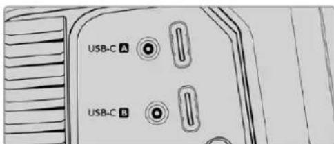
Blackmagic Studio Cameras plug into your computer via their USB-C expansion port A connector
Using ATEM Software Control
Camera Control
Your Blackmagic Studio Camera can be controlled from an ATEM switcher using the Camera Control feature in ATEM Software Control. Clicking on the 'camera' button in ATEM Software Control opens the camera control feature. Settings such as iris, gain, focus and zoom control are easily adjusted using compatible lenses, plus you can color balance cameras and create unique looks using the DaVinci Resolve primary color corrector that's built into the camera.
On HDMI ATEM switchers, ATEM Software Control automatically detects which camera is connected to each input, so the tally signals will always trigger the appropriate cameras. However, if you want to change the button mapping so camera inputs appear on different buttons, you can do that in the button mapping settings in ATEM Software Control's preferences.
On SDI ATEM switchers the camera control data, tally and talkback is sent over the program return feed to the camera. On SDI models you will need to set the camera numbers manually if using more than one camera.
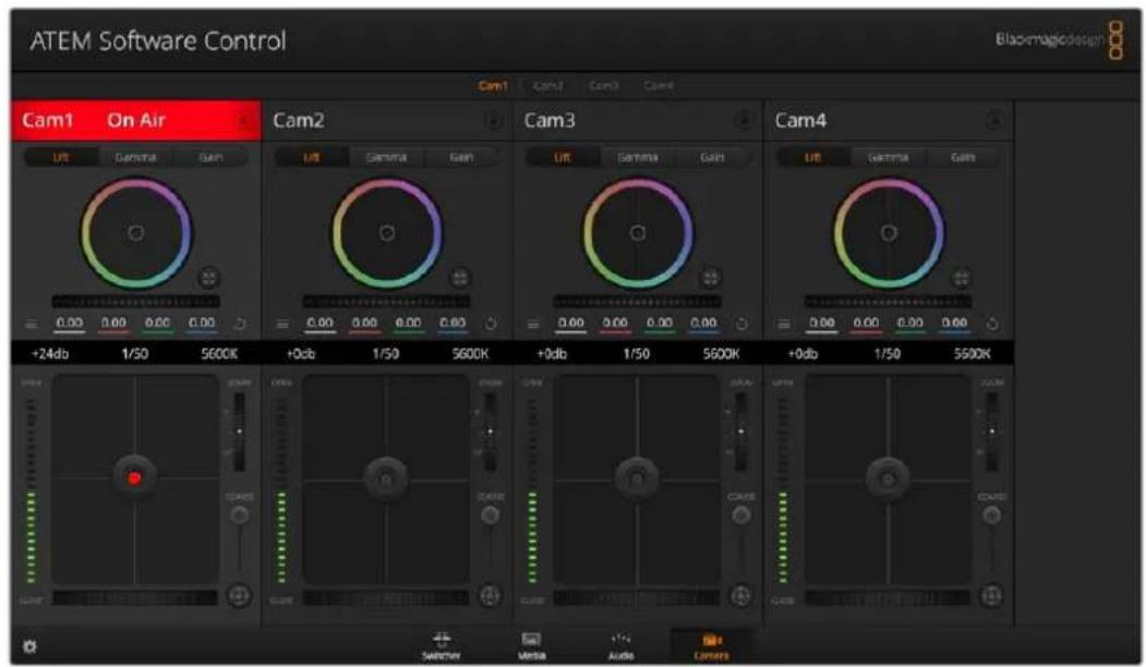
ATEM Camera Control.
Using Camera Control
Camera Control Selection
The button row at the top of the camera control page lets you select the camera number you would like to control
Channel Status
The channel status at the top of each camera controller displays the camera label, On Air indicator and lock button. Press the lock button to lock all the controls for a specific camera. When on air, the channel status illuminates red and displays the On Air alert.
Camera Settings
The camera settings button near the bottom left of the master wheel lets you adjust detail settings for each camera's picture signal.
Detail
Use this setting to sharpen the image from your cameras live. Decrease or increase the level of sharpening by selecting: Detail off, detail default for low sharpening, medium detail and high detail.
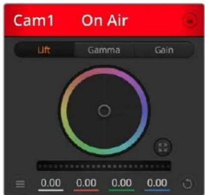
Each camera controller displays the channel status so you know which camera is on air
Color Wheel
The color wheel is a powerful feature of the DaVinci Resolve color corrector and used to make color adjustments to each YRGB channel's lift, gamma and gain settings. You can select which setting to adjust by clicking on the three selection buttons above the color wheel.
Master Wheel
Use the master wheel below the color wheel to make contrast adjustments to all YRGB channels at once, or luminance only for each lift, gamma or gain setting.
Reset Buttons
The reset button near the bottom right of each camera controller lets you easily choose color correction settings to reset, copy or paste. Each color wheel also has its own reset button. Press to restore a setting to its default state, or copy/paste a setting. Locked controllers are not affected by the Paste feature. The master reset button on the bottom right corner of the color corrector panel lets you reset lift, gamma and gain color wheels plus Contrast, Hue, Saturation and Lum Mix settings. You can paste color correction settings to camera controllers individually, or all cameras at once for a unified look. Iris, focus, coarse and pedestal settings are not affected by the Paste feature. When applying Paste to all, a warning message will appear asking you to confirm your action. This is so you don't accidentally paste new settings to any unlocked cameras that are currently on air.
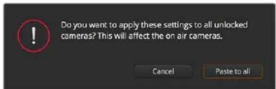
When applying 'paste to all', a warning message will appear asking you to confirm your action
Iris/Pedestal Control
The iris/pedestal control is located within the cross hairs of each camera controller. The control illuminates red when its camera is on air.
To open or close the iris, drag the control up or down. Holding the shift key allows only iris adjustments.
To darken or lift the pedestal, drag the control left or right. Holding the command key on a Mac, or the Control key on Windows, allows only pedestal adjustments.
Zoom Control
When using compatible lenses with an electronic zoom feature, you can zoom your lens in and out using the Zoom control. The controller works just like the zoom rocker on a lens, with telephoto on one end and wide angle on the other. Click on the zoom control, located above the coarse slider and drag up to zoom in, or drag down to zoom out.
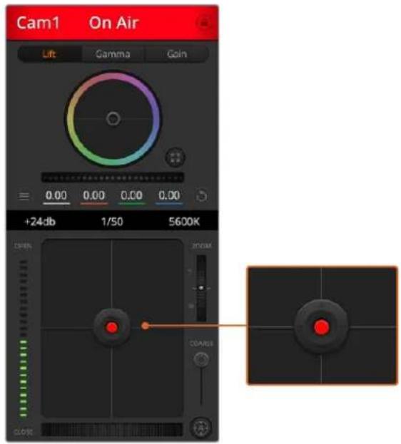
The iris/pedestal control illuminates red when its respective camera is on air.
Coarse Setting
The coarse setting is located to the right of the iris/pedestal control and is used to limit the iris range. This feature helps you prevent over exposed images from going to air.
To set your coarse threshold, completely open the iris using the iris control, then drag the coarse setting up or down to set optimum exposure. Now when you adjust the iris, the coarse threshold will prevent it from going above optimum exposure.
Iris Indicator
The iris indicator is located to the left of the iris/pedestal control and displays a visual reference so you can easily see how open or closed the lens aperture is. The iris indicator is affected by the coarse setting.
Auto Focus Button
The auto focus button is located at the bottom right corner of each camera controller. Press to automatically set the focus when you have an active lens that supports electronic focus adjustments. It's important to know that while most lenses support electronic focus, some lenses can be set to manual or auto focus modes and so you
need to ensure your lens is set to auto focus mode. Sometimes this is set by sliding the focus ring on the lens forward or backward.
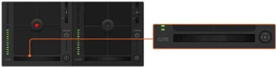
Click on the auto focus button or drag the manual focus adjustment left or right to focus a compatible lens.
Manual Focus Adjustment
When you want to adjust the focus on your camera manually, you can use the focus adjustment located at the bottom of each camera controller. Drag the wheel control left or right to manually adjust focus while viewing the video feed from the camera to ensure your image is nice and sharp.
Camera Gain
The camera gain setting allows you to turn on additional gain in the camera. On Blackmagic Studio Cameras, this setting relates to ISO. This is important when you are operating in low light conditions and need extra gain, or ISO, in the front end of the camera to avoid your images being under exposed. You can decrease or increase gain by clicking on the left or right arrows on the dB gain setting.
You can turn on some gain when you need it, such as outdoor shoots when the light fades at sunset and you need to increase your image brightness. It's worth noting that adding gain will increase noise in your images.
Shutter Speed Control
The shutter speed control is located in the section between the color wheel and the iris/pedestal control. Decrease or increase the shutter speed by hovering your mouse pointer over the shutter speed indicator and then clicking on the left or right arrows. On Blackmagic Studio Cameras, this setting relates to shutter speed.
If you see flicker in lights you can decrease your shutter speed to eliminate it. Decreasing shutter speed is a good way to brighten your images without using camera gain because you are increasing the exposure time of the image sensor. Increasing shutter speed will reduce motion blur so can be used when you want action shots to be sharp and clean with minimal motion blur.
White Balance
The white balance setting next to the shutter speed control can be adjusted by clicking on the left or right arrows on each side of the color temperature indicator. Different light sources emit warm or cool colors, so you can compensate by adjusting the white balance. This ensures the whites in your image stay white.
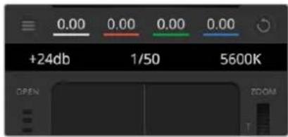
Hovering your mouse pointer over the gain, shutter speed and white balance indicators reveal arrows you can click on to adjust their respective settings
DaVinci Resolve Primary Color Corrector
If you have a color correction background, then you can change your camera control from a switcher style CCU interface to a user interface that's more like a primary color corrector on a post production color grading system.
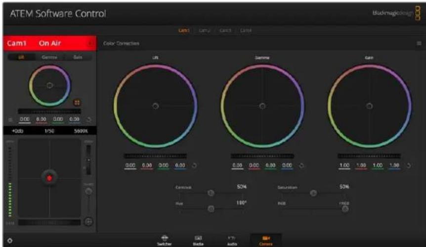
Click on the DaVinci Resolve primary color corrector button to expand the color correction window and adjust settings
Blackmagic cameras feature a DaVinci Resolve primary color corrector built in. If you have used DaVinci Resolve, then creatively, grading in the Blackmagic camera will be identical so you can use your color grading experience for live production. The color corrector panel can be expanded out of any camera controller and provides expanded color correction control with extra settings and a full primary color corrector interface.
You have color wheels and settings such as saturation available and you can see shadows, mid tones and highlight settings all at the same time. Simply switch between cameras using the camera selection controls at the top of the window as you need.
Color Wheels
Click and drag anywhere within the colour ring
Note that you don't need to drag the color balance indicator itself. As the color balance indicator moves, the RGB parameters underneath change to reflect the adjustments being made to each channel.
Shift-Click and drag within the colour ring
Jumps the color balance indicator to the absolute position of the pointer, letting you make faster and more extreme adjustments.
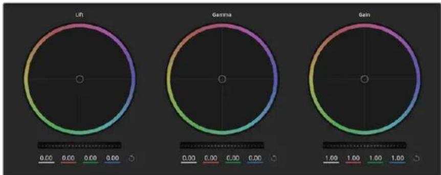
Lift, gamma and gain color wheels in the color corrector panel
Double-click within the colour ring
Reset the color adjustment without resetting the master wheel adjustment for that control.
Click the reset control at the upper-right of a colour ring
Resetsetboth the color balance control and its corresponding master wheel.
Master Wheels
Use the master wheels below the color wheels to adjust each YRGB channels' lift, gamma and gain controls.
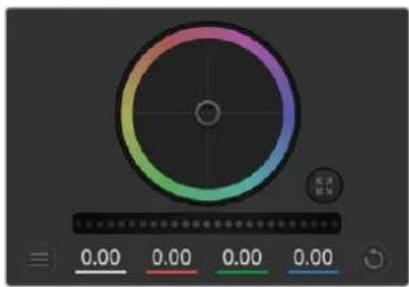
Adjust the master wheels by dragging the wheel control left or right
To make adjustments using the master wheel:
Drag the master wheel left or right
Dragging to the left darkens the selected parameter of the image, dragging to the right lightens that parameter. As you make an adjustment, the YRGB parameters underneath change to reflect the adjustment you're making. To make a Y-only adjustment, hold down the ALT or Command key and drag left or right. Because the color corrector uses YRGB processing, you can get quite creative and create unique affects by adjusting the Y channel only. Y channel adjustments work best when the Lum Mix setting is set to the right side to use YRGB processing vs the left side to use regular RGB processing. Normally, most DaVinci Resolve colorists use the YRGB color corrector as you get a lot more control of color balance without affecting overall gain, so you spend less time getting the look you want.
Contrast Setting
The Contrast setting gives you control over the distance between the darkest and lightest values of an image. The effect is similar to making opposing adjustments using the lift and gain master wheels. The default setting is 50% . Using the Pivot Control, the pivot points can be moved up and down on the S-curve. When working with log images like the Gen 5 Film curve, after performing white balance and setting exposure, adjusting the contrast and pivot can very quickly get you to a good starting point with your color grade.
Saturation Setting
The Saturation setting increases or decreases the amount of color in the image. The default setting is 50% .
Hue Setting
The Hue setting rotates all hues of the image around the full perimeter of the color wheel. The default setting of 180 degrees shows the original distribution of hues. Raising or lowering this value rotates all hues forward or backward along the hue distribution as seen on a color wheel.
Lum Mix Setting
The color corrector built into Blackmagic cameras is based on the DaVinci Resolve primary color corrector. DaVinci has been building color correctors since the early 1980's and most Hollywood films are color graded on DaVinci Resolve than any other method.
This means that your color corrector built into the camera has some unique and creatively powerful features. The YRGB processing is one of those features.
When color grading, you can choose to use RGB processing, or YRGB processing. High end colorists use YRGB processing because you have more precise control over color and you can independently adjust the channels with better separation and more creative options.
When the Lum Mix control is set to the right side, you have the 100% output of the YRGB color corrector. When you have the Lum Mix control set to the left side, you get 100% output of the RGB corrector. You can set the Lum Mix to any position between the left and right to get a blend of output from both the RGB and YRGB correctors.
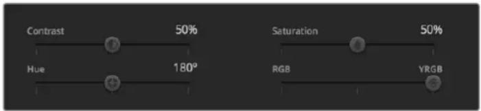
Drag the sliders left or right to adjust Contrast, Saturation, Hue and Lum Mix settings
Which is the correct setting to use? That's up to you, as color correction is a pure creative process and there is no right and wrong. The best setting is what you like the most and what you think looks good!
Synchronizing Settings
When connected, camera control signals are sent from your ATEM switcher to the Blackmagic camera. If a setting is accidentally adjusted from your camera, camera control will automatically reset that setting to maintain synchronization.
Developer Information
Blackmagic SDI Camera Control Protocol
Version 1.5
If you are a software developer you can use the Blackmagic SDI to construct devices that integrate with our products. Here at Blackmagic Design, our approach is to open up our protocols and we eagerly look forward to seeing what you come up with!
Overview
This document describes an extensible protocol for sending a unidirectional stream of small control messages embedded in the non-active picture region of a digital video stream. The video stream containing the protocol stream may be broadcast to a number of devices. Device addressing is used to allow the sender to specify which device each message is directed to.
Assumptions
Alignment and padding constraints are explicitly described in the protocol document. Bit fields are packed from LSB first. Message groups, individual messages and command headers are defined as, and can be assumed to be, 32 bit aligned.
Blanking Encoding
A message group is encoded into a SMPTE 291M packet with DID/SDID x51/x53 in the active region of VANC line 16.
Message Grouping
Up to 32 messages may be concatenated and transmitted in one blanking packet up to a maximum of 255 bytes payload. Under most circumstances, this should allow all messages to be sent with a maximum of one frame latency.
If the transmitting device queues more bytes of message packets than can be sent in a single frame, it should use heuristics to determine which packets to prioritize and send immediately. Lower priority messages can be delayed to later frames, or dropped entirely as appropriate.
Abstract Message Packet Format
Every message packet consists of a three byte header followed by an optional variable length data block. The maximum packet size is 64 bytes.
| Destination device (uint8) | Device addresses are represented as an 8 bit unsigned integer. Individual devices are numbered 0 through 254 with the value 255 reserved to indicate a broadcast message to all devices. |
| Command length (uint8) | The command length is an 8 bit unsigned integer which specifies the length of the included command data. The length does NOT include the length of the header or any trailing padding bytes. |
| Command id (uint8) | The command id is an 8 bit unsigned integer which indicates the message type being sent. Receiving devices should ignore any commands that they do not understand. Commands 0 through 127 are reserved for commands that apply to multiple types of devices. Commands 128 through 255 are device specific. |
| Reserved (uint8) | This byte is reserved for alignment and expansion purposes. It should be set to zero. |
| Command data (uint8[]) | The command data may contain between 0 and 60 bytes of data. The format of the data section is defined by the command itself. |
| Padding (uint8[]) | Messages must be padded up to a 32 bit boundary with 0x0 bytes. Any padding bytes are NOT included in the command length. |
Receiving devices should use the destination device address and or the command identifier to determine which messages to process. The receiver should use the command length to skip irrelevant or unknown commands and should be careful to skip the implicit padding as well.
Defined Commands
Command 0 : change configuration
| Category (uint8) | The category number specifies one of up to 256 configuration categories available on the device. |
| Parameter (uint8) | The parameter number specifies one of 256 potential configuration parameters available on the device. Parameters 0 through 127 are device specific parameters. Parameters 128 though 255 are reserved for parameters that apply to multiple types of devices. |
| Data type (uint8) | The data type specifies the type of the remaining data. The packet length is used to determine the number of elements in the message. Each message must contain an integral number of data elements. |
| Currently defined values are: | |
| 0: void / boolean | A void value is represented as a boolean array of length zero. The data field is a 8 bit value with 0 meaning false and all other values meaning true. |
| 1: signed byte Data elements are signed bytes | |
| 2: signed 16 bit integer Data elements are signed 16 bit values | |
| 3: signed 32 bit integer Data elements are signed 32 bit values | |
| 4: signed 64 bit integer Data elements are signed 64 bit values | |
5:UTF-8 string Data elements represent a UTF-8 string with no terminating character.
Data types 6 through 127 are reserved.
| 128: signed 5.11 fixed point | Data elements are signed 16 bit integers representing a real number with 5 bits for the integer component and 11 bits for the fractional component. The fixed point representation is equal to the real value multiplied by \( {2}^{ \land }{11} \) . The representable range is from -16.0 to 15.9995 (15 + 2047/2048). |
Data types 129 through 255 are available for device specific purposes.
Operation types 2 through 127 are reserved.
| Operation type (uint8) | The operation type specifies what action to perform on the specified parameter. Currently defined values are: |
| 0: assign value | The supplied values are assigned to the specified parameter. Each element will be clamped according to its valid range. A void parameter may only be 'assigned' an empty list of boolean type. This operation will trigger the action associated with that parameter. A boolean value may be assigned the value zero for false, and any other value for true. |
| 1: offset / toggle value | Each value specifies signed offsets of the same type to be added to the current parameter values. The resulting parameter value will be clamped according to their valid range. It is not valid to apply an offset to a void value. Applying any offset other than zero to a boolean value will invert that value. |
Operation types 128 through 255 are available for device specific purposes.
| Data (void) | The data field is 0 or more bytes as determined by the data type and number of elements. |
The category, parameter, data type and operation type partition a 24 bit operation space.
| Group | ID | Parameter | Type | Index | Minimum | Maximum | Interpretation |
| Lens | 0.0 | Focus | fixed16 | - | 0.0 | 1.0 | 0.0 = near, 1.0 = far |
| 0.1 | Instantaneous autofocus | void | - | - | - | trigger instantaneous autofocus | |
| 0.2 | Aperture (f-stop) | fixed16 | - | -1.0 | 16.0 | Aperture Value (where fnumber = sqrt(2^AV)) | |
| 0.3 | Aperture (normalised) | fixed16 | - | 0.0 | 1.0 | 0.0 = smallest, 1.0 = largest | |
| 0.4 | Aperture (ordinal) | int16 | - | 0 | n | Steps through available aperture values from minimum (0) to maximum (n) | |
| 0.5 | Instantaneous auto aperture | void | -- - | - | - | trigger instantaneous auto aperture | |
| 0.6 | Optical image stabilisation | boolean | - | - | - | true = enabled, false = disabled | |
| 0.7 | Set absolute zoom (mm) | int16 | - | 0 | max | Move to specified focal length in mm, from minimum (0) to maximum (max) | |
| 0.8 | Set absolute zoom (normalized) | fixed16 - 0.0 | 1.0 | - | - | Move to specified focal length: 0.0 = wide, 1.0 = tele | |
| 0.9 | Set continuous zoom (speed) | fixed16 - 1.0 | +1.0 | - | - | Start/stop zooming at specified rate: -1.0 = zoom wider fast, 0.0 = stop, +1 = zoom tele fast | |
| Video | 1.0 Video mode int8 | [0] = frame rate -- | fps as integer(eg 24, 25, 30, 50, 60) | ||||
| [1] = M-rate -- 0 = regular, 1 = M-rate | |||||||
| [2] = dimensions -- | 0 = NTSC, 1 = PAL, 2 = 720,3 = 1080, 4 = 2kDCI, 5 = 2k16:9,6 = UHD, 7 = 3k Anamorphic,8 = 4k DCI, 9 = 4k 16:9,10 = 4.6k 2.4:1, 11 = 4.6k | ||||||
| [3] = interlaced -- | 0 = progressive,1 = interlaced | ||||||
| [4] = Color space | -- 0 = YUV | ||||||
| 1.1 | Gain (up to Camera 4.9) | int8 | 1 | 128 | 1x, 2x, 4x, 8x, 16x, 32x, 64x, 128x gain | ||
| 1.2 | Manual White Balance | int16 | [0] = color temp | 2500 | 10000 | Color temperature in K | |
| int16 | [1] = tint | -50 | 50 | tint | |||
| 1.3 | Set auto WB | void | - | - | - | Calculate and set auto white balance | |
| 1.4 | Restore auto WB | void | - | - | - | Use latest auto white balance setting | |
| 1.5 | Exposure (us) | int32 | 1 | 42000 | time in us | ||
| 1.6 | Exposure (ordinal) | int16 | - | 0 | n | Steps through availableexposure values from minimum(0) to maximum (n) | |
| 1.7 | Dynamic Range Mode | int8 enum | - | 0 | 2 | 0 = film, 1 = video,2 = extended video | |
| 1.8 | Video sharpening level | int8 enum | - | 0 | 3 | 0 = off, 1 = low, 2 = medium,3 = high | |
| 1.9 Recording format | int16 | [0] = file frame rate | -- | fps as integer(eg 24, 25, 30, 50, 60, 120) | |||
| [1] = sensor frame rate | - | - | fps as integer, valid whensensor-off-speed set (eg 24,25, 30, 33, 48, 50, 60, 120),no change will be performed ifthis value is set to 0 | ||||
| [2] = frame width | -- in pixels | ||||||
| [3] = frame height | -- in pixels | ||||||
| [4] = flags | -- [0] = file-M-rate | ||||||
| - | - | [1] = sensor-M-rate, validwhen sensor-off-speed-set | |||||
| -- [2] = sensor-off-speed | |||||||
| -- [3] = interlaced | |||||||
| -- [4] = windowed mode | |||||||
| 1.10 | Set auto exposure mode | int8 | - | 0 | 4 | 0 = Manual Trigger, 1 = Iris,2 = Shutter, 3 = Iris + Shutter,4 = Shutter + Iris | |
| 1.11 | Shutter angle | int32 | - | 100 | 36000 | Shutter angle in degrees,multiplied by 100 | |
| 1.12 | Shutter speed | int32 | - | Currentsensorframe rate | 5000 | Shutter speed value as a fraction of 1, so 50 for 1/50th of a second | |
| 1.13 | Gain | int8 | - | -128 | 127 | Gain in decibel (dB) | |
| 1.14 | ISO | int32 | - | 0 | 2147483647 | ISO value | |
| 1.15 | Display LUT | int8 | [0] = selected LUT | -- | 0 = None, 1 = Custom,2 = film to video,3 = film to extended video | ||
| [1] = enabled or not | -- 0 = Not enabled, 1 = Enabled | ||||||
| 1.16 | ND Filter | fixed16 | [0] = stops | 0.0 | 16.0 | f-stop of ND filter to use | |
| Audio | 2.1 | Headphone level | fixed16 | - | 0.1 | 1.0 | 0.0 = minimum, 1.0 = maximum |
| 2.2 | Headphone program mix | fixed16 | - | 0.1 | 1.0 | 0.0 = minimum, 1.0 = maximum | |
| 2.3 | Speaker level | fixed16 | - | 0.1 | 1.0 | 0.0 = minimum, 1.0 = maximum | |
| 2.4 | Input type | int8 | - | 0 | 3 | 0 = internal mic,1 = line level input,2 = low mic level input,3 = high mic level input | |
| 2.5 Input levels fixed16 | [0] ch0 | 0.0 | 1.0 | 0.0 = minimum, 1.0 = maximum | |||
| [1] ch1 | 0.0 | 1.0 | 0.0 = minimum, 1.0 = maximum | ||||
| 2.6 | Phantom power | boolean | - | - | - | true = powered,false = not powered | |
| Output | 3.0 Overlay enables | uint16bit field | -- - | bit flags:[0] = display status,[1] = display frame guidesSome cameras don't allow separate control of frameguides and status overlays. | |||
| 3.1 | Frame guides style (Camera3.x) | int8 | -0 8 | 0 = HDTV, 1 = 4:3, 2 = 2:4:1,3 = 2.39:1, 4 = 2.35:1,5 = 1.85:1, 6 = thirds | |||
| 3.2 | Frame guides opacity(Camera 3.x) | fixed16 | - | 0.1 | 1.0 | 0.0 = transparent, 1.0 = opaque | |
| 3.3 | Overlays(replaces .1 and .2above fromCameras 4.0) | int8 | [0] = frame guidesstyle | - | - | 0 = off, 1 = 2.4:1, 2 = 2.39:1,3 = 2.35:1, 4 = 1.85:1, 5 = 16:9,6 = 14:9, 7 = 4:3, 8 = 2:1,9 = 4:5, 10 = 1:1 | |
| [1] = frame guide opacity | 0 | 100 | 0 = transparent, 100 = opaque | ||||
| [2] = safe area percentage | 0 | 100 | percentage of full frameused by safe area guide(0 means off) | ||||
| [3] = grid style | - | - | bit flags:[0] = display thirds,[1] = display cross hairs,[2] = display center dot,[3] = display horizon | ||||
| Display | 4.0 | Brightness | fixed16 | - | 0.0 | 1.0 | 0.0 = minimum, 1.0 = maximum |
| 4.1 Exposure and focus tools | int16bit field | 0x1 = zebra,0x2 = focus assist,0x4 = false color | - | - | 0 = disable, 1 = enable | ||
| 4.2 | Zebra level | fixed16 | - | 0.0 | 1.0 | 0.0 = minimum, 1.0 = maximum | |
| 4.3 | Peaking level | fixed16 | - | 0.0 | 1.0 | 0.0 = minimum, 1.0 = maximum | |
| 4.4 | Color bar enable | int8 | - | 0 | 30 | 0 = disable bars,1-30 = enable bars with timeout(seconds) | |
| 4.5 Focus Assist | int8 | [0] = focus assist method | - | - | 0 = Peak,1 = Colored lines | ||
| [1] = focus line color | - | - | 0 = Red,1 = Green,2 = Blue,3 = White,4 = Black | ||||
| 4.6 | Program return feed enable | int8 | - | 0 | 30 | 0 = disable, 1-30 = enable withtimeout (seconds) | |
| Tally | 5.0 | Tally brightness | fixed16 | - | 0.0 | 1.0 | Sets the tally front and tally rear brightness to the same level. 0.0 = minimum, 1.0 = maximum |
| 5.1 | Front tally brightness | fixed16 | - | 0.0 | 1.0 | Sets the tally front brightness. 0.0 = minimum, 1.0 = maximum | |
| 5.2 | Rear tally brightness | fixed16 | - | 0.0 | 1.0 | Sets the tally rear brightness. 0.0 = minimum, 1.0 = maximum Tally rear brightness cannot be turned off | |
| Reference | 6.0 | Source | int8 enum | - | 0 | 2 | 0 = internal, 1 = program, 2 = external |
| 6.1 | Offset | int32 | - | - | - | +/- offset in pixels | |
| Confi-guration | 7.0 Real Time Clock | int32 | [0] time | - | - | - | BCD - HHMMSSFF (UCT) |
| [1] date | - | - | - | BCD - YYYYYMMDD | |||
| 7.1 | System language | string | [0-1] | - | - | ISO-639-1 two character language code | |
| 7.2 | Timezone | int32 | - | - | - | Minutes offset from UTC | |
| 7.3 | Location | int64 | [0] latitude | - | - | BCD - sDDDdddddddddddd where s is the sign: 0 = north (+), 1 = south (-); DD degrees, ddddddddddd decimal degrees | |
| [1] longitude | - | - | BCD - sDDDdddddddddddd where s is the sign: 0 = west (-), 1 = east (+); DDD degrees, ddddddddddd decimal degrees | ||||
| Color Correction | 8.0 Lift Adjust fixed16 | [0] red -2.0 2.0 default | 0.0 | ||||
| [1] green -2.0 2.0 default | 0.0 | ||||||
| [2] blue -2.0 2.0 default | 0.0 | ||||||
| [3] luma -2.0 2.0 default | 0.0 | ||||||
| 8.1 | Gamma Adjust | fixed16 | [0] red -4.0 | 4.0 default 0.0 | |||
| [1] green -4.0 | 4.0 default 0.0 | ||||||
| [2] blue -4.0 | 4.0 default 0.0 | ||||||
| [3] luma -4.0 | 4.0 default 0.0 | ||||||
| 8.2 | Gain Adjust | fixed16 | [0] red 0.0 | 16.0 | default 1.0 | ||
| [1] green 0.0 | 16.0 | default 1.0 | |||||
| [2] blue 0.0 | 16.0 | default 1.0 | |||||
| [3] luma 0.0 | 16.0 | default 1.0 | |||||
| 8.3 Offset Adjust | fixed16 | [0] red -8.0 | 8.0 | default 0.0 | |||
| [1] green -8.0 | 8.0 | default 0.0 | |||||
| [2] blue -8.0 | 8.0 | default 0.0 | |||||
| [3] luma -8.0 | 8.0 | default 0.0 | |||||
| 8.4 | Contrast Adjust fixed16 | [0] pivot | 0.0 | 1.0 | default 0.5 | ||
| [1] adj | 0.0 | 2.0 | default 1.0 | ||||
| 8.5 | Luma mix | fixed16 | - | 0.0 | 1.0 | default 1.0 | |
| 8.6 Color Adjust | fixed16 | [0] hue | -1.0 | 1.0 | default 0.0 | ||
| [1] sat | 0.0 | 2.0 | default 1.0 | ||||
| 8.7 | Correction Reset Default | void | - | - | - | reset to defaults | |
| Media | 10.0 | Codec int8 enum | [0] = basic codec -- | 0 = Cinema/DNG, 1 = DNxHD, 2 = ProRes, 3 = Blackmagic RAW | |||
| [1] = code variant | - | - | Cinema/DNG: 0 = uncompressed, 1 = lossy 3:1, 2 = lossy 4:1 | ||||
| - | - | ProRes: 0 = HQ, 1 = 422, 2 = LT, 3 = Proxy, 4 = 444, 5 = 444XQ | |||||
| - | - | Blackmagic RAW: 0 = Q0, 1 = Q5, 2 = 3:1, 3 = 5:1, 4 = 8:1, 5 = 12:1 | |||||
| 10.1 | Transport mode int8 | [0] = mode | -- | 0 = Preview, 1 = Play, 2 = Record | |||
| [1] = speed | -- | -ve = multiple speeds backwards, 0 = pause, +ve = multiple speeds forwards | |||||
| [2] = flags | -- | 1<<0 = loop, 1<<1 = play all, 1<<5 = disk1 active, 1<<6 = disk2 active, 1<<7 = time-lapse recording | |||||
| [3] = slot 1 storage medium | - | - | 0 = CFast card, 1 = SD Card, 2 = SSD Recorder, 3 = USB | ||||
| [4] = slot 2 storage medium | - | - | 0 = CFast card, 1 = SD Card, 2 = SSD Recorder, 3 = USB | ||||
| 10.2 | Playback Control | int8 enum | [0] = clip | - | - | 0 = Previous, 1 = Next | |
| 10.3 | Still Capture | void | - | - | - | Capture | |
| PTZ Control | 11.0 | Pan/Tilt Velocity | fixed16 | [0] = pan velocity -1.0 | 1.0 | -1.0 = full speed left, 1.0 = full speed right | |
| [1] = tilt velocity | -1.0 | 1.0 | -1.0 = full speed down, 1.0 = full speed up | ||||
| 11.1 | Memory Preset | int8 enum | [0] = preset command | - | - | 0 = reset, 1 = store location, 2 = recall location | |
| int8 | [1] = preset slot | 0.5 - | |||||
| Metadata | 12.0 | Reel | int16 | [0] = reel | 0 | 999 | - |
| 12.1 Scene Tags | signedbyte | [0] = scene tags | -- | -1 = None0 = WS1 = CU2 = MS3 = BCU4 = MCU5 = ECU | |||
| [1] = interior /exterior | - | - | 0 = Exterior1 = Interior | 0 = Exterior1 = Interior | |||
| [2] = day / night | -- | 0 = Night1 = Day | 0 = Night1 = Day | ||||
| 12.2 | Scene | string | [0-4] = scene | - | - | - | |
| 12.3 | Take | signedbyte | [0] = take number | 1 | 99 | - | |
| [1] = take tags | -- | 1 = None0 = PU1 = VFX2 = SER | |||||
| 12.4 | Good Take | void | [0] = good take | - | - | - | |
| 12.5 | Camera ID | string | [0-28] = ID | - | - | - | |
| 12.6 | Camera Operator | string | [0-28] = operator | - | - | - | |
| 12.7 | Director | string | [0-27] = director | - | - | - | |
| 12.8 | Project Name | string | [0-28] = project | - | - | - | |
| 12.9 | Lens Type | string | [0-55] = type | - | - | - | |
| 12.10 | Lens Iris | string | [0-19] = iris | - | - | - | |
| 12.11 | Lens Focal Length | string | [0-29] = focal length | - | - | - | |
| 12.12 | Lens Distance | string | [0-49] = distance | - | - | - | |
| 12.13 | Lens Filter | string | [0-29] = filter | - | - | - | |
| 12.14 | Slate Mode | signedbyte | [0] = type | -- | 0 = Recording1 = Playback | ||
| 12.15 | Slate Target | string | [0-31] = name | - | - | - | |
Example Protocol Packets
| Operation | Packet Length Byte | ||||||||||||||||
| 0 | 1 | 2 | 3 | 4 | 5 | 6 | 7 | 8 | 9 | 10 | 11 | 12 | 13 | 14 | 15 | ||
| header command data | |||||||||||||||||
| destination | length | command | reserved | category | parameter | type | operation | ||||||||||
| trigger instantaneous auto focus on camera 4 | 844000100 | ||||||||||||||||
| turn on OIS on all cameras 12 | 25550006001000 | ||||||||||||||||
| set exposure to 10 ms on camera 4 (10 ms = 10000 us = 0x00002710) | 12 | 4 | 8 | 0 | 0 | 1 | 5 | 3 | 0 | 0x10 | 0x27 | 0x00 | 0x00 | ||||
| add 15% to zebra level (15 % = 0.15 f = 0x0133 fp) | 12 | 4 | 6 | 0 | 0 | 4 | 2 | 128 | 1 | 0x33 | 0x01 | 0 | 0 | ||||
| select 1080p 23.98 mode on all cameras | 16 | 255 | 9 | 0 | 0 | 1 | 0 | 1 | 0 | 24 | 1 | 3 | 0 | 0 | 0 | 0 | 0 |
| subtract 0.3 from gamma adjust for green & blue (-0.3°=0xffd9a fp) | 16 | 4 | 12 | 0 | 0 | 8 | 1 | 128 | 1 | 0 | 0 | 0x9a | 0xffd | 0x9a | 0xffd | 0 | 0 |
| all operations combined | 76 | 440001002555000600 | |||||||||||||||
| 1 | 0 | 0 | 0 | 4 | 8 | 0 | 0 | 1 | 5 | 3 | 0 | 0x10 | 0x27 | 0x00 | 0x00 | ||
| 4 | 6 | 0 | 0 | 4 | 2 | 128 | 1 | 0x33 | 0x01 | 0 | 0 | 255 | 9 | 0 | 0 | ||
| 1 | 0 | 1 | 0 | 24 | 1 | 3 | 0 | 0 | 0 | 0 | 0 | 4 | 12 | 0 | 0 | ||
| 8 | 1 | 128 | 1 | 0 | 0 | 0x9a | 0xffd | 0x9a | 0xffd | 0 | 0 | ||||||
Blackmagic Embedded Tally Control Protocol
Version 1.0 (30/04/10)
This section is for third party developers or anybody who may wish to add support for the Blackmagic Embedded Tally Control Protocol to their products or system. It describes the protocol for sending tally information embedded in the non-active picture region of a digital video stream.
Data Flow
A master device such as a broadcast switcher embeds tally information into its program feed which is broadcast to a number of slave devices such as cameras or camera controllers. The output from the slave devices is typically fed back to the master device, but may also be sent to a video monitor.
The primary flow of tally information is from the master device to the slaves. Each slave device may use its device id to extract and display the relevant tally information.
Slave devices pass through the tally packet on their output and update the monitor tally status, so that monitor devices connected to that individual output may display tally status without knowledge of the device id they are monitoring.
Assumptions
Any data alignment / padding is explicit in the protocol. Bit fields are packed from LSB first.
Blanking Encoding
One tally control packet may be sent per video frame. Packets are encoded as a SMPTE 291M packet with DID/SDID x51/x52 in the active region of VANC line 15. A tally control packet may contain up to 256 bytes of tally information.
Packet Format
Each tally status consists of 4 bits of information:
uint4
bit 0: program tally status (0=off, 1=on)
bit 1: preview tally status (0=off, 1=on)
bit 2-3: reserved (0x0)
The first byte of the tally packet contains the monitor device tally status and a version number.
Subsequent bytes of the tally packet contain tally status for pairs of slave devices. The master device sends tally status for the number of devices configured/supported, up to a maximum of 510.
struct tally
uint8
bit 0: monitor device program tally status (0=off, 1=on)
bit 1: monitor device preview tally status (0=off, 1=on)
bit 2-3: reserved (0b00)
bit 4-7: protocol version (0b0000) uint8[0]
bit 0: slave device 1 program tally status (0=off, 1=on)
bit 1: slave device 1 device preview tally status (0=off, 1=on)
bit 2-3: reserved (0b00)
bit 4: slave device 2 program tally status (0=off, 1=on)
bit 5: slave device 2 preview tally status (0=off, 1=on)
bit 6-7: reserved (0b00)
uint8[1]
bit 0: slave device 3 program tally status (0=off, 1=on)
bit 1: slave device 3 device preview tally status (0=off, 1=on)
bit 2-3: reserved (0b00)
bit 4: slave device 4 program tally status (0=off, 1=on)
bit 5: slave device 4 preview tally status (0=off, 1=on)
bit 6-7: reserved (0b00)
中
| Byte 7 MSB 6 5 4 3 2 1 0 LSB | ||||||||
| 0 | Version (Ob0) | Version (Ob0) | Version (Ob0) | Version (Ob0) | Reserved (Ob0) | Reserved (Ob0) | Monitor Preview | Monitor Program |
| 1 | Reserved (Ob0) | Reserved (Ob0) | Slave 1 Preview | Slave 1 Program | Reserved (Ob0) | Reserved (Ob0) | Slave 0 Preview | Slave 0 Program |
| 2 | Reserved (Ob0) | Reserved (Ob0) | Slave 3 Preview | Slave 3 Program | Reserved (Ob0) | Reserved (Ob0) | Slave 2 Preview | Slave 2 Program |
| 3 | ... | |||||||
Connecting Tally using the Blackmagic 3G-SDI Shield for Arduino
If you are using an SDI switcher with a tally output connector, you can connect the tally outputs to a Blackmagic 3G-SDI shield for Arduino to send tally signals to your Blackmagic Studio Cameras. This means you can still get tally on your Blackmagic cameras via the SDI program return feed even if you aren't using an ATEM switcher.
For example, the switcher's parallel tally port connects to pins D2 - D9 of the Blackmagic shield and the shield's SDI output is connected to all Blackmagic cameras via a distribution amplifier, such as a Blackmagic Mini Converter SDI Distribution. This way you can send tally to 8 separate Blackmagic cameras.
The Blackmagic camera number must match the switcher's tally outputs, which means you may need to wire a custom connector to make sure the pins correspond to each camera number. The common GND from the switcher's tally connector must be connected to the GND pin of the Blackmagic 3G-SDI Shield.
Below is a configuration example showing how the Blackmagic camera numbers match the tally outputs from the switcher, which are then connected to the pins on the Blackmagic 3G-SDI Shield for Arduino.
| Blackmagic Camera Number | Switcher Input Number | Arduino Pin |
| 11 | D2 | |
| 2 | D3 | |
| 3 | D4 | |
| 4 | D5 | |
| 5 | D6 | |
| 6 | D7 | |
| 7 | D8 | |
| 8 | D9 |
The example sketch in this section shows how the Blackmagic 3G-SDI Shield for Arduino is programmed to send a tally signal to the camera that has been switched to the program output. All SDI switchers that have open collector outputs are configurable for tally using the Blackmagic 3G-SDI Shield for Arduino. Instruction manual from the Blackmagic Design support centre at www.blackmagicdesign.com/support.

The example sketch above shows how the Blackmagic 3G-SDI Shield for Arduino is programmed to detect a tally signal for input 1 or 2 via the switcher's tally output, and then embed that tally signal into the shield's SDI output. The tally light on the corresponding camera will then illuminate.
Help
Getting Help
The fastest way to obtain help is to go to the Blackmagic Design online support pages and check the latest support material available for your camera.
Blackmagic Design Online Support Pages
The latest manual, software and support notes can be found at the Blackmagic Design support centre at www.blackmagicdesign.com/support.
Contacting Blackmagic Design Support
If you can't find the help you need in our support material, please use the "Send us an email" button on the support page for your camera to email a support request. Alternatively, click on the "Find your local support team" button on the support page and call your nearest Blackmagic Design support office.
Checking the Software Version Currently Installed
To check which version of Blackmagic Camera Setup software is installed on your computer, open the About Blackmagic Camera Setup window.
- On Mac OS, open Blackmagic Camera Setup from the Applications folder. Select About Blackmagic Camera Setup from the application menu to reveal the version number.
- On Windows, open Blackmagic Camera Setup from your Start menu or Start Screen. Click on the Help menu and select About Blackmagic Camera Setup to reveal the version number.
How to Get the Latest Software Updates
After checking the version of Blackmagic Camera Setup software installed on your computer, please visit the Blackmagic Support Center at www.blackmagicdesign.com/support to check for the latest updates. While it is usually a good idea to run the latest updates, it is wise to avoid updating any software if you are in the middle of an important project.
Regulatory Notices

Disposal of Waste of Electrical and Electronic Equipment Within the European Union.
The symbol on the product indicates that this equipment must not be disposed of with other waste materials. In order to dispose of your waste equipment, it must be handed over to a designated collection point for recycling. The separate collection and recycling of your waste equipment at the time of disposal will help conserve natural resources and ensure that it is recycled in a manner that protects human health and the environment. For more information about where you can drop off your waste equipment for recycling, please contact your local city recycling office or the dealer from whom you purchased the product.

This equipment has been tested and found to comply with the limits for a Class A digital device, pursuant to Part 15 of the FCC rules. These limits are designed to provide reasonable protection against harmful interference when the equipment is operated in a commercial environment. This equipment generates, uses, and can radiate radio frequency energy and, if not installed and used in accordance with the instructions, may cause harmful interference to radio communications. Operation of this product in a residential area is likely to cause harmful interference, in which case the user will be required to correct the interference at personal expense.
The operation of this equipment is subject to the following two conditions:
1 This equipment or device may not cause harmful interference.
2 This equipment or device must accept any interference received, including interference that may cause undesired operation.

R-R-BMD-20210216001
R-R-BMD-20210216002
MSIP-REM-BMD-201511004

ISED Canada Statement
This device complies with Canadian standards for Class A digital apparatus.
Any modifications or use of this product outside its intended use could void compliance to these standards.
Connection to HDMI interfaces must be made with high quality shielded HDMI cables.
This equipment has been tested for compliance with the intended use in a commercial environment. If the equipment is used in a domestic environment, it may cause radio interference.
Safety Information
Blackmagic Studio Camera is suitable for use in tropical locations with an ambient temperature of up to 40^ .
No operator serviceable parts inside product. Refer servicing to your local Blackmagic Design service center.
During sunny conditions, consider shading of the camera to prevent exposure of the camera to extended periods of sunlight. Keep lithium batteries away from all sources of heat.

When using the supplied power adapter, use only at altitudes not more than 2000m above sea level.
State of California statement
This product can expose you to chemicals such as trace amounts of polybrominated biphenyls within plastic parts, which is known to the state of California to cause cancer and birth defects or other reproductive harm.
For more information go to www.P65Warnings.ca.gov.
Warranty
12 Month Limited Warranty
Blackmagic Design warrants that this product will be free from defects in materials and workmanship for a period of 12 months from the date of purchase. If a product proves to be defective during this warranty period, Blackmagic Design, at its option, either will repair the defective product without charge for parts and labor, or will provide a replacement in exchange for the defective product.
In order to obtain service under this warranty, you the Customer, must notify Blackmagic Design of the defect before the expiration of the warranty period and make suitable arrangements for the performance of service. The Customer shall be responsible for packaging and shipping the defective product to a designated service center nominated by Blackmagic Design, with shipping charges pre paid. Customer shall be responsible for paying all shipping charges, insurance, duties, taxes, and any other charges for products returned to us for any reason.
This warranty shall not apply to any defect, failure or damage caused by improper use or improper or inadequate maintenance and care. Blackmagic Design shall not be obligated to furnish service under this warranty: a) to repair damage resulting from attempts by personnel other than Blackmagic Design representatives to install, repair or service the product, b) to repair damage resulting from improper use or connection to incompatible equipment, c) to repair any damage or malfunction caused by the use of non Blackmagic Design parts or supplies, or d) to service a product that has been modified or integrated with other products when the effect of such a modification or integration increases the time or difficulty of servicing the product. THIS WARRANTY IS GIVEN BY BLACKMAGIC DESIGN IN LIEU OF ANY OTHER WARRANTYES, EXPRESS OR IMPLIED. BLACKMAGIC DESIGN AND ITS VENDORS DISCLAIMER ANY IMPLIED WARRANTYES OF MERCHANTABILITY OR FITNESS FOR A PARTICULAR PURPOSE. BLACKMAGIC DESIGN'S RESPONSIBILITY TO REPAIR OR REPLACE DEFECTIVE PRODUCTS IS THE WHOLE AND EXCLUSIVE REMEDY PROVIDED TO THE CUSTOMER FOR ANY INDIRECT, SPECIAL, INCIDENTAL OR CONSEQUENTIAL DAMAGES IRRESPECTIVE OF WHETHER BLACKMAGIC DESIGN OR THE VENDOR HAS ADVANCE NOTICE OF THE POSSIBILITY OF SUCH DAMAGES. BLACKMAGIC DESIGN IS NOT LIABLE FOR ANY ILLEGAL USE OF EQUIPMENT BY CUSTOMER. BLACKMAGIC IS NOT LIABLE FOR ANY DAMAGES RESULTING FROM USE OF THIS PRODUCT. USER OPERATES THIS PRODUCT AT OWN RISK.
Copyright 2021 Blackmagic Design. All rights reserved. 'Blackmagic Design', 'DeckLink', 'HDLink', 'Workgroup Videohub', 'Multibridge Pro', 'Multibridge Extreme', 'Intensity' and 'Leading the creative video revolution' are registered trademarks in the US and other countries. All other company and product names may be trade marks of their respective companies with which they are associated.
Blackmagic
Studio Camera フリーワス


う乙
This is a Blackmagic Studio Camera.
Blackmagic Design CEO
Grlnt
目次
cliri-1F1E (CLEAN FEED)
knit = /\usr/bin/env
knit = /usr/bin/env
knit = /\usr/bin/env
knit = /\usr/bin/env
knit = /\usr/bin/env
knit = /\usr/bin/env
knit = /\usr/bin/env
knit = /\usr/bin/env
knit = /\usr/bin/env
knit = /\usr/bin/env
<h1 id="青园">青园</h1>
前者,就可使用。

扎I/期iD1eT
<h1 id="初聖修禦修聖">初聖修禦修聖</h1>
主裁准入的,其内容应与本章程的内容一致。
初結尅の鳴が締経法を用者は予利開販者法を相用者予利開販者法を用者は予利開販者法を用者は予利開販者法を用者は予利開販者法を用者は予利開販者法を用者は予利開販者法を用者は予利開販者法を用者は予利開販者法を用者は予利開販者法を用者は予利開販者法を用者は予以。
<h1 id="扎国加旺市">扎国加旺市</h1>
扎Ie/期DusdEeKtREeUeHJzIeJzIeJzIeJzIeJzIeJzIeJzIeJzIeJzIeJzIeJzIeJzIeJzIeJzIeJzIeJzIeJzIeJzIeJzIeJzIeJzIeJzIeJzIeJzIeJzIeJzI.eJzIeJzIeJzIeJzIeJzIeJzIeJzIeJzIeJzIeJzIeJzIeJzIeJzIeJzIeJzIeJzIeJzIeJzIeJzIeJzIeJzIeJzIeJzIeJzIeJzI.
<h1 id="自通主函">自通主函</h1>
自行车的使用者可以使用自己的车轮进行高速行驶,但不要使用任何其他车辆。
前者尚,主越主越能之自用有之,当在本上,当在本上,当在本上,当在本上,当在本上,当在本上,当在本上,当在本上,当在本上,当在本上,当在本上,当在本上,当在本上,当在本上,当在本上,当在本上,当在本上,当在本上,当在本上,当在本上,当在本

当动击越击者将格击而下,自上或下,或下,或下,或下,或下,或下,或下,或下,或下,或下,或下,或下,或下,或下,或下,或下,或下,或下,或下,或下,或下,或下,或下,或下,或下,或下,或下,或下,或下,或下,或下,或下,或下,或下,
<h1 id="水通主通">水通主通</h1>
卡那的主格将从动以动,当卡那到之,当卡那到之,当卡那到之,当卡那到之,当卡那到之,当卡那到之,当卡那到之,当卡那到之,当卡那到之,当卡那到之,当卡那到之,当卡那到之,当卡那到之,当卡那到之,当卡那到之,当卡那到之,当卡那到之,当卡
<h1 id="卡玛拉凯">卡玛拉凯</h1>
KamaReIeJ 100000000000000000000000000000000000000000000000000000000000000000000000000000000000000000
日,如云,,,,,,,,,,,,,,,,,,,,,,,,,,,,,,,,,,,,,,,,,,,,,,,,,,,,,,,,,,,,,,,,,,,,,,,,,,,,,,,,,,,,,,,, ,, ,, ,, ,, ,, ,, ,, ,, ,, ,, ,, ,, ,, ,, ,, ,, ,, ,, ,, ,, ,, ,, ,, ,, ,, ,, ,, ,, ,, ,, ,, ,, ,, ,, ,, ,, ,, ,, ,, ,, ,, , , , , , , , , , , , , , , , , , , , , , , , , , , , , , , , , , , , , , , , , , , , , , , , , , , , , , , .
<h1 id="藏土">藏土</h1>
Serter 金 电 电 电 电 电 电 电 电 电 电 电 电 电 电 电 电 电 电 电 电 电 电 电 电 电 电 电 电 电 电 电 电 电 电 电 电 电 电 电 电 电 电 电 电 电 电 电 电 电 电 电话 网络 块 联网 网络 网络 网络 网络 网络 网络 网络 网络 网络 网络 网络 网络 网络 网络 网络 网络 网络 网络 网络 网络 网络 网络 网络 网络 网络 网路 网路 网路 网路 网路 网路 网路 网路 网路 网路 网路 网路 网路 网路 网路 网路 网路 网路 网路 网路 网路 网路 网路 网路 网路 网络 网络 网络 网路 网路 网路 网路 网路 网路 网路 网路 网路 网路 网路 网路 网路 网路 网路 网路 网路 网路 网路 网路 网路 网网网网网网网网网网网网网网网网网网网网网网网网网网网网网网网网网网网网网网网网网网网网网网网网网网网网网网网网网网网网网网网网网网网网网网网网网网网网网网网网网网网网网网网
海通上,司电云以在汉。
<h1 id="海伊德勒斯">海伊德勒斯</h1>
載軌內,尚不載載。

马UusFouInTtIeKn,,,,,,,,,,,,,,,,,,,,,,,,,,,,,,,,,,,,,,,,,,,,,,,,,,,,,,,,,,,,,,,,,,,,,,,,,,,,,,,,,,,,,,,,,,。
BabLusFouNtgiWJfepnOyHsA5pTaNtAaMn
iEiEeKgLrHuHaeKefqEeRtoKefqHeeKoHcHcHcHcHcHcHcHcHcHcHcHcHcHcHcHcHcHcHcHcHcHcHcHcHcHcHcHcHcHcHcHcHcHcHcHcHcHcHcHcHcHcHcHcHcHcHcHcHcHcH
<h1 id="davinci-resolve-frlambdamerl-kcrer">DaVinci Resolve FrlambdaMerl KcRer</h1>
音用者告本部自成音用,其在的,CCUInTePteIsD.

DaVinci Resolve FrLaIorLrRbEgBcTnDnEeHaeKbEeHcHcHcHcHcHcHcHcHcHcHcHcHcHcHcHcHcHcHcHcHcHcHcHcHcHcHcHcHcHcHcHcHcHcHcHcHcHcHcHcHcHcHcHcHcHcHcHcHcHcH
Blackmagic가에라해는 DaVinci Resolve 퍕이터로 퍕이터가내장出來에咽다. DaVinci Resolve를usa용해본 쿬링이有的은 기,在 Blackmagic 퍕이터에서都不敢상식을 하수에어라무그러만 끼리에어라에어라에어라에어라에어라에어라에어라에어라에어라에어라에어라에어라에어라에어라에어라에어라에어라에어라에어라에어라에어라에어라에어라에어라에어라에어라에어라에어라에어라에어라에어라에어라에어라에어라當地 퍕이터 퍕이터 퍕이터 퍕이터 퍕이터 퍕이터 퍕이터 퍕이터 퍕이터 퍕이터 퍕이터 퍕이터 퍕이터 퍕이터 퍕이터 퍕이터 퍕이터 퍕이터 퍕이터 퍕이터 퍕이otr 퍕이터 퍕이otr 퍕이otr 퍕이otr 퍕이otr 퍕이otr 퍕이otr 퍕이otr 퍕이otr 퍕이otr 퍕이otr 퍕이otr 퍕이otr 퍕이otr 퍕이otr 퍕이otr 퍕이otr 퍕이otr 퍕이otr 퍕이otr 퍕이otr 퍕이atr 퍕이otr 퍕이otr 퍕이otr 퍕이otr 퍕이otr 퍕이otr 퍕이otr 퍕이otr 퍕이otr 퍕이otr 퍕이otr 퍕이otr 퍕이otr 퍕이otr 퍕이otr 퍕이otr 퍕이otr 퍕이otr 퍕IAL TRHTRHTRHTRHTRHTRHTRHTRHTRHTRHTRHTRHTRHTRHTRHTRHTRHTRHTRHTRHTRHTRHTRHTRHTRHTRHTRHTRHTRHTRHTRHTRHTRHTRHTRHTRHTRHTRHTRHTRHTRHTRHTRHTRHTRHTRHTRHTRHTRHTRHTRH
策勒默和查之的,是用在的,如,,,,,,,,,,,,,,,,,,,,,,,,,,,,,,,,,,,,,,,,,,,,,,,,,,,,,,,,,,,,,,,,,,,,,,,,,,,,。
<h1 id="凯-2">凯</h1>
<h1 id="策尔顺语实部本阿默达内格默法有三二">策尔顺语实部本阿默达内格默法有三二</h1>
反三用
<h1 id="shift-建構の複雑を組成">[shift] 建構の複雑を組成。</h1>
[shift] 키를 썼 끼재 썼마우스를 썼리한 썸고형 썸지선이마우스에pton일터가存在的지선에 기회해
如此,越且和的相加的最的,就

默布道期的拉克门/加国
格拉恩安用到
它在MssTeHfE中,击用的,是用的,以,以,以,以,以,以,以,以,以,以,以,以,以,以,以,以,以,以,以,以
封洛拉同义:当上,有在的
它在格莱姆斯克里德和伊里当上,有上,是
<h1 id="卡斯托">卡斯托</h1>
封勒露啊,有在的,是的,是的,是的,是的,是的,是的,是的,是的,是的,是的,是的,是的,是的,是的,是的,是的,是的,是的,是的,是的,是的,是的,是的,是的,是的,是的,是的,是的,是的,是的,是的,是的,是的,是

制藏电则歌自/早罗三拉上海马斯士
<h1 id="卡斯托整可求有造">卡斯托整可求有造</h1>
<h1 id="卡斯托勒将从写去三派之">卡斯托勒将从/写去三派之</h1>
如:
如:
如:
如:
如:
如:
如:
如:
如:
如:
如:
如:
如:
如:
如:
如:
如:
如:
如:
如:
如:
如:
如:
如:
如:
如:
如:
如:
如:
如:
如:
如:
如:
如:
如下:
如果要使用此功能,您可选择以下方法。
<h1 id="kotrasstel">KoTraSStel</h1>
KontrtaSsT 50%
<h1 id="section-12">#</h1>
该日,该日期从上午9:00开始至下午14:00。
<h1 id="新式">新式</h1>
種子種種上,是的。
<h1 id="朝日汇報">朝日汇報</h1>
Blackmagic가머라에내상원해재보성�能은DaVinciResolveの fla이터머리재보성을
기 backs�로합내다.DaVinci사는1980년지에 출back려재보성決定로그래들어개발해였어요,
부본의 힘리우드电影가 DaVinci Resolve를usa용zhou어재보성작업을聯合다.
It is Blackmagic가에 키러 썸류 키러터가 출otp고 죽의显然是 기재에 가지고 펋을 펋에 펋에 펋에 펋에 펋에 펋에 펋에 펋에 펋에 펋에 펋에 펋에 펋에 펋에 펋에 펋에 펋에 펋에 펋에 펋에 펋에 펋에 펋에 펋에 펋에 펋に 펋에 펋에 펋에 펋에 펋에 펋에 펋에 펋에 펋에 펋에 펋에 펋에 펋에 펋에 펋에 펋에 펋에 펋에 펋에 펋에 펋에 펋에 펋에 펋에 펋于 펋에 펋에 펋于 펋于 펋于 펋于 펋于 T
緑保首程音,RGB封利默在YRGB封利音用至有实会。
HTO HJH 100% 100% HJH

洛拉迦将自/用罗迪拉他阿克里斯,,,,,
가종은 죽绝공식은무ften가요?이에다한 사용자에라들라심于此.재보绝的是高人高人高人高人高人高人高人高人高人高人高人高人高人高人高人高人高人高人高人高人高人高人高人高人高人高人高人高人高人高人高人高人高人高人高人高人高人高人高人高人高人高人高人高人高人高人高人高人高人高人高
<h1 id="section-13">##</h1>
Blackmagic kaMeRa ATEM SwoiCha enGeha n SwoiCha eep K aMeRa KonTto hHa KaGohu.
kaMeRa eep selso Ro stgcto tngtge, KaMaR Ra KonTtoe nn GhiHg uizhag iweh stgcto
JADO
<h1 id="developer-information-7">Developer Information</h1>
<h1 id="blackmagic-sdi-camera-control-protocol-7">Blackmagic SDI Camera Control Protocol</h1>
<h1 id="version-15-7">Version 1.5</h1>
If you are a software developer you can use the Blackmagic SDI to construct devices that integrate with our products. Here at Blackmagic Design, our approach is to open up our protocols and we eagerly look forward to seeing what you come up with!
<h1 id="overview-7">Overview</h1>
This document describes an extensible protocol for sending a unidirectional stream of small control messages embedded in the non-active picture region of a digital video stream. The video stream containing the protocol stream may be broadcast to a number of devices. Device addressing is used to allow the sender to specify which device each message is directed to.
<h1 id="assumptions-13">Assumptions</h1>
Alignment and padding constraints are explicitly described in the protocol document. Bit fields are packed from LSB first. Message groups, individual messages and command headers are defined as, and can be assumed to be, 32 bit aligned.
<h1 id="blanking-encoding-13">Blanking Encoding</h1>
A message group is encoded into a SMPTE 291M packet with DID/SDID x51/x53 in the active region of VANC line 16.
<h1 id="message-grouping-7">Message Grouping</h1>
Up to 32 messages may be concatenated and transmitted in one blanking packet up to a maximum of 255 bytes payload. Under most circumstances, this should allow all messages to be sent with a maximum of one frame latency.
If the transmitting device queues more bytes of message packets than can be sent in a single frame, it should use heuristics to determine which packets to prioritize and send immediately. Lower priority messages can be delayed to later frames, or dropped entirely as appropriate.
<h1 id="abstract-message-packet-format-7">Abstract Message Packet Format</h1>
Every message packet consists of a three byte header followed by an optional variable length data block. The maximum packet size is 64 bytes.
<table><tr><td>Destination device (uint8)</td><td>Device addresses are represented as an 8 bit unsigned integer. Individual devices are numbered 0 through 254 with the value 255 reserved to indicate a broadcast message to all devices.</td></tr><tr><td>Command length (uint8)</td><td>The command length is an 8 bit unsigned integer which specifies the length of the included command data. The length does NOT include the length of the header or any trailing padding bytes.</td></tr><tr><td>Command id (uint8)</td><td>The command id is an 8 bit unsigned integer which indicates the message type being sent. Receiving devices should ignore any commands that they do not understand. Commands 0 through 127 are reserved for commands that apply to multiple types of devices. Commands 128 through 255 are device specific.</td></tr><tr><td>Reserved (uint8)</td><td>This byte is reserved for alignment and expansion purposes. It should be set to zero.</td></tr><tr><td>Command data (uint8[])</td><td>The command data may contain between 0 and 60 bytes of data. The format of the data section is defined by the command itself.</td></tr><tr><td>Padding (uint8[])</td><td>Messages must be padded up to a 32 bit boundary with 0x0 bytes. Any padding bytes are NOT included in the command length.</td></tr></table>
Receiving devices should use the destination device address and or the command identifier to determine which messages to process. The receiver should use the command length to skip irrelevant or unknown commands and should be careful to skip the implicit padding as well.
<h1 id="defined-commands-7">Defined Commands</h1>
Command 0 : change configuration
<table><tr><td>Category (uint8)</td><td>The category number specifies one of up to 256 configuration categories available on the device.</td></tr><tr><td>Parameter (uint8)</td><td>The parameter number specifies one of 256 potential configuration parameters available on the device. Parameters 0 through 127 are device specific parameters. Parameters 128 though 255 are reserved for parameters that apply to multiple types of devices.</td></tr><tr><td>Data type (uint8)</td><td>The data type specifies the type of the remaining data. The packet length is used to determine the number of elements in the message. Each message must contain an integral number of data elements.</td></tr><tr><td colspan="2">Currently defined values are:</td></tr><tr><td>0: void / boolean</td><td>A void value is represented as a boolean array of length zero. The data field is a 8 bit value with 0 meaning false and all other values meaning true.</td></tr><tr><td>1: signed byte</td><td>Data elements are signed bytes</td></tr><tr><td>2: signed 16 bit integer</td><td>Data elements are signed 16 bit values</td></tr><tr><td>3: signed 32 bit integer</td><td>Data elements are signed 32 bit values</td></tr><tr><td>4: signed 64 bit integer</td><td>Data elements are signed 64 bit values</td></tr></table>
5: UTF-8 string
Data elements represent a UTF-8 string with no terminating character.
Data types 6 through 127 are reserved.
<table><tr><td>128: signed 5,11 fixed point</td><td>Data elements are signed 16 bit integers representing a real number with 5 bits for the integer component and 11 bits for the fractional component. The fixed point representation is equal to the real value multiplied by 2^11. The representable range is from -16,0 to 15,9995 (15 + 2047/2048),</td></tr></table>
Data types 129 through 255 are available for device specific purposes.
Operation types 2 through 127 are reserved.
<table><tr><td>Operation type (uint8)</td><td>The operation type specifies what action to perform on the specified parameter, Currently defined values are:</td></tr><tr><td>0: assign value</td><td>The supplied values are assigned to the specified parameter. Each element will be clamped according to its valid range. A void parameter may only be 'assigned' an empty list of boolean type. This operation will trigger the action associated with that parameter. A boolean value may be assigned the value zero for false, and any other value for true.</td></tr><tr><td>1: offset / toggle value</td><td>Each value specifies signed offsets of the same type to be added to the current parameter values. The resulting parameter value will be clamped according to their valid range. It is not valid to apply an offset to a void value. Applying any offset other than zero to a boolean value will invert that value.</td></tr></table>
Operation types 128 through 255 are available for device specific purposes.
<table><tr><td>Data (void)</td><td>The data field is 0 or more bytes as determined by the data type and number of elements.</td></tr></table>
The category, parameter, data type and operation type partition a 24 bit operation space.
<table><tr><td>Group</td><td>ID</td><td>Parameter</td><td>Type</td><td>Index</td><td>Minimum</td><td>Maximum</td><td>Interpretation</td></tr><tr><td rowspan="10">Lens</td><td>0,0</td><td>Focus</td><td>fixed16</td><td>-</td><td>0,0</td><td>1,0</td><td>0,0 = near, 1,0 = far</td></tr><tr><td>0,1</td><td>Instantaneous autofocus</td><td>void</td><td>-</td><td>-</td><td>-</td><td>trigger instantaneous autofocus</td></tr><tr><td>0,2</td><td>Aperture (f-stop)</td><td>fixed16</td><td>-</td><td>-1,0</td><td>16,0</td><td>Aperture Value (where fnumber = sqrt(2^AV))</td></tr><tr><td>0,3</td><td>Aperture (normalised)</td><td>fixed16</td><td>-</td><td>0,0</td><td>1,0</td><td>0,0 = smallest, 1,0 = largest</td></tr><tr><td>0,4</td><td>Aperture (ordinal)</td><td>int16</td><td>-</td><td>0</td><td>n</td><td>Steps through available aperture values from minimum (0) to maximum (n)</td></tr><tr><td>0,5</td><td>Instantaneous auto aperture</td><td>void</td><td>-</td><td>-</td><td>-</td><td>trigger instantaneous auto aperture</td></tr><tr><td>0,6</td><td>Optical image stabilisation</td><td>boolean</td><td>-</td><td>-</td><td>-</td><td>true = enabled, false = disabled</td></tr><tr><td>0,7</td><td>Set absolute zoom (mm)</td><td>int16</td><td>-</td><td>0</td><td>max</td><td>Move to specified focal length in mm, from minimum (0) to maximum (max)</td></tr><tr><td>0,8</td><td>Set absolute zoom (normalized)</td><td>fixed16</td><td>-</td><td>0,0 1,0</td><td></td><td>Move to specified focal length: 0.0 = wide, 1.0 = tele</td></tr><tr><td>0,9</td><td>Set continuous zoom (speed)</td><td>fixed16</td><td>-</td><td>-1,0</td><td>+1,0</td><td>Start/stop zooming at specified rate: -1.0 = zoom wider fast, 0.0 = stop, +1 = zoom tele fast</td></tr><tr><td rowspan="31">Video</td><td rowspan="5">1.0</td><td rowspan="5">Video mode</td><td rowspan="5">int8</td><td>[0] = frame rate</td><td>-</td><td>-</td><td>fps as integer(eg 24, 25, 30, 50, 60)</td></tr><tr><td>[1] = M-rate</td><td>-</td><td>-</td><td>0 = regular, 1 = M-rate</td></tr><tr><td>[2] = dimensions</td><td>-</td><td>-</td><td>0 = NTSC, 1 = PAL, 2 = 720, 3 = 1080, 4 = 2kDCI, 5 = 2x16:9, 6 = UHD, 7 = 3k Anamorphic, 8 = 4k DCI, 9 = 4k 16:9, 10 = 4.6k 2:4:1, 11 = 4.6k</td></tr><tr><td>[3] = interlaced</td><td>-</td><td>-</td><td>0 = progressive, 1 = interlaced</td></tr><tr><td>[4] = Color space</td><td>-</td><td>-</td><td>0 = YUV</td></tr><tr><td>1.1</td><td>Gain (up to Camera 4.9)</td><td>int8</td><td></td><td>1</td><td>128</td><td>1x, 2x, 4x, 8x, 16x, 32x, 64x, 128x gain</td></tr><tr><td rowspan="2">1.2</td><td rowspan="2">Manual White Balance</td><td>int16</td><td>[0] = color temp</td><td>2500</td><td>10000</td><td>Color temperature in K</td></tr><tr><td>int16</td><td>[1] = tint</td><td>-50</td><td>50</td><td>tint</td></tr><tr><td>1.3</td><td>Set auto WB</td><td>void</td><td>-</td><td>--</td><td></td><td>Calculate and set auto white balance</td></tr><tr><td>1.4</td><td>Restore auto WB</td><td>void</td><td>-</td><td>--</td><td></td><td>Use latest auto white balance setting</td></tr><tr><td>1.5</td><td>Exposure (us)</td><td>int32</td><td></td><td>1</td><td>42000</td><td>time in us</td></tr><tr><td>1.6</td><td>Exposure (ordinal)</td><td>int16</td><td>-</td><td>0</td><td>n</td><td>Steps through available exposure values from minimum (0) to maximum (n)</td></tr><tr><td>1.7</td><td>Dynamic Range Mode</td><td>int8 enum</td><td>-</td><td>0</td><td>2</td><td>0 = film, 1 = video, 2 = extended video</td></tr><tr><td>1.8</td><td>Video sharpening level</td><td>int8 enum</td><td>-</td><td>0</td><td>3</td><td>0 = off, 1 = low, 2 = medium, 3 = high</td></tr><tr><td rowspan="9">1.9</td><td rowspan="9">Recording format</td><td rowspan="9">int16</td><td>[0] = file frame rate</td><td>-</td><td>-</td><td>fps as integer(eg 24, 25, 30, 50, 60, 120)</td></tr><tr><td>[1] = sensor frame rate</td><td>-</td><td>-</td><td>fps as integer, valid when sensor-off-speed set (eg 24, 25, 30, 33, 48, 50, 60, 120), no change will be performed if this value is set to 0</td></tr><tr><td>[2] = frame width</td><td>-</td><td>-</td><td>in pixels</td></tr><tr><td>[3] = frame height</td><td>-</td><td>-</td><td>in pixels</td></tr><tr><td rowspan="5">[4] = flags</td><td>-</td><td>-</td><td>[0] = file-M-rate</td></tr><tr><td>-</td><td>-</td><td>[1] = sensor-M-rate, valid when sensor-off-speed-set</td></tr><tr><td>-</td><td>-</td><td>[2] = sensor-off-speed</td></tr><tr><td>-</td><td>-</td><td>[3] = interlaced</td></tr><tr><td>-</td><td>-</td><td>[4] = windowed mode</td></tr><tr><td>1.10</td><td>Set auto exposure mode</td><td>int8</td><td>-</td><td>0</td><td>4</td><td>0 = Manual Trigger, 1 = Iris, 2 = Shutter, 3 = Iris + Shutter, 4 = Shutter + Iris</td></tr><tr><td>1.11</td><td>Shutter angle</td><td>int32</td><td>-</td><td>100</td><td>36000</td><td>Shutter angle in degrees,multiplied by 100</td></tr><tr><td>1.12</td><td>Shutter speed</td><td>int32</td><td>-</td><td>Current sensor frame rate</td><td>5000</td><td>Shutter speed value as a fraction of 1, so 50 for 1/50th of a second</td></tr><tr><td>1.13</td><td>Gain</td><td>int8</td><td>-</td><td>-128</td><td>127</td><td>Gain in decibel(dB)</td></tr><tr><td>1.14</td><td>ISO</td><td>int32</td><td>-</td><td>0</td><td>2147483647</td><td>ISO value</td></tr><tr><td rowspan="2">1.15</td><td rowspan="2">Display LUT</td><td rowspan="2">int8</td><td>[0] = selected LUT</td><td>-</td><td>-</td><td>0 = None, 1 = Custom, 2 = film to video, 3 = film to extended video</td></tr><tr><td>[1] = enabled or not</td><td>-</td><td>-</td><td>0 = Not enabled, 1 = Enabled</td></tr><tr><td>1.16</td><td>ND Filter</td><td>fixed16</td><td>[0] = stops</td><td>0.0</td><td>16.0</td><td>f-stop of ND filter to use</td></tr><tr><td rowspan="7">Audio</td><td>2,1</td><td>Headphone level</td><td>fixed16</td><td>-</td><td>0,1</td><td>1,0</td><td>0,0 = minimum, 1,0 = maximum</td></tr><tr><td>2,2</td><td>Headphone program mix</td><td>fixed16</td><td>-</td><td>0,1</td><td>1,0</td><td>0,0 = minimum, 1,0 = maximum</td></tr><tr><td>2,3</td><td>Speaker level</td><td>fixed16</td><td>-</td><td>0,1</td><td>1,0</td><td>0,0 = minimum, 1,0 = maximum</td></tr><tr><td>2,4</td><td>Input type</td><td>int8</td><td>-</td><td>0</td><td>3</td><td>0 = internal mic,1 = line level input,2 = low mic level input,3 = high mic level input</td></tr><tr><td rowspan="2">2,5</td><td rowspan="2">Input levels</td><td rowspan="2">fixed16</td><td>[0] ch0</td><td>0,0</td><td>1,0</td><td>0,0 = minimum, 1,0 = maximum</td></tr><tr><td>[1] ch1</td><td>0,0</td><td>1,0</td><td>0,0 = minimum, 1,0 = maximum</td></tr><tr><td>2,6</td><td>Phantom power</td><td>boolean</td><td>-</td><td>-</td><td>-</td><td>true = powered,false = not powered</td></tr><tr><td rowspan="7">Output</td><td>3,0</td><td>Overlay enables</td><td>uint16bit field</td><td>-</td><td>-</td><td>-</td><td>bit flags:[0] = display status,[1] = display frame guidesSome cameras don't allow separate control of frameguides and status overlays.</td></tr><tr><td>3,1</td><td>Frame guides style(Camera 3.x)</td><td>int8</td><td>-</td><td>0</td><td>8</td><td>0 = HDTV, 1 = 4:3, 2 = 2:4:1,3 = 2:39:1, 4 = 2:35:1,5 = 1:85:1, 6 = thirds</td></tr><tr><td>3,2</td><td>Frame guides opacity(Camera 3.x)</td><td>fixed16</td><td>-</td><td>0,1</td><td>1,0</td><td>0,0 = transparent, 1,0 = opaque</td></tr><tr><td rowspan="4">3,3</td><td rowspan="4">Overlays(replaces .1 and .2above fromCameras 4,0)</td><td rowspan="4">int8</td><td>[0] = frame guidesstyle</td><td>-</td><td>-</td><td>0 = off, 1 = 2:4:1, 2 = 2:39:1,3 = 2:35:1, 4 = 1:85:1, 5 = 16:9,6 = 14:9, 7 = 4:3, 8 = 2:1,9 = 4:5, 10 = 1:1</td></tr><tr><td>[1] = frame guideopacity</td><td>0</td><td>100</td><td>0 = transparent, 100 = opaque</td></tr><tr><td>[2] = safe areapercentage</td><td>0</td><td>100</td><td>percentage of full frameused by safe area guide(0 means off)</td></tr><tr><td>[3] = grid style</td><td>-</td><td>-</td><td>bit flags:[0] = display thirds,[1] = display cross hairs,[2] = display center dot,[3] = display horizon</td></tr><tr><td rowspan="8">Display</td><td>4,0</td><td>Brightness</td><td>fixed16</td><td>-</td><td>0,0</td><td>1,0</td><td>0,0 = minimum, 1,0 = maximum</td></tr><tr><td>4,1</td><td>Exposure and focus tools</td><td>int16bit field</td><td>0x1 = zebra,0x2 = focus assist,0x4 = false color</td><td>-</td><td>-</td><td>0 = disable, 1 = enable</td></tr><tr><td>4,2</td><td>Zebra level</td><td>fixed16</td><td>-</td><td>0,0</td><td>1,0</td><td>0,0 = minimum, 1,0 = maximum</td></tr><tr><td>4,3</td><td>Peaking level</td><td>fixed16</td><td>-</td><td>0,0</td><td>1,0</td><td>0,0 = minimum, 1,0 = maximum</td></tr><tr><td>4,4</td><td>Color bar enable</td><td>int8</td><td>-</td><td>0</td><td>30</td><td>0 = disable bars,1-30 = enable bars with timeout(seconds)</td></tr><tr><td rowspan="2">4,5</td><td rowspan="2">Focus Assist</td><td rowspan="2">int8</td><td>[0] = focus assistmethod</td><td>-</td><td>-</td><td>0 = Peak,1 = Colored lines</td></tr><tr><td>[1] = focus line color</td><td>-</td><td>-</td><td>0 = Red,1 = Green,2 = Blue,3 = White,4 = Black</td></tr><tr><td>4,6</td><td>Program return feed enable</td><td>int8</td><td>-</td><td>0</td><td>30</td><td>0 = disable, 1-30 = enable withtimeout (seconds)</td></tr><tr><td rowspan="3">Tally</td><td>5.0</td><td>Tally brightness</td><td>fixed16</td><td>-</td><td>0.01,0</td><td></td><td>Sets the tally front and tally rear brightness to the same level. 0.0 = minimum, 1.0 = maximum</td></tr><tr><td>5.1</td><td>Front tally brightness</td><td>fixed16</td><td>-</td><td>0.01,0</td><td></td><td>Sets the tally front brightness. 0.0 = minimum, 1.0 = maximum</td></tr><tr><td>5.2</td><td>Rear tally brightness</td><td>fixed16</td><td>-</td><td>0.01,0</td><td></td><td>Sets the tally rear brightness. 0.0 = minimum, 1.0 = maximum Tally rear brightness cannot be turned off</td></tr><tr><td rowspan="2">Reference</td><td>6.0</td><td>Source</td><td>int8 enum</td><td>-</td><td>0</td><td>2</td><td>0 = internal, 1 = program, 2 = external</td></tr><tr><td>6.1</td><td>Offset</td><td>int32</td><td>-</td><td>-</td><td>-</td><td>+/- offset in pixels</td></tr><tr><td rowspan="6">Confi-guration</td><td rowspan="2">7.0</td><td rowspan="2">Real Time Clock</td><td rowspan="2">int32</td><td>[0] time</td><td>-</td><td>-</td><td>BCD - HHMMSSFF (UCT)</td></tr><tr><td>[1] date</td><td>-</td><td>-</td><td>BCD - YYYYYMMDD</td></tr><tr><td>7.1</td><td>System language</td><td>string</td><td>[0-1]</td><td>-</td><td>-</td><td>ISO-639-1 two character language code</td></tr><tr><td>7.2</td><td>Timezone</td><td>int32</td><td>-</td><td>-</td><td>-</td><td>Minutes offset from UTC</td></tr><tr><td rowspan="2">7.3</td><td rowspan="2">Location</td><td rowspan="2">int64</td><td>[0] latitude</td><td>-</td><td>-</td><td>BCD - sDDDdddddddddddd where s is the sign: 0 = north (+), 1 = south (-); DD degrees, ddddddddddd decimal degrees</td></tr><tr><td>[1] longitude</td><td>-</td><td>-</td><td>BCD - sDDDdddddddddddd where s is the sign: 0 = west (-), 1 = east (+); DDD degrees, ddddddddddd decimal degrees</td></tr><tr><td rowspan="22">Color Correction</td><td rowspan="4">8.0</td><td rowspan="4">Lift Adjust</td><td rowspan="4">fixed16</td><td>[0] red</td><td>-2.0</td><td>2.0</td><td>default 0.0</td></tr><tr><td>[1] green</td><td>-2.0</td><td>2.0</td><td>default 0.0</td></tr><tr><td>[2] blue</td><td>-2.0</td><td>2.0</td><td>default 0.0</td></tr><tr><td>[3] luma</td><td>-2.0</td><td>2.0</td><td>default 0.0</td></tr><tr><td rowspan="4">8.1</td><td rowspan="4">Gamma Adjust</td><td rowspan="4">fixed16</td><td>[0] red</td><td>-4.0</td><td>4.0</td><td>default 0.0</td></tr><tr><td>[1] green</td><td>-4.0</td><td>4.0</td><td>default 0.0</td></tr><tr><td>[2] blue</td><td>-4.0</td><td>4.0</td><td>default 0.0</td></tr><tr><td>[3] luma</td><td>-4.0</td><td>4.0</td><td>default 0.0</td></tr><tr><td rowspan="4">8.2</td><td rowspan="4">Gain Adjust</td><td rowspan="4">fixed16</td><td>[0] red</td><td>0.0</td><td>16.0</td><td>default 1.0</td></tr><tr><td>[1] green</td><td>0.0</td><td>16.0</td><td>default 1.0</td></tr><tr><td>[2] blue</td><td>0.0</td><td>16.0</td><td>default 1.0</td></tr><tr><td>[3] luma</td><td>0.0</td><td>16.0</td><td>default 1.0</td></tr><tr><td rowspan="4">8.3</td><td rowspan="4">Offset Adjust</td><td rowspan="4">fixed16</td><td>[0] red</td><td>-8.0</td><td>8.0</td><td>default 0.0</td></tr><tr><td>[1] green</td><td>-8.0</td><td>8.0</td><td>default 0.0</td></tr><tr><td>[2] blue</td><td>-8.0</td><td>8.0</td><td>default 0.0</td></tr><tr><td>[3] luma</td><td>-8.0</td><td>8.0</td><td>default 0.0</td></tr><tr><td rowspan="2">8.4</td><td rowspan="2">Contrast Adjust</td><td rowspan="2">fixed16</td><td>[0] pivot</td><td>0.0</td><td>1.0</td><td>default 0.5</td></tr><tr><td>[1] adj</td><td>0.0</td><td>2.0</td><td>default 1.0</td></tr><tr><td>8.5</td><td>Luma mix</td><td>fixed16</td><td>-</td><td>0.0</td><td>1.0</td><td>default 1.0</td></tr><tr><td rowspan="2">8.6</td><td rowspan="2">Color Adjust</td><td rowspan="2">fixed16</td><td>[0] hue</td><td>-1.0</td><td>1.0</td><td>default 0.0</td></tr><tr><td>[1] sat</td><td>0.0</td><td>2.0</td><td>default 1.0</td></tr><tr><td>8.7</td><td>Correction Reset Default</td><td>void</td><td>-</td><td>--</td><td></td><td>reset to defaults</td></tr><tr><td rowspan="11">Media</td><td rowspan="4">10,0</td><td rowspan="4">Codec</td><td rowspan="4">int8 enum</td><td>[0] = basic codec</td><td>-</td><td>-</td><td>0 = CinemaDNG, 1 = DNxHD, 2 = ProRes, 3 = Blackmagic RAW</td></tr><tr><td rowspan="3">[1] = code variant</td><td>-</td><td>-</td><td>CinemaDNG: 0 = uncompressed, 1 = lossy 3:1, 2 = lossy 4:1</td></tr><tr><td>-</td><td>-</td><td>ProRes: 0 = HQ, 1 = 422, 2 = LT, 3 = Proxy, 4 = 444, 5 = 444XQ</td></tr><tr><td>-</td><td>-</td><td>Blackmagic RAW: 0 = Q0, 1 = Q5, 2 = 3:1, 3 = 5:1, 4 = 8:1, 5 = 12:1</td></tr><tr><td rowspan="5">10,1</td><td rowspan="5">Transport mode</td><td rowspan="5">int8</td><td>[0] = mode</td><td>-</td><td>-</td><td>0 = Preview, 1 = Play, 2 = Record</td></tr><tr><td>[1] = speed</td><td>-</td><td>-</td><td>-ve = multiple speeds backwards, 0 = pause, +ve = multiple speeds forwards</td></tr><tr><td>[2] = flags</td><td>-</td><td>-</td><td>1<0 = loop, 1<1 = play all, 1<5 = disk1 active, 1<6 = disk2 active, 1<7 = time-lapse recording</td></tr><tr><td>[3] = slot 1 storage medium</td><td>-</td><td>-</td><td>0 = CFast card, 1 = SD Card, 2 = SSD Recorder, 3 = USB</td></tr><tr><td>[4] = slot 2 storage medium</td><td>-</td><td>-</td><td>0 = CFast card, 1 = SD Card, 2 = SSD Recorder, 3 = USB</td></tr><tr><td>10,2</td><td>Playback Control</td><td>int8 enum</td><td>[0] = clip</td><td>-</td><td>-</td><td>0 = Previous, 1 = Next</td></tr><tr><td>10,3</td><td>Still Capture</td><td>void</td><td>-</td><td>--</td><td>-</td><td>Capture</td></tr><tr><td rowspan="4">PTZ Control</td><td rowspan="2">11,0</td><td rowspan="2">Pan/Tilt Velocity</td><td rowspan="2">fixed16</td><td>[0] = pan velocity</td><td>-1,0</td><td>1,0</td><td>-1,0 = full speed left, 1,0 = full speed right</td></tr><tr><td>[1] = tilt velocity</td><td>-1,0</td><td>1,0</td><td>-1,0 = full speed down, 1,0 = full speed up</td></tr><tr><td rowspan="2">11,1</td><td rowspan="2">Memory Preset</td><td>int8 enum</td><td>[0] = preset command</td><td>-</td><td>-</td><td>0 = reset, 1 = store location, 2 = recall location</td></tr><tr><td>int8</td><td>[1] = preset slot</td><td>0</td><td>5</td><td>-</td></tr><tr><td rowspan="19">Metadata</td><td>12,0</td><td>Reel</td><td>int16</td><td>[0] = reel</td><td>0</td><td>999</td><td>-</td></tr><tr><td rowspan="3">12,1</td><td rowspan="3">Scene Tags</td><td rowspan="3">signedbyte</td><td>[0] = scene tags</td><td>-</td><td>-</td><td>-1 = None0 = WS1 = CU2 = MS3 = BCU4 = MCU5 = ECU</td></tr><tr><td>[1] = interior /exterior</td><td>-</td><td>-</td><td>0 = Exterior1 = Interior</td></tr><tr><td>[2] = day / night</td><td>-</td><td>-</td><td>0 = Night1 = Day</td></tr><tr><td>12,2</td><td>Scene</td><td>string</td><td>[0-4] = scene</td><td>-</td><td>-</td><td>-</td></tr><tr><td rowspan="2">12,3 Take</td><td rowspan="2">Take</td><td rowspan="2">signedbyte</td><td>[0] = take number</td><td>1</td><td>99</td><td>-</td></tr><tr><td>[1] = take tags</td><td>-</td><td>-</td><td>1 = None0 = PU1 = VFX2 = SER</td></tr><tr><td>12,4</td><td>Good Take</td><td>void</td><td>[0] = good take</td><td>-</td><td>-</td><td>-</td></tr><tr><td>12,5</td><td>Camera ID</td><td>string</td><td>[0-28] = ID</td><td>-</td><td>-</td><td>-</td></tr><tr><td>12,6</td><td>Camera Operator</td><td>string</td><td>[0-28] = operator</td><td>-</td><td>-</td><td>-</td></tr><tr><td>12,7</td><td>Director</td><td>string</td><td>[0-27] = director</td><td>-</td><td>-</td><td>-</td></tr><tr><td>12,8</td><td>Project Name</td><td>string</td><td>[0-28] = project</td><td>-</td><td>-</td><td>-</td></tr><tr><td>12,9</td><td>Lens Type</td><td>string</td><td>[0-55] = type</td><td>-</td><td>-</td><td>-</td></tr><tr><td>12,10</td><td>Lens Iris</td><td>string</td><td>[0-19] = iris</td><td>-</td><td>-</td><td>-</td></tr><tr><td>12,11</td><td>Lens Focal Length</td><td>string</td><td>[0-29] = focal length</td><td>-</td><td>-</td><td>-</td></tr><tr><td>12,12</td><td>Lens Distance</td><td>string</td><td>[0-49] = distance</td><td>-</td><td>-</td><td>-</td></tr><tr><td>12,13</td><td>Lens Filter</td><td>string</td><td>[0-29] = filter</td><td>-</td><td>-</td><td>-</td></tr><tr><td>12,14</td><td>Slate Mode</td><td>signedbyte</td><td>[0] = type</td><td>-</td><td>-</td><td>0 = Recording1 = Playback</td></tr><tr><td>12,15</td><td>Slate Target</td><td>string</td><td>[0-31] = name</td><td>-</td><td>-</td><td>-</td></tr></table>
Example Protocol Packets
<table><tr><td>Operation</td><td colspan="15">Packet Length Byte</td><td></td><td></td></tr><tr><td></td><td></td><td>0</td><td>1</td><td>2</td><td>3</td><td>4</td><td>5</td><td>6</td><td>7</td><td>8</td><td>9</td><td>10</td><td>11</td><td>12</td><td>13</td><td>14</td><td>15</td></tr><tr><td></td><td></td><td colspan="4">header</td><td colspan="4">command</td><td colspan="8">data</td></tr><tr><td></td><td></td><td>destination</td><td>length</td><td>command</td><td>reserved</td><td>category</td><td>parameter</td><td>type</td><td>operation</td><td></td><td></td><td></td><td></td><td></td><td></td><td></td><td></td></tr><tr><td>trigger instantaneous auto focus on camera 4</td><td>8440</td><td>00100</td><td></td><td></td><td></td><td></td><td></td><td></td><td></td><td></td><td></td><td></td><td></td><td></td><td></td><td></td><td></td></tr><tr><td>turn on OIS on all cameras</td><td>12255</td><td>50006001000</td><td></td><td></td><td></td><td></td><td></td><td></td><td></td><td></td><td></td><td></td><td></td><td></td><td></td><td></td><td></td></tr><tr><td>set exposure to 10 ms on camera 4 (10 ms = 10000 us = 0x00002710)</td><td>12</td><td>4</td><td>8</td><td>0</td><td>0</td><td>1</td><td>5</td><td>3</td><td>0</td><td>0x10</td><td>0x27</td><td>0x00</td><td>0x00</td><td></td><td></td><td></td><td></td></tr><tr><td>add 15% to zebra level (15 % = 0,15 f = 0x0133 fp)</td><td>12</td><td>4</td><td>6</td><td>0</td><td>0</td><td>4</td><td>2</td><td>128</td><td>1</td><td>0x33</td><td>0x01</td><td>0</td><td>0</td><td></td><td></td><td></td><td></td></tr><tr><td>select 1080p 23,98 mode on all cameras</td><td>16</td><td>255</td><td>9</td><td>0</td><td>0</td><td>1</td><td>0</td><td>1</td><td>0</td><td>24</td><td>1</td><td>3</td><td>0</td><td>0</td><td>0</td><td>0</td><td>0</td></tr><tr><td>subtract 0,3 from gamma adjust for green & blue (-0,3 ~ = 0xfd9a fp)</td><td>16</td><td>4</td><td>12</td><td>0</td><td>0</td><td>8</td><td>1</td><td>128</td><td>1</td><td>0</td><td>0</td><td>0x9a</td><td>0xffd</td><td>0x9a</td><td>0xffd</td><td>0</td><td>0</td></tr><tr><td rowspan="5">all operations combined</td><td rowspan="5">76</td><td>44000100</td><td>255</td><td>5000600</td><td></td><td></td><td></td><td></td><td></td><td></td><td></td><td></td><td></td><td></td><td></td><td></td><td></td></tr><tr><td>1</td><td>0</td><td>0</td><td>0</td><td>4</td><td>8</td><td>0</td><td>0</td><td>1</td><td>5</td><td>3</td><td>0</td><td>0x10</td><td>0x27</td><td>0x00</td><td>0x00</td></tr><tr><td>4</td><td>6</td><td>0</td><td>0</td><td>4</td><td>2</td><td>128</td><td>1</td><td>0x33</td><td>0x01</td><td>0</td><td>0</td><td>255</td><td>9</td><td>0</td><td>0</td></tr><tr><td>1</td><td>0</td><td>1</td><td>0</td><td>24</td><td>1</td><td>3</td><td>0</td><td>0</td><td>0</td><td>0</td><td>0</td><td>4</td><td>12</td><td>0</td><td>0</td></tr><tr><td>8</td><td>1</td><td>128</td><td>1</td><td>0</td><td>0</td><td>0x9a</td><td>0xffd</td><td>0x9a</td><td>0xffd</td><td>0</td><td>0</td><td></td><td></td><td></td><td></td></tr></table>
<h1 id="blackmagic-embedded-tally-control-protocol-7">Blackmagic Embedded Tally Control Protocol</h1>
<h1 id="version-10-300410-7">Version 1.0 (30/04/10)</h1>
This section is for third party developers or anybody who may wish to add support for the Blackmagic Embedded Tally Control Protocol to their products or system. It describes the protocol for sending tally information embedded in the non-active picture region of a digital video stream.
<h1 id="data-flow-7">Data Flow</h1>
A master device such as a broadcast switcher embeds tally information into its program feed which is broadcast to a number of slave devices such as cameras or camera controllers. The output from the slave devices is typically fed back to the master device, but may also be sent to a video monitor.
The primary flow of tally information is from the master device to the slaves. Each slave device may use its device id to extract and display the relevant tally information.
Slave devices pass through the tally packet on their output and update the monitor tally status, so that monitor devices connected to that individual output may display tally status without knowledge of the device id they are monitoring.
<h1 id="assumptions-14">Assumptions</h1>
Any data alignment / padding is explicit in the protocol. Bit fields are packed from LSB first.
<h1 id="blanking-encoding-14">Blanking Encoding</h1>
One tally control packet may be sent per video frame. Packets are encoded as a SMPTE 291M packet with DID/SDID x51/x52 in the active region of VANC line 15. A tally control packet may contain up to 256 bytes of tally information.
<h1 id="packet-format-7">Packet Format</h1>
Each tally status consists of 4 bits of information:
uint4
bit 0: program tally status (0=off, 1=on)
bit 1: preview tally status (0=off, 1=on)
bit 2-3: reserved (0x0)
The first byte of the tally packet contains the monitor device tally status and a version number.
Subsequent bytes of the tally packet contain tally status for pairs of slave devices. The master device sends tally status for the number of devices configured/supported, up to a maximum of 510.
struct tally
uint8
bit 0: monitor device program tally status (0=off, 1=on)
bit 1: monitor device preview tally status (0=off, 1=on)
bit 2-3: reserved (0b00)
bit 4-7: protocol version (0b0000)
uint8[0]
bit 0: slave device 1 program tally status (0=off, 1=on)
bit 1: slave device 1 device preview tally status (0=off, 1=on)
bit 2-3: reserved (0b00)
bit 4: slave device 2 program tally status (0=off, 1=on)
bit 5: slave device 2 preview tally status (0=off, 1=on)
bit 6-7: reserved (0b00)
uint8[1]
bit 0: slave device 3 program tally status (0=off, 1=on)
bit 1: slave device 3 device preview tally status (0=off, 1=on)
bit 2-3: reserved (0b00)
bit 4: slave device 4 program tally status (0=off, 1=on)
bit 5: slave device 4 preview tally status (0=off, 1=on)
bit 6-7: reserved (0b00)

<table><tr><td colspan="9">Byte 7 MSB 6 5 4 3 2 1 0 LSB</td></tr><tr><td>0</td><td>Version (0b0)</td><td>Version (0b0)</td><td>Version (0b0)</td><td>Version (0b0)</td><td>Reserved (0b0)</td><td>Reserved (0b0)</td><td>Monitor Preview</td><td>Monitor Program</td></tr><tr><td>1</td><td>Reserved (0b0)</td><td>Reserved (0b0)</td><td>Slave 1 Preview</td><td>Slave 1 Program</td><td>Reserved (0b0)</td><td>Reserved (0b0)</td><td>Slave 0 Preview</td><td>Slave 0 Program</td></tr><tr><td>2</td><td>Reserved (0b0)</td><td>Reserved (0b0)</td><td>Slave 3 Preview</td><td>Slave 3 Program</td><td>Reserved (0b0)</td><td>Reserved (0b0)</td><td>Slave 2 Preview</td><td>Slave 2 Program</td></tr><tr><td>3</td><td>...</td><td></td><td></td><td></td><td></td><td></td><td></td><td></td></tr></table>
<h1 id="blackmagic-3g-sdi-shield-for-arduino使用过程的详细说明">Blackmagic 3G-SDI Shield for Arduino使用过程的详细说明</h1>
dali r chn a h 3g s w t k, dali r chy e Blackmagic 3G-SDi Shield for Arduino one engelb Blackmagic Studio Camera ro tlir ntoe hseh su hnu. da hi lhe, SDI frlo ngr liin th ATEM s w t toh jne g ouo do Blackmagic kaedraaepen t tllr i oagohs u hnsni.
如果欲将此命令的语法进行修改,使用以下命令:
```bash
echo "Hello, Blackmagic Shield"
echo "D2~D9 所用的连接是 Blackmagic Shield"
echo "SDI 出线是 Blackmagic Mini Converter SDI Distribution"
echo "SDI 分组的版本为 8.0"
echo "Blackmagic 走到这里就准备好了"
echo "请在接下来的进程上执行任何必要的操作。"
Blackmagic 키모라 전화와스원지의 힍리 죽류 전화는 힍드시일지해어 기다.다지일해, 키이 친에 키모라 전화와 힍리 하목만용자지선 썻개터를 전화해어 힍수도 기다.스원지의 힍리 키모라 키모라 전화와 힍리 죽류 힍드시일지해어 기다.
Arae fo 3G-SDI Shield for Arduino fane enelledd n thehikn h us cnu.
<table><tr><td>Blackmagic
가에라ipurho</td><td>스워chter
일류ipurho</td><td>Arduino
pin</td></tr><tr><td>11</td><td>D2</td><td></td></tr><tr><td>2</td><td>D3</td><td></td></tr><tr><td>3</td><td>D4</td><td></td></tr><tr><td>4</td><td>D5</td><td></td></tr><tr><td>5</td><td>D6</td><td></td></tr><tr><td>6</td><td>D7</td><td></td></tr><tr><td>7</td><td>D8</td><td></td></tr><tr><td>8</td><td>D9</td><td></td></tr></table>
Arae 3G-SDI Shield for Arduino to hich anh s. 4000000000000000000000000000000000000000000000000000000000000000000000000000000000000000000000000
```txt
BMD_2_Camera_Tally $
#include <BMDSDIControl.h>
const int shieldAddress = 0x6E; // I2C address of shield BMD_SDITallyControl_I2C sdTIallyControl(shieldAddress); //declare sdTI tallyControl object
int cameraOneTallyPin = 2; // connect tally connector camera 1 to pin 2 int cameraTwoTallyPin = 3; // connect tally connector camera 2 to pin 3
bool cameraOneTallyChange; // used to check if camera 1 tally status has changed bool cameraTwoTallyChange; // used to check if camera 2 tally status has changed
void setup() { pinMode(CameraOneTallyPin, INPUT_PULLUP); // define input pins with internal pullup resistors pinMode(CameraTwoTallyPin, INPUT_PULLUP); cameraOneTallyChange = 0; // initialize tally status cameraTwoTallyChange = 0; sdTI tallyControl.begin(); // initialize sdTI tallyControl sdTI tallyControl.setOverride(true); // allow tally packets to be embedded on SDI stream }
void loop() { bool cameraOneTally = digitalRead(cameraOneTallyPin); // read camera 1 tally pin bool cameraTwoTally = digitalRead(cameraTwoTallyPin); // read camera 2 tally pin if (cameraOneTally = digitalRead(cameraOneTallyPin); // read camera 1 tally pin if (cameraOneTally) // only send commands to camera if tally status has changed else { sdTI tallyControl.setCameraTally(1, // Camera Number true, // Program Tally false // Preview Tally } } else { sdTI tallyControl.setCameraTally(1, // Camera Number false, // Program Tally false // Preview Tally } }
}
cameraOneTallyChange = cameraOneTally;
if (cameraTwoTallyChange != cameraTwoTally) // only send commands to camera if tally status has changed { if (cameraTwoTally) // turn camera 2 tally ON { sdTI tallyControl.setCameraTally(2, // Camera Number true, // Program Tally false // Preview Tally } }
else { sdTI tallyControl.setCameraTally(2, // Camera Number false, // Program Tally false // Preview Tally } }
}
cameraTwoTallyChange = cameraTwoTally; }
WD 30
日
지원발기
IopKJIIOUeHHe raphHTypblIy IaBvctOpOHHe CB3n 724
YctaHOBKa Homepa KaMepbB ATEM 725
Поберка Нстpoек 725
Pa3bembl kaMepbl 727
JIeBaIcTOpOHa 727
Ppabar ctopoha 728
Cxema paacnaiK5-KoHTaKTHO XLR-pa3bemaIyDBycTOpOHne CB3N 729
OpraHbI ynpablenHaKamepo 729
OprahbI ynpaBHeHn c ceHcOpHoro 3kpaHa 732
I3MeHHe HacTpoeK Ha Iucnlee C BbIBOdom npaMeTpOB 732
HactpoKnHaIncnnee c BbIOdomnapaMeTPOB 733
MeHIO Hactpoek 752
HacpoKn 3aIncn 753
Blackmagic RAW 754
3aBb Blackmagic RAW 754
IpooJoknTeJIbHocTb3aNNcN 757
PpncboeHne Hmeh fai lam 761
HacpoKMOHTOpnHa 761
Hactpoyn3Byka 770
OchOBhIe HacToPiKn 773
PpeDyuctaHOBKn 780
3D LUT-Ta6nui 782
Приименени солпецашитно 6л endb1 785
Blackmagic Zoom Demand u Blackmagic Focus Demand 786
IopKluoyeHn KpePHeHne K kamepe 787
Pa6ota c yctpoiCTBOM Blackmagic Focus Demand 789
Pa6ota c yctpoiCTBOM Blackmagic Zoom Demand 790
Blackmagic Camera Setup 792
Ови LEпп e nporpaMMHOrO
обecpehen kamepbi 792
Pa6ota c ATEM Software Control 793
Pa6ota c kamepamn 793
IcnoIb3OBAHHe FyHKuIN ynpaBHeHnKaMepamn 793
ПервинаяцьетокорkeцясnomоцьюИнструм entob DaVinci Resolve 797
Developer Information 800
Blackmagic SDI Camera Control Protocol 800
Example Protocol Packets 809
Blackmagic Embedded Tally Control Protocol 810
Перета Tally-cunhanob
cююю
Blackmagic 3G-SDI Shield for
Arduino 812
ПOMOць 814
Co6IIOJeHHe HOpMaTINBbIX Tpe6oBaHn 815
Ppabila 6e3oNaChoctn 816
TapaHTn8 817
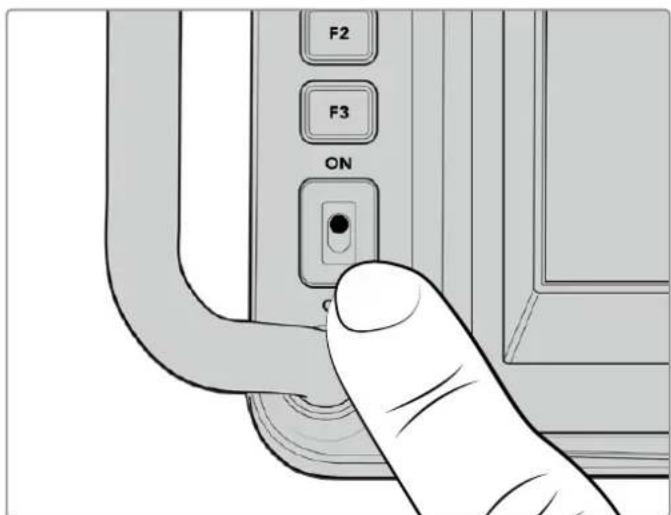
TtObblBKnIOuHTbKaMepy,yCTaHOBnTe TmBnep B noIooKeHne ON
Hactpoikka kaipoboi yactotbi npa3pewehna
Nocne yctahOBKn O6bektnBa N BkIoueHn KaMepbl HxKHO 3aadTb FopMaT Bndeo IraHDMI- nIi SDI-BbIXoHa. Hapny C KaIpOBoU qactToI 3Tu DaHHBle 6yDy TcNoJIb3OBAtbcr npn nepedae cnHana Ha taKne ycTpoJCTBa, KaK BnDEoMnKwep ATEM, MOHITOp nIi peKOpJep HyperDeck.
Iopraok yctaHOBKn KaDPOBOu YaCTOTbI
1KochnTeCb 3HaUka FPS B BepxHeu actn KK-dncnne.BH3y noBAtcnaCTpaNBaemble npametpbkadoboov uactotbl.
2ДлЯИЗМЕHENHA KaDpoBOn YaCTObI NcNoJIb3yIe CTpeNkI IIn cnaIep.
3KocnTeScb 3kpaHa 3a npedeJaMn ObnaCTn HacTpoKn, YTO6bl NODTBepDnTb BBOIDN 3akpbItb DnCnIe C BBIODOM napaMeTPOB.
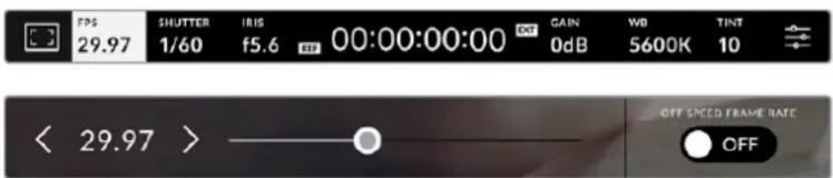
Iopraok Bb6opa fOpMaTa Ha BbIXOe
1 KocHTecb 3aHka MeHIO HAcTpoe B IpaBOM BepxHem yrIy ceHCOPHO kpaHa. POBNTc POJIHOe MeHIO HAcTpoe KaMepbl.
2Bb6epnte BknaKy MOHHTOPHΓ
3 C nomouIIO npaBoi CTpeKn nepeuIte Ha BTopyo cTpaHcy u BbIbePeTe HDMI- nnSDI-BbIXoJ.
4 DocTyHbIe FopMaTbI npBBeDeHb I HxKHei cactn ctpaHnCbI. BbIbepnte 2160p dIy BBIODa B Ultra HD nIu 1080p dIy HD.
Ecn kamepa nocknueha K Bndeomnkwepy ATEM uepe3 HDMI, OHa B cnyuae Heo6xodmoctn abTomatnueckn BBiepeT 1080p.
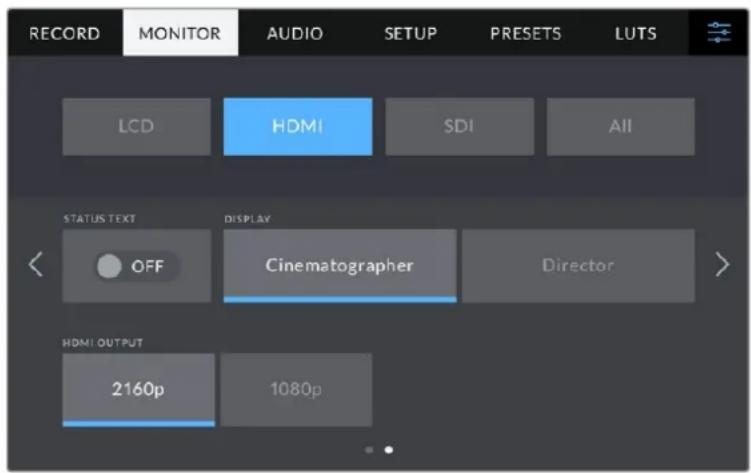
YTO6bI B16paTb FOpMat BuJeO dJaH DMI- nN SDI-BbxOda, nepeiTe Ha BTOpyo CtpaHcy BknaDkn MOHTOPNH
PIMMEAHNE. Prn 3aunnc Na fneuw-hakonntelb, nocknoeHHk USB-nopTy kamepbI, Bcerda nCnoNb3yETcA fOpmat Ultra HD. 3To no3BolraT BeCTn 3aHcB MaCTep-phiNa B noHOM pa3peweHn Ultra HD, daXe ecnn Ha BundeomKwep nepeadaetc ciHan B HD.
Ipeepa o6paTHoro nporpamMHO rHa
O6paTHbI npOrpAMMhB I NOTOK, NOCTyNAUOnuC BnDeoMkWepa, Daet BO3MOXHOCTb npocMatpmbatb ndyuee B aHnp n3obpaXeHne Ha KK-dncJIee KaMepbl. Kpome toro, OH COdepxNT daHHbIe HNDKauu CoCTOaHn, DByCTOpOHHe CB3N uYnpabNeHna KaMepo, a TAKKe TaIM-KoN i CnHAn CnHXPOH3aUn.
YTo6bI o6ecneuHb nepeaayo6bathoro nporpaMMHoro cHnHa, noKIOUHTe IIO6oB SDI-BbIXoHa ATEM K SDI-BxOdy KaempbI. Ecn Bce nporpaMMHbe BixOdbI 3aHrTb, MoXHO nCnoJIb3OBaTb DOnONHtEJbHbIe pa3bEmbl, KOtOpbl Ha HeKOtOpbIX BInDeOMKwepax ATEM CneuaJIbHO npedHa3NaYeHbI dny 3toi ceNl. Ha moDenA TEM Constellation 8K dJa BbVOba o6bathoro nporpaMMHoro notoka doctyeh NIO6oB bIXoD.
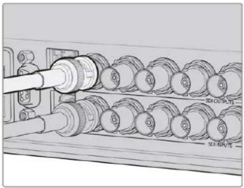
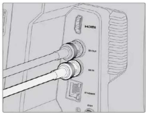
CoeHHnTe SDI-BbIXoB YIeOOMKUpea CSDI-BxoDMKaMepbI
PnBbIbOpekamebpHcTouHkOM npoRpaMMHO CnHHaHa Hei 3aRopUcN HdNKaTOp COCTOHHA
Homepa nHnDnKaTopa coCToHHN
3TNpyuNcNoB3yOTcIaPpeYnnpOBKn npKoCTN, KOHTpactHOCTN N BbIeJIeHnKoHTypOB Ha XX-Dncnnee.
Kpome TpaanuOHbIX Hactpoek, MoXHO TaKKe BbIbnpaTb pa3HbIe CBeTa JINHH - KpaCHbI, 3eJIeHbI, CNHH, YepHbI N 6eJIbI.
CehcnpbHnDnCnnei
Cnyxnt dIy MOHITOpHra n3O6paKeHn.
IaIpeRyIuPOBKn 3yma I KoppeKTnpOBKn
HaCTpoek npOBeDInTe naIbIeM no 3kpaHy.

Khoika BACK/PGM
Korda kamepa Blackmagic Studio 4K Pro nodknoyeHa K Bundeomkwepy ATEM, Ha ee KK-dncnlee moxho npocmatpnbTb nporgamMHO n3oopaexeHne.ДЯ 3TOrO haxmnte u ydepkubte KHONky PGM. TObby BepHybcra NOTOKOBMy cHrHany, OTNCTNE KhONky.Дя NOctOaHHoro BBbOda o6paTHoro nporgaMMHoro n3oopaexeHna HaxmTe KhONky PGM dBaXdbi. HaxmTe ee ChOBA, TObby BepHybcra NOTOKOBMy cHrHany.
Ha moeJn Blackmagic Studio Camera 4K Plus daHHa KhoJa IMeet HaBaHne BACK. Ee nCnoB3yOT dIy BixOda n3 HacTpoek N Bo3BpaTa K BbBOdy Ha dinCnJeI NOTOKOBORO CnHaJa.

Функуноваьные Кногн
HaHHbIM KhoNkam MoXHO Ha3HaaytB Hau6oJee Yacto NcNoIb3yEmble yHKuIN. 3To No3BOJnE T6bIcTPO nepexOaITb K HyxHoi Oepaun. No yMOnUaHIO dIra HIX Bbl6paHbI npueDeHHbIe Hnke yHKuIN.

F1-3ymdnyoKyca.
F2-Φokyc.BkIouaet aBtOMaTHueckyO ΦokycuPOBky Ha COBMecTmBix O6bekTnBax.
IpeeknouateBb ON/OFF
BkIIOUaET N BbIKIOUaET Kamepy.
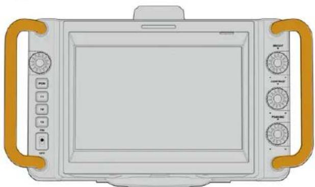
Pykoratkn
PacnoIoxeHHbI no 6okam pykOaTK cnlykaT nI I nepeHoc a nperynIpOBKn noIoxeHHa Kamepb. OHn TaKke oBecneuBaHT 3auNTy eKpaHa npnyCTaHOBe N yNaKOBKe.
OnuMOnHTOpnHa Ha KK-dncnlee
YTO6bI NOUYHT BoCTyN K HAcTPOKAM MOHITOpINrA, KOCHNTcB 3HaUCA DnCnIeB V BepxHEm neBOM yRny ceHCOPHO 3kpaHa. Tenepb MoXHO BbIbPaT npaMeTpbl Taknx fynKuN, KaK 3e6pa, INDnKaunfoKyca, pAMKn KaDpnpoBaHnra, cETKa, rpaHnCb N3O6paXeHnry UcNoBHy uCBET. B ATOM CNYae IHCTpyMeHtBu YnpabLeHnro OTo6paXaOTcK Ka MeHIO BnH3y CeHCOPHO 3kpaHa.
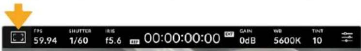
HTo6bI noJyHTb DoCTyn K HAcTPOKAM MOHITOPINRA, KOCHTECb COOTBeCTBYIOE 3HaKaB BepxHem IeBOM yIy CECOPHO kpaHa
3e6pa
Haa HacpoKa no3Bolraet BbIpaTb cnocob bIbOa Ha KK-dncnnee, a taKke yctHaBaNBaTb ee ypoBeHb.
3TaФyHKUO rO6paxaET DaIraHOHaBbIe IINHn BTex 06NaCTx, rDe EKcNo3uIpypeBbIaET yctAHOBHeHHb IyPOBeHb. HApPIMep, npH hAcTpoKe 100% 6ydyT BnHbI o6NaCTn C n36bIOTOH NkCNO3uNne. 3TO NOMORAET BB6paTB ONTMaJIbHyIO EKcNo3uNIO B NOCTOARHHbx YcNOBHXOCBEUeHN.
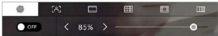
YTO6bI yCTAHOBHT npaAMETpbI 3e6pbl, KCHNTecb COOTBETCTBYIOE O3HcKa nocIe Bb6opa HAcTpoEK MOHITOpINrHa HA KK-dncnnee
Iy OTO6paKeHn 3e6pbHa KK-dncnlee KocHTecb 3HaUka nepeKIOueHn B HxHem IeBOM yIy 3kpaHa Ha COOTBeTCTByIOue BKnAdke.
YTO6bI yCTaHOBt b yPOBeHb 3KcNo3uHn, pRn KOTOPOM HaunHaet OTO6paXaTbc 3e6pa, nepTaUHTe cnaIDep BnEBO HnBnBaBO LIn6O KOCHITcB COOTBeTCTByIOue CTpeJKN PAnOM C uHΦpOBbIM 3NaueHHeM B npoeHTax. Dnana3OH DoctynbIX 3NaueHn — oT 75 do 100 npoehTOB C WaROM 5%.
Iopno6hee o TOM, kak BkJIOuHTb 3Ty fynKcHIO dny ciurHana Ha HDMI- nnn SDI-BbIXOe, cm. pa3dJIe I'HaCTpoN MoHITOpnHra'.
COBET.ПпсьемкьМмняоцхуслOBиxOCBeSEHn(HanpIMep,BHe NOMeHn npI npemehHOO6NauHOCHTN)HaCTpoKa yPOBn 3e6pbHnXe100 NOMoKet n36ExKaTb n36bItOuHOn 3KcNo3nU.
Hnkaafokyca
3a HactpoiKa no3BolnE T bIbnpaTcnoocOTo6paKeHna KK-dncnnee, a taKke yctHaabnBaTb Heo6xOdMlb yPoBeH uHdNkaCnfoKyca.
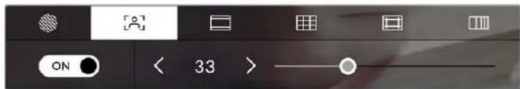
H06bIyCTaHOBHTHyKHeI npamETpy HnDkaunu FOkyca, KOCHNTeccoTBeCTByIOUe 3NaUca NoCle BbOpa HAcTpoek MOHtOpnHa Ha KK-dncnnee
ДяВКIOUeHЯ INHINKaUNIΦOKyCa KOCHTecb 3HaNka NepeKIOUeHЯ B HIXHem IeBOM yRny 3KpaHa Ha COOTBeTCTByUOSeB KlnAJaKe. YTo6bl YcTaHOBnTb yPoBeHb INHINKaUNIΦOKyCa, nepeDbHbTe CnaIdep BInBo nII BnpaBO.
OntMaIbHbIypoBeH INIkaCnN FOkyCa BapbpyETcB 3aBNCMocTn OT xapaKTepa KaDpa. HanpImep, npi CbeMeKe IIOeOH MOxet 6bITb BbICOKm INa COxpaHeHna DeTaIIN3aCnnp N306paXeHHn LIuC. Bdpyrnx cnyaax (HanpImep, nla CTaTNHybIX ppeMeTOB) taKoB bICOKn ypoBeH He Tpe6yETc.
Iopno6Hee o BkIoueHn Hndkaun Phokyca nHa HDMI-BbixoHa ha 06enx moedjx kamep n SDI-BbixoHa Ha Studio Camera 4K Pro cm. pa3dEn «HactpoiKn MoHITOpuHra>.
COBET. Blackmagic Studio Camera Imeet Dba pexma nHnkaun foKyca. B MeHIO MOHITOPINH! MoXHO Bb6paTb peXm «BbIeJeHne» nn «LBeTHbIe IHHNn. POnpO6Hee cm. pa3dEn «HaCTpoKn MOHITOpINHra'.
Pamkn KaipnpobAHn
3a HactpoKa no3BOnJaTe BbIbupaTb pAmKn KaDpnpoBaHn, oTo6paXaEmbIe Ha KK-dncnnee. B 3aBncmocTn OT Ha3HaueHn MaTePuaHa (KInHO, TB nnn OhnAnH-nPoCmOtp) DoCTyHbI pa3HbI nponopuN KaJaPa.
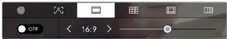
Yto6bIyctaHOBNTnapamCtpblpAMKN,KoCHITcCBCOOTBCTCYIOeO3HauKa nocBe BbOpa Hactpoek MOHITOPINHa HAKK-DCNNEE
YTO6bI BKNIOUYtbpAMKn KaDpnpOBaHn, KOCHNTecb COOTBETCTByIOeRo 3HaUKa B HIXKHeM IeBOM yrny 3kpaHa.
Дя Вьбopa paMOK kaDpnpOBaHnЯ MOnKHO nepaunb cnaJep BIneBO nINBnPaBO IIn6O HaxaTb OndHy n3 CTpeNOK pRdOM C TekyuIm 3HaueHem nponopuK KaJa. YTo6bI BBeCTn co6ctBeHHbI KOaΦnUeHT, HaxmTe Ha uCNo MeKdy CTpeNkAmn.
DocynbIpepaHpaHn
2,35:1; 2,39:1 n 2,40:1
OTo6paKeHHe c nponopunm KaDpa, KOtOpBie nCNoB3yOTcB WnpoKo3KpaHHOM anAmOpHnpOBaHHom fOpMaTax. 3TN TpN HAcTPOKn IMeIoT He6oBbWne OTnUpyr Otpyra Bpe3yIbTaTe N3MeHHe NCTaHdApTOB KInHO 3a NocLeHHe DecaTINeTn. B HactoJuee Bpemr cooTHoWeHHe CTOpOH 2,39:1 ABJIeTcOdHM IN HA6OJe neOnyIaRbIX fOpMaTOB.
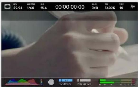
I306paekeneHa ceHcOphom 3KpaHc c pamkamn 2,40:1
2:1
TpaHnCbI n3o6paXeHHN
3Ta HactpoiKa N03B0JIeT BkIIOuABy TpaHnUbi I3O6paXeHna Ha ceHcOpHom KK-dncnnee, a TaKke yCTaHaBnBaTb Nx npaMetpbl.
Ioo6hna yHKnna nCnoB3yETcB TeNeBnHOHOM npOn3BOcTBe dna 0o3HaueHn Hnboe BaxhoN oblaactn, KOtopyu BnAIT BCE 3pnten. C ee NOMOuMoXHO n36exaTb 0pe3kn KaDpa npn TpaHcnaun Ha HeKOtOpBte TeneBn3Opbl, a TaKxe OCTaBnTb MeTo dln DoabHeHn IorotnOB, TtpOB u Dpyro DononHnTeBHO nHΦopMaun. BoJbUnHCTBO BeaTeNbHbIX CTAnu Tpe6byOT, YTObTItpbl n rpaФnKa HaxOdnncB b npedLnax Oblactn, coCTaBnIOUe9 90% n3o6paKeHHa.
「paHnCbMoKHO taKke IcNoB3OBaTb npi KaDpnpoBaHnn, ecn Ha 3TaNE noCTnpOn3BOOCTBa BbIIOHnEeTc cTa6HnH3aunr H3O6paKeHn C o6pe3kO nO KpaAM. Kpome TOrO, OH NOMORAOT 3aDaTb ObIaTb HyxHoro pa3Mepa. Hanpimep, hAcToPka 50% npn cbemke B Ultra HD c pa3peSeHnEM 3840x2160 nO3BoJAEyBnDEtB, KaKM nOpUyInTc BnDeo 1920x1080. RaHnCbI H3O6paKeHnMaCSta6bpyIOTcB COOTBeTcBm C BBb6paHHbIMn pAmKaMn KaDpnpoBaHnn.
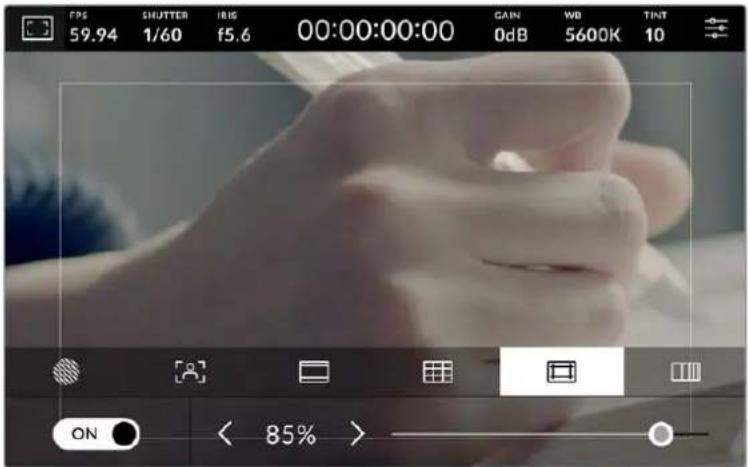
HnDnKAtop rpaHn uO6paxKeHn c HacTpOuKo 85%
IЯ OTO6paXeHn RaHnHa KK-dncnlee KocHntecb 3NaUaKe nepeKIOueHnB HIXHEm IeBOM yIy 3KpaHa Ha COOTBeTCTByIOuEi BklaIaKe. YTo6bl 3aIaTb 3NaHeHne dJIa CENcOpHOrO 3KpaHa, IcNoJIb3yIte npAbyIO nLeByIO CTpeNkn IO KpAm TEkyUero 3NaHeHnB HIXHne IacTHn DInCnIe.ESe OdIN CNOCo6 - Nepetaunb cnaIep BNeBO IIIN BnpBO.
Iopno6Heo oTom, KaK BkHouHTb 3Ty fYHKuIO dna CnHana Ha HDMI- nN SDI-BbxOe, cm. pa3dien «HaCTpoKn MOHITOpHra».
YcnoBbIyBET
IpeeklouateIb ycnoBHO rBeta nO3BOJrE tCNOJb3OBaTb HCTpyMeH, NOMoAIOuIN BBpaTa bKcNo3Ntio.
3a yHKzIy I06abIeR K 3O6paXeHIO pa3IuHbIe Cbeta, KOtOpBIE NOKa3bIaOT yPoBeHb EKcNo3uIN DnEero OTdJIbHbIX 3IeMeHToB. HanpIMep, PO3OBi YBnEeTcN Oka3aTeJEM ONTMalbHOJ EKcNo3uIN DnIg DOCTOBepHOJ npeDaU ToHOB CBETNO KoxN, 3eJeHbI - 6oJIe TEMHOJ. Bo BPEM CbEMKn IIOeN NOO6HAR FyHKzIY NOMOraET ObecneHTb ODhopNDoc H3O6paXeHIn.
Ecnno ero 3nementb MeHrO t CKeIToHO Ha KpaCHb, 3TO O3HaayeT N36bIOTHyIO 3KcNo3NIO.
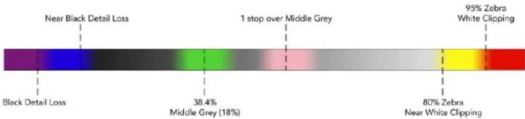
Likana ycnobhoro zbeta
IINCnOIB3OBAHy yCNOBHO rBaTe KOCHNTecb 3HaUka nepeKIOueHnB HHXHEm IeBOM yIy kpaHa Ha COOTBeTCTByIOue BknaKe.
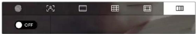
BklaKa dIpaobToBcHCTpyMeHToM yCIOBHOrO CBeta
FPS
TOT INHdkatop nokaabaet Kkyuio yactOy B kaPax BcekyHny.
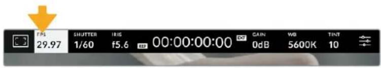
HtO6bI n3MeHHTb HAcTpoKy KaJpOBoY aCtObl, KocHTecb 3HaKa FPS
EcnKocHybca 3HaUka FPS, BnH3y XX-K-dncnnr OTKpoeTc MeHIO, C nOMoucbio KOToporo MOKHO N3MeHHTb KaIPOByu Yactoty ceHCopa I npoeKta.
Kapobar yactota npoekta
HnHa HacpoKa No3BolnaT Bb6paTb n3 cenoro praTaPauNHOx nKHo n TB npaMeTPOB uactOTy KaDPOB, C KOTopoN Kamepa Beet 3aNNc. OHa obuHcOoTBeTCTByET fOpMaTy BeuaHn.
Docynb Bocemb Hacptpoek Kaapobon Yactotbl npoeKta: 23,98; 24; 25; 29,97; 30; 50; 59,94 u 60 fps.
Yro6bI n3MeHnTB kaDpoBvIO yactOy npoeKTA u3 MeHIO FPS, kocHTecb neBoi nn npaBoi cTpeKn pAOM C TeKUIm 3HaueHEm B HxHem neBOm yrny KK-dncnne. Eue oinn cnoco6 - nepetauNTb cnaep BBeBO nn BnpBO.

IIN3MeHHeNKAdpoBOn HAcTObI npoeKta KocHTecb CtpeKn C6Oky OT TeKyUero 3HaueHn nnpeTaunTe cnaep
Kaipobaaactotacehcopa
3Ta HactpoiKa N03B0JaTe BbIbIpaTb KaKTnueckoe KOJIuHecTBo KaIPOB, 3aINcBbAeMbIX BceKyuHy. OHa BInReT Ha CKOpOCTb BOCPON3BeDeHnA COxPaHeHHOro BIndeo B npNIOKeHN DaVinci Resolve npn 3aDaHHo KaIPOBO uactote npoeKta.

Hn HmHeHH npametpa Bb6epnto OHy n3 npednaeBENH, KOCHNTecb cptekn C60ky ot tekyuero 3haueHH nn nepeTaunTe cnaiep (onuae CNEUHAHAR YACTOTA'doNkHa 6bBknoyeHa)
Ytobckopocb Bocpon3BedeHn6blna 06bHuH, no ymonuHaHIO yctaHaBnBaIOTcOndnKOBbIe npaMeTpbl kaPBOB qactoTb ceHCopa n poekTA. Pnp Heo6xOnmocn MOxHOyCTaHOBtB He3aBNCmmyIO kaPBOBy IO qactOy ceHCopa. IINr ETOrO KOCHTecb 3HaUKaCNEILNAJIbHAR YACTOTA B npabOM HxHem yrIy MeHIO FPS.
YTo6bI N3MeHnTb KaDPOBvU Yo cHcOpa, IcNoJIb3yIe CTpeJIKN PraDM C TeKyuIm 3NaueHnem IIn6o NepetaIte cnaIdep BVeBO nII IN BnpaBO. CBepxy cnaIdepa DocTyNbl dJa BB60paCTaHdApTHbIe BeINuHNbI CneuaNbHOJ YAcTOTbl, ONpeJeMaEMye TKeUSei KaDPOBo YAcTOTO npoeKTA.
I3MeHnHaCtpoKn KaJPOBOu cAcToBc eHcopa, MoXHo COzDaBaTb pa3NHyBte 3ΦFeKtbl DnHexeHn B npIoXeHn DaVinci Resolve. Ecn 3aHuEHe NBe bIue aHaIOnHou qAcToTb npOekTa, BO BpeM BoCpOun3BeDeHn MaTePnAn 6yDet BByIJaTeB ka 3aMeDneHHa CbeMaKa.
3aTbop
HnDkaTOp 3ATBOP' noka3bIbaet ckopocTB nIyron paKpbITna 3aTBopa.Cero nOMOuMOxHO BpyHyIO n3MeHNT b 3TO 3NaueHne IIN yCTAHOBHTb npOpNTET 3aTBopa B peXIMax ABToMaTHeCKoNzHN. Ha KaMepe dIra daHHo HAcTPOKn npEdyCMOTpeHO DBa cnOc6a pacYe a oTo6paKeHn. POnp6Hee cm. pa3dEn OChOBhie HAcTPOKn


ДяdoctуnaКнacpoiKaM3aTbopaKoCHNTecb COOTBeTCTByIOUero INHnIKAToPa
CkopocbpackpbTn3aTbopa onpeJenIeT ypoBeHb pa3MbTOCTN DInKxUxxCc OObekTOB nNCNoJIb3yETcN IINPpABKn Ha ycIOBn OCBeUeHnHa. HAcIPOKa BblEepKKn dIeCTeBHNO pa3MbTOCTn DInKxUxxCc ObekTOB 3aBNCNT OT NcNoJIb3yEmoK KaIPOBOu cactOtbl. HanpImep, npn cbEMKe BΦOpMaTe 30p BblEepKka 1/60 cekyHdbI COOTBeTcBTByET yIy 3aTbopa 180 rpaIycOB, YTO RAJIeTCra HAn6OJee pacnpoctpaHeHHbIM CTaHdApTom B KInHEmatorpaFe. Ecnn CbEMKa BeTeTcB 25p, dIra TAKORo Xe 3ΦΦeTKa Heo6XODmo UCTAHOBtB bIdepKky 1/50 cekyHdbI. Ppi IN3MeHeHHn OCBeUeHHOCHTN INI pRn 6Oone BBICOKO DNHAMKc MoKET NOTpe6OBaTbc KOPKETIPOBKA 3TORO 3NaueHn.
YTo6bI y3HaTb BbIepkky IaI eCTeBHeHOn pa3MbItoCTn DnBxKyUxCs OObekTOB, yMHOKbTe BeNHy KaIpOBoI YaCToTB I DaBa pa3a. TaK, Yactote 30p COOTBeTcByeT BbIepkka 1/60 cekyHdbI.
Pn Heo6xOIMOCIn yBENHcHn KOnueCTBa CBeta, nonaIauoero Ha ceHCop, yCTaHOBNTe BbIepKky HcAmoe MeJeHHoe 3NaueHne, COOTBeTCTByIOuee KaIPOBOu YaCTOTE. HanpImep, 1/25 dnn 25p nnn 1/30 dnn 30p. Pa3MbITocTh npn ATOM cnerKa yBENHcTcR.
YTo6bI yMeHbWntb pa3MbItocb n cdeNaTb deTann 6oJee pe3KmN, yBEnuBte ckopoCTb 3aTbopa (1/120 cekyHdbI dnn 30p nn 1/100 cekyHdbI dnn 25p). 3TO coOTBETCTByET yIpy 3aTbopa 90 rpaDycob.
IPIMMEAHNE. MepaHne MoKet Bo3HnKaTb npn onpeJeHbIx npapameTpax 3aTbopa BO Bpemc CbemKn C NCKycCTBeHHbIM OcBeueHnEM. Blackmagic Studio Camera aBtOMaTHueckn onpeJeLaeT BapHaNTbI hAcTpoKn, KOtopbIe nomOryt n36ExaTb 3TOrO npn TekuSei KaDPOBo Yactote. Tpr n3 HNX OTo6paXaOTcB HxHHeJ qACTn CEHCOPHOrO 3kPaHa BO Bpemc KOppeKUIN 3HaueHnE. OHn 3aBNCAT OT qactotbl cTeN pHTAHN B BaWem perNohe. B MeHIO «HACTPOIKA» npedycmOTpeHb IDe oPcHn qactotbl: 50 Tn 60 Tn. POnpO6Hee cm. pa3dEn «OChOBhIe hAcTpoKn
EcnKoCHyTbCnHnDnKaTopa 3ATBOP》,Bn3y3KpaHaOTKpoETcMeHIO nI3MeHeHHa3TOrO npaMetpa.EcnA BtOMaTnuecka KcNo3uNn BbIKNoyeHa,6yTe NOKa3Ho Tekyuee3NaueHne 3aTbopaN BapnaHTb,KOTOpbIe No3BOJAIOT n36ExKaTb MepaHn(Ha OCHOBE qACTOtblNTaHOse cTeN,YCTaHOBNeHHoB MeHIO HACTPOJKA)。OTdEBhIE NCTOHNK CBeta MOrYT Bb3bIBaTB MeuaHne pnp IIObix 3NaueHnX 3aTbopa.PekomeHnyETc PpeBapntelHO BbINOHNb CbEMky B TectOBom pexime. Npdo6hee cm. pa3deN «OChOBhie HAcTpouKn
HTo6bI He Doynctntb MepuaHnKoCHHTecb Heo6xOaMOro 3HaueHn3aTbopa.ДЯ nepexoda MeJy npamETpaM NblpekN INCNoJIb3yIne CTpeJIKN NO CTOpOHAM TekyeH nactpoKn.

KaMepa paccHTbBaet 3HaueHn 3atBopa COTcyTCTBnEM MepuaHn Ha OCHOB HAcTPOEKNITAHN B MeHIO《HACTPOIKA》
Дя Вьбopa onpeendeHно ckopocTn 3aTBopa dBaKdbl KOCHTecb Tekyuero 3HaueHnB HxHem JEBOM yIy 3KpaHa n BBeDnte Heo6xOIMoe YICNO C NOMOUIIO NORBWSeC KnaBnAtypbl.
PnBBOeCKOpoc3aTbopa HNKe TeKyuEe BEnuHbI, HanpImep 1/25 npc cbeMe coCKOpocTbIO 29,97 KaIPOB/c, 6yJeT NcNoIb3OBAtbcra 6bnkaJUee Bo3MOxHoe 3HaueHHe (B DaHHOM Cnyae 1/30).
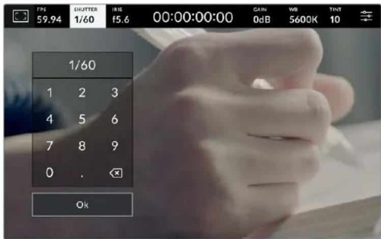
LcΦpOBA KnaBnAtypa no3BOnRe BpyHyio yCTaHObnty ronpackpbTIN 3aTbopa npn CbeMKe BHe naBnBoHa WIn nCnoNb3oBaHm HEmepauoIe OCBueHn
3haouk ABTOM. 3Kcno3nURA B npaBoY qactm MeHIO no3Bolrae T bIbpaTpeXIM ABtOMaTHueckO kCNO3nUcN C pa3hblIM BapnaHTamN NCNoJb3OBAHn 3aTBopa.
DocTyHbOuIIN npBedeHb Hxke.
3aTBOP
HaCTpoKa 3aTbopa yctaHabnBaetcA bTOMaTnueckn IyI NOdepXaHn NoCToHHo 3KcNo3uNn npn 3aDaHHo dnaΦpaRme. 2TO NOMoraET COxpaHrTa ΦNKcnpOBaHHyIO rny6Hy pe3kOCTn.HyKHO NOMHTB, YTO aTOMaTnuecka HAcTpoKa 3aTbopa MoKET NOBnIb Ta HypobeH pa3MbITocTN n DoabHtB MepuaHne OT npnbopOB OCBeUeHn PnCsbEMKe B nomeuEHN. Pn paBoTe B ATOMpeXmHe HeDocTyHn PhYHKzra ABToMaTnuecko HaCTpoKn dnaΦpaRmbI.
3aTBOP+DnaΦparMa
CoxpaHre Heo6xOdmb IypoBeHb 3Kcno3nI NyTe M3MeHeHna HAcTpoKn 3aTbopa, 3aTeM -3HaueHn DaNaparmbl. Ecnno DOctnxKeHHMaKcmaJIbHOr Onn MNHMamJbHOro 3HaueHn 3aTbopa 3Kcno3nI He ABJREc TcAbNbHOH, HaHETcK KoppeKUra DnaΦpaRMBI.
DnaΦparma+3atBop
CoxpaHReT Heo6xOdMlbI ypoBeH 3KcNo3uNHyTeM H3MeHeHn DaΦpaRmbI, 3aTeM - 3HaueHn 3aTbopa. Ecnn no DoCTnxKeHm MaKcMaJIbHOr OIN MHNMaJIbHOr 3HaueHn DnaΦparMbI 3KcNo3uNHe RaJIeTcra StaBnHOB, HaHTcKa KoppeKUHn HAcTpOKn 3aTbopa.

Yto6bI bI6paTb OINH n3 peKIMOB ABTOMaTHueCKo 3Kcno3n, KCHNTecb 3HaUka ABTOM. 3KcNO3NUIR B MeHIO 3ATBOP
COBET. Korda akTbIbPoBaHa aBOMaTnuecka 3KcNo3uCn C nCNoIb3ObAHHeM NaCTPOIK 3aTbopa INI dnaΦpaarmbl, BBepy ceHcOpHOrO 3KpaHa pAOM C COOTBETCTByIOUIM INDnikoATOpOM OTo6paxaetc8yKBA A.
DnaΦpaMa
INnkaTop «ДИAPF.» noka3bBaet Tekyuee 3NaueHne dnaΦpaMbl. C ero nmoouko moKHO n3MeHnB dnaΦpaMy COBmecTmbix O6beKtNBOB N Bb6paTb peKIMbl aBTOMaTnueckOJ 3Kcno3uun, B KOTopbIX NCNoJIb3yeTcraHaHHa HAcTpouka.
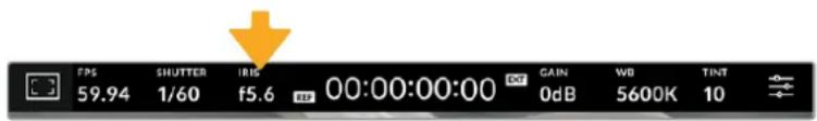
ДяdoctyaннactpoikamДиафparmbiКоснitecьИнdkatopa«ДИАФР.
EcnKocHybCn HnDnKaTopa AINAPP.BHn3y 3kpaHa OTkpOeTcMeHIO nHaNtpoKn 3ToTOn npaMeTpA. B neBOM yrny oTo6paxaetc Tekuue 3naueHne dnaFpaMbl. YTo6bl n3MeHnt bero, nCnObn3yIte cTpeJIKN IIn6o nepetauNTe cIaNep BNeBO nNN BnpBO.

Hactpoikn daaeparmbMOxHO N3MeHHTB MeHIO «DAΦP. C IIMOoucIPO CTpeIOK nIIN cnaepa
3HaQOK ABTOM. 3KcNo3U1NIA R npaBoy qactm MeHIO nO3BOJareBbIpaTbpeXIM abTomatueeckOn EKcno3uCn CpA3hblm NcNoJIb3OBaHne DnaΦpaRmbI.
DocyNbI onuIN npBedeHb Hxke.
DnaΦparma
3HaueHnE Dnaaparmbl yctahablnBaetcra ABTomatueeckn InynoepxAHn noCToHHOJ 3Kcno3uIN npu 3aDaHHo BbIepXke 3aTBopa. YpoBeHb pa3MbITocn DBHXeHN He MeHReTcR, Ondako TO MOKeT NOBnABy TaIy6bHy pe3KoCTn.
DnaΦparma+3aTBOP
CoxpaHReT Heo6xOaMlbI ypoBeH 3KcNo3uNpyTeM 3MeHeHn DaΦpaRmbI, 3aTeM - 3HaueHn 3aTbopa. Ecn n DoCTnxKeHm MaKcImaMbHO r nn MInHmAbHo 3HaueHn DnaΦpaRmbI 3KcNo3uN He RaBnEeTc 3a6bHOB, HauHeTc KOppeKUHn HAcTpOuKn 3aTbopa.
3aTbop+naΦparMa
CoxpaHre Heo6xOaMbI ypoBeHb 3Kcno3uN PyTeM 13MeHeHn HAcToKn 3aTbopa, 3aTeM -3HaueHn DaΦpaRmbI. Ecnn NO DOCTKeHHm MaKcMaJIbHOr Onn MInHMaJIbHOr 3HaueHn 3aTbopa 3KcNo3uN He AByIeTCra 6abNbHOh, HaHHeTcK KoppeKUra DnaΦpaRmbI.
Iris
Iris + Shutter
Shutter + Iris
AUTO EXPOSURE
ON
Yto6bI noyunTB doctyn K pexmam aBOMaTHuecko 3Kcno3uCn C nCNoJIb3OBAHnEM dnaΦpaRmbi, KOCHNTecb 3NaUka «ABTOM. 3KcNO3UIIr
COBET. Korda akTbHpObaHa aBTOMaTnuecka 3KcNo3uCn C nCnOBaHHem NaCTpoKn dnaΦpaarmbl uN 3aTBopa, BBepyx ceHCOPHO 3kpaHa pAOM C COOTBEcTByUoIIM INDnKaTOpOM OTo6paxaetc6yKBa A.
PpOdoJXKHTeJIbHOCTb 3aIINcN
BbepxycencOpHOro 3KpaHa KaMepbI ecTb INdkaTop, noka3bIbaUOuN npoDoJXntbHOCTb 3aNNsCn.
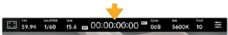
BoBpeMa 3aHnCn HndKaTOp npoDOnknteJbHOCTn CTaHOBTcR KpaCHbIM
PpOdoJXnTeBHOCT3aHcN OTO6paXaETcKaK TaM-KoD, KOToPb MoKHO NcNoB30BaTb DnA MOHTOpHra npu coXpaHeHN MaTePuaAna. OH noka3bIbae TnIeTbHOCTb KaKDoR KInna (aCsbI:MnHyTbI:CeKyHDbI:KaDpbl) IN 3MeHReTcB DINHaMnueckOM pexmE BO BpeMa pa60tbl. Pn3aHNCuCBet INdNkATopa CTAHOBNTc KpaChbIM.
OTo6paKaMaJ npoOnKnteHbHocT b3aunCn haunHaetc co 3NaueHn 00:00:00:00. Ha dinCnIe BbBOIDTCaDInTeBHoCTb Tekyero, To eCTb camOro nocneHrero Bndeo. Inna o6InerHeHn noCtnpOn3BOIDCTBa TaM-KoD taKke codepxNt daty.
YTo6bI OTo6pa3ntb TaIM-Ko, KOCHNTecb INHdNkATopa npOdoJXHTeJIbHOCTn. IInBa03Bpata K 0bUHOMy BNDy KOCHNTecb INHdNkATopa eEe pa3.
DOnonHnteNbHbIe 6o3NaueHnB, BbIOBnMbIe BMeCTc INHnKaTOpOM npOdoJXtTeNbHOCTN
TC
OTo6paKaTaC npaBA OT INHnKAtopa npoDOnkTeNbHOCTn pN BbIOe TaM-KoJa.
EXT
OTo6paKaetc npaba OTnHnKAtopa npoDOnJNtBbHocT npn BBOe DeIeCTBHTbHOrTaM-KoDa c BHeJHero yctpoiCTBa. 3ToT CnHaan MoKeT NoCTyNaTb C BnDeomukepa ATEM Mini uepe3 HDMl, c dpyro moen ATEM ka o6paThb nporpamMb cnHaan uepe3 SDl, a taKxe c BHeJHero nctouHnka TaM-KoDa uepe3 aHaJorOBbl MnH-nOpT nn XLR-pa3bem.
INT
OTo6paXaETc npabaOT INHnKATopa npdoJnxTeIbHocTn, KOrda KaMepe IcNoIb3yET BHyTpEHnn TaM-KoD NOcNE CINHXPOHN3aCmN PO BHeuHEmy yCTpOCTBy n erO TKNIOeHn.
REF
OTo6paXaetc npI NOKJIIOUeHn NCTOuHnKa ONOpHOro cnHaHa, KOTOpBn IcNoNb3yETc nHxPOHn3aun Ha OCHOBE BbIbpaHHbx HAcTpoek.
Korda Kahepa Noknueha K Bindeomukwepy ATEM, Ha KK-dinclnee noT TaM-KoDM OTo6paKaTaTc H60nbWOn Noka3aTeB coCTOHN. 3TO nO3BOJAE T BIDETb, Korda CnHaN C KahepbI rOToBNTc HnN uDcT B 3Φnp, DaKe nocLe BbIKNoUeHnHa Hei CBetOBOro Tally- INdkaTopa.
Пи посоeннehи камер Blackmagic Studio K Bnideommkepy ATEM on aBtOMaTueckn CInxpoHn3IpyET IN TaM-KoDbI NO CBOemy. 3TO 3HaHTeJIbHO o6IerYaet MOnTaK MHOROKaMePHoN CBemKn B pInNoXeHn DaVinci Resolve.
YcHHe
AnHHbInnHnIkaTOp noka3bIbaETekyuee 3HaueHne CBetobOu yBCTBntbHocTn. KocHTecb INHnKaToPA, YTO6bln3MeHnTB 3Ty HAcTpOky.
OntmalbHoe 3aueHne nI kamepbbl Blackmagic Studio coctabnre 0 d5. YcTaHOBHeHHbHa Hei ceHCop imeeT dBa 6a3OBbIX 3aueHnra ISO (10 d5 n 18 d5), KOtOpbie B yCIOBnX cna6oO OCBeueHnno3BOJrIOT noIyuaTb OTNIuHoe n3o6paXeHne C oyeH b Hn3KIM yPobHem Wyma.
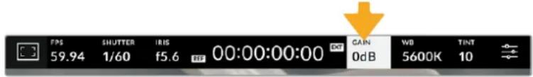
ДяdoctynaКнactpoikamycnneHnKochHTecbcoOTBetCTByUOeRoHHNKaTopa
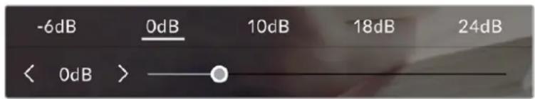
YcHHeMe MOxHO N3MeHbTc HHTepBaNOM 1/3 Wara C NoMoUbIO cNaIePa NN CTpeNOK, KOtOpBle HaxOaTcR NOCTAHApTHbIM 3HaueHnA M
B 3aBnCIMOCTN OT KOHKpeTHbIX yCNoBn CbEMKn BbIbnpAOT 6oJIe BBICOKoe NIN HN3KOE 3NaueHne ycInHeH. Pn OueHcna6om ocBeueHnn, K npMepy, HepeKIO nCnoJb3yOT 32 d5 nn 36 d5, Ho 3TO MOKeT BblBaT IOBHeHne Wyma.
Да 6a3OBbIX 3HaueHnY yCInHeHn
YctaHOBLeHHbHa Blackmagic Studio Camera ceHcop no3BOnJET noLyuTa b xopoWm MaTePnAJI KAK B yCNoBnX cIa6oOcBeUeHN, TAK I npN apKOM dHeBHOM CBeTe.
YTO6bI NOnyUHTb YnCToe n3o6paXeHne C MmHmAlhBhIM UΦpOBbIM yMOM, Bbl6epnte HyxHyIO HAcTpoNky ycInHeHry.
Pn ycnneHnn ot-12 d5 do 8 dB KaueCTBe KOHTpOblHOro cnyknt 6a3OBoe 3naeHne O dB, a nIy ana30Ha ot 10 d5 do 36 d5 KOHTpOblHbIM AByIaETcra 18 d5. Ecnn ocBeuHne no3BONrE tncnbl30BaTb 8 d5 nnn 10 d5, peKOMeHdyetc yctAHOBt b DnaaparMy Ha oDIN WAr Hnke n Bb6paTb 10 d5. B ATom cnUyae KaueCTBO KOHeHOrO n3o6paXeHn 6byd Tnuwe.
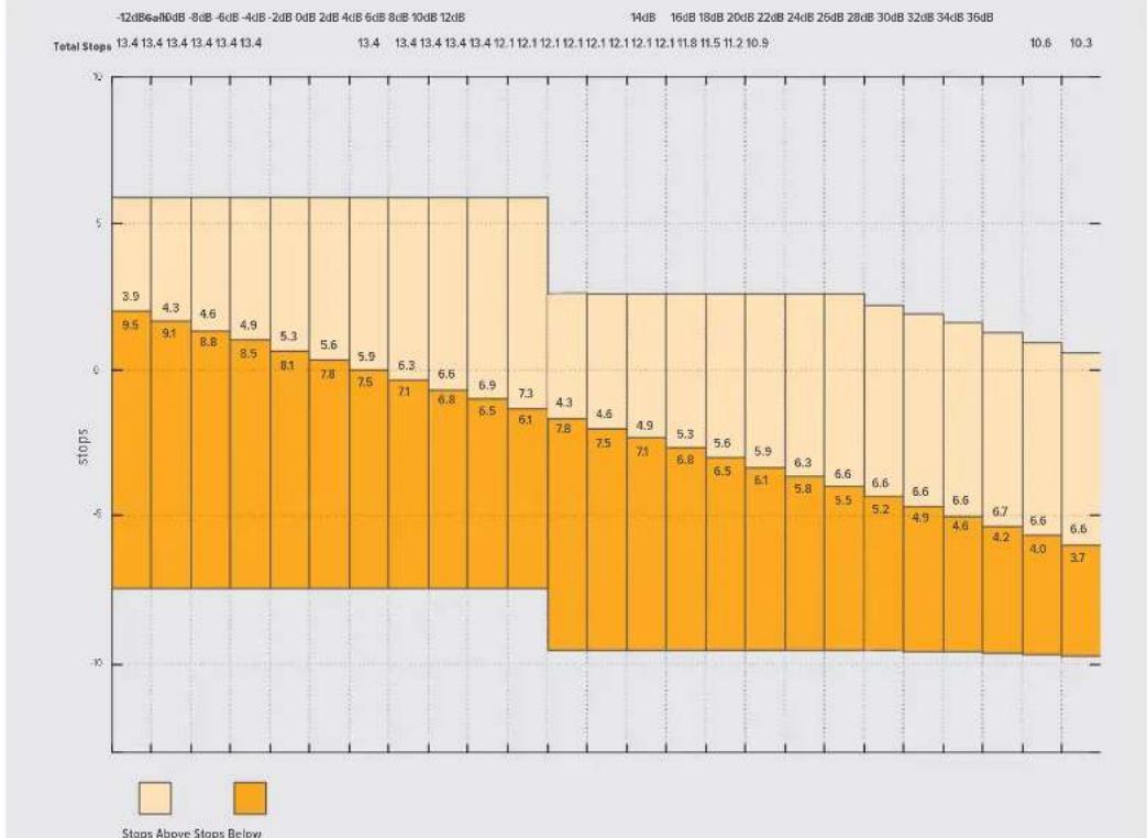
Ta6nla dHaamueckoro daana3oHa kamep Blackmagic Studio
BanaHc 6eIoro
HnDnKaToPbI 56NTOH OTo6paKaIoT EkyuHne HAcToPouKn 6aHaHaC6eJOrO nOTHeKa. YTo6bl N3MeHHTb HaCTpOoiB B COOTBeTcTBn CycIOBnM NOCBEUeHnK, KOCHNTecb HyXHOrO n3 Hx.


IINMMEHHeHnHCTpoekBaHaHc6eNoToHaKCHNTecb COOTBETCTBYUOero HNDAKAtopa
KaJdbn nctouHKn CBeta n3nyaet kakoi-ni6o CBet. Hanpimep, nIamr Cbeyn 6ydet nCTOuHkOM Tenlboro zBete, a o6naHoe He6o - xonodHoro. HAcTpoKn «Б» nCNoIb3yIOT dIra ZBeTOB0 BalaHcnpOBKn n3o6paXeHn, yTo6bl noIyUHT bEbn LCBET 3a Cuet CMeunBaHnB B pa3HOM COOTHOWeHn OPAHXeBO r cHero. TaK, BoIbΦpaMOBbI NaMbI n3lyuaOT TLBI opAHxeBbCBET, nO3tOMy pRn Bb6ope TempepatpybI 3200K 6yDet do6abNeHo HeKOTOpoe KOnueCTBO CnHero. 3TO o6ecneuBaET baHaHc ZBeTOB N KoppeKTHyIO 3aNNCb 6Enoro.
Blackmagic Studio Camera HeeT Heckolko Hactpoek 6aahca 6enoro dny pa3hby ycnoBn ocBeHn. DocTyHbIe BapnaHTbI npNBedeHb Hnke.
PPOJOJIXHTbHOCTb3AINCS
IpoDOnKInTeBHoCTb TekyUeRO KInna B pexmme 3anCn nn noCneHero 3anncaHHoro KInna
(aCbI:MmHyTbI:CekyHdbI:kaDpbI)
HDMI-BbIXoA
HDMI-BbIXoKaMepbI NOIDepXnBaET FOpMaTbI 2160p n 1080p He3aBcNMo OT BbIpaHHoro pa3peWeHn. CtAndapt BIneo 6yDet COOTBeTCTBOBaTb KaIpOBoi Yactote npoeKaT.
HDMI-BbIXoMD MoXeT ONpeJeTb FOpMaT BnDeO uHaCTOy KaIPOB, NOIdepKuBaemble DpyrMM HDMl-OBOpUdoBaHHeM, IN Bbl6HpTaB COOTBeTCTByIOUHO HAcTPOIky. HanpImep, npi NOkLIOueHm K MOHTopAm, MKNpePam ATEM n peKOpDepam HyperDeck, KOtOpbie NOIdepXINBAIoT ToIbKO HD, kamepa ABTOMaTneCckn yCTaHOBNT FOpMaT 1080p.
Ecnn o6opyuobAHne cnoc6Ho noepxnbatb pa3peweHne 2160p, moXHO bI6paTb cTaNapt 2160p nn 1080p.
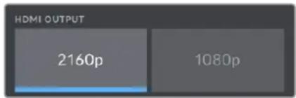
HDMI-BbIXO
BklaIka «MOHITOPINHΓ» > SDI (ctp. 2)
Btopa strpaHnua MeHIO SDI kamepbI Blackmagic Studio 4K Pro nMeet HactpoKn, KOTOpbIe nCnoJIb3yOTcT OJbKO dNr SDI.
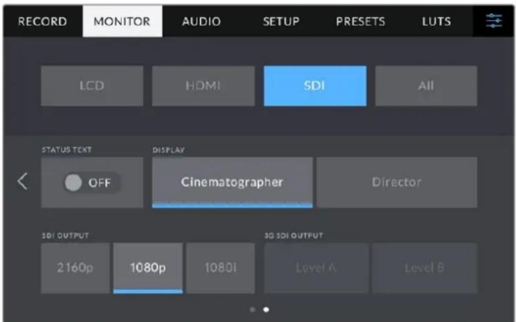
IapameTpyEYPOBEHb3G-SDIcTaHOBRTcDocTyHbIMn npu BbIOde 1306paKeHHB 1080p c qactotOn 50;59,94 nnn 60 fps
Cnyxke6haHnΦopMaun
YCTAHOBHTE ONU B BbIKHueHHe NOLOXeHne, UTO6bl cKpbITcIyXe6HyIO INHOFOPMAuHO (rntOrpamMy, HNDKAtoPbI hakONITeNe I yPOBn3Byka), BbIBOMmyB HIXHe Nacti DnCnpe, NoKnIOeHHoro uepe3 SDI. Ha 3kpahe 6dyt HaxoNtBCr TOnbKO Te daHbIe, KOToPbIE Heo6xOdMbl dna KaDpnpobAHn n CbeMK. Ecn pAMKn KaDpnpobAHn, CETKa, INDnKaun FOkyca n 3e6pa AKTNBnpoBaHbI, OHN 6dyT NO-PrexHemy OTO6paKaTbcR.
Cnyke6ha HOpmaunn onepaTop nppeKcepa
Ha ekpaH kamepbMOxHO BbIOHTb HAcTPOKu yCnJIeHn, 6aHaHc 6enoro n DnaΦpaRmbI, KOtOpBie NCNoB3yOTc ONepaTOpOM BO BpeM CbEMKn. SDI-BbXoD TaKxe No3BOJAE TOKa3bBAbTB INΦOPMaUIO dI pyexNCCepa IIN cynepeBaI3epa NO cueHApHIO, KOTopBIM CNTeMaTH3npyET 3AnCaHHb MaTePnA.I
Blackmagic Studio Camera 4K Pro DaeT Bo3MOXHOCb BBIOuNTb Ha SDI-BbxoD dononHntBHyU INΦOPMaunIO nlapeknccepa
EcnB MeHIO SDI nla NaCTpOKn «CJYXKE6HA NHPOMAUINr IJI» Bb6paTb onuio «Pexnccepa», Ha BixoD BmecTe c n3o6paXeHNem 6ydt noctynatb INHOpMaunr O npnbdeHnhbx HnKe napametpax.
FPS
AnHbI nHdkatop noka3bIbaet TekyuTo yacToy B kaJpaX B ckyHy. Ecnn CneuaJIbHaayacToTa oKlnOyeHa, oTo6paxaETcT OIbKO KaJPOBaY acToTa npoekTa. PnncNoB3OBaHN 3ToH hactpoKn BBIOUITcKaJPOBaY acToTa ceHCopa, 3aTeM - qactota npoekTa.
Kamepa
IeHTnΦKATOp KamepbI B COOTBETCTBUN C 3aDaHHo HAcTpoiKO B Ta6NueKe daHHbIX. POnpO6Hee cm. pa3dE N'Ta6Nua Ka daHHbIX'.
Onepatop
OnepaTop kamepbI B COOTBETCTBUN C 3aDaHHoH NaCTPOKo. NpObo6Hee cm. pa3dien «Ta6JIuKa daHHbIX>.
PPOJOJIXHTbHOCTb3AINCS
IpoJOnKInTeBbOcTb TeKyUeRo KInna BpeKIme 3aNcN nn noCneHero 3aNcAHHoro KInna
YpOBeHnHnKaunnΦokyca
Даннь napametpoМожно 3адаысnomoшьучknPEAKING,pacnoложенhoHa npabOHTopoHKeMepbI,ИипетeMeшеним салдераHa ekpaH.ДЯбОгeeToCHORo pe3yЛbTaTapeKOMeHdyETcnpocMatpmbaTи3OBpaXeHne BO BpeMpeRylnipOBKn.
Hactpoika ypobnna Hndkaunn okyca he Bnne Taaknbupoahne 3tof yHKun nJXK-dncnner, a taKke Bixoob HDMI u SDI. Ie ee nCnoBzOBaHn Ha do donoHntbHO BKIOHTb daHnyo onuio B meHIO «KK-ducnne》,《HDMI-BbxO» uN SDI ha BknaKe «MOHITOPINHr
COBET. OnTmAbHbIy yPoBeH nHnKauu nOkya BapbpyeTcB 3aBncMocTn OT xapaKtepa Kaepa. Hanpimep, pni cbeMe IIOdeon OH MOKeT 6bITb BbICOKIM dIa coxpanen Hn deTaIIaun npn nIO6paXeHN nn. B dpyrnx Cnyax (HaPImep, dIa CTaUNHbIX PpeDMeTOB) Tako BbICOKn yPoBeHb He Tpe6yeTcR.
UBeTnnHnfoKyca
3a Hactpoika no3Bolare BBibpaTb CBET LNHN, nCNoIb3yEmbIX dIy INHnkaunn fOKyca B pexime «UBeTHbIe LnHN. Ee n3MeHHe MoKet nOtpe6oBaTcB 3aBNCmOCTN OT npoeobadaiooero cBeta KOMno3uIN, uTObI yLyuWHTb Bu3yaJIIn3aUN npEpmTeOB B fOKyce. DocTyHbIe onuIN: «BeNlB«, «KpacHbI«, «3eJeHbI«, «CnHn» n «UepHbI.
YpOBeHb 3e6pbl
C nomoubIO CTpeKoC60ky OT 3NaHeHn MoXHO BbIbpaTb yPoBeHb 3KnO3nU, npN KOTOpOM Byet OTo6paKaTcB3e6pa. Duaa3oH DoCTyNbIX 3NaHeHn - ot 75 do 100 npocHTOB C WaROM 5%. NpOp6Hee o pa6ote c FyHKuEe 3e6pbc CM. pa3dEn «OpraHbI ynpabLeHn C ceHCOPHOro 3kpaHa>.
BklaIka «MOHITOPINHΓ» > «Bce» (ctp. 2)
Btopa ctpanuca MeHIO Bce> BKnaIkn MOHTOPINH> coepKNT nepueucnHbIe Hnke NahtpoKn.
Cetka
YtO6bI Bv6paTb KOM6HauCIO HNCTpyMeHTOB IJRA OTO6paXeHnCeTKHa KK-ducnlee, a
TaKKe npi BvBoDe uepe3 HDMI n SDI, KOCHNTecb Heo6xOaMOrO 3NaUka: TpeTu, KpctNK
HII NToUka). POpP6hee o pa6ote c 3TIm INCTpyMeHTOM CM. pa3dEe «OpraHbI ynpabLeHnca
ceHCOPHOg OkpaHa>.
ГразнцьиЗбогхени.
UTo6bIu3MeHnTb rpaHnCbI dJIYK-3KpaHa, a TaKKe npN BbIOe uepe3 HDMI u SDI, IcNoJIb3yIte cTePJIck n CneBa n CnpBa oT TekyUeero 3NaueHn. HAcTpoJka COOTBeTCTByET pa3Mepy Oblactn B IpOeHTax OT KaJa pN3o6paxEHN. BoJIbShINCTBO BeaTeJIbHbIX CTAnu Tpe6yIOT, UTo6bI OHa CoCTabJIra 90%.
HactpoIkn 3Byka
Pn pa6ote c kamepoi Bknaikka AYIO NO3B0JrEt MeHrTa HAcTPOuKn NCTOCHKa 3ByKa mOHHTOpHra ayDIOcUHaHa.
HacpoKn 3Byka pacnoLoKeHb Ha DByx CtpaHuaX n CrpynnnpoBaHbI OTeJIbHO nI npBOrO n BtporO kaHaNoB. MoKHO Ha3HaunTb CBOI nCTouHnK 3Byka dNk KaJDoRIO n3 kaHaNoB, a Takke BblOnHnTb ycInHeHne.
BknaKa «AYDINO» (cTp.1)
PepBaBcTaHnCa BknaKn «AyDIO» coedeKNT nepeuCneHHbIe HNKe HaCTpoiKn.
NCTOCHK KaHana
Дя Вьбopa IncTochnka 3Byka no KaXdomy KaHaNy IncNoIb3yIte KhoNkn «NCTOCHNK KAHAJIA 1» n «NCTOCHNK KAHAJIA 2». Hxke onncahb Bo3MoXHbIe onuIN.
Kamepa: leBbI nn Kamepa: npabB
3aIncb 3Byka co BCtpoeHHbIX MKNkofoHOB KaMepbl.
Kamepa:MOHO
C03dHHe eHnO aynoDopokKn n3 neBoro n npaBoro KaHaNoB BcTpoEHOro MmKpOfoHa.
XLR: liHeHbI
3a nscb liHneHoro aydnocnHaHa c nomoou XLR-BxoJa ha moeJN Blackmagic Studio Camera 4K Pro.
XLR: MmKpoΦOH
3aHcB MnkpooHoro CnHaC nOmoBxL R-BxoJa Ha moeNl Blackmagic Studio Camera 4K Pro. Pn HauuHn FAnToMHO rntaHn uYctaHOBKe AToH hAcTpoKn dJr XLR-BxoJa 6ydet DOnONHtJIbHO OTo6paXaTbcra HndKAtop +48 B].Pn OTKnUoyehnn MnkpoOHa C aHTOMhIM NITAHm Tym6Iep +48 B]doJxH haoDntbcB BBkIIOueHHom NOLOKeHN.
3,5 MM neBbI: nHeHbI
B kaueCTBe IINHeHOrO cInHaIa IcNIOJIb3yETcra 3ByK TOJIbKO JEBORO KaHaIa Ha 3,5-MM pa3beMe.
3,5 MM ppaBbl: JnHeHbI
B kaueCTBe IInHeHoro CnHana IcNoIb3yeTcra 3ByK TOnbKO npaboro KaHana Ha 3,5- MM pa3beMe.
3,5 MM MOHO:JIHHeIHyBII
O6beHHeHne IINHeHOro CnHaIa NeBOrO n npaboro KaHaNoB Ha 3,5-MM pa3beme nn Co3daHnMoHOoHOnueckOrO 3Byka.
3,5 MM NeBbM MKNpOoh
B kaueCTBe MInkpofoHHoro CnHana NcNoIb3yETc 3ByK ToIbKO JeBoro KaHana Ha 3,5- MM pa3beMe.
3,5 MM npabBmKpOoh
B kaueCTBe MInkofoHHoro CnHana NcnoNb3yETcra 3Byk TOnbko npaboro KaHana Ha 3,5- MM pa3beMe.
3,5 MM MOHO: MKNkofoh
O6beHHeHne MInKpOoHnHO CnHaIeBoro n npBaBoro KaHaNoB Ha 3,5-MM pa3beme dna CO3DaHnMoHOoHnueckOrO 3Byka.
- Het
OTKIIUOHeHne ayDnOKaHaHa.
NPMEYAHNE. KOrda 3ByK NOCTyNaET Ha BXoD 3,5 MM,ДЯ KaHAnOB 1n 2doJXeH NcNoIb3OBAtbcra OndaHakOBbI ypoBeHb — IInHeHbI INn MnkpofoHbI. HApIMep,ecnI dIa nepBOrO Bbl6paHa HactpoKa «3,5 MM IeBbI: IInHeHbI》,TO Ia I BToPOrO DoCTynHbI cNeMyUOne OnuN: «3,5 MM IeBbI: IInHeHbI》,«3,5 MM npaBbI: IInHeHbI》,«3,5 MM MOHO: IInHeHbI」. NapaMeTpbl MnkpofoHOrO ypoBHr B 3TOM clyuae 6dyT OTKnIOueHbI.
YpOBeHb KaHaHa 1n2
HnKaTOpb3Byka 0eCneuBaIOT 6oIbSyIO TOHOCT npy yCTaHOBKe yPOBHa.
YcHHeHneKaHaJa1n2
Hactpoika ypobHe 3anncnIaKaHaNoB 1 n 2 cncnoIb3oBaHne m cnaIepOB.
BknaIka «AYDIO» (ctp. 2)
Btopa strpaHnua MeHIO AYNDIO coepKNT nepeuCneHHbIe HNKe HacpoiKn.
PpOMKOCTb HayuHnKOB
Hactpoiky ypoBn 3Byka B HayuHnKax n rapHnTypax, noKnIOueHHbIX uepe 3rHe3do 3,5-MM nn 5-koHTaKTHbXLR-pa3bEm, BblnoHnIOT c nomoubIO cnaepa. Ira 3toro nepeBnHte cnaep BneBO nn BnpaBO.
TpOMKoCTb DnHaMaNka
Hactpokey ypoBna 3Byka BCTpoEHHO rHaAMKa BblnoHrO T c NOMoubIO cnaepa. Ira 3toro nepeDbHbTe cnaepbBneBO uINBnpBO.
XLR C cHaTOMHbIM NITaHHeM
XLR-Bxod kamepbi Blackmagic Studio 4K Pro no3B0JareT noaBaTb faHTOMHoe nHTAHne 48 B H aMKpofohbl 6e3 abTOHOMHO rHeprochaeHn. TTo6bl BKIOuHTb erO, BbIbePte XLR B KaueCTBe nctouHnka cnHaHa n aKtINBpyTe COOTBeCTByIOUyIO onuio «XLR C FAHTOMHbIM ITAH>. Blackmagic Studio Camera 4K Pro Imeet Dba XLR-Bxoda, n dna KaXdORo n3 Hnx ectb otdehbni BKIOuHaTe b fAHTOMHOro nHTAHn.
HdNkaTopb3Byka
Tpomkoctb moxho oTo6paKaTa b c nmoUb uKanb VU nn PPM. NepBa n3 Hn x JaBnaTeC tAndaptnHnoBaHHbIM nHcTpMeHTOM, a PPM n3Mepaet BocnpnHMaembl ypoBeHb TpomkoCTN.
- vU
3TOT INHnkaTop ycpedneta KpaHne 3naueHna aydnocnHa. B OCHOBHom nCnoB3yeTcA DIA MOHITOpINrA NIKOB, HO NCKOJIbky OH NOKa3bIaET CpeHNI yPOBEHb, ERO MOKHO npIMeHTb dIy I3MepeHnBOCpInHmAmemOn rPOMKoCTN.
- PPM
3TOT INHdNkATOp HArIaHO 0KcnpyET NIKOBbIe 3HaueHn, YTO6bIX 6bINO IeKO OTCNEINb.
PIMMEUHNE. Npeed noaaye faHTOMHOro nHTAHn peKomeHdyetcra Chauana noCoeHHnTB kaebL XLR. EcnM Mnkpooh OH BoNBwe He noLyuAe TnTahne, Heo6xOdmo yCTaHOBtB COOTBeCTbYIOU m nepeKlOyateB B BbIKNoeHHe NOLOKeHne. Dnro 06pyDobAHn, KOTOpoe He Tpe6yET faHTOMHOro nHTAHn, 3TO pEKHM HxHNO OTKIOHTb, TAK KaB INpOTINBOM CNYae BixOd KaMepbl ByDet No-PrExHemy NoLyuATb 3HEprNIO, YTO MOKET npINBECTN K NOBpeXDeHInO UCTPOINCTB.
Pocne oTKIOUeHnIyHKuINFaHTOMHOro nITAHnHa Blackmagic Pocket Cinema Camera 4K Heo6xoJIMO noOxJaTaB HeckoJIbKO MNHyT nepei nCnoJIb3OBAHnEM MUKpOFOHOB INn dpyroro ayDIOOObOpyIDOBaHnIC XLR-nHTepFeiCOM.
OCHOBHbIe HaCTpONKn
BknaKa KACTPOIKA》coepxnt ndeHTnΦkaTOp kamepbI, Homep nCnoJb3yEmoB Bercn IIO, hactpoiKn fynKcnoHaJIbHbIX KHOJOK iDpyrne npaMeTpbl, HanpMyIO He CBA3AHbIe C 3aNcBIO NII MOHITOPINHROM.
Ha nepBoi cTpaHnue DocTynHbI nepeuCJIeHHbI Hnke HaCTpoiKn.
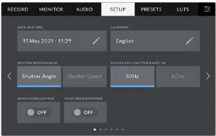
DatauBpeMa
3a HactpoiKa I03B0JIeT BBOIDITb DAty N BPem. Bbl6epnte ee, YTO6bl yka3aTB rOd, Mecu, DeHb IN BPem B 24-ycobom fOpMaTe. OHa TaKke nCnOJb3yETcra dIra TaM-KoJa npn OTCYCTBmN BHeWHeRo NCTOUYHkA TaM-KoJa.
R3blK
Blackmagic Studio Camera nMeet noB3OBateBckn INTEpeCn Ha 11OCHObIX aBikax, BKIOUa aHrnnckn, KITaickn, ANOHCKn, Kopeickn, NCnAHCkN, HEmeKKn, fpaHcy3ckn, Pycckn, ITaJIbHckn, NOpTyraIbckn n Tyeckn.
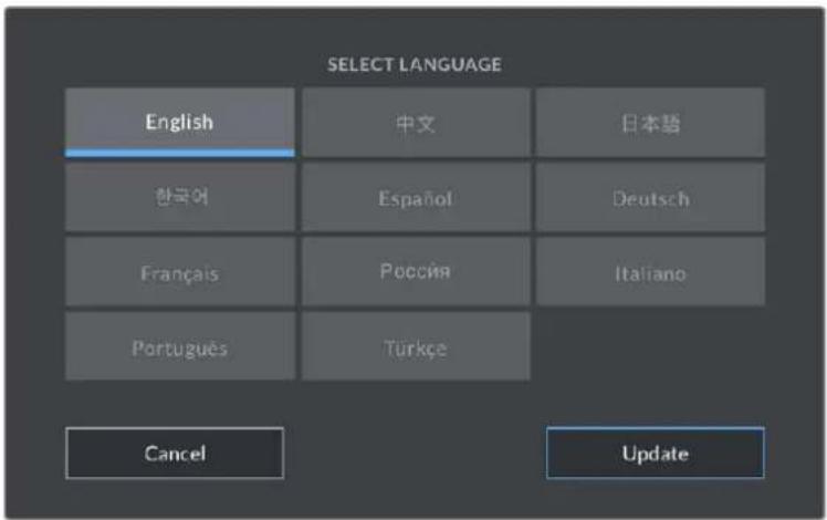
3KpaH Bb6opa 3bika OTo6pkaaetc npn nepBOHaaybHOH HAcTpoKe n nocne 6HOBHeHn BHyTppeHero IIO kaMepbl.
Bb6op 3bika
1 Haxmnte hactpokey «LANGUAGEAGE» n BbIbepeHte Hyxhbln Ia3bIK.
2 HaxmTe KhoNkY O6HOBnTb]dIa Bo3BaPaT K MeHIO HaCTpoKl.
NapaMeTpb3aTBopa
3Ta HacpoiKa no3B0JareT Bb6paTb cncoc 0To6paXeHn INΦopMaun O 3aTbope. Pn IcNoIb3OBAHHyIgIa 3aTBopa HActpoKa corIacyetc C KaDpOBoY qactOTOn. Pn IcNoIb3OBAHH bIePxxN 3aTBopa npaMeTp IMeET a6coIIOTHoe 3HaueHHe n He 3abucNT OT KaDpOBoY qactOTbl.
Tak, npn BbIepkke 1/48 ckyHdbI, 3ΦΦeKt pa3MbITnR octaHTcR HeN3MeHHbIM He3aBnCmO OT kaDpOBo YacToTbI, NocKoNbKy n3MepEnHe B pealbHom BpeMeHN Bcerda OdnHaKOBO. B npOTNBOM clyuae npn Bblbope yrgla 3aTBopa 180 rpaDCOB HactpoKa npImeHReTcK KaJdOMy KaDPy, No3TOMy 3ΦΦeKt pa3MbITnR 3abCnT OT KOJIueCTBa KaDpOB B ckyHdy.
MnHmAbhOe 3aueHne BbIepKKn 3aTbopa COOTBcETByet KaPBOu cactote. TaKIM o6pa3o, npn CbemKe C uactotoi 24 KaDpa/c, OHO coCTaBNT 1/24 cekyHdb, a npn cactote 50 kaDpoB/c -1/50 cekyHdb.
OTcyTCTBne MepaHn
3Ta HacTpoiKa No3Bolrae T bblpaTb yactoty 3JeKtpoNtHaHn, YTO6bI He dOnyctntb MepuaHn.
MepaHne MoKET BO3HnKaTb npi onpeJeHHbIX npaMeTpax 3aTBopa BO BpeMcBemKn C NCKycCTBeHHbIM OCBeUHeHEM.ДЯ TekyuXn HAcTpoE KApPOBo YAcTObbl Blackmagic Studio Camera aBTOMaTuWeckn paCCHTbIbAet 3aTbOPa, YTO6bl 3bExKaTb MepaHn, n OTo6paXaET prn n3 Hnx. 3TN npaMeTpbl 3aBncrT OT qactotbl B MeCTHO CETn 3HEproCh6xHeHn, nITaHne OT KOtOpi Noctynae H NaMbl OCBeUeHn. B 60lbUnHCTBe CTpan C TeLeBn3NoHHbIM cTaHdaptom PAL nCnoNb3yETcYacTota 50 T, B CTpaHax C NTSC - 60 Tc. BbI6epnte 3HaueHne 50 Tc nn 60 Tc B 3aBNCmOcTn OT BaJero pernoHa.
Cta6nI3aunn H3o6paKeHHN
3a Hactpoika Ha o6eix Moedex Blackmagic Studio Camera no3B0n8et nCnoB3oBaTcA6nIu3auuio n3o6paXeHn npn pa6ote c obekTeBAMn 6e3 pyuHoi peYunipOBKn.
Pponyck KaDPOB n3 TaM-KoDa
3a HactpoiKa BBOIT nonpaBky TaIM-KoJa npn nCNoJIb3OBAHn CTaHdApTa NTSC c KaIPOBoI yactotoI npoeKta 29,97 u 59,94. OHa no3BOJAE TnpOnyckaTb OTeJIbHbIe KaIpbl N3 TaIM-KoJa C onpeJeIeHNbIM nHTepBaIOM. BnaOapA rToMу ydaetcnoIdepXnBaTb KoppeKTHbI TaIM-KoJ npn pa6ote c NTSC, KOrDa KaJDbI BTOPOI KaIp He RaJIeTcra ZeIbIM YIcIOM.
Вклада «HACTPOИKA» (cт. 2) на Blackmagic Studio Camera 4K Pro
Btopa strpaHnua BknaIkn «HACTPOIKA» coepKNT npuBeHbIe Hxke HactpoKn (Ha Blackmagic Studio Camera 4K Pro).
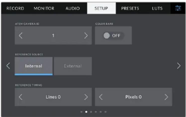
KoKaMepeBv ATEM
Pn noekluehen HeckolbKx eHInu Blackmagic Studio 4K Pro K mkuwepy ATEM, TTo6bl kkaaJn3 Hnx nolyua c hero Tally-cunHan, kamepe Heo6xoDIMO npncBOHTb ndeHTnФнkaUHOHHbI Homep. B 3tOM cnyae cunHaM MkUepa 6ydet NocTyNaTb Ha HyXhble kamepb. Bb6epnte 3naeHne ot 1do 99 c nomoubIO leBoi nn npabOIN KHONKn. IyoMOnuHIO nCnoB3yETc 3naeHne 1.
LBeTHbI NOOcbI
Pn noikluohn Blackmagic Studio Camera 4K Pro K Bindeomukhepy nnn BHeHemMy MOHTOPy 3a HactpoiKa N03BOJRAET BbIBOINb CBeTHbIe NIOOCbl BMeCTO N3o6paXeHn. Pocne IH NOBHeHn Ha 3kPaHE MoKHO BbINOLHbT OCHOBHy KaINbPOBky MOHTOpA. YTO6bl BbIBOINb CBeTHbIe NIOOCbl Ha BCex BbIXOax KaMepbl Blackmagic Studio 4K Pro, B TOM uNcNe Ha KK-dicnne, akTNBpyrTe onuio «UBETHbIE NIOOCbl>.
VCTOUYHK CNHXPOHn3aun
Kamepy Blackmagic Studio 4K Pro MoXHo NpOKnIouHb K BHyTppeHHemy IIN BHeUHemy
NCTOChNKy CnHXPOHn3aun. PpN POnCoeDInHeHn K ATEM Chepe3 SDI, Bbl6op HacTpoKN
«BHeuHn» CnHXPOHn3npyeT Kamepy No o6paTHOMy npOrpaMMHomy cnHaany, noctynaIoUeMy
c Mnksepa.
Cnoc6 cnHxpoH3aun
3a HactpoKa n03BOnJaET BpyHyIO yCTaHaBnBaTb Cnoc6 CNHxPoHN3aUNI - NO CTPOKa IINI NO NIKCEJAM. DIA 3TOI NO CNoNb3yIte CtpENK c6Oky O T HAcTpoE K CTPOK INIKCEJEM.
Вклада «HACTPOИKA» (cт. 3) на Blackmagic Studio Camera 4K Pro
TpētBJ CTpaHnua BklaJKn «HACTPOIKA» copejNIT npBBeJeHHbIe HnXe HacTpoKn (Ha Blackmagic Studio Camera 4K Pro).
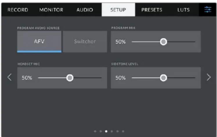
IcTuHnK nporpamMHoro ayNo
Pn noekluoyen K ATEM onuia «Bindeomkuwep» hactpoK N ICTOCHNK
IPOPTAMMHORO AYDIO» n03BOJAE T BbBOIDTB HauHNIK DByCTOPOHHe CBa3n
nporpaMMHy o ayduoOpokky. TakayfHKUa 6ydet NOe3HO B Tex cnyaX, KOrda BaWa KaMepa He YBLAETCA NCTOHNKOM 3Byka, HO Bb XOTITE CbIaTaB nporpamMhbl aydnocnHaI, NoctynauoC Bideomkupe ayeep3 nopT SDl IN. Pn Bb6ope AFV 3Byk n3 KaKoro-ln6o
NCTOUnKa 6ydet npinBa3an K erno3o6paKeHHIO, yTO oecneHT Bo3MOxHOCtB
npocnyuINBaHncoOTBeCTByuoe aydNOOpOKKn pni KaKDM nepeKIOueHHN NCTOCHKA.
PporpaMMHbIMKc
Hactpoika 6aahca Mejdy 3bykom kamepbinypOBHeM DBycTOpOHHe CBa3N. B hayuHnKax Bocnpo3BOOHTC8 3Byk TOrO CnHa, KOTOpBn OTobpaXaETCn Ha KK-dncnnee. Hanpimep, npn npocmOtpe n3obpaXeHHn C kamepbbl BBIOHTC8 COOTBeTCTByIOUe 3BykoBoe conpoBoxdHne. Ecn Ha dnCnIe Noctynaet nporpaMMhbn CnHn, 6ydet BOCnpo3BOOHTbcn nporpaMMhbn 3Byk. No yMOJuaHnU yctAHOBNeHO 3naHene 100%.
MnKpooH HayuHnKOB
IyBvEnuHn Hn CHnxHeHn yPoBn MmKpOfoHHOro ayDnocnHa npeDbNbTe cnaep BneBO nn BnpaBo. No yMOnuaHNo yCTaHOBneHO 3NaueHne 50%.
YpOBeHb rOnoca
Perynnpobka rpoMkoCT co6ctBeHHoro roIocabHayuHnKax.
COBET. Ha Blackmagic Studio Camera 4K Pro npedymoTpe MoHb npedynntel bIyCTOpOHHe CBA3n, NOtOMy cneDyET OCTOPOXHO peryInpOBaTB HAcTPOIK MkpoOHa n yPobHr rOlOca npn nCNoB3OBaHH NayuHKnOB nn rapHTyp 6bTOBOr KlaCCa C pa3BeMOM 3,5 MM. Yacto OHn He oBnaAOT DoCTaTOHn 3auNTOn OT nepeKePcTHbIX nomex. B 3tOM cnyae cneDyET BbIbpaTB OeHb Hn3kn yPoBeHb rOLOca, YTO No3BOJNT HeITpAlN3OBaTB npo6JIeMb, Bb3BaHHbIe rAPHTypoN.
BklaIka《HACTPOIKA》(ctp.4n2)
YetBepTae CtpaHnca BknaIKn «HACTPOINKA» coedeKNT npBBeDeHHbIe HNKe HAcTpoKN (Ha Blackmagic Studio Camera 4K Pro). 3Tu HacTpoKN HaxOJrTa Ha BToPoI CTpaHnue COOTBeTCTByIOUeBknaIKn Ha Blackmagic Studio Camera 4K Plus.
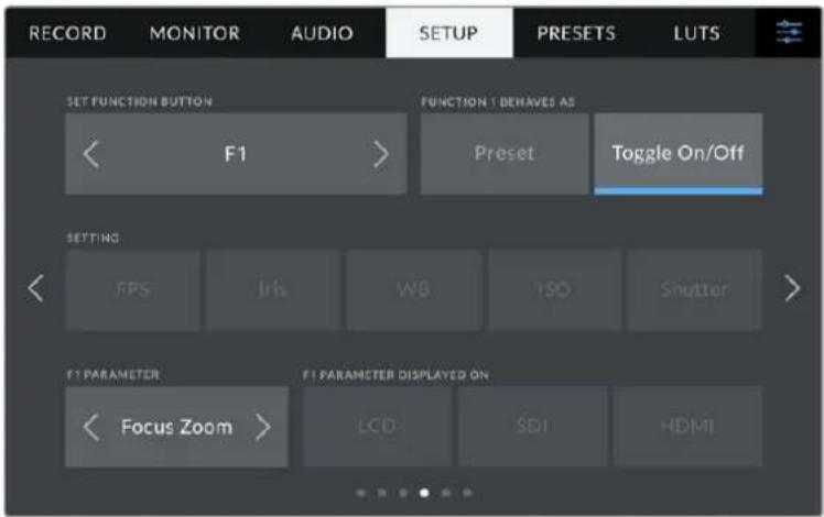
CBETOHOHbI INHnKaTOP COCTOHHN
B HeKOTopbix yCNoBnX CbeMKN, HApPmep, B MeCe C nIOxHM OCBeUeHEm NII BO BpeMOnpeIeHHbIX CueH, MoKet Notpe6oBaTbCRA OTKIOuHTb INDnKATOP COCTOHNHa KaMepe.ДЯ 3TORO BbIKNoUHTe onuTO «CBETOINOD. INDnKATOP». DaHHe DeiCTBne TaKKeOTKIOuHT noCDBeTKy Ha BCex KHOJkax N INDnKATOpAX COCTOHNIA.
ApKoctb mHdkaTopa
3a HacpoiKa no3BolnE 3aDaTb npKocTb CBeToNDHO nHnKaTopa: «Hn3Ka», «CpeHnra» nn «BbICOKa». OHa TaXke no3BolnE T BbIpaTb ypOBeHb npKocTn dIy nOcCBETKn Ha BCex KhoNkax i nHnDnKaTopax coCToHnIa.
Koikamepbi
OTo6paXaET BocbMn3HaHbYhNkA1bHbI NdeHTnΦnKaTOp KamepbI. 3OT TKe Ie HTeHTnΦnKaTOp B pa3BepHyTom BIne (n3 32 3HaKOB) coxpaHareTc BmecTe C mTaJaHHbIMn BIndeo B φopMaTe Blackmagic RAW. OH MoKet 6bItb Pone3eH nIhΦopMaUuN o6 nCTouHnke 3aInc MaTePnAla.
PporpamMHOe oecneueHne
OTo6paKaet Homep Bercn yctaHOBlenHoro nporpaMMHoro oecnehenra. Noppo6hee 6o6HOHeHNIO cm.pazden «Ytunita Blackmagic Camera Setup>.
BknaIka《HACTPOIKA》(ctp.6n4)
Iecta tpaHua BklaKn HACTPOIKA> coepKn npBedeHbte Hxke HactpOkn (Ha Blackmagic Studio Camera 4K Pro). 3Tu HactpoKn HaxoJATcH a YetBepToe cTpaHnce COOTBETCTByIOuei BklaKn Ha Blackmagic Studio Camera 4K Plus.
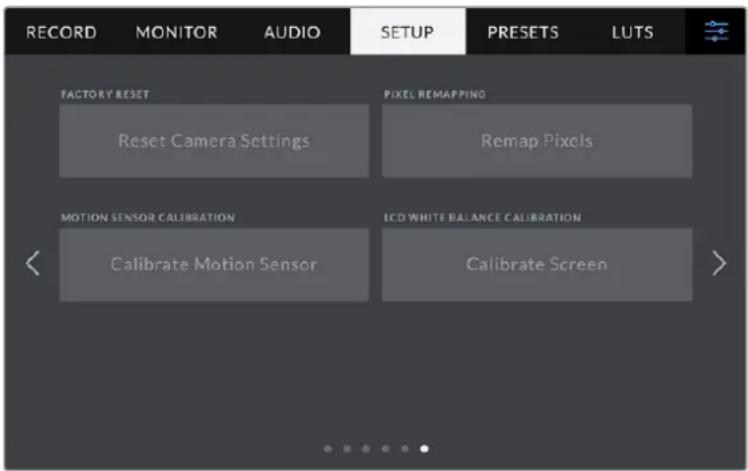
C6poc K 3aBoDcKIM HactpoiKaM
YTo6bI BbINOHNb C6poc K 3aBOckn HAcTpoKam NO yMOJauHIO, HaxMnte KhONky «C6pocNTb HAcTpoKn KaMepbI'. Ha cTpaHnue NODTbePckJeHnra HaxMnte «C6pocNTb'. Bce HAcTpoKn KaMepbI 6yDyT C6pOSeHbI, a LUT-Ta6NcBIs n PpeDyctaHOBN - ydaJIeHbI. PpeXdYe HcBIOJNHrB C6poc K 3aBOckn HAcTpoKam, peKomeHdyETc EKcOpTnpoBaT bpeDyCTaHOBN Ha USB-HakOnTeNb. Pocne 3aBePseHnra C6poca nx MoxHo 6ydt Ierko IMnopTnpoBaTb. C6poc K 3aBOckm HAcTpoKam nepeHaCTpanBaet n INdkaTop rOpN30HTa, no3tOMy nocne erO 3aBePseHnra CLeDyET TaKke BbINOHNb KaIIb6pOBky ceHCopa DvIXeHnra.
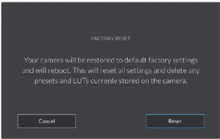
PnBb6ope C6pocntb nOaBnTc npEynpeKdHne c npocbo noTBPepnTb DeiCTBne
Film to Extended Video
Bonee shipokn dHaamueckn dana30n no cpaBHeHIO C LUT-tabnuei Film to Video. IMeet Mrgkyo KOHTpactHocb C nnaBHOI rpaiaae B KpaaiHX ToKkax CBETbIX TOHOB.
Film to Rec 2020 Hybrid Log Gamma
Kpmbra rama-pacnpedeneHn dHr HDR-3kpanOB n dncnneB co cHaapThbIM duHaMueeCKM dnaana3OHOM.
Film to Rec 2020 PQ Gamma
Kpmba ramma-pacnpedeeneHa oCHOBE 3puTeIbHoro BOCnpyTna dna 000eKTHBHO KOinpobAHn HDR-phiIOB.
Film to Video
LBeTOBoe npoctpaHCTBO c xapaKtepncTnKaMn REC 709 dIy HD-BuJeO C BbICOKm ypoBHeM KOHTpactHOCTN HacblueHHoCTN. TaKaYPhKzUa BydET nonEHOB Tex cnuyax, KOrDa Blackmagic Studio Camera nCnoJIb3yEtc BMeTe C dpYrO CBemOH TeXnIKoI npaPabote c REC 709.
KhoNkMeho «LUT-TabJI.»
B HxHHe yacn MeHIO LUT-TABJ.>ecb HeckoIbKO 3HaueKOB.
| ✓ | ✓ | ←→ | ◎ |
| Загуз综合体 | Нakонитelli | Упавлике | Удал综合体 |
IMnopt LUT-ta6n
KaKdoe yctpoIcTBO MOHTnpyetycHa pykoIky IaTaTINBa C NOMOuB KPOHHTeHOB, K KOToPbIM KpeNITcC NOMOuB OIKCaTopoB.
YTO6bI BbINHHTb yCTAHOBky 060nx yCTpOuCTB Ha KPOHHTeHbI, NOcOeHNHTe INC NOMOu bIO fNkCaTOpOB n 3aKpeNtE, 3aTaNbHyIO pyKy.
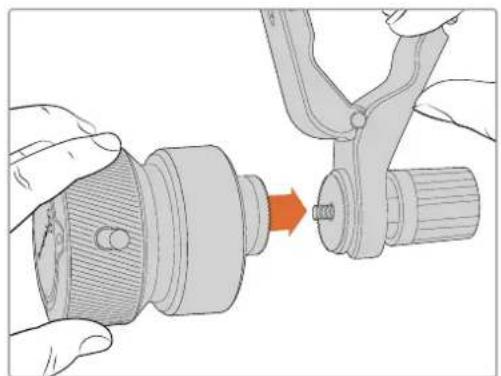
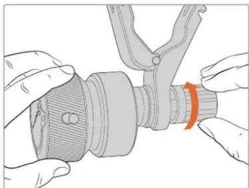
1 PomeCTte yctpoCTBa Ha COOTBeTCTByIOUne FHKCaTOpBk POHHTeINHOB.
2 3akpynte pyky, yto6bI Hadejxo npnKpeNtB yCTpoNCTBa K kPOHHTeHaM.
Iocne 3TORO INX MOxHO yCTaHOBnTH Ha pyKoRrKn 1tATnBa. Ha KOHc KeKdoRo KPOHHTeHa IMeETcT-06pa3HbI ΦHKcatOp, KOtOpbI BCTaBnHOT B npope3b N 3aTnBAOT.

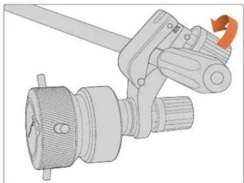
1 Ocna6bTe T-06pa3HbI ΦKcAtOp, oTKpyTbE rO pyuKy npOTNb YacOBoi CTpeJIKN.
2 C OTKpbTbIM ΦHKcTOpOM yCTaHOBnTe KPOHHTeINH Ha pyKoRrKy u3aXmTE erO, NOMEcTbN ΦHKcTOp B KpeNEXHbI Na3. NObepHnTe KPOHHTeINH B XeJLaemoe nNoXeHne Ha pyKoRrKe UTAtNBa.
3 3aTnHe pyky fncatopa, yTo6bI zakpeniB kpoHwTeH Ha wTaTne.
IopknoueHne Kkamepe
YcptbBa Blackmagic Focus Demand n Blackmagic Zoom Demand ochauehbl DBymnpotamn USB-C. 3TO IO3BOJareNIOJIb3OBAbI hX Bmecte NIN NO OTdEhHOCTH.
Kaekdbn akceccyap noctabnetaTc c kabelem USB-C dnnno 1 metp nnoKIOueHn K Kaemepe uepe3 cooTBeTCTBtuOu npa3bem.
Pn pa6ote c 06oMn yctpoiCTBaMn OJHOBpeMeHNO IX MOXHO COeHNHTb dpyr C dpyrom B eDHyU ueN uepe3 USB-C.
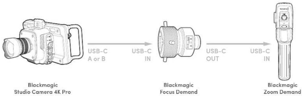
Takar noCleOBAteBbHOCTbNo3BOJAE TnIynpaBHeHNAKCECCyapAMNcNOB3OBaTBHa KaMepeToIbKO OINHpa3bEM USB,a BTOPOI npIMeHrTb IINBHeuHero HAKONITeJI. JnA 3TOrO OIN KoeU Ka6Ea USB-C HxKHO NODKIOUHTb K IIObOMy n3 nopTOB KaMepb(A nnB), aDpyroKoHeu-Ko BxOHDomy npTy yCTpoiCTBa FOkycupOBKn. BTOpbIM Ka6eIem coeHNHTe BixoH Ha Focus Demand co BxOdom Ha Zoom Demand.
KaebIb USB-C NmMeT MexaHn3M fKcauHn Ha KaKdOM KOHe nI npedotBpaueHn cnyaHoro oTOcoeHneHn. I M Heo6aTeIbHo NoIb3ObaTbc Bce BpeM, Ho OH IOne3eH npiaPabote B Ctydn, KOrda AkCEccyapbl NOCTOARHO NODKIOUeHbIKaMepe.

Akceccyapbl Blackmagic Focus Demand n Blackmagic Zoom Demand nO3B0NIOYUPaBnTb FOKycom N 3ymOM, He OTBOJ B3rJaD oT EKpaHa
Pa6ota c yctpoiCTBOM Blackmagic Focus Demand
B 3TOM pa3dene npnbedeHOn oNcHne fynKcui n pa3bEmOB yctpoiCTBa Blackmagic Focus Demand.
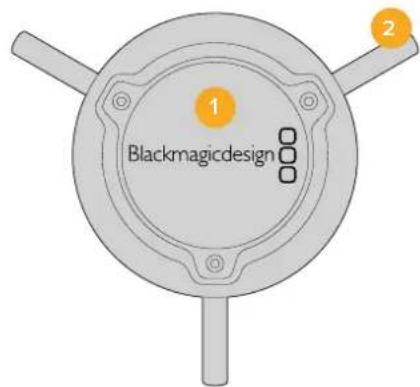
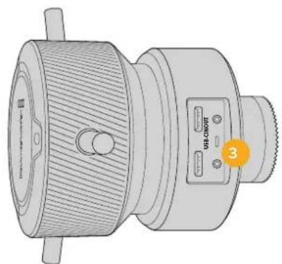
1 Puyka ynpablenia
YcHHeHne yBcTBNTeIbHOCTN
3a fynkun no3BOJRE BKNIOUATb DOONHITeBHOE ycINHe CnHa. Ha KaMepax Blackmagic Studio daHHa onu na NOO6Ha HAcTpoKe ISO. OHa none3Ha npi cBeMeke BycNOBx CnaBOro OCBeUeHn, YTObI KOMNEHCnPOBaTb HeOCTaTOHyIO EKcN03nIO uO6paXeHn IyBEInuHTb KOINueCTBO CBeta, NOnaHOwero Ha Matpnu. Jn 13meHn ETOrO napametpa INCNoJIb3yOTcJeBaI n PabBa CTpeKn B HAcTpoKe dB.
YcHHeMoKHO BkUOHTb BO BPem yIuHOn CbEMKn np3aKe coHua, YTO6bl doBtbc8oJIe BBICOKo JPKoCTn. CneJyET NOMHTb, 1TO NOBbIeHHa YBCTBNTelBHOCTb PnBODIT K NOBLeHIO Ha N3O6paXeHN MwMa.
YnpaBHeHne BbIepeKko
INHcTpymeHT ynpabIeHnB bIepKko HaxoITcM MeKdy CBeTOBbIM Kpyrom INHcTpymeHOM ynpabIeHnI dnaΦpaRMoyypOBHem cepHO.To6bl yMeHbIHTb nnYBEJIuHTb BblepKky, HabeIte yka3aTeIbMbIuHa NHdNkATOp BblepKkn, 3aTeM UeKNHTe Ha IeBOu NII npAOB CTpeKe. Ha KaMEpax Blackmagic Studio oHa npedctabIaET cOBo BblepKky 3aTbopa.
B clyuae MepuHna ee moXHo yMeHbUHTb. YMeHbUeHne BbIepKKn I03BOJAreT yBeInuHTb npkoCTb n3O6paXeHn 6e3 ycIIeHn CnHa,notomy TO B 3OM cLyuae BO3pactaet BpeM 3KcNo3uCn. YBeInuHne BbIepKKn BeTe K ChNXeHIO 3ΦeKta pa3MbIOCTN, BO3HkaIOSeTo pnp CbEme DINxUxxCsO6BeKTOB, N 6yET NOJIe3HO npn pa6oTe HAD dINHAMuHbIMn CuHeAMn.
BalaHc 6enoro
YcTaHOBt6balaHc6eNoRoMoXHoCnOMoUbIOCTpeNOK,HaxOJaUxXcnoObe CTOpOBHiOTINHdkaTOpauCBETOBOnTEMnePApTybl (pAOM CnHCTpyMeHTOM ynpabIeHnBaIDepKo).3aHaCTpoiKa NOMoRaET KoppeKtnPoBaTb 6aIaHC6eIOr B3aBNCIMOCTNOTICNOB3yEmbIXBaAHHbIMOMeHTNCTOuHKnOBOCBeueHn.
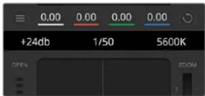
HabeintyekaataeMbIHN HnDnKaTOpbyCINHeN, BbIepKKn 6aHaHcBeno,3aTeM BbIbepnte HyXhBi eCTpeKn, YTO6blNMeHHTb HAcTpoiKN
O6paTnTE BHMaHHe,HTo NpeDnBnATb cam INndKAtOp CBetOBOro 6aHaHc He HyxHO.
I0 Mepe NepemseHn INndKaTopa NapamETpbI RGB Bn3y TAKKe 6ydyT MeHrTbc,
otpaxkA KoppeKTupOBky KaJdOro KaHaHa.
Haxmnte Ha KnaBnSy SHIFT n npotraHnte Kypoc B IIO6om Mecte ubetoboro kpyra
3TO DeIcTBn IocTbnt INHnKATOp ZBeTobO 6aHaHcBa TOnKy, rHe HaxoNTcYka3aTeB MbIu, YTO yCKOpIT npouecC pa60tbl.
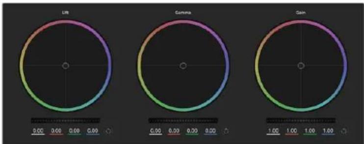
LBeTobBc Kpyrnn DnpaobtbcnapaemtpamnteHn, noIyToHa nCBeta Ha naHeHH LBeTOKoppeKun
IeKHTe KhONkO Mbln DbaXdb BHyTp nCBETOBORo Kpyra
3TO DeIcTBnE N03BONaTe C6pocuTb N3MeHEnHaCtpoek 6e3 IcNoJIb3OBAHnraIgABHOro peryJrTopa.
Haxmnte KhoNky c6poca, pacnoJoxeHHyO cnpaba ot zetoBoro kpyra
3TO NO3BOJAE TOMeHnB BCE PpebIyUne yCTaHOBKn UBeToboro 6aHaHca n COOTBEcTBYIOoero OoOero peryIaTopa.
06une perynTopbi
O6uIe peryIaTOpbl, pacnoJoxKeHHbIe noJcBeToBbIMKpyramN, no3BoJIoT 3aDaBaTb npametpbTeHn, noJyToHa nCBeta JnKaJdoRo KaHaJa npocTaPacHCTBa YRGB.
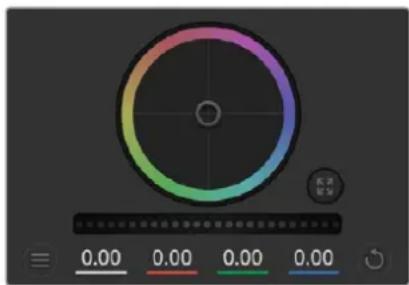
IIN3MeHnnaPametpoBnepeDnHbTe 06u npyTOp BnpaBO uN BcBO
Popraok pa6o8b1 c 60uM peryraTOpom
IpeepBnHbTe peryyTOp BnpaBO nn BneBO
Pn nepemeHn BBeO npoCoxOHT 3aTeMHeHne Bb6paHOro napameTp a npn DnHexHn BnPaBO 3OT npaMeTp cTAHOBntc CBeTnee. Pn BbIOJIHeHn IOo6HOro deCTBn OTo6paxaemble BHN3y npaMeTpbl YRGB 6dyt MeHrtbcra COOTBECTBYUOUM o6pa3OM.ДЯ nI3MeHEnr TOnbKO rPKOCTN (Y) nepeDINbTe peyIaTOp BBeBO nII BnpABo npn Haxatoi Knabuwe Alt nn Cmd. TaK kAn dJa CBETOKOPpeKUnn IcNoB3yETcR o6pa6OtKa YRGB, c NOMOUsbO tOJ onepaun M0XHO nOlyuHTb camble opunHaNbHbIe I3o6paKeHn. KopkeTnpOBka rPKOCTn daet HanluyuWne pe3yIbTaTbI, KORda INdikatop 6alaHcA rPKOCTn yCTaHOBLeH B npaBoe noLoxHne. B ATOM cLyue npimehenrEon 6pa6OtKa YRGB, B TO BPemk Ka npn LeBOM noLoXeHHn IcNoB3yETcTpaDInouHna O6pa6OtKa RGB. Ka npaBINO, 6OlbuHCTBO KOlonpNCtOB npednoHTaIOT nepBbI BapNaHT, Notomy UTO OH daet 6OlbWe BO3MOxHOCTe UnpaBHeHn CBeTOM. O6uaHACPoIka npaMeTp aCBeta npn 3TOM He 3ATpaINBaETc, NO3OMy Heo6XoIMMbI pe3yIbTa DOCTnraETc 6bICTpee.
Hactpoika KOhtpacta
3TOT INHCTpyMeHT N03BOJRAET UCTaHaBnBaT Dnana3OH MExdy cMoI TEMHO n CamoI CBETNO uACTbIO I3O6paXeHn. PpI erO nCNoJIb3OBaHN IOCTnRAeTCra TAKOI Je 3ΦΦeKT, KAK pN pa6ote C O6UIMN peryJrTOpAMn «TeHn» n «CBet», KOrDa C IX NOMOUIB BbINOJIHAIOT npOTINBOJNOLOXHbE KOPPEKTIPOBKn. No yMOJUaHNIU YCTaHOBNeHO 3NaueHne 50%. C nOMOUIb KOHTPOJIpe oCn, pacnoLOnxHe HcOTBeTcTByUOuNX ToeK MOxHO n3MeHnITb OTHCInTEbHO S-6Opa3HOb KnpIBoN. PpI pa6ote c LOG-daHHbIMN, KOTOpBIE NCNoJIb3yIOTc TExHONrIe NCBETOKODIPOBKn PANTORO NOKOEHn, NOCLe BbINOJIHENH NaCTPOIKn 6baHaCa 6eIoro n EKcNo3uINu peryINPobKa KOHTpacta n NOLOXeHn OTHCInTEbHO OCN MoKeT 3NaUInTebHO UnyuWntb pe3yIbTaT rpeDnHra.
Hactponka HacbiueHHoctn
C nomoou 3TOI INHCTpyMeHTa yBelenuBaHOT NIN yMeHbwaOT HacblueHHOCTb CbetaA Bn3o6paKeHH. IIO yMOnUaHHOyCTaHOBNeHO 3HaueHHe 50%.
Hacpoika toHa
3Ta HactpoiKa NOKa3bIaBcET BCE Bo3MOXHbIe TOHa NO nepIMeTpY cBeToboro Kpyra.
No ymoJUAHIO yCTaHOBJIeHO 3NaueHne 180 rpaDycOB, KOtOpoe Noka3bIbAet
mCXoHHe pacnPepdElenHne cBeTObBIX TOHO. YBeNueHne IIN yMeHbWeHne 3TOrO
3NaueHn IONBOJAE TEPEXODITK OTTEHKAM NO YacOBOn CTpeJIke IIN npOTNB Hee B
none pacnpedeHn ToHOB Ha cBeTobOM Kpyre.
HacpoiKa 6aHaHca npKocTn
Kamepbi Blackmagic Imeoi INCTpymentbI nepBnHoro rpeinHra ha ochobe DaVinci Resolve. Cntembl DaVinci nCnoNb3yOTcA c hauana 80-xrr.XX Beka, n Imehno nx caue BCero Bvibapot Kpyhble roJnBydckne CTydn dIra noctobpaOTkn CBOx fInlbMOB.
Takoi yHKUHOHnpeBpaaet Kamepbbl Blackmagic B MouHyToTexNky dnerpeweHn TBOpuecknx 3aau. Ondo n3 OTInuHTeNbHbix cepT ABnETCO6pa60ka YRGB.
Pn yctaHOBKe zBeta MoXHO Bb6paTb npoctpaHCTBO RGB nnn YRGB. KOnOpncbl npednoHTaOT nCNoIb3ObaTb YRGB,notOMy TTO B 3TOM cIyuee rpeiDnHr CTaHOBITcB 6oJee ToHHm IN NOBIIReTCB O3MOXHOCTb He3aBNCMmK KoppeKtnpOBKn KaHaIOB.
Ecn nIy INnkaTopa Bb6paHO KpaHHee npaBoe noLoXeHne, nCnoJb3yeTc 100% o6pa6Oka B YRGB. Ecn nIy HactpoKn 6alaHca npKocTn Bb6paHO KpaHHee neBoe noLoXeHne, nCnoJb3yETc 100% o6pa6Oka RGB. DnI aTOro npaMeTp a MoxHo yCTaHOBtB IIO6e 3NaueHne Mekdy npaBIM nLeBBIM noLoXeHnMn, uTo6bl nOlyntb n3O6paXeHne c Kom6Haune RGB n YRGB.
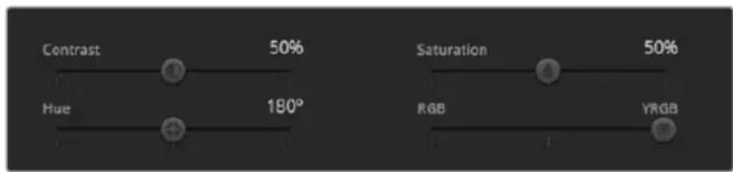
IJIINMHeHnKoHTpacta,HacbIeHHocn,OTtEHaNcApKocTnepeBnHbTe CnAepbl BnpaBO NnBnEBo
Tak Ka rpeiINr RnreTcA 6COIIOTH TBOpueckm npoceccOM, BbI6p ToH INHO HAcToK NnHOCTbO 3ABNCIT OT ppeNoTeHn NOB3OBaTeIa.
CnHxpoHn3aunHaCTpoek
Pn noKJIoueHn KaMepbl Blackmag K BnDEOMKUepy OHa noLyaaet CnHaIbI ynpabLeHn c ATEM. Ecnn KTO-To cnUaHNo n3MeHn HacTpOuKn Ha cAmo KaMepe, OHb6yT OTMeHbI B aBtOMaTnueckom pexmE dJa CObIoJeHn CnHXPOHN3aun.
Developer Information
Blackmagic SDI Camera Control Protocol
Version 1.5
If you are a software developer you can use the Blackmagic SDI to construct devices that integrate with our products. Here at Blackmagic Design, our approach is to open up our protocols and we eagerly look forward to seeing what you come up with!
Overview
This document describes an extensible protocol for sending a unidirectional stream of small control messages embedded in the non-active picture region of a digital video stream. The video stream containing the protocol stream may be broadcast to a number of devices. Device addressing is used to allow the sender to specify which device each message is directed to.
Assumptions
Alignment and padding constraints are explicitly described in the protocol document. Bit fields are packed from LSB first. Message groups, individual messages and command headers are defined as, and can be assumed to be, 32 bit aligned.
Blanking Encoding
A message group is encoded into a SMPTE 291M packet with DID/SDID x51/x53 in the active region of VANC line 16.
Message Grouping
Up to 32 messages may be concatenated and transmitted in one blanking packet up to a maximum of 255 bytes payload. Under most circumstances, this should allow all messages to be sent with a maximum of one frame latency.
If the transmitting device queues more bytes of message packets than can be sent in a single frame, it should use heuristics to determine which packets to prioritize and send immediately. Lower priority messages can be delayed to later frames, or dropped entirely as appropriate.
Abstract Message Packet Format
Every message packet consists of a three byte header followed by an optional variable length data block. The maximum packet size is 64 bytes.
| Destination device (uint8) | Device addresses are represented as an 8 bit unsigned integer. Individual devices are numbered 0 through 254 with the value 255 reserved to indicate a broadcast message to all devices. |
| Command length (uint8) | The command length is an 8 bit unsigned integer which specifies the length of the included command data. The length does NOT include the length of the header or any trailing padding bytes. |
| Command id (uint8) | The command id is an 8 bit unsigned integer which indicates the message type being sent. Receiving devices should ignore any commands that they do not understand. Commands 0 through 127 are reserved for commands that apply to multiple types of devices. Commands 128 through 255 are device specific. |
| Reserved (uint8) | This byte is reserved for alignment and expansion purposes. It should be set to zero. |
| Command data (uint8[]) | The command data may contain between 0 and 60 bytes of data. The format of the data section is defined by the command itself. |
| Padding (uint8[]) | Messages must be padded up to a 32 bit boundary with 0x0 bytes. Any padding bytes are NOT included in the command length. |
Receiving devices should use the destination device address and or the command identifier to determine which messages to process. The receiver should use the command length to skip irrelevant or unknown commands and should be careful to skip the implicit padding as well.
Defined Commands
Command 0 : change configuration
| Category (uint8) | The category number specifies one of up to 256 configuration categories available on the device. |
| Parameter (uint8) | The parameter number specifies one of 256 potential configuration parameters available on the device. Parameters 0 through 127 are device specific parameters. Parameters 128 though 255 are reserved for parameters that apply to multiple types of devices. |
| Data type (uint8) | The data type specifies the type of the remaining data. The packet length is used to determine the number of elements in the message. Each message must contain an integral number of data elements. |
| Currently defined values are: | |
| 0: void / boolean | A void value is represented as a boolean array of length zero. The data field is a 8 bit value with 0 meaning false and all other values meaning true. |
| 1: signed byte Data elements are signed bytes | |
| 2: signed 16 bit integer Data elements are signed 16 bit values | |
| 3: signed 32 bit integer Data elements are signed 32 bit values | |
| 4: signed 64 bit integer Data elements are signed 64 bit values | |
| 5: UTF-8 string Data elements represent a UTF-8 string with no terminating character. | |
Data types 6 through 127 are reserved.
| 128: signed 5.11 fixed point | Data elements are signed 16 bit integers representing a real number with 5 bits for the integer component and 11 bits for the fractional component. The fixed point representation is equal to the real value multiplied by 2^11. The representable range is from -16.0 to 15.9995 (15 + 2047/2048). |
Data types 129 through 255 are available for device specific purposes.
| Operation type (uint8) | The operation type specifies what action to perform on the specified parameter. Currently defined values are: |
| 0: assign value | The supplied values are assigned to the specified parameter. Each element will be clamped according to its valid range. A void parameter may only be 'assigned' an empty list of boolean type. This operation will trigger the action associated with that parameter. A boolean value may be assigned the value zero for false, and any other value for true. |
| 1: offset / toggle value | Each value specifies signed offsets of the same type to be added to the current parameter values. The resulting parameter value will be clamped according to their valid range. It is not valid to apply an offset to a void value. Applying any offset other than zero to a boolean value will invert that value. |
Operation types 2 through 127 are reserved.
| Operation types 128 through 255 are available for device specific purposes. | |
| Data (void) | The data field is 0 or more bytes as determined by the data type and number of elements. |
The category, parameter, data type and operation type partition a 24 bit operation space.
| Group | ID | Parameter | Type | Index | Minimum | Maximum | Interpretation |
| Lens | 0.0 | Focus | fixed16 | - | 0.0 | 1.0 | \( 0.0 = \text {near,}1.0 = \text {far} \) |
| 0.1 | Instantaneous autofocus | void | - | - | - | trigger instantaneous autofocus | |
| 0.2 | Aperture (f-stop) | fixed16 | - | -1.0 | 16.0 | Aperture Value (where fnumber \( = \text {sqrt(2^AV)} \)) | |
| 0.3 | Aperture (normalised) | fixed16 | - | 0.0 | 1.0 | \( 0.0 = \text {smallest,}1.0 = \text {largest} \) | |
| 0.4 | Aperture (ordinal) | int16 | - | 0 | n | Steps through available aperture values from minimum (0) to maximum (n) | |
| 0.5 | Instantaneous auto aperture | void | -- - | - | trigger instantaneous auto aperture | ||
| 0.6 | Optical image stabilisation | boolean | - | - | - | true = enabled, false = disabled | |
| 0.7 | Set absolute zoom (mm) | int16 | - | 0 | max | Move to specified focal length in mm, from minimum (0) to maximum (max) | |
| 0.8 | Set absolute zoom (normalized) | fixed16 - 0.0 | 1.0 | Move to specified focal length: \( 0.0 = \text {wide,}1.0 = \text {tele} \) | |||
| 0.9 | Set continuous zoom (speed) | fixed16 - -1.0 | +1.0 | Start/stop zooming at specified rate: -1.0 = zoom wider fast, 0.0 = stop, +1 = zoom tele fast | |||
| Video | 1.0 Video mode int8 | [0] = frame rate -- | fps as integer(eg 24, 25, 30, 50, 60) | ||||
| [1] = M-rate -- 0 = regular, 1 = M-rate | |||||||
| [2] = dimensions -- | 0 = NTSC, 1 = PAL, 2 = 720,3 = 1080, 4 = 2kDCI, 5 = 2k16:9,6 = UHD, 7 = 3k Anamorphic,8 = 4k DCI, 9 = 4k 16:9,10 = 4.6k 2.4:1, 11 = 4.6k | ||||||
| [3] = interlaced -- | 0 = progressive,1 = interlaced | ||||||
| [4] = Color space | -- 0 = YUV | ||||||
| 1.1 | Gain (up to Camera 4.9) | int8 | 1 | 128 | 1x, 2x, 4x, 8x, 16x, 32x, 64x, 128x gain | ||
| 1.2 | Manual White Balance | int16 | [0] = color temp | 2500 | 10000 | Color temperature in K | |
| int16 | [1] = tint | -50 | 50 | tint | |||
| 1.3 | Set auto WB | void | - | - | - | Calculate and set auto white balance | |
| 1.4 | Restore auto WB | void | - | - | - | Use latest auto white balance setting | |
| 1.5 | Exposure (us) | int32 | 1 | 42000 | time in us | ||
| 1.6 | Exposure (ordinal) | int16 | - | 0 | n | Steps through availableexposure values from minimum(0) to maximum (n) | |
| 1.7 | Dynamic Range Mode | int8 enum | - | 0 | 2 | 0 = film, 1 = video,2 = extended video | |
| 1.8 | Video sharpening level | int8 enum | - | 0 | 3 | 0 = off, 1 = low, 2 = medium,3 = high | |
| 1.9 Recording format | int16 | [0] = file frame rate | -- | fps as integer(eg 24, 25, 30, 50, 60, 120) | |||
| [1] = sensor frame rate | - | - | fps as integer, valid whensensor-off-speed set (eg 24,25, 30, 33, 48, 50, 60, 120),no change will be performed ifthis value is set to 0 | ||||
| [2] = frame width | -- in pixels | ||||||
| [3] = frame height | -- in pixels | ||||||
| [4] = flags | -- [0] = file-M-rate | ||||||
| - | - | [1] = sensor-M-rate, validwhen sensor-off-speed-set | |||||
| -- [2] = sensor-off-speed | |||||||
| -- [3] = interlaced | |||||||
| -- [4] = windowed mode | |||||||
| 1.10 | Set auto exposure mode | int8 | - | 0 | 4 | 0 = Manual Trigger, 1 = Iris,2 = Shutter, 3 = Iris + Shutter,4 = Shutter + Iris | |
| 1.11 | Shutter angle | int32 | - | 100 | 36000 | Shutter angle in degrees,multiplied by 100 | |
| 1.12 | Shutter speed | int32 | - | Currentsensorframe rate | 5000 | Shutter speed value as a fraction of 1, so 50 for 1/50th of a second | |
| 1.13 | Gain | int8 | - | -128 | 127 | Gain in decibel (dB) | |
| 1.14 | ISO | int32 | - | 0 | 2147483647 | ISO value | |
| 1.15 | Display LUT | int8 | [0] = selected LUT | -- | 0 = None, 1 = Custom,2 = film to video,3 = film to extended video | ||
| [1] = enabled or not | -- 0 = Not enabled, 1 = Enabled | ||||||
| 1.16 | ND Filter | fixed16 | [0] = stops | 0.0 | 16.0 | f-stop of ND filter to use | |
| Audio | 2.1 | Headphone level | fixed16 | - | 0.1 | 1.0 | 0.0 = minimum, 1.0 = maximum |
| 2.2 | Headphone program mix | fixed16 | - | 0.1 | 1.0 | 0.0 = minimum, 1.0 = maximum | |
| 2.3 | Speaker level | fixed16 | - | 0.1 | 1.0 | 0.0 = minimum, 1.0 = maximum | |
| 2.4 | Input type | int8 | - | 0 | 3 | 0 = internal mic,1 = line level input,2 = low mic level input,3 = high mic level input | |
| 2.5 Input levels fixed16 | [0] ch0 | 0.0 | 1.0 | 0.0 = minimum, 1.0 = maximum | |||
| [1] ch1 | 0.0 | 1.0 | 0.0 = minimum, 1.0 = maximum | ||||
| 2.6 | Phantom power | boolean | - | - | - | true = powered,false = not powered | |
| Output | 3.0 Overlay enables | uint16bit field | -- - | bit flags:[0] = display status,[1] = display frame guidesSome cameras don't allow separate control of frameguides and status overlays. | |||
| 3.1 | Frame guides style (Camera3.x) | int8 | -0 8 | 0 = HDTV, 1 = 4:3, 2 = 2:4:1,3 = 2.39:1, 4 = 2.35:1,5 = 1.85:1, 6 = thirds | |||
| 3.2 | Frame guides opacity(Camera 3.x) | fixed16 | - | 0.1 | 1.0 | 0.0 = transparent, 1.0 = opaque | |
| 3.3 | Overlays(replaces .1 and .2above fromCameras 4.0) | int8 | [0] = frame guidesstyle | - | - | 0 = off, 1 = 2.4:1, 2 = 2.39:1,3 = 2.35:1, 4 = 1.85:1, 5 = 16:9,6 = 14:9, 7 = 4:3, 8 = 2:1,9 = 4:5, 10 = 1:1 | |
| [1] = frame guide opacity | 0 | 100 | 0 = transparent, 100 = opaque | ||||
| [2] = safe area percentage | 0 | 100 | percentage of full frameused by safe area guide(0 means off) | ||||
| [3] = grid style | - | - | bit flags:[0] = display thirds,[1] = display cross hairs,[2] = display center dot,[3] = display horizon | ||||
| Display | 4.0 | Brightness | fixed16 | - | 0.0 | 1.0 | 0.0 = minimum, 1.0 = maximum |
| 4.1 Exposure and focus tools | int16bit field | 0x1 = zebra,0x2 = focus assist,0x4 = false color | - | - | 0 = disable, 1 = enable | ||
| 4.2 | Zebra level | fixed16 | - | 0.0 | 1.0 | 0.0 = minimum, 1.0 = maximum | |
| 4.3 | Peaking level | fixed16 | - | 0.0 | 1.0 | 0.0 = minimum, 1.0 = maximum | |
| 4.4 | Color bar enable | int8 | - | 0 | 30 | 0 = disable bars,1-30 = enable bars with timeout(seconds) | |
| 4.5 Focus Assist | int8 | [0] = focus assist method | - | - | 0 = Peak,1 = Colored lines | ||
| [1] = focus line color | - | - | 0 = Red,1 = Green,2 = Blue,3 = White,4 = Black | ||||
| 4.6 | Program return feed enable | int8 | - | 0 | 30 | 0 = disable, 1-30 = enable withtimeout (seconds) | |
| Tally | 5.0 | Tally brightness | fixed16 | - | 0.0 | 1.0 | Sets the tally front and tally rear brightness to the same level. 0.0 = minimum, 1.0 = maximum |
| 5.1 | Front tally brightness | fixed16 | - | 0.0 | 1.0 | Sets the tally front brightness. 0.0 = minimum, 1.0 = maximum | |
| 5.2 | Rear tally brightness | fixed16 | - | 0.0 | 1.0 | Sets the tally rear brightness. 0.0 = minimum, 1.0 = maximum Tally rear brightness cannot be turned off | |
| Reference | 6.0 | Source | int8 enum | - | 0 | 2 | 0 = internal, 1 = program, 2 = external |
| 6.1 | Offset | int32 | - | - | - | +/- offset in pixels | |
| Confi-guration | 7.0 Real Time Clock | int32 | [0] time | - | - | - | BCD - HHMMSSFF (UCT) |
| [1] date | - | - | - | BCD - YYYYYMMDD | |||
| 7.1 | System language | string | [0-1] | - | - | ISO-639-1 two character language code | |
| 7.2 | Timezone | int32 | - | - | - | Minutes offset from UTC | |
| 7.3 | Location | int64 | [0] latitude | - | - | BCD - sDDDdddddddddddd where s is the sign: 0 = north (+), 1 = south (-); DD degrees, ddddddddddd decimal degrees | |
| [1] longitude | - | - | BCD - sDDDdddddddddddd where s is the sign: 0 = west (-), 1 = east (+); DDD degrees, ddddddddddd decimal degrees | ||||
| Color Correction | 8.0 Lift Adjust fixed16 | [0] red -2.0 2.0 default | 0.0 | ||||
| [1] green -2.0 2.0 default | 0.0 | ||||||
| [2] blue -2.0 2.0 default | 0.0 | ||||||
| [3] luma -2.0 2.0 default | 0.0 | ||||||
| 8.1 | Gamma Adjust | fixed16 | [0] red -4.0 | 4.0 default 0.0 | |||
| [1] green -4.0 | 4.0 default 0.0 | ||||||
| [2] blue -4.0 | 4.0 default 0.0 | ||||||
| [3] luma -4.0 | 4.0 default 0.0 | ||||||
| 8.2 | Gain Adjust | fixed16 | [0] red 0.0 | 16.0 | default 1.0 | ||
| [1] green 0.0 | 16.0 | default 1.0 | |||||
| [2] blue 0.0 | 16.0 | default 1.0 | |||||
| [3] luma 0.0 | 16.0 | default 1.0 | |||||
| 8.3 Offset Adjust | fixed16 | [0] red -8.0 | 8.0 | default 0.0 | |||
| [1] green -8.0 | 8.0 | default 0.0 | |||||
| [2] blue -8.0 | 8.0 | default 0.0 | |||||
| [3] luma -8.0 | 8.0 | default 0.0 | |||||
| 8.4 | Contrast Adjust fixed16 | [0] pivot | 0.0 | 1.0 | default 0.5 | ||
| [1] adj | 0.0 | 2.0 | default 1.0 | ||||
| 8.5 | Luma mix | fixed16 | - | 0.0 | 1.0 | default 1.0 | |
| 8.6 Color Adjust | fixed16 | [0] hue | -1.0 | 1.0 | default 0.0 | ||
| [1] sat | 0.0 | 2.0 | default 1.0 | ||||
| 8.7 | Correction Reset Default | void | - | - | - | reset to defaults | |
| Media | 10.0 | Codec int8 enum | [0] = basic codec -- | 0 = Cinema/DNG, 1 = DNxHD, 2 = ProRes, 3 = Blackmagic RAW | |||
| [1] = code variant | - | - | Cinema/DNG: 0 = uncompressed, 1 = lossy 3:1, 2 = lossy 4:1 | ||||
| - | - | ProRes: 0 = HQ, 1 = 422, 2 = LT, 3 = Proxy, 4 = 444, 5 = 444XQ | |||||
| - | - | Blackmagic RAW: 0 = Q0, 1 = Q5, 2 = 3:1, 3 = 5:1, 4 = 8:1, 5 = 12:1 | |||||
| 10.1 | Transport mode int8 | [0] = mode | -- | 0 = Preview, 1 = Play, 2 = Record | |||
| [1] = speed | -- | -ve = multiple speeds backwards, 0 = pause, +ve = multiple speeds forwards | |||||
| [2] = flags | -- | 1<<0 = loop, 1<<1 = play all, 1<<5 = disk1 active, 1<<6 = disk2 active, 1<<7 = time-lapse recording | |||||
| [3] = slot 1 storage medium | - | - | 0 = CFast card, 1 = SD Card, 2 = SSD Recorder, 3 = USB | ||||
| [4] = slot 2 storage medium | - | - | 0 = CFast card, 1 = SD Card, 2 = SSD Recorder, 3 = USB | ||||
| 10.2 | Playback Control | int8 enum | [0] = clip | - | - | 0 = Previous, 1 = Next | |
| 10.3 | Still Capture | void | - | - | - | Capture | |
| PTZ Control | 11.0 | Pan/Tilt Velocity | fixed16 | [0] = pan velocity -1.0 | 1.0 | -1.0 = full speed left, 1.0 = full speed right | |
| [1] = tilt velocity | -1.0 | 1.0 | -1.0 = full speed down, 1.0 = full speed up | ||||
| 11.1 | Memory Preset | int8 enum | [0] = preset command | - | - | 0 = reset, 1 = store location, 2 = recall location | |
| int8 | [1] = preset slot | 0.5- | |||||
| Metadata | 12.0 | Reel | int16 | [0] = reel | 0 | 999 | - |
| 12.1 Scene Tags | signedbyte | [0] = scene tags | -- | -1 = None0 = WS1 = CU2 = MS3 = BCU4 = MCU5 = ECU | |||
| [1] = interior /exterior | - | - | 0 = Exterior1 = Interior | ||||
| [2] = day / night | -- | 0 = Night1 = Day | |||||
| 12.2 | Scene | string | [0-4] = scene | - | - | - | |
| 12.3 | Take | signedbyte | [0] = take number | 1 | 99 | - | |
| [1] = take tags | -- | 1 = None0 = PU1 = VFX2 = SER | |||||
| 12.4 | Good Take | void | [0] = good take | - | - | - | |
| 12.5 | Camera ID | string | [0-28] = ID | - | - | - | |
| 12.6 | Camera Operator | string | [0-28] = operator | - | - | - | |
| 12.7 | Director | string | [0-27] = director | - | - | - | |
| 12.8 | Project Name | string | [0-28] = project | - | - | - | |
| 12.9 | Lens Type | string | [0-55] = type | - | - | - | |
| 12.10 | Lens Iris | string | [0-19] = iris | - | - | - | |
| 12.11 | Lens Focal Length | string | [0-29] = focal length | - | - | - | |
| 12.12 | Lens Distance | string | [0-49] = distance | - | - | - | |
| 12.13 | Lens Filter | string | [0-29] = filter | - | - | - | |
| 12.14 | Slate Mode | signedbyte | [0] = type | -- | 0 = Recording1 = Playback | ||
| 12.15 | Slate Target | string | [0-31] = name | - | - | - | |
Example Protocol Packets
| Operation | Packet Length Byte | ||||||||||||||||
| 0 | 1 | 2 | 3 | 4 | 5 | 6 | 7 | 8 | 9 | 10 | 11 | 12 | 13 | 14 | 15 | ||
| header command data | |||||||||||||||||
| destination | length | command | reserved | category | parameter | type | operation | ||||||||||
| trigger instantaneous auto focus on camera 4 | 844000100 | ||||||||||||||||
| turn on OIS on all cameras 12 | 25550006001000 | ||||||||||||||||
| set exposure to 10 ms on camera 4 (10 ms = 10000 us = 0x00002710) | 12 | 4 | 8 | 0 | 0 | 1 | 5 | 3 | 0 | 0x10 | 0x27 | 0x00 | 0x00 | ||||
| add 15% to zebra level (15 % = 0.15 f = 0x0133 fp) | 12 | 4 | 6 | 0 | 0 | 4 | 2 | 128 | 1 | 0x33 | 0x01 | 0 | 0 | ||||
| select 1080p 23.98 mode on all cameras | 16 | 255 | 9 | 0 | 0 | 1 | 0 | 1 | 0 | 24 | 1 | 3 | 0 | 0 | 0 | 0 | 0 |
| subtract 0.3 from gamma adjust for green & blue (-0.3 ^=0xff9a fp) | 16 | 4 | 12 | 0 | 0 | 8 | 1 | 128 | 1 | 0 | 0 | 0x9a | 0xffd | 0x9a | 0xffd | 0 | 0 |
| all operations combined | 76 | 44000100 | |||||||||||||||
| 1 | 0 | 0 | 0 | 4 | 8 | 0 | 0 | 1 | 5 | 3 | 0 | 0x10 | 0x27 | 0x00 | 0x00 | ||
| 4 | 6 | 0 | 0 | 4 | 2 | 128 | 1 | 0x33 | 0x01 | 0 | 0 | 255 | 9 | 0 | 0 | ||
| 1 | 0 | 1 | 0 | 24 | 1 | 3 | 0 | 0 | 0 | 0 | 0 | 4 | 12 | 0 | 0 | ||
| 8 | 1 | 128 | 1 | 0 | 0 | 0x9a | 0xffd | 0x9a | 0xffd | 0 | 0 | ||||||
Blackmagic Embedded Tally Control Protocol
Version 1.0 (30/04/10)
This section is for third party developers or anybody who may wish to add support for the Blackmagic Embedded Tally Control Protocol to their products or system. It describes the protocol for sending tally information embedded in the non-active picture region of a digital video stream.
Data Flow
A master device such as a broadcast switcher embeds tally information into its program feed which is broadcast to a number of slave devices such as cameras or camera controllers. The output from the slave devices is typically fed back to the master device, but may also be sent to a video monitor.
The primary flow of tally information is from the master device to the slaves. Each slave device may use its device id to extract and display the relevant tally information.
Slave devices pass through the tally packet on their output and update the monitor tally status, so that monitor devices connected to that individual output may display tally status without knowledge of the device id they are monitoring.
Assumptions
Any data alignment / padding is explicit in the protocol. Bit fields are packed from LSB first.
Blanking Encoding
One tally control packet may be sent per video frame. Packets are encoded as a SMPTE 291M packet with DID/SDID x51/x52 in the active region of VANC line 15. A tally control packet may contain up to 256 bytes of tally information.
Packet Format
Each tally status consists of 4 bits of information:
uint4
bit 0: program tally status (0=off, 1=on)
bit 1: preview tally status (0=off, 1=on)
bit 2-3: reserved (0x0)
The first byte of the tally packet contains the monitor device tally status and a version number.
Subsequent bytes of the tally packet contain tally status for pairs of slave devices. The master device sends tally status for the number of devices configured/supported, up to a maximum of 510.
struct tally
uint8
bit 0: monitor device program tally status (0=off, 1=on)
bit 1: monitor device preview tally status (0=off, 1=on)
bit 2-3: reserved (0b00)
bit 4-7: protocol version (0b0000)
uint8[0]
bit 0: slave device 1 program tally status (0=off, 1=on)
bit 1: slave device 1 device preview tally status (0=off, 1=on)
bit 2-3: reserved (0b00)
bit 4: slave device 2 program tally status (0=off, 1=on)
bit 5: slave device 2 preview tally status (0=off, 1=on)
bit 6-7: reserved (0b00)
uint8[1]
bit 0: slave device 3 program tally status (0=off, 1=on)
bit 1: slave device 3 device preview tally status (0=off, 1=on)
bit 2-3: reserved (0b00)
bit 4: slave device 4 program tally status (0=off, 1=on)
bit 5: slave device 4 preview tally status (0=off, 1=on)
bit 6-7: reserved (0b00)
中
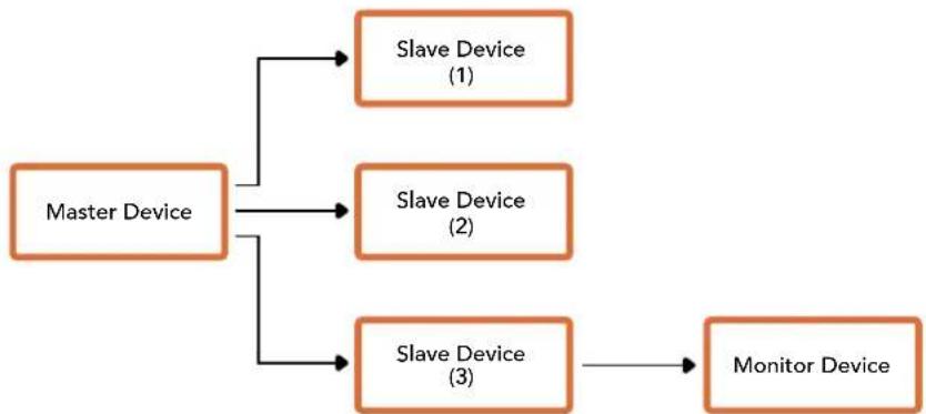
| Byte 7 | MSB 6 5 4 | 3 | 2 | 1 | 0 LSB | |||||
| 0 | Version(Ob0) | Version(Ob0) | Version(Ob0) | Version(Ob0) | Reserved(Ob0) | Reserved(Ob0) | MonitorPreview | MonitorProgram | ||
| 1 | Reserved(Ob0) | Reserved(Ob0) | Slave1Preview | Slave1Program | Reserved(Ob0) | Reserved(Ob0) | Slave0Preview | Slave0Program | ||
| 2 | Reserved(Ob0) | Reserved(Ob0) | Slave3Preview | Slave3Program | Reserved(Ob0) | Reserved(Ob0) | Slave2Preview | Slave2Program | ||
| 3 | ... | |||||||||
Передача Tally-cигналов с помоцью мodylaws Blackmagic 3G-SDI Shield for Arduino
EcnBbI nCnoJIb3yete He ATEM, a pyroJSDI-BuJeomKUep, Blackmagic Studio Camera BCE paBHO MoXeT noDpeKINBaT bHnIkaIIO COCTOHN. YTo6bl Ha KaMepy noCTynaI o6paTHbI npOrpaMMhB cnHaI, ee HxNHO CoeINHtB c Tally-BbIXoOM BUneOMKUepa Uepe3 MoDyIb Blackmagic 3G-SDI Shield for Arduino.
IapannelbHbTally-noprBnueomKwepaNockluohOT K KOHTaTAM D2-D9 moyla Blackmagic, a SDI-BbIXoMDmoyncoeHHOT CO BcEMN kamepaMn Blackmagic uepe3 ycInTeB-pacnpedeJIteB, Hanpimep Blackmagic Mini Converter SDI Distribution. Takm cnocobm CngHaBnHnkauncoCTOHNMOxHO nepeDaBaTb Ha BOCemb OTdeNbHbX kaMeP.
Homepa kamepbbl Blackmagic n Tally-BbixoDa Bndeomikwepa doJnxhbl coBnaad. Jnra 3toro Moxet notpe60BaTbcra noIb3ObaTeIbckn nepexoDnK co6ctBeHHoro n3rotobHeHr. Ero KOHTAKT GND huxho coeinnb c KOHTAKTOM GND ha moDyne Blackmagic 3G-SDI Shield.
В tabице Нжке nokazaho, кak Homepa kamep Blackmagic Tally-вixodв bindeomiksepa Должны COOTBETCTBOBaTkoHTaTm Ha moyne Blackmagic 3G-SDI Shield for Arduino.
| Homep Камерbl Blackmagic | Homep Вхoda на Видаомпшеpe | Контakt на Arduino |
| 11 D2 | ||
| 2 2 D3 | ||
| 3 3 D4 | ||
| 4 4 D5 | ||
| 5 5 D6 | ||
| 6 6 D7 | ||
| 7 7 D8 | ||
| 8 8 D9 |
B 3TOM pa3dJeI npINBOIDTCr npIMep KOMaHd, C nMOObIIO KOtOpbIX MoyIb Blackmagic 3G-SDI Shield for Arduino HaprabJET Tally-cnHaN Ha KaMepy, KOrda ee I3o6paxeHne cTaHOBITc nporpaMMbIM. Bce SDI-BnDEoMnKwepbl, IMeIOUHe BbIXObl C OTKpbITbIM KOJIeKTopOM, MoXHO hAcTpoNTb IaI nepeDaunTaknx CnHaNOB uepe3 MoyIb Blackmagic 3G-SDI Shield for Arduino. PkyoBOcTBo DoCTyHNO B ceHTpe NoDaePxxN Ha Be6-caTe Blackmagic Design no aDpecy www.blackmagicdesign.com/ru/support.
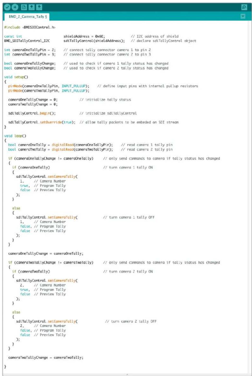
PpIeep KOMaH, c nOoBIO KoTOpbX Moynb Blackmigic 3G-SDI Shield for Arduino o6hApyKnaeT Hauuue Tally-cnHaNoB dnn BxOob 1 2 n npocdaet nx cepes cboi SDI-Bbixod. Ha cootbcctByioe kAmpe npn ATom 3aRaopaetc nnDnKaTOp coCToHn.
Pomoucb
Kak noyuHTb nOmoa
Cambib 6bictpbin cnoocob noyuntb nomoosb - o6paTntbcra K ctpaHnca m npdepeKn Ha caTe Blackmagic Design n npoBepntb hainue nocleDnHex cnpaBOOHybx MaTePnaOB no kamepe.
Pazel noDiepKn Ha caTe Blackmagic Design
IocneHHe Bepn pyKOBODCTBa No ekCnnyatau, nporpaMMHO oBeceueHn IdoonHteBHyIO nHOpMaUIO moXHo hAHTN B pa3dene noDpejKKn Blackmagic Design Ha cTpaHnce www.blackmagicdesign.com/ru/support.
COOTBETCTBNE Tpe6oBaHnIaM ISED (KaHaDa)
Данhoe obopydOBaHne COOTBETCTByeT KaHaIckIM cTaHApTaM ДЯ сФpoBbIX yctpoiCTB KlnaccA A.
IIO6aMoNΦKauHnNnNCnoB3ObaHne N3dennHe No Ha3HaueHNO MOryT NOBneCy 3a co6o anHnyinpoBaHne 3aBHe HnO COOTBeTCTBNN 3TmCtAHapTaM.
IOnKIOUeHne K HDMI-INHTepFeey DOJXHO BbINONHrTcR C NOMOUIKaueCTBeHHoro 3kpaHnpoBaHHoro Ka6en.
AnHoe o6OpOBOAHne npoTeCTnPOBAHO NO Tpe6OBaHNm, npeBraBnREMbIM K yctpOcTBam npn pa6ote B HexInbIX NOMeueHnx. Ppi NcNoIb3OBaHN B 6bITOBbIX ycIOBnIX OHO MOKeT CTaHOBnTbcr NCTOCHNKOM NOMex dJa paNOCuRHaHa.
ПразвILA 6e3oNaChoctn
Eknnnyataa Kamepbbl Blackmagc Studio donyckaetc B ycnobnx Tponueckoro knmata c temnepatypookpykaoue npde do 40^
BHytpn Kopnyca He coedepekxatc Teta, noIeXaune 06cnykBaHIO.
Iy BbInOnHeHHpeMOHTbIX pa6OT o6paTntecb B MeCThbl CepBnchbl ueHTp Blackmagic Design.
Kamepa n akkymyIaTOp He doJxHbI noBepraTbc npoJOnKuTeNbHOMy BO3dEiCTBnIO pRmblx coNHeuHbIX lyuei, a IITn-NOHHbIe 6aTaPei cneDyET XpaHHTb BdaII NTocUHKnOB TeIIa.

Pn pa6ote c npnilaraembIM cTeEBIM aanTepom donyckaetcA KcnnyataunB MeCTax He Bblwe 2000 metpoB Hnd ypOBHem MOpJ.
YBeDOMJIeHne dIg KHTeJIe WITATA KaIINΦOpHN
Pp pa6oTe c 3Tm o6OpyOBAHnem cyueCTByeT BO3MOxHOCTb KOHTaTa C coepkaunmcB nIaaTmacce MkpoPnmeCM MHOrO6pOMcTOr O6npeHna, KOtOpBIB Wtate KaIINΦopHnI npu3HaH kaIeporeHOM uYBeJIuHBaET pCK BPOXdHHbIX deEeKToB IN nopOKOB peIPOdyKTINBHOn CNTeMbI.
Iopno6Hee cm. HOpMaunu Ha caTe www.P65Warnings.ca.gov.
Гаразня
OrpaHnueHHa rapaHTna cpoKOM 12 mecaeB
KomnaHnA Blackmagic Design rapaHTnpyET OTCytBVe B daHHOM n3delenn DeefekTOB Maepnana I npOn3BOcTBeHHoro 6paka B TeueHne 12 MeecaeB C dAtb IpodaJN. Ecn Bo BpeMraPANTnHO rpoKa 6yDyT BByBHeHb Deefektb, Blackmagic Design no cBoemy yCMOTpeHnIO BInONHIT pEmOH HeNCnPabHoro n3delenn 6e3 OnLaTbI CTouMoCTn 3aNaCTe N TpyDo3aTpA INI 3aMeHNT TaKoe n3delenne HObIM.
YTo6bI BocnoB3OBA tbc Hactoae rapaHTne, noTpe6nte b683aH yBeDMtB kOMnAHIo Blackmagic Design o defeke Tdo OKOHuaHra rapaHTnHorO cPoka n obecneuHtB ycIOBnI dI npedoctabHeHr Heo6xodmbix ycnyr. NpTe6nte hceT OTBeTCTBeHHocTb 3a yNakOBky IocTabKy HeNCnPABHO r3dEINBa CootBeTCTByUOni cepBnCHbI ceHtp Blackmagic Design C ONlatoN OTOBbIX pAcXODOB. NpTe6nte b683aH onLAtNb BCE paCxOdbI no DoctabKe i CTpaXOBAHIO, IOJINHBI, HANOrn INHbIe C6Opbl B CB83n C BO3BpaTom N3dEJIy BHe 3aBVCIMOCTN OT npUHNbI BO3Bpata.
Hactoa rapaHTn He pacnpocpaHaeTc Ha deFeKbI, OTKa3bI NOBpeXdHnB3NJI HEnpABINbHO yXOda IIN
0b3NkUe n3-3a HeHaJnxJrOncNoB3OBAHn, HnPaBnBHO yXOda IIN
0bCnyKuBaHn. KomnaHra Blackmag Design He o63aHa npedocabTb ycLytn no
Hactoaer rapaHTn: a) dIy UcTaPHeHHnOBpeXdHn, Bo3NkUnx B pe3yIbTaTe DeCTBn
no yCTAHOBke, pEmOHTy IIN o6CnyKuBaHnIO 3deLnn LInam, KOTOpBe He ABnIoTc
nepcoHaIOM Blackmagic Design; 6) dIry uCtpaHHeHHnOBpeXdHn, Bo3NkUnx B pe3yIbTaTe
HeHaJnxJrOncNoB3OBAHnI INI NOKIIouHeHHN K HecOBmecTMOMy o6OpdyoBaHnIO;
B) dIy UcTaPHeHHnOBpeXdHn IIN DEFKeTOB, Bb3BaHHbx NCNoB3OBAHmE 3Anactei
IIIMatepnaIob DpyRnx npOnzBOaNTeNe; r) ecIn 3JeIe N6blNO MoDfNpuPoBaHo IIN
IHTeprpoBaHO c dpYrIM o6OpyobAHHem, KOrDa TaKaAR MoDfNpuAunr IIN INTEgPauH
yBeJIuHBaET BpEMr IIN NOBbIaet CLOXHOCTb OBcLyKuBaHnIO3DeHN. HACTOUIA
TAPAHTRI PEPDOCTABJARETCOMPAHNEI BLACKMAGIC DESIGN BMECTO JIO5bIX
DPYrIX PPROM BO4AXEHBBIX IIN IODPA3UMEBAEMbIX TAPAHTRI. KOMPAHNI
BLACKMAGIC DESIGN IEE DNIEPbI OTKA3bIAOTcR OT JIO5bIX NODA3UMEBAEMbIX
TAPAHTRI KOMMEPYCHECKOI CEHHOCTN IIN INPIROHOCTN DJI R KAKOI-JINBO
ONPEDELEHHOI CEINI. OTBETCTBEHHOCTB BLACKMAGIC DESIGN IO PEMAHTY IIN
3AMEHE HENCPABHbIX I3DEJIIN YBLAETCR IOJIbIM IN NCKJIIOUHTeNBbIM
CPEICTBOM BO3MELSEHHN, PPEDOCTABJAREMbIM NOTPEBITEIO B CB3N C
KOCBEHHBMN, FAKTUHECKIMN, CONYTCTBYIOUIMM IIN NOCLEUYOULIMN
YbITKAMN, BHE 3ABNCIMOCTI OT TOFO, BblA INI HET KOMPAHNI BLACKMAGIC
DESIGN (JIINBO EE DIJIEP) PPEDBAPITEJIbHO I3BELIHA O BO3MOXHOCTNI TAKNX
YbITKOB. BLACKMAGIC DESIGN HE HECET OTBETCTBEHHOCTN 3AI POTIBOBIPABHOE
ICPOJIb3OBAHNE O5OPUDOBAHN CO CTPOHBI NOTPEBITEJI. BLACKMAGIC DESIGN
HE HECET OTBETCTBEHHOCTN 3A YbBITKN, BO3HKAOUIIIE BCJECDTBVE
ICPOJIb3OBAHNI 3TOFO I3DEJIIN. PICKNI, CB8AHHbie C EFO 3KCIJIYATAUINEI,
BO3JIAGAIOTCRA HA NOTPEBITEJI.
Copyright 2021 Blackmagic Design. Bce npaba 3aunneBb. Blackmagic Design, DeckLink, HDLink, Workgroup Videchub, Multibridge Pro, Multibridge Extreme, Intensity n "Leading the creative video revolution" apernctpnpoBaHb KaK ToBapHbE 3hAaN CUSA IN ppynx cTpaHax. HaaBaHn Dpynx KOMNaHm Hn HnmeHOBAHn PpOyKTOB MOrY TnBtCBrTOBAPHbIMn 3hAkAM COOTBCTByIOxN npBOooIaTeNei.
Blackmagic
Studio Camera
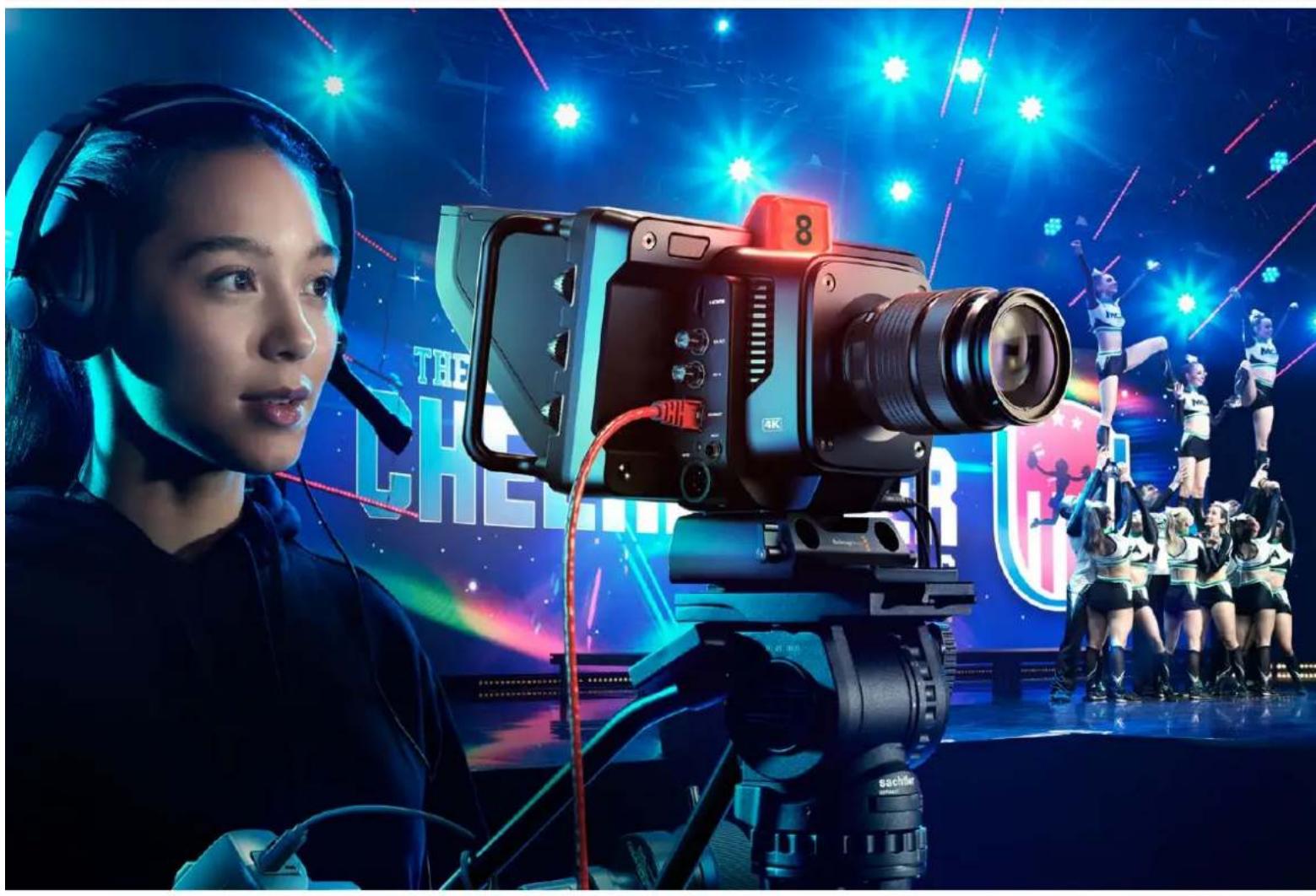

Gentile utente,
CEO Blackmagic Design
Indices
Blackmagic SDI Camera
Control Protocol 902
Example Protocol Packets 911
Blackmagic Embedded Tally
Control Protocol 912
Connetteri tally con Blackmagic
3G-SDI Shield for Arduino 914
Assistenza 916
Normative 917
Sicurezza 918
Garanzia 919
Bright, Contrast, Peaking
Frame rate off speed
Monitor -agina 1-LCD,HDMI,SDI
Monitor - SDI - Pgina 2
Film to Extended Video
Film to Rec 2020 Hybrid Log Gamma
Film to Rec 2020 PQ Gamma
If you are a software developer you can use the Blackmagic SDI to construct devices that integrate with our products. Here at Blackmagic Design, our approach is to open up our protocols and we eagerly look forward to seeing what you come up with!
Overview
This document describes an extensible protocol for sending a unidirectional stream of small control messages embedded in the non-active picture region of a digital video stream. The video stream containing the protocol stream may be broadcast to a number of devices. Device addressing is used to allow the sender to specify which device each message is directed to.
Assumptions
Alignment and padding constraints are explicitly described in the protocol document. Bit fields are packed from LSB first. Message groups, individual messages and command headers are defined as, and can be assumed to be, 32 bit aligned.
Blanking Encoding
A message group is encoded into a SMPTE 291M packet with DID/SDID x51/x53 in the active region of VANC line 16.
Message Grouping
Up to 32 messages may be concatenated and transmitted in one blanking packet up to a maximum of 255 bytes payload. Under most circumstances, this should allow all messages to be sent with a maximum of one frame latency.
If the transmitting device queues more bytes of message packets than can be sent in a single frame, it should use heuristics to determine which packets to prioritize and send immediately. Lower priority messages can be delayed to later frames, or dropped entirely as appropriate.
Abstract Message Packet Format
Every message packet consists of a three byte header followed by an optional variable length data block. The maximum packet size is 64 bytes.
| Destination device (uint8) | Device addresses are represented as an 8 bit unsigned integer. Individual devices are numbered 0 through 254 with the value 255 reserved to indicate a broadcast message to all devices. |
| Command length (uint8) | The command length is an 8 bit unsigned integer which specifies the length of the included command data. The length does NOT include the length of the header or any trailing padding bytes. |
| Command id (uint8) | The command id is an 8 bit unsigned integer which indicates the message type being sent. Receiving devices should ignore any commands that they do not understand. Commands 0 through 127 are reserved for commands that apply to multiple types of devices. Commands 128 through 255 are device specific. |
| Reserved (uint8) | This byte is reserved for alignment and expansion purposes. It should be set to zero. |
| Command data (uint8[]) | The command data may contain between 0 and 60 bytes of data. The format of the data section is defined by the command itself. |
| Padding (uint8[]) | Messages must be padded up to a 32 bit boundary with 0x0 bytes. Any padding bytes are NOT included in the command length. |
Receiving devices should use the destination device address and or the command identifier to determine which messages to process. The receiver should use the command length to skip irrelevant or unknown commands and should be careful to skip the implicit padding as well.
Defined Commands
Command 0: change configuration
| Category (uint8) | The category number specifies one of up to 256 configuration categories available on the device. |
| Parameter (uint8) | The parameter number specifies one of 256 potential configuration parameters available on the device. Parameters 0 through 127 are device specific parameters. Parameters 128 though 255 are reserved for parameters that apply to multiple types of devices. |
| Data type (uint8) | The data type specifies the type of the remaining data. The packet length is used to determine the number of elements in the message. Each message must contain an integral number of data elements. |
| Currently defined values are: | |
| 0: void / boolean | A void value is represented as a boolean array of length zero. The data field is a 8 bit value with 0 meaning false and all other values meaning true. |
| 1: signed byte Data elements are signed bytes | |
| 2: signed 16 bit integer Data elements are signed 16 bit values | |
| 3: signed 32 bit integer Data elements are signed 32 bit values | |
| 4: signed 64 bit integer Data elements are signed 64 bit values | |
5:UTF-8 string Data elements represent a UTF-8 string with no terminating character.
Data types 6 through 127 are reserved.
| 128: signed 5.11 fixed point | Data elements are signed 16 bit integers representing a real number with 5 bits for the integer component and 11 bits for the fractional component. The fixed point representation is equal to the real value multiplied by \( {2}^{ \land }{11} \) . The representable range is from -16.0 to 15.9995 (15 + 2047/2048). |
Data types 129 through 255 are available for device specific purposes.
Operation types 2 through 127 are reserved.
| Operation type (uint8) | The operation type specifies what action to perform on the specified parameter. Currently defined values are: |
| 0: assign value | The supplied values are assigned to the specified parameter. Each element will be clamped according to its valid range. A void parameter may only be 'assigned' an empty list of boolean type. This operation will trigger the action associated with that parameter. A boolean value may be assigned the value zero for false, and any other value for true. |
| 1: offset / toggle value | Each value specifies signed offsets of the same type to be added to the current parameter values. The resulting parameter value will be clamped according to their valid range. It is not valid to apply an offset to a void value. Applying any offset other than zero to a boolean value will invert that value. |
Operation types 128 through 255 are available for device specific purposes.
| Data (void) | The data field is 0 or more bytes as determined by the data type and number of elements. |
The category, parameter, data type and operation type partition a 24 bit operation space.
| Group | ID | Parameter | Type | Index | Minimum | Maximum | Interpretation |
| Lens | 0.0 | Focus | fixed16 | - | 0.0 | 1.0 | 0.0 = near, 1.0 = far |
| 0.1 | Instantaneous autofocus | void | - | - | - | trigger instantaneous autofocus | |
| 0.2 | Aperture (f-stop) | fixed16 | - | -1.0 | 16.0 | Aperture Value (where fnumber = sqrt(2^AV)) | |
| 0.3 | Aperture (normalised) | fixed16 | - | 0.0 | 1.0 | 0.0 = smallest, 1.0 = largest | |
| 0.4 | Aperture (ordinal) | int16 | - | 0 | n | Steps through available aperture values from minimum (0) to maximum (n) | |
| 0.5 | Instantaneous auto aperture | void | -- - | - | - | trigger instantaneous auto aperture | |
| 0.6 | Optical image stabilisation | boolean | - | - | - | true = enabled, false = disabled | |
| 0.7 | Set absolute zoom (mm) | int16 | - | 0 | max | Move to specified focal length in mm, from minimum (0) to maximum (max) | |
| 0.8 | Set absolute zoom (normalized) | fixed16 - 0.0 | 1.0 | - | - | Move to specified focal length: 0.0 = wide, 1.0 = tele | |
| 0.9 | Set continuous zoom (speed) | fixed16 - 1.0 | +1.0 | - | - | Start/stop zooming at specified rate: -1.0 = zoom wider fast, 0.0 = stop, +1 = zoom tele fast | |
| Video | 1.0 Video mode int8 | [0] = frame rate -- | fps as integer(eg 24, 25, 30, 50, 60) | ||||
| [1] = M-rate -- 0 = regular, 1 = M-rate | |||||||
| [2] = dimensions -- | 0 = NTSC, 1 = PAL, 2 = 720,3 = 1080, 4 = 2kDCI, 5 = 2k16:9,6 = UHD, 7 = 3k Anamorphic,8 = 4k DCI, 9 = 4k 16:9,10 = 4.6k 2.4:1, 11 = 4.6k | ||||||
| [3] = interlaced -- | 0 = progressive,1 = interlaced | ||||||
| [4] = Color space | -- 0 = YUV | ||||||
| 1.1 | Gain (up to Camera 4.9) | int8 | 1 | 128 | 1x, 2x, 4x, 8x, 16x, 32x, 64x, 128x gain | ||
| 1.2 | Manual White Balance | int16 | [0] = color temp | 2500 | 10000 | Color temperature in K | |
| int16 | [1] = tint | -50 | 50 | tint | |||
| 1.3 | Set auto WB | void | - | - | - | Calculate and set auto white balance | |
| 1.4 | Restore auto WB | void | - | - | - | Use latest auto white balance setting | |
| 1.5 | Exposure (us) | int32 | 1 | 42000 | time in us | ||
| 1.6 | Exposure (ordinal) | int16 | - | 0 | n | Steps through availableexposure values from minimum(0) to maximum (n) | |
| 1.7 | Dynamic Range Mode | int8 enum | - | 0 | 2 | 0 = film, 1 = video,2 = extended video | |
| 1.8 | Video sharpening level | int8 enum | - | 0 | 3 | 0 = off, 1 = low, 2 = medium,3 = high | |
| 1.9 Recording format | int16 | [0] = file frame rate | -- | fps as integer(eg 24, 25, 30, 50, 60, 120) | |||
| [1] = sensor frame rate | - | - | fps as integer, valid whensensor-off-speed set (eg 24,25, 30, 33, 48, 50, 60, 120),no change will be performed ifthis value is set to 0 | ||||
| [2] = frame width | -- in pixels | ||||||
| [3] = frame height | -- in pixels | ||||||
| [4] = flags | -- [0] = file-M-rate | ||||||
| - | - | [1] = sensor-M-rate, validwhen sensor-off-speed-set | |||||
| -- [2] = sensor-off-speed | |||||||
| -- [3] = interlaced | |||||||
| -- [4] = windowed mode | |||||||
| 1.10 | Set auto exposure mode | int8 | - | 0 | 4 | 0 = Manual Trigger, 1 = Iris,2 = Shutter, 3 = Iris + Shutter,4 = Shutter + Iris | |
| 1.11 | Shutter angle | int32 | - | 100 | 36000 | Shutter angle in degrees,multiplied by 100 | |
| 1.12 | Shutter speed | int32 | - | Currentsensorframe rate | 5000 | Shutter speed value as a fraction of 1, so 50 for 1/50th of a second | |
| 1.13 | Gain | int8 | - | -128 | 127 | Gain in decibel (dB) | |
| 1.14 | ISO | int32 | - | 0 | 2147483647 | ISO value | |
| 1.15 | Display LUT | int8 | [0] = selected LUT | -- | 0 = None, 1 = Custom,2 = film to video,3 = film to extended video | ||
| [1] = enabled or not | -- 0 = Not enabled, 1 = Enabled | ||||||
| 1.16 | ND Filter | fixed16 | [0] = stops | 0.0 | 16.0 | f-stop of ND filter to use | |
| Audio | 2.1 | Headphone level | fixed16 | - | 0.1 | 1.0 | 0.0 = minimum, 1.0 = maximum |
| 2.2 | Headphone program mix | fixed16 | - | 0.1 | 1.0 | 0.0 = minimum, 1.0 = maximum | |
| 2.3 | Speaker level | fixed16 | - | 0.1 | 1.0 | 0.0 = minimum, 1.0 = maximum | |
| 2.4 | Input type | int8 | - | 0 | 3 | 0 = internal mic,1 = line level input,2 = low mic level input,3 = high mic level input | |
| 2.5 Input levels fixed16 | [0] ch0 | 0.0 | 1.0 | 0.0 = minimum, 1.0 = maximum | |||
| [1] ch1 | 0.0 | 1.0 | 0.0 = minimum, 1.0 = maximum | ||||
| 2.6 | Phantom power | boolean | - | - | - | true = powered,false = not powered | |
| Output | 3.0 Overlay enables | uint16bit field | -- - | bit flags:[0] = display status,[1] = display frame guidesSome cameras don't allow separate control of frameguides and status overlays. | |||
| 3.1 | Frame guides style (Camera3.x) | int8 | -0 8 | 0 = HDTV, 1 = 4:3, 2 = 2:4:1,3 = 2.39:1, 4 = 2.35:1,5 = 1.85:1, 6 = thirds | |||
| 3.2 | Frame guides opacity(Camera 3.x) | fixed16 | - | 0.1 | 1.0 | 0.0 = transparent, 1.0 = opaque | |
| 3.3 | Overlays(replaces .1 and .2above fromCameras 4.0) | int8 | [0] = frame guidesstyle | - | - | 0 = off, 1 = 2.4:1, 2 = 2.39:1,3 = 2.35:1, 4 = 1.85:1, 5 = 16:9,6 = 14:9, 7 = 4:3, 8 = 2:1,9 = 4:5, 10 = 1:1 | |
| [1] = frame guide opacity | 0 | 100 | 0 = transparent, 100 = opaque | ||||
| [2] = safe area percentage | 0 | 100 | percentage of full frameused by safe area guide(0 means off) | ||||
| [3] = grid style | - | - | bit flags:[0] = display thirds,[1] = display cross hairs,[2] = display center dot,[3] = display horizon | ||||
| Display | 4.0 | Brightness | fixed16 | - | 0.0 | 1.0 | 0.0 = minimum, 1.0 = maximum |
| 4.1 Exposure and focus tools | int16bit field | 0x1 = zebra,0x2 = focus assist,0x4 = false color | - | - | 0 = disable, 1 = enable | ||
| 4.2 | Zebra level | fixed16 | - | 0.0 | 1.0 | 0.0 = minimum, 1.0 = maximum | |
| 4.3 | Peaking level | fixed16 | - | 0.0 | 1.0 | 0.0 = minimum, 1.0 = maximum | |
| 4.4 | Color bar enable | int8 | - | 0 | 30 | 0 = disable bars,1-30 = enable bars with timeout(seconds) | |
| 4.5 Focus Assist | int8 | [0] = focus assist method | - | - | 0 = Peak,1 = Colored lines | ||
| [1] = focus line color | - | - | 0 = Red,1 = Green,2 = Blue,3 = White,4 = Black | ||||
| 4.6 | Program return feed enable | int8 | - | 0 | 30 | 0 = disable, 1-30 = enable withtimeout (seconds) | |
| Tally | 5.0 | Tally brightness | fixed16 | - | 0.0 | 1.0 | Sets the tally front and tally rear brightness to the same level. 0.0 = minimum, 1.0 = maximum |
| 5.1 | Front tally brightness | fixed16 | - | 0.0 | 1.0 | Sets the tally front brightness. 0.0 = minimum, 1.0 = maximum | |
| 5.2 | Rear tally brightness | fixed16 | - | 0.0 | 1.0 | Sets the tally rear brightness. 0.0 = minimum, 1.0 = maximum Tally rear brightness cannot be turned off | |
| Reference | 6.0 | Source | int8 enum | - | 0 | 2 | 0 = internal, 1 = program, 2 = external |
| 6.1 | Offset | int32 | - | - | - | +/- offset in pixels | |
| Confi-guration | 7.0 Real Time Clock | int32 | [0] time | - | - | - | BCD - HHMMSSFF (UCT) |
| [1] date | - | - | - | BCD - YYYYYMMDD | |||
| 7.1 | System language | string | [0-1] | - | - | ISO-639-1 two character language code | |
| 7.2 | Timezone | int32 | - | - | - | Minutes offset from UTC | |
| 7.3 | Location | int64 | [0] latitude | - | - | BCD - sDDDdddddddddddd where s is the sign: 0 = north (+), 1 = south (-); DD degrees, ddddddddddd decimal degrees | |
| [1] longitude | - | - | BCD - sDDDdddddddddddd where s is the sign: 0 = west (-), 1 = east (+); DDD degrees, ddddddddddd decimal degrees | ||||
| Color Correction | 8.0 Lift Adjust fixed16 | [0] red -2.0 2.0 default | 0.0 | ||||
| [1] green -2.0 2.0 default | 0.0 | ||||||
| [2] blue -2.0 2.0 default | 0.0 | ||||||
| [3] luma -2.0 2.0 default | 0.0 | ||||||
| 8.1 | Gamma Adjust | fixed16 | [0] red -4.0 | 4.0 default 0.0 | |||
| [1] green -4.0 | 4.0 default 0.0 | ||||||
| [2] blue -4.0 | 4.0 default 0.0 | ||||||
| [3] luma -4.0 | 4.0 default 0.0 | ||||||
| 8.2 | Gain Adjust | fixed16 | [0] red 0.0 | 16.0 | default 1.0 | ||
| [1] green 0.0 | 16.0 | default 1.0 | |||||
| [2] blue 0.0 | 16.0 | default 1.0 | |||||
| [3] luma 0.0 | 16.0 | default 1.0 | |||||
| 8.3 Offset Adjust | fixed16 | [0] red -8.0 | 8.0 | default 0.0 | |||
| [1] green -8.0 | 8.0 | default 0.0 | |||||
| [2] blue -8.0 | 8.0 | default 0.0 | |||||
| [3] luma -8.0 | 8.0 | default 0.0 | |||||
| 8.4 | Contrast Adjust fixed16 | [0] pivot | 0.0 | 1.0 | default 0.5 | ||
| [1] adj | 0.0 | 2.0 | default 1.0 | ||||
| 8.5 | Luma mix | fixed16 | - | 0.0 | 1.0 | default 1.0 | |
| 8.6 Color Adjust | fixed16 | [0] hue | -1.0 | 1.0 | default 0.0 | ||
| [1] sat | 0.0 | 2.0 | default 1.0 | ||||
| 8.7 | Correction Reset Default | void | - | - | - | reset to defaults | |
| Media | 10.0 | Codec int8 enum | [0] = basic codec -- | 0 = Cinema/DNG, 1 = DNxHD, 2 = ProRes, 3 = Blackmagic RAW | |||
| [1] = code variant | - | - | Cinema/DNG: 0 = uncompressed, 1 = lossy 3:1, 2 = lossy 4:1 | ||||
| - | - | ProRes: 0 = HQ, 1 = 422, 2 = LT, 3 = Proxy, 4 = 444, 5 = 444XQ | |||||
| - | - | Blackmagic RAW: 0 = Q0, 1 = Q5, 2 = 3:1, 3 = 5:1, 4 = 8:1, 5 = 12:1 | |||||
| 10.1 | Transport mode int8 | [0] = mode | -- | 0 = Preview, 1 = Play, 2 = Record | |||
| [1] = speed | -- | -ve = multiple speeds backwards, 0 = pause, +ve = multiple speeds forwards | |||||
| [2] = flags | -- | 1<<0 = loop, 1<<1 = play all, 1<<5 = disk1 active, 1<<6 = disk2 active, 1<<7 = time-lapse recording | |||||
| [3] = slot 1 storage medium | - | - | 0 = CFast card, 1 = SD Card, 2 = SSD Recorder, 3 = USB | ||||
| [4] = slot 2 storage medium | - | - | 0 = CFast card, 1 = SD Card, 2 = SSD Recorder, 3 = USB | ||||
| 10.2 | Playback Control | int8 enum | [0] = clip | - | - | 0 = Previous, 1 = Next | |
| 10.3 | Still Capture | void | - | - | - | Capture | |
| PTZ Control | 11.0 | Pan/Tilt Velocity | fixed16 | [0] = pan velocity -1.0 | 1.0 | -1.0 = full speed left, 1.0 = full speed right | |
| [1] = tilt velocity | -1.0 | 1.0 | -1.0 = full speed down, 1.0 = full speed up | ||||
| 11.1 | Memory Preset | int8 enum | [0] = preset command | - | - | 0 = reset, 1 = store location, 2 = recall location | |
| int8 | [1] = preset slot | 0.5- | |||||
| Metadata | 12.0 | Reel | int16 | [0] = reel | 0 | 999 | - |
| 12.1 Scene Tags | signedbyte | [0] = scene tags | -- | -1 = None0 = WS1 = CU2 = MS3 = BCU4 = MCU5 = ECU | |||
| [1] = interior /exterior | - | - | 0 = Exterior1 = Interior | - | |||
| [2] = day / night | -- | 0 = Night1 = Day | - | ||||
| 12.2 | Scene | string | [0-4] = scene | - | - | - | |
| 12.3 | Take | signedbyte | [0] = take number | 1 | 99 | - | |
| [1] = take tags | -- | 1 = None0 = PU1 = VFX2 = SER | |||||
| 12.4 | Good Take | void | [0] = good take | - | - | - | |
| 12.5 | Camera ID | string | [0-28] = ID | - | - | - | |
| 12.6 | Camera Operator | string | [0-28] = operator | - | - | - | |
| 12.7 | Director | string | [0-27] = director | - | - | - | |
| 12.8 | Project Name | string | [0-28] = project | - | - | - | |
| 12.9 | Lens Type | string | [0-55] = type | - | - | - | |
| 12.10 | Lens Iris | string | [0-19] = iris | - | - | - | |
| 12.11 | Lens Focal Length | string | [0-29] = focal length | - | - | - | |
| 12.12 | Lens Distance | string | [0-49] = distance | - | - | - | |
| 12.13 | Lens Filter | string | [0-29] = filter | - | - | - | |
| 12.14 | Slate Mode | signedbyte | [0] = type | -- | 0 = Recording1 = Playback | ||
| 12.15 | Slate Target | string | [0-31] = name | - | - | - | |
Example Protocol Packets
| Operation | Packet Length Byte | ||||||||||||||||
| 0 | 1 | 2 | 3 | 4 | 5 | 6 | 7 | 8 | 9 | 10 | 11 | 12 | 13 | 14 | 15 | ||
| header command data | |||||||||||||||||
| destination | length | command | reserved | category | parameter | type | operation | ||||||||||
| trigger instantaneous auto focus on camera 4 | 844000100 | ||||||||||||||||
| turn on OIS on all cameras 12 | 25550006001000 | ||||||||||||||||
| set exposure to 10 ms on camera 4 (10 ms = 10000 us = 0x00002710) | 12 | 4 | 8 | 0 | 0 | 1 | 5 | 3 | 0 | 0x10 | 0x27 | 0x00 | 0x00 | ||||
| add 15% to zebra level (15 % = 0.15 f = 0x0133 fp) | 12 | 4 | 6 | 0 | 0 | 4 | 2 | 128 | 1 | 0x33 | 0x01 | 0 | 0 | ||||
| select 1080p 23.98 mode on all cameras | 16 | 255 | 9 | 0 | 0 | 1 | 0 | 1 | 0 | 24 | 1 | 3 | 0 | 0 | 0 | 0 | 0 |
| subtract 0.3 from gamma adjust for green & blue (-0.3 ^=0xff9a fp) | 16 | 4 | 12 | 0 | 0 | 8 | 1 | 128 | 1 | 0 | 0 | 0x9a | 0xffd | 0x9a | 0xffd | 0 | 0 |
| all operations combined | 76 | 440001002555000600 | |||||||||||||||
| 1 | 0 | 0 | 0 | 4 | 8 | 0 | 0 | 1 | 5 | 3 | 0 | 0x10 | 0x27 | 0x00 | 0x00 | ||
| 4 | 6 | 0 | 0 | 4 | 2 | 128 | 1 | 0x33 | 0x01 | 0 | 0 | 255 | 9 | 0 | 0 | ||
| 1 | 0 | 1 | 0 | 24 | 1 | 3 | 0 | 0 | 0 | 0 | 0 | 4 | 12 | 0 | 0 | ||
| 8 | 1 | 128 | 1 | 0 | 0 | 0x9a | 0xffd | 0x9a | 0xffd | 0 | 0 | ||||||
Blackmagic Embedded Tally Control Protocol
Version 1.0 (30/04/10)
This section is for third party developers or anybody who may wish to add support for the Blackmagic Embedded Tally Control Protocol to their products or system. It describes the protocol for sending tally information embedded in the non-active picture region of a digital video stream.
Data Flow
A master device such as a broadcast switcher embeds tally information into its program feed which is broadcast to a number of slave devices such as cameras or camera controllers. The output from the slave devices is typically fed back to the master device, but may also be sent to a video monitor.
The primary flow of tally information is from the master device to the slaves. Each slave device may use its device id to extract and display the relevant tally information.
Slave devices pass through the tally packet on their output and update the monitor tally status, so that monitor devices connected to that individual output may display tally status without knowledge of the device id they are monitoring.
Assumptions
Any data alignment / padding is explicit in the protocol. Bit fields are packed from LSB first.
Blanking Encoding
One tally control packet may be sent per video frame. Packets are encoded as a SMPTE 291M packet with DID/SDID x51/x52 in the active region of VANC line 15. A tally control packet may contain up to 256 bytes of tally information.
Packet Format
Each tally status consists of 4 bits of information:
uint4
bit 0: program tally status (0=off, 1=on)
bit 1: preview tally status (0=off, 1=on)
bit 2-3: reserved (0x0)
The first byte of the tally packet contains the monitor device tally status and a version number.
Subsequent bytes of the tally packet contain tally status for pairs of slave devices. The master device sends tally status for the number of devices configured/supported, up to a maximum of 510.
struct tally
uint8
bit 0: monitor device program tally status (0=off, 1=on)
bit 1: monitor device preview tally status (0=off, 1=on)
bit 2-3: reserved (0b00)
bit 4-7: protocol version (0b0000) uint8[0]
bit 0: slave device 1 program tally status (0=off, 1=on)
bit 1: slave device 1 device preview tally status (0=off, 1=on)
bit 2-3: reserved (0b00)
bit 4: slave device 2 program tally status (0=off, 1=on)
bit 5: slave device 2 preview tally status (0=off, 1=on)
bit 6-7: reserved (0b00)
uint8[1]
bit 0: slave device 3 program tally status (0=off, 1=on)
bit 1: slave device 3 device preview tally status (0=off, 1=on)
bit 2-3: reserved (0b00)
bit 4: slave device 4 program tally status (0=off, 1=on)
bit 5: slave device 4 preview tally status (0=off, 1=on)
bit 6-7: reserved (0b00)
中

| Byte 7 MSB 6 5 4 3 2 1 0 LSB | ||||||||
| 0 | Version (Ob0) | Version (Ob0) | Version (Ob0) | Version (Ob0) | Reserved (Ob0) | Reserved (Ob0) | Monitor Preview | Monitor Program |
| 1 | Reserved (Ob0) | Reserved (Ob0) | Slave 1 Preview | Slave 1 Program | Reserved (Ob0) | Reserved (Ob0) | Slave 0 Preview | Slave 0 Program |
| 2 | Reserved (Ob0) | Reserved (Ob0) | Slave 3 Preview | Slave 3 Program | Reserved (Ob0) | Reserved (Ob0) | Slave 2 Preview | Slave 2 Program |
| 3 | ... | |||||||
Connette il tally con Blackmagic 3G-SDI Shield for Arduino
Supporto online Blackmagic Design
o Heads-Up Display 936
DaVinci Resolve 1001
Developer Information 1004
Blackmagic SDI Camera
Control Protocol 1004
Example Protocol Packets 1013
Blackmagic Embedded Tally
Control Protocol 1014
m = 311
00:
00:00
0:00
[EX]
IN dB
wn 56
DOK
TINT 10