C5000 - Home cinema amp YAMAHA - Free user manual and instructions
Find the device manual for free C5000 YAMAHA in PDF.
| Product type | Stereo preamplifier |
| Brand | YAMAHA |
| Model | C5000 |
| Dimensions (W × H × D) | 435 × 142 × 451 mm |
| Weight | 19.1 kg |
| Power consumption | 60 W |
| Standby consumption | 0.2 W (standby), 0.1 W (power off) |
| Power supply | 230 V AC, 50 Hz (Europe model) |
| Symmetrical design | Mirror-image left-right symmetrical design |
| Class amplification | Class A operation at all stages |
| Signal transmission | Floating balance from input to output |
| Phono preamp | Balanced and floating ground with balanced XLR and unbalanced RCA inputs |
| Controls | Ultra-precise with exclusive bearing structure and highly rigid lever selectors |
| Transformer | Dual specially designed audio transformer, independent power supply |
| Mechanical construction | Stable mechanical mass reducing external vibrations |
| Tone circuit | Exclusive parallel volume system for BASS and TREBLE |
| Feet | Newly designed brass spike feet, height adjustable |
| Gain function | Gain control for extremely fine volume adjustment (GAIN selector: -12, -6, 0 dB) |
| Inputs | Phono (XLR/RCA), BAL 1/2 (XLR), TUNER, CD, LINE 1/2 (RCA), EXT. IN (XLR/RCA) |
| Outputs | BAL (XLR), LINE 1/2 (RCA), LINE 2 OUT (recording), headphone jack (PHONES) |
| Connectivity | TRIGGER IN/OUT, infrared remote control, remote connection (REMOTE IN/OUT) |
| Maintenance and cleaning | Use a soft dry cloth. For mirror-finished side panels, use a piano cloth. Do not use chemical products. |
| Safety | Do not use the power cord with other devices. Disconnect during storms or prolonged non-use. |
| Supplied accessories | Remote control, AAA batteries (×2), power cord, instruction manual, safety brochure |
Frequently Asked Questions - C5000 YAMAHA
User questions about C5000 YAMAHA
0 question about this device. Answer the ones you know or ask your own.
Ask a new question about this device
Download the instructions for your Home cinema amp in PDF format for free! Find your manual C5000 - YAMAHA and take your electronic device back in hand. On this page are published all the documents necessary for the use of your device. C5000 by YAMAHA.
USER MANUAL C5000 YAMAHA
Thank you and congratulations on your purchase of this Yamaha product.
You can enjoy the high-quality stereo sound of this preamplifier at home.
This Owner's Manual describes the unit's features, connection procedures, and operations.
To use the product properly and safely, we suggest that you read this manual and Safety Brochure (separate booklet) thoroughly.
Keep the manual in a safe, accessible place for future reference.
You can download a PDF version of this manual from the following Yamaha website.
https://download.yamaha.com/
Features
Left-right symmetrical design creates a bookmarked structure
Class A operation of full-stage, full-floating balanced signal transmission from input to output
Full-floating and balanced phono EQ amplifier with balanced inputs
High-accuracy controls that employ a proprietary bearing structure and high-rigidity lever switches
Twin transformer designed specifically for audio, which is completely separate from the control power supply
Stable mechanical grounding construction dramatically lessens the impact of external vibration.
Tone control circuit that features a proprietary parallel volume system
Newly-designed brass spiked feet
Gain control function that enables ultra fine volume adjustment
About this manual
The illustrations as shown in this manual are for instructional purposes only.
The company names and product names in this manual are the trademarks or registered trademarks of their respective companies.
“WARNING” describes precautions to be followed to avoid the possibility of serious injury or even death.
CAUTION describes precautions to be followed to avoid the possibility of injury.
"NOTICE" describes precautions to be followed to avoid the possibility of malfunction/damage to the product, or damage to data.
"Note" describes supplemental information about the product.
Before starting to use the product, please be sure to read the separate "Safety Brochure".
Table of contents
Features 2
About this manual 2
Supplied accessories 4
Maintenance 4
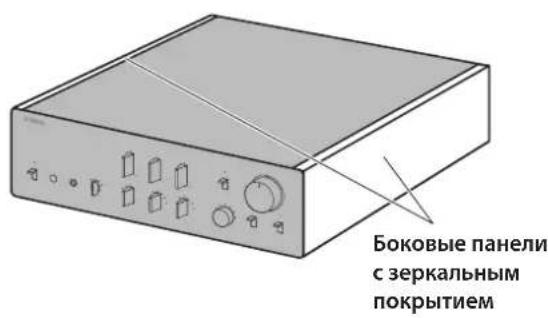
Mirror-finish side panels. 4
Surfaces other than the mirror-finish side panels 4
Part Names and Functions
Front panel 6
Rear panel. 10
Balanced and unbalanced connections . . 14
Remote control 16
Installing batteries in the remote control. .18
Operating the remote control 18
Connections
Connecting an external component 20
Connecting a turntable 22
Connecting a recording component 22
Connecting another preamplifier 23
Connecting a power amplifier and an active subwoofer 23
Trigger connections 24
Controlling the power on-and-off operation of a connected component, such as a power amplifier, in sync with this unit. 24
Controlling the unit's power on-and-off operation in sync with a connected component, such as an AV receiver. 24
Remote connections 25
Operating the unit from another room 25
Remote connection between Yamaha components 25
Connecting the power cord. 26
Operations
Turning the power on 28
Selecting the input and output 28
Selecting the input from the EXT.IN jacks...29
Adjusting the turntable input setting 29
PHONO selector 29
Subsonic filter 30
Adjusting the volume level 30
Lowering the volume level momentarily . . 31
Adjusting the tone 31
Connecting headphones 32
Reference Materials
General specifications 34
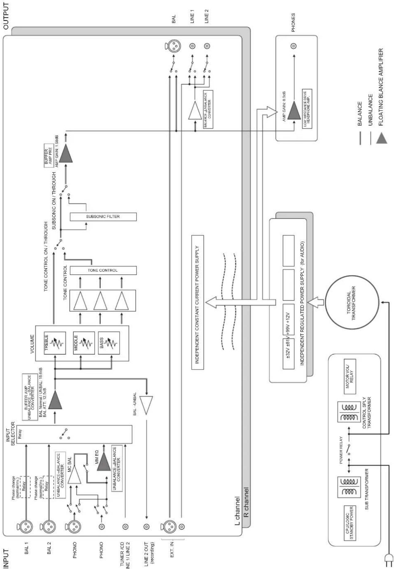
Block diagram 36
Audio characteristics 37
Frequency response (tone control) 37
Total harmonic distortion (PHONO). 37
Frequency response (subsonic filter) 38
Volume curve. 38
Troubleshooting. 39
Index 41
Supplied accessories
Please make sure that the following accessories are included in the package.
Remote control
Batteries (AAA, R03, UM-4) (x2)
Power cord
Owner's Manual (this book)
Safety Brochure (separate booklet)

WARNING
Do not use the supplied power cord for other devices.
Maintenance
To use this product for an extended period of time, we recommend that you maintain it regularly.

WARNING
- Check the power cord regularly to see if it is dusty. If so, wipe off the dust completely. Otherwise, fire or electric shock might be caused.
- Do not use aerosol or flammable gas spray for cleaning or lubrication. Otherwise, flammable gas will build up inside the unit, causing possible explosion or fire.
NOTICE
- Use a dry soft cloth to clean the unit. Using cleaning agents, such as benzene or thinner, detergent, or chemically-treated cloth might cause color changes or deterioration of the surface. If the surface gets very dirty, damp a cloth with detergent (diluted with water), wring the cloth tightly, and wipe off the dirt.
- If you wipe the surface area in the vicinity of the Yamaha logo with force, the logo might peel off or fiber from the cloth might stick to the surface.
Mirror-finish side panels
We recommend that you use a cleaning cloth such as those made for pianos. If the surface is very dirty, use a soft cloth that is damp with water and wrung tightly.
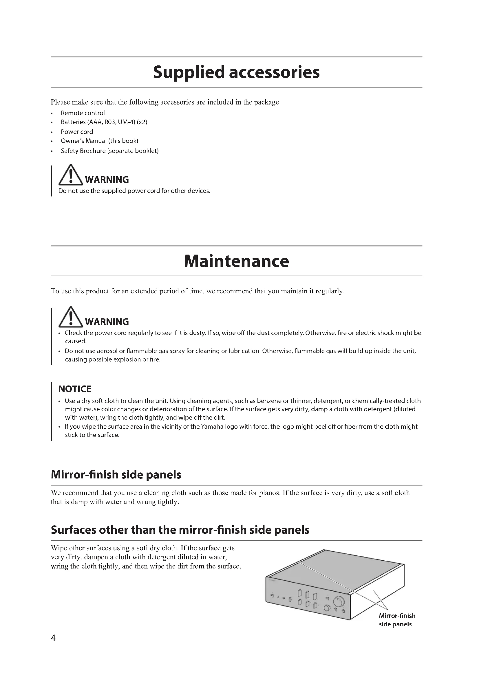
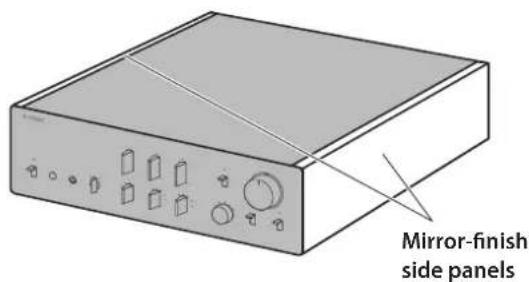
Surfaces other than the mirror-finish side panels
Wipe other surfaces using a soft dry cloth. If the surface gets very dirty, dampen a cloth with detergent diluted in water, wring the cloth tightly, and then wipe the dirt from the surface.
Part Names and Functions
This section lists the names and describes the function of various parts on the front and rear panels, and the remote control.
Front panel

NATURAL SOUND PRE-AMPLIFIER C-6000
STANDBY/ON
2

4
5
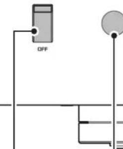
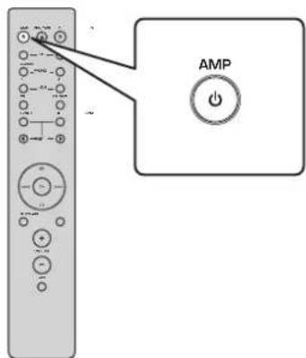
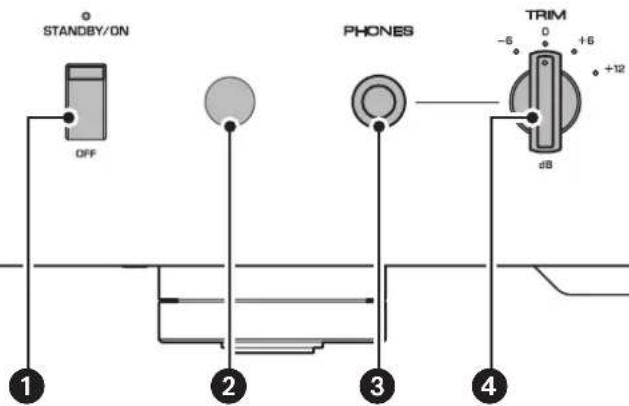
1 STANDBY/ON/OFF (Power) switch/indicator
Turns the power to the unit on (standby) or off.
STANDBY/ON: Switches between standby and on using the AMP key on the remote control.
OFF:Turns the power to the unit off.
| Power status Indicator | |
| On mode Lit brightly | |
| Standby mode Lit dimly | |
| Off mode Off |
The unit will enter standby mode not only when you press the AMP key on the remote control, but also in one of the following events:
- If the unit is powered on but not operated for eight hours while the auto power standby function is turned on, or
- If you turn off the power to the device that is connected to this unit's TRIGGER IN jack.
For more information, refer to "AUTO POWER STANDBY switch" in the "Rear panel" section (page 13) and to "Trigger connections" (page 24).
Note
After you turn on the unit, it will take a few seconds before the unit can reproduce sound.
NOTICE
If you plan not to use the unit for an extended period of time, be sure to unplug the power cord from the AC outlet. Even when the STANDBY/ON/OFF (Power) switch is turned off (the power indicator is dark), a minimal amount of electric current is still flowing to the unit.
Remote control sensor
Receives signals from the remote control. For more information, refer to "Operating the remote control" (page 18).
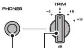
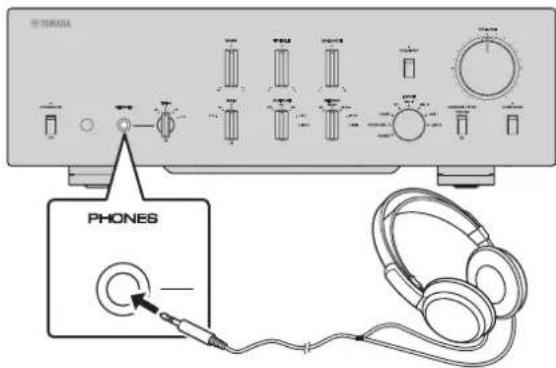
3 PHONES jack
Connect your headphones here to listen to music privately. For more information, refer to "Connecting headphones" (page 32).

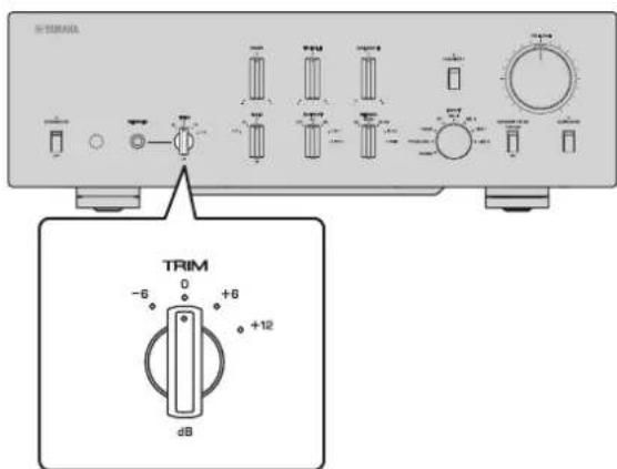
4 TRIM selector
Switches the headphone amp gain. The unit will adjust the volume level when headphones are plugged in to avoid sudden changes in volume by modifying the level balance between the audio output from the PHONES jack and from the speakers.
Choices: -6 dB, 0 dB, +6 dB, +12 dB
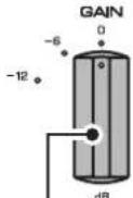
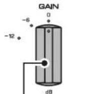
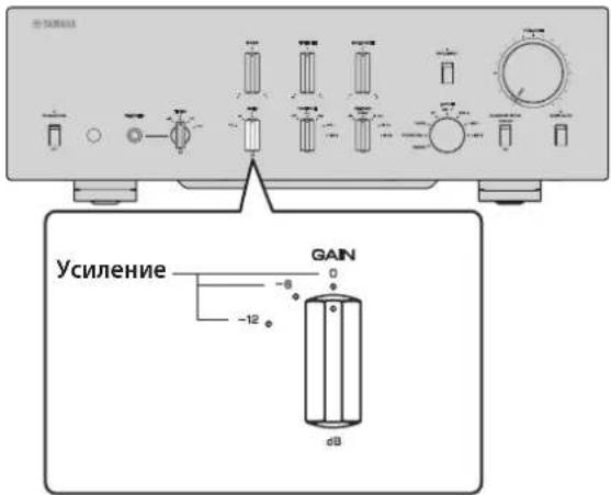
GAIN selector
Switches the preamp gain. The unit will smoothly adapt to the power amp gain and speaker sensitivity, enabling you to make fine volume adjustments. For more information, refer to "Adjusting the volume level" (page 30).
Choices: -12 dB, -6 dB, 0 dB
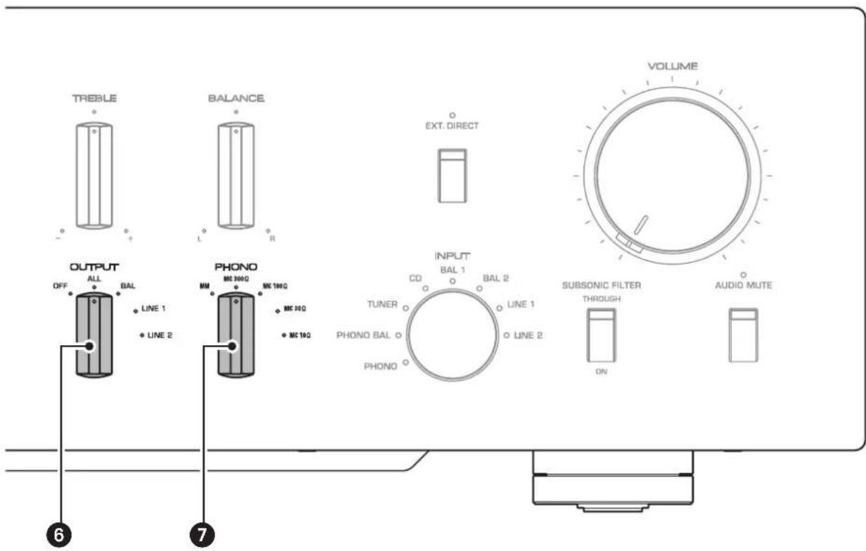
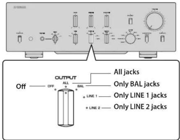
OUTPUT selector
Specifies which OUTPUT jacks will output signals, as follows:
Use this selector if multiple power amplifiers are connected.
| OUTPUT selector | |||||
| OFF ALL BAL LINE1 LINE2 | |||||
| BAL jacks | — | Output | Output | — | — |
| LINE 1 jacks | — | Output | — | Output | — |
| LINE 2 jacks | — | Output | — | — | Output |
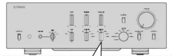
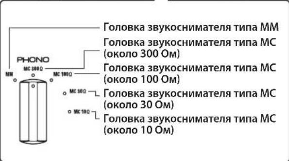
7 PHONO selector
Indicates the type of cartridge installed on the turntable that is connected to the PHONO jacks on the rear panel (MM, MC 300Ω, MC 100Ω, MC 30Ω, MC 10Ω). For more information, refer to "Adjusting the turntable input setting" (page 29).
NOTICE
Before you replace the cartridge, be sure to turn off the power to this unit.
Front panel
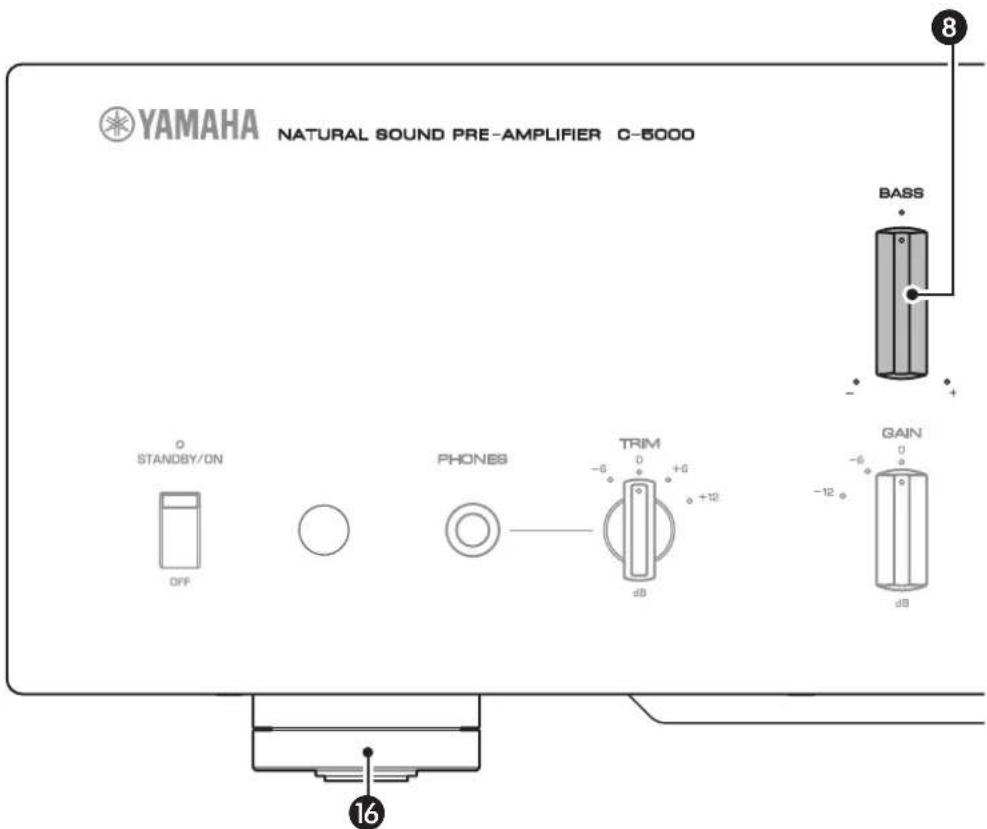
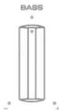
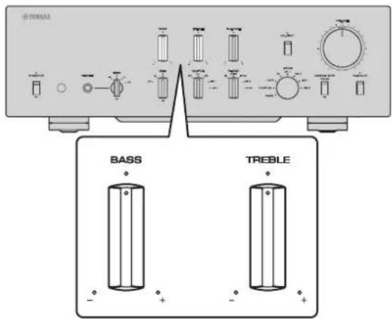
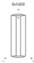
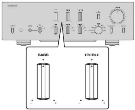
BASS control
Adjusts the low-frequency response in the range from -10dB to +10dB (in 0.5 dB steps). The center position produces a flat response.
9 TREBLE control
Adjusts the high-frequency response in the range from -10dB to +10dB (in 0.5 dB steps). The center position produces a flat response.
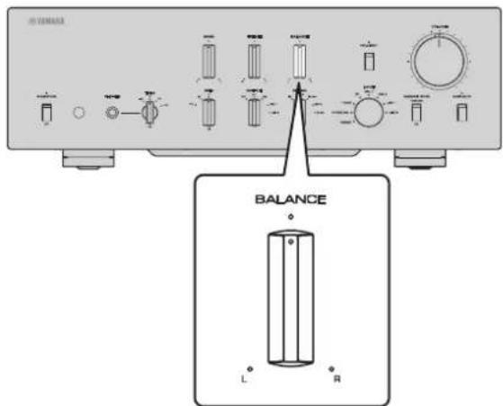
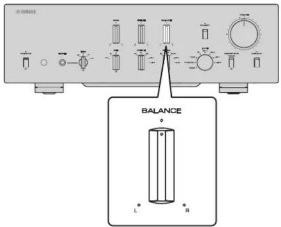
10 BALANCE control
Adjusts the audio output balance between the left and right speakers in the range from L (the right channel is muted) to R (the left channel is muted) to compensate for sound imbalances caused by speaker locations or listening room conditions.
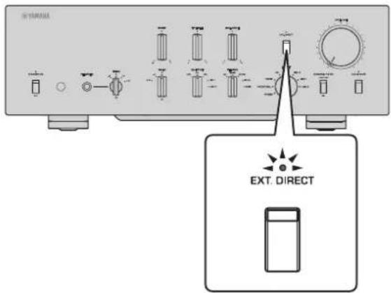
EXT. DIRECT switch/indicator
If you press the EXT. DIRECT switch once, the EXT. DIRECT indicator will light up, and the audio source input at the EXT. IN jacks will be output at the connected output jacks. For more information, refer to "Connecting another preamplifier" (page 23) and "Selecting the input and output" (page 28).
If you press the EXT. DIRECT switch again or rotate the INPUT selector, the signal specified by the INPUT selector will become the input source, and the EXT. DIRECT indicator will turn off.
Note
If EXT. DIRECT is selected, no signal will be output at the LINE 2 OUT (recording) jacks nor at the PHONES jack.
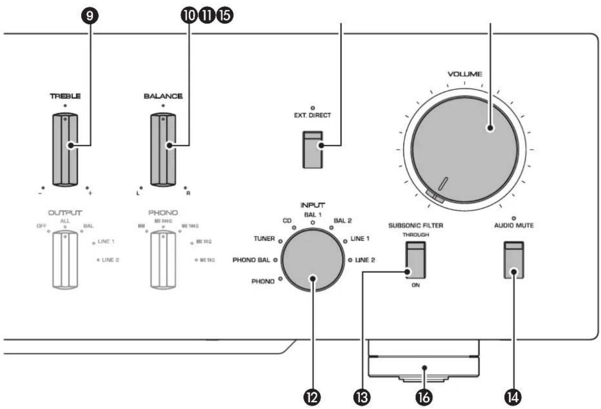
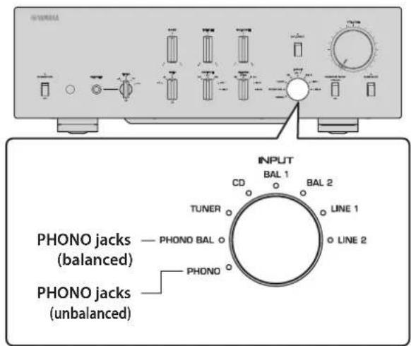
INPUT selector/indicator
Enables you to select the input source to play back. Options are: PHONO, PHONO BAL, TUNER, CD, BAL 1, BAL 2, LINE 1, and LINE 2. The indicator for the selected input source lights up.
Note
If LINE 2 is selected here, audio signals will not be output at the LINE 2 OUT (recording) jacks.
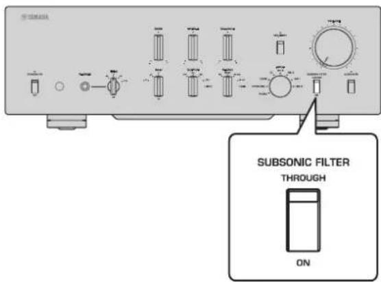
SUBSONIC FILTER switch
Toggles between ON (enabled) and THROUGH (disabled) for the subsonic filter. For more information, refer to "Adjusting the turntable input setting" (page 29).
Note
If the INPUT selector is set to any option other than PHONO or PHONO BAL, the filter will be disabled.
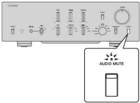
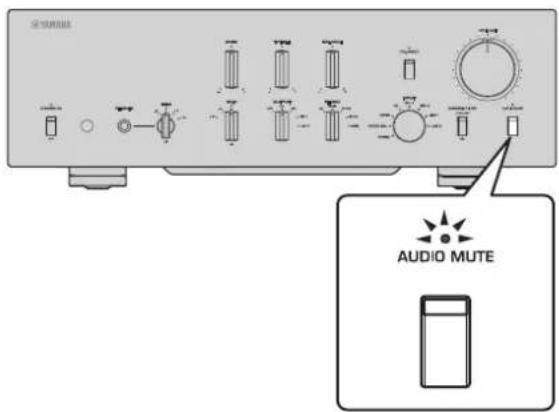
AUDIO MUTE switch/indicator
Press this switch to reduce the current volume level by approximately 20dB . The indicator will light up. Press again to restore the audio output to the previous volume level. The indicator will turn off.
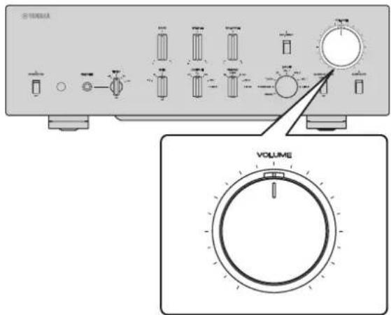
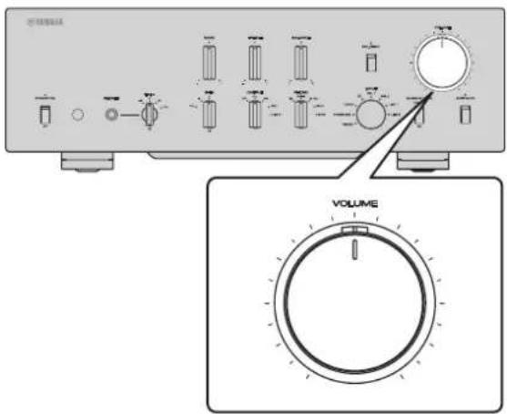
15 VOLUME control
Adjusts the volume level. This setting will not affect the output level at the LINE 2 OUT (recording) jacks.
Note
The VOLUME control will not affect the volume level if EXT. DIRECT is selected as the input source. To adjust the volume level, use the volume control on the external preamplifier or another component connected to the EXT. IN jacks.
16 Feet
If the unit is unstable, adjust the height of the feet as needed by rotating them.
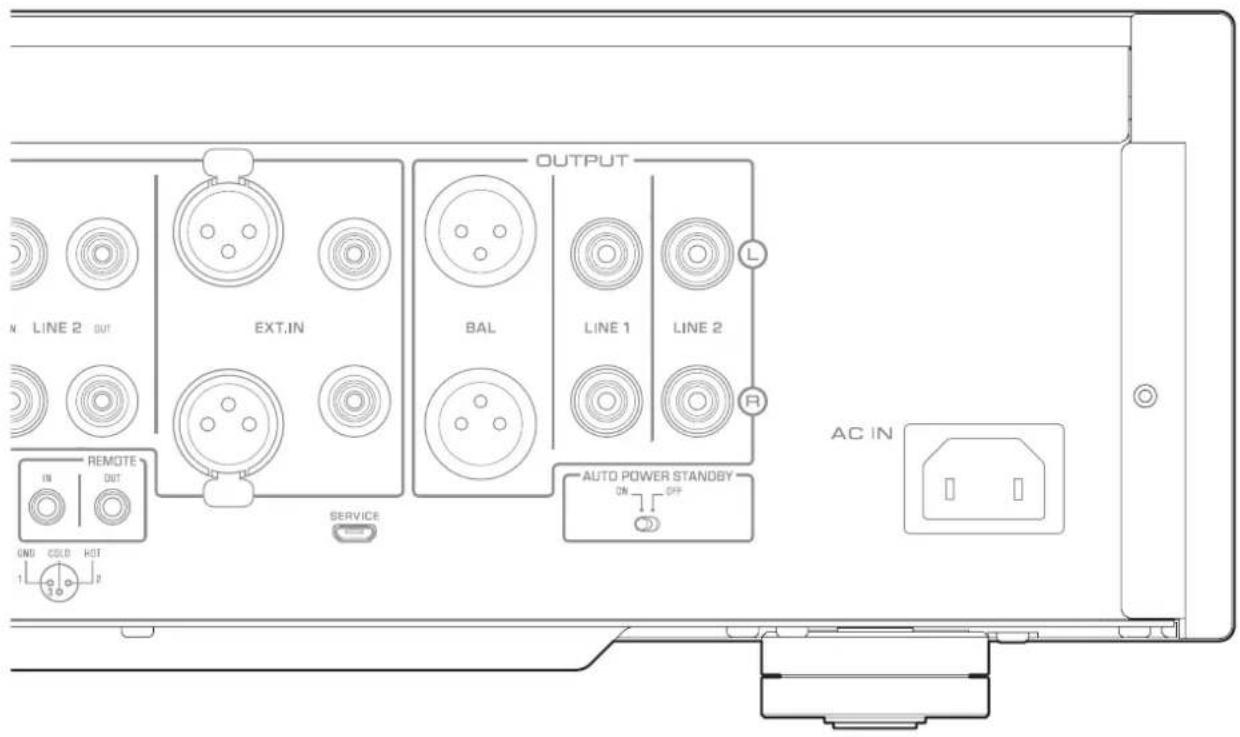
Rear panel
Note
For information regarding the connection procedure, refer to "Connections" (page 19).
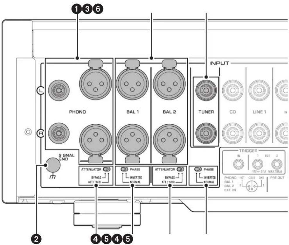
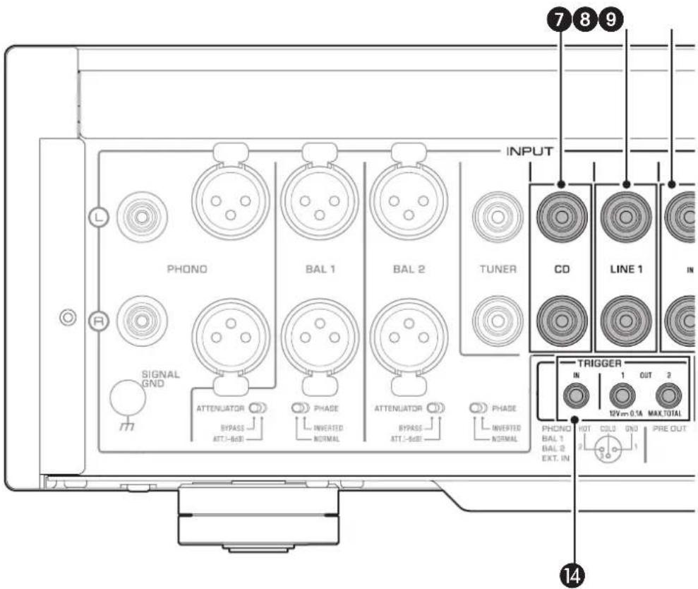
1 PHONO jacks
RCA and XLR-type jacks. If the INPUT selector is set to PHONO, the signals at the RCA-type PHONO jacks will be the input source. If the INPUT selector is set to PHONO BAL, the signals at the XLR-type PHONO jacks will be the input source.
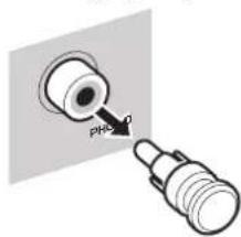
Your preamplifier comes with a shorting plug installed on each RCA-type PHONO input jack. If you are planning to connect an external component to these jacks, remove the shorting plugs. For more information, refer to "Connecting a turntable" (page 22).

CAUTION
Handle the shorting plugs carefully. Do not allow children to play with the shorting plug; otherwise they might swallow it.
NOTICE
- Shorting plugs are intended for unused INPUTS ONLY; using them on OUTPUTS can cause serious damage to your components.
If you are planning not to use the RCA-type PHONO input jacks, insert the shorting plugs into the jacks to prevent random static or noise from degrading the audio signal.
2 SIGNAL GND (ground) terminal
If you connect your turntable to the RCA-type PHONO input jacks, also connect the turntable to this terminal. Doing so may reduce noise.

BAL 1/BAL 2 jacks
These are two sets of XLR-type balanced input jacks. If the INPUT selector is set to BAL 1 or BAL 2, signals at the corresponding XLR jacks will be the input source.
Note
Set the ATTENUATOR selector and PHASE selector appropriately for the playback components that are connected to the unit.
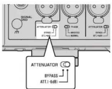
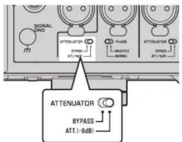
4 ATTENUATOR selector
Enables you to set the allowable input level for the XLR-type balanced input jacks (BAL 1 and BAL 2 jacks). For more information, refer to "Adjusting the volume level" (page 30).
BYPASS The allowable input level will not change. Usually select this option.
ATT. (-6 dB). The input gain will be lowered by 6 dB to raise the allowable input level. Select this option if the audio output from the connected component sounds distorted.
5 PHASE selector
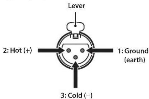
Specifies the HOT pin position for the XLR-type balanced input jacks (BAL 1 and BAL 2 jacks).
NORMAL: Pin #2 is specified as HOT.
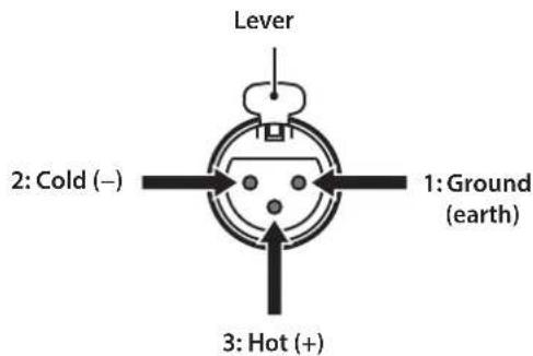
INV: Pin #3 is specified as HOT.
For more information, refer to "Balanced and unbalanced connections" (page 14).
TUNERjacks
These are RCA input jacks. If the INPUT selector is set to TUNER, signals at these jacks will be the input source. Connect your tuner here.
Rear panel

CDjacks
These are RCA input jacks. If the INPUT selector is set to CD, signals at these jacks will be the input source. Connect your CD player here.
8 LINE 1 jacks
These are RCA input jacks. If the INPUT selector is set to LINE 1, signals at these jacks will be the input source.
LINE 2 IN jacks
These are RCA input jacks. If the INPUT selector is set to LINE 2, these jacks will be the input source.
LINE 2 OUT (recording) jacks
These are RCA input jacks for recording. These jacks normally output the input source signals selected via the front panel or remote control. For information on the connection procedure, refer to "Connecting a recording component" (page 22).
Note
- Connect the LINE 2 IN jacks and LINE 2 OUT (recording) jacks to the same component.
- The LINE 2 OUT (recording) jacks will not output any signals if the INPUT selector is set to LINE 2 or the EXT. DIRECT switch is pressed.
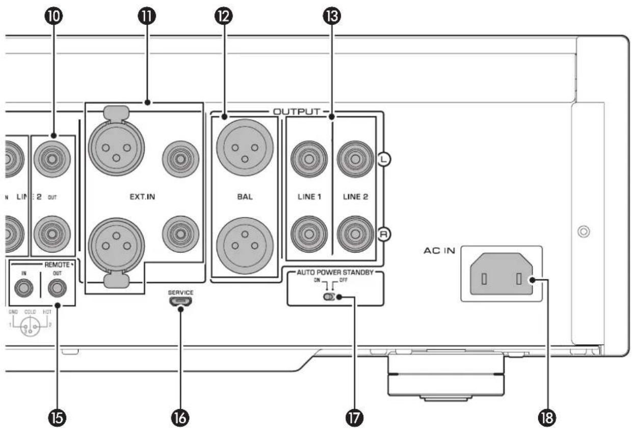
EXT.IN jacks
These jacks feature XLR-type input jacks and RCA input jacks. If the EXT. DIRECT switch is pressed, signals at these jacks will be the input source. Connect your preamplifier here. For more information, refer to "Connecting another preamplifier" (page 23).

CAUTION
You cannot adjust the volume level of the signals input at the EXT. IN jacks. Therefore, be sure to connect to the EXT. IN jacks a component that features a volume control.

Note
The volume level is fixed. Operating the VOLUME control or GAIN selector on this unit will not change the volume level of the signal from the EXT. IN jacks. Adjust the volume level using the volume control on the component connected to the EXT. IN jacks.

BAL jacks
These are XLR-type output jacks. Connect these jacks to the balanced input jacks on the power amplifier.

LINE 1/LINE 2 jacks
These are RCA output jacks. Connect these jacks to the RCA input jacks on the power amplifier.

TRIGGER IN/TRIGGER OUT jacks
These are monaural mini jacks. Connect external components that support the trigger function here. For more information, refer to "Trigger connections" (page 24).

REMOTE IN/REMOTE OUT jacks
These are monaural mini jacks. Connect external components that support the remote function here. For more information, refer to "Remote connections" (page 25).

SERVICE jack
This jack is used to service the product. It is rarely used.

AUTO POWER STANDBY switch
Specifies whether the unit automatically enters standby mode.
ON: The unit enters standby mode automatically if it is powered on but not operated for eight hours.
OFF: The unit does not enter standby mode automatically.

AC IN jack
Connect the supplied power cord here. For more information, refer to "Connecting the power cord" (page 26).
Balanced and unbalanced connections
This unit features XLR-type balanced jacks and RCA-type unbalanced input jacks.
Note
Do not use balanced and unbalanced connections between two components simultaneously. Doing so would create a ground loop that could generate static and noise.
Balanced connection
A balanced connection is designed to cancel and prevent unwanted noise. Since longer cables tend to pick up more noise, a balanced connection is useful if you need to use long cables. Generally, if your components feature balanced outputs, you should use balanced connections.
Jacks for balanced connections
XLR-type jacks on this unit are used for balanced connections. The input and output jacks utilize different designs. Input jacks are female, and output jacks are male. For balanced connections, balanced cables with XLR connectors are used. Connect a male connector on the cable to a female jack on the unit, and connect a female connector to a male jack on the unit.
XLR connector (female) XLR jack (male)
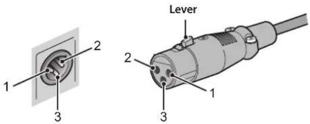
When connecting a cable to an output jack, be sure to align the holes on the connector with the pins on the jack, and then insert the connector into the jack until you hear a click. To remove the cable, while pressing and holding down the lever on the female XLR connector, pull it out from the jack.
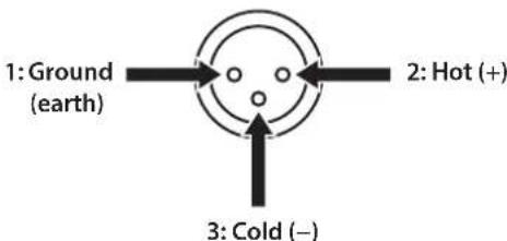
Balanced connection polarity
When making a balanced connection, you must set the polarity correctly. Generally, pin #2 is Hot, but sometimes pin #3 can be Hot. Refer to the owner's manual for the connected component to learn which pin at the output jack is Hot.
To set the polarity for the BAL 1 and BAL 2 input jack pins, use the PHASE selector on the rear panel.
XLR connector (male)XLR jack (female) Note

- The PHONO and EXT. IN jacks do not feature a PHASE switch. The pin polarity of these jacks is standard and fixed.
Pin #2 is Hot on Yamaha players.
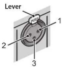
When connecting a cable to an input jack, be sure to align the pins on the connector with the holes in the jack, and then insert the connector into the jack until you hear a click. To remove the cable, while pressing and holding down the lever on the input jack on the unit, pull out the male XLR connector from the jack.
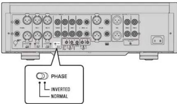
If the PHASE selector is set to NORMAL, pin #2 becomes Hot.
XLR-type input jack
If the PHASE selector is set to INVERTED, pin #3 becomes Hot.
XLR-type input jack
XLR-type output jack
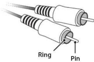
Unbalanced connection
If you are connecting an audio component that features only standard RCA jacks, use the RCA jacks on this unit for unbalanced connections. For unbalanced connections, unbalanced cables with RCA connectors should be used. These jacks and connectors do not feature a male or female design nor polarity differences.
Remote control
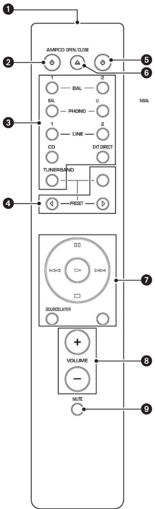
Infrared signal transmitter
Outputs infrared control signals toward the unit.
2 AMP key
Turns on the power to the unit or switches it to standby mode. For more information regarding standby mode, refer to "Front panel" (page 6).
Input select keys
Enable you to select the input source to be played back.
BAL: Selects the component connected to the XLR-type BAL 1 or BAL 2 jacks as the input source.
PHONO: Selects the turntable connected to the PHONO jacks (XLR-type or RCA) as the input source. Press the BAL key to select the source at the XLR-type jacks, or the UNBAL key to select the source at the RCA jacks.
LINE: Selects the component connected to the RCA-type LINE 1 or LINE 2 jacks as the input source.
EXT. DIRECT: Selects the component connected to the EXT. IN jacks as the input source. If EXT. DIRECT is selected as the input source, audio signals will not be output at the LINE 2 OUT or PHONES jacks.
CD: Selects the component (usually, a CD player) connected to the RCA-type CD jacks as the input source.
TUNER: Selects the component (usually, a tuner) connected to the RCA-type TUNER jacks as the input source.
Note
Audio signals of the selected input source will be output at the LINE 2 OUT (recording) jacks. If LINE 2 is selected as the input source, audio signals will not be output at the LINE 2 OUT (recording) jacks.
4 Tuner control keys
Enable you to control the functions of the connected Yamaha tuner. Use the BAND key to switch the reception band, and the PRESET keys to select a preset station. For more information, refer to the owner's manual for your tuner.
Note
Some Yamaha tuner models might not support these key functions.
CD key
Turns on the power to a connected Yamaha CD player, or switches it to standby mode.
OPEN/CLOSE key
Opens or closes the disc tray of a connected Yamaha CD player. For more information, refer to the owner's manual for your CD player.
Note
Some Yamaha CD player models might not support the
CD key and/or OPEN/CLOSE key functions.
CD player control keys
Enable you to control the functions of a connected Yamaha CD player. For more information, refer to the owner's manual for your CD player.
(Play)
Starts playback.
(Pause)
Pauses playback. Press to time playback.
(Stop)
Stops playback.
1-√D(Shift)
Skipping to the next track, or returns to the beginning of the current track.
SOURCE key
Selects the source to be played on the Yamaha CD player. The playback source changes each time this key is pressed.
LAYER key
Toggles the playback layer of a hybrid super audio CD between "Super audio CD" and "CD."
Note
Some Yamaha CD player models might not support these key functions.
8 VOLUME + / - keys
Adjust the volume level.
Note
The VOLUME + / - keys on the remote control will not affect the volume level if EXT. DIRECT is selected as the input source. To adjust the volume level, use the volume control on the external amplifier connected to the EXT. IN jacks.
9 MUTE key
Reduces the current volume level by approximately 20 dB. Press the key again to restore the audio output to the previous volume level. Pressing the VOLUME + or -key on the remote control will also cancel muting.
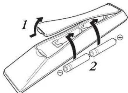
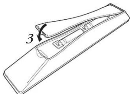
Installing batteries in the remote control
1 Remove the battery compartment cover.
2 Insert two batteries (AAA, R03, UM-4) according to the polarity markings (+ and -) on the inside of the battery compartment.
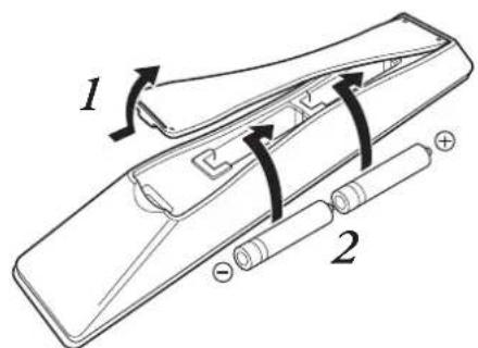
3 Reinstall the battery compartment cover.


WARNING
- Do not toss the batteries into an open fire, or expose them to high temperatures, such as direct sunlight or open flame. Otherwise, the battery might explode, causing fire or injury.
- Do not try to recharge non-rechargeable batteries. Otherwise, batteries might explode or leak, causing blindness, chemical burns or injury.
If a battery is leaking, do not touch the liquid. Otherwise, blindness or chemical burns might be caused. If your eyes, mouth, or skin comes in contact with the liquid, immediately wash the site thoroughly with water and seek medical attention.

CAUTION
- Do not use a new and old batteries at the same time. Otherwise, fire, burns, or irritation due to leaking battery liquid might be caused.
- Do not use two different types of batteries at the same time. For example, if you use an alkaline battery and a manganese battery together, or two batteries from two different manufacturers or with different product numbers at the same time, fire, burns, or skin irritation due to leaking battery liquid might be caused.
- Keep the batteries out of the reach of children. Otherwise, a child might swallow the battery by accident. Also, leaking battery liquid might cause skin irritation.
- Insert the two batteries according to the polarity markings (+ and -). Otherwise, fire, burns, or skin irritation due to leaking battery liquid might be caused.
If you plan not to use the remote control for an extended period of time, or if the batteries are exhausted completely, remove them from the remote control. Otherwise, all batteries will eventually become exhausted and might leak, causing skin irritation or damage to the remote control.
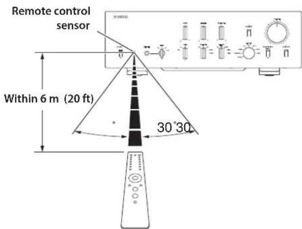
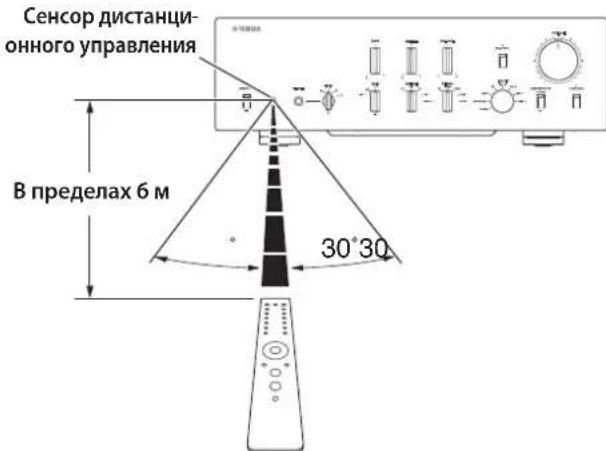
Operating the remote control
To operate the remote control, aim it directly at the remote control sensor on the front panel of the unit.
Connections
This section explains how to connect the unit to an audio source, such as a tuner or CD player, and a power amplifier.

CAUTION
Turn off the power to all components before making any connections.
NOTICE
- Do not use balanced and unbalanced connections between two components simultaneously. Doing so would create a ground loop that could generate static and noise.
- If you are planning to connect external components, read and follow the instruction manuals for those components. Otherwise, this unit or external components might malfunction.
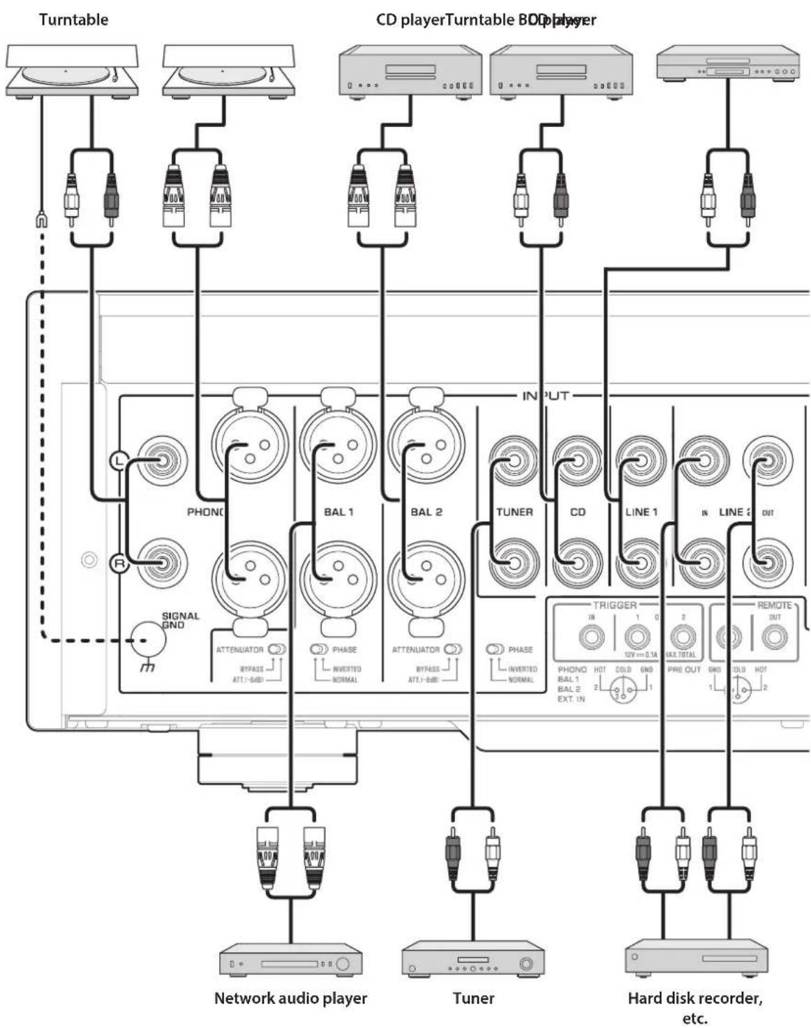
Connecting an external component
NOTICE
Do not use balanced and unbalanced connections between two components simultaneously. Doing so would create a ground loop that could generate static and noise.
Connecting a turntable
Connect your turntable to the PHONO jacks on this unit. The unit provides XLR-type balanced jacks and RCA-type unbalanced input jacks.
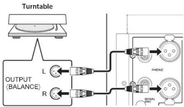
Balanced connection
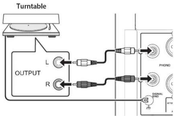
Unbalanced connection
Note
If you connect the turntable to the RCA jacks on this unit, listen to and compare the sound with the SIGNAL GND (ground) terminal connected and unconnected, and then select whichever less noisy.
NOTICE
Do not use balanced and unbalanced connections between this unit and the turntable simultaneously. Doing so would create a ground loop that could generate static and noise.
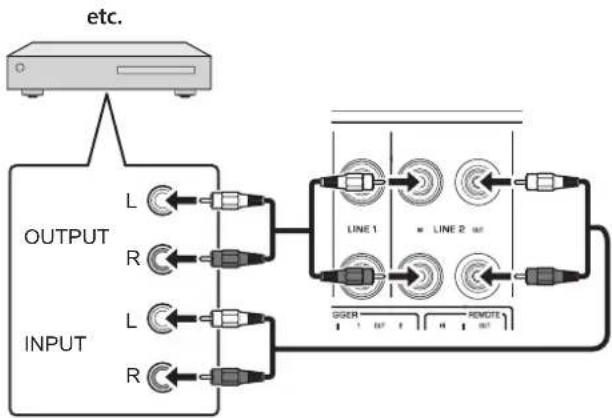
Connecting a recording component
You can connect a recording device, such as a hard disk recorder to the unit, and record audio input from the unit. Connect the recording component to both LINE 2 IN jacks and LINE 2 OUT (recording) jacks.
Note
Make sure that you connect the LINE 2 IN jacks and LINE 2 OUT (recording) jacks to the same component.
The signal from the LINE 2 OUT (recording) jacks is essentially identical to the signal from the output jacks specified by the OUTPUT selector. If the INPUT selector is set to LINE 2, no signal will be output at the LINE 2 OUT (recording) jacks.
Hard disk recorder,
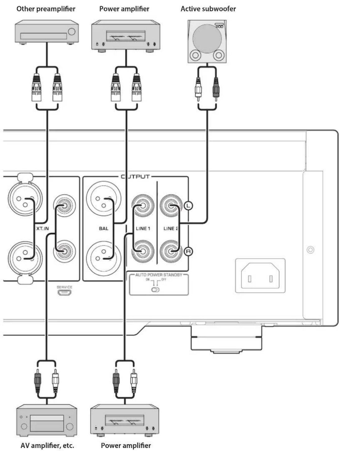
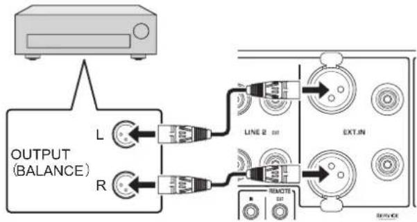
Connecting another preamplifier
If you connect the output of another preamplifier to the EXT. IN jacks on this unit and press the EXT. DIRECT switch, the source signal will pass through the unit and will be output to the connected power amplifier. The source signal input at the balanced EXT. IN jacks will be output at the balanced BAL jacks. The source signal input at the unbalanced EXT. IN jacks will be output at the LINE 1 and LINE 2 jacks.
Note
If the EXT. DIRECT switch is turned on, you will not hear any sound from the headphones connected to the PHONES jack.
Other preamplifier
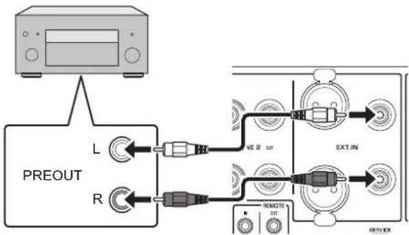
AV amplifier, etc.
Connecting a power amplifier and an active subwoofer
You can connect a power amplifier and an active subwoofer to the BAL, LINE 1, or LINE 2 output jacks on this unit.
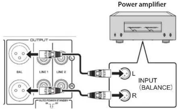
Balanced connection
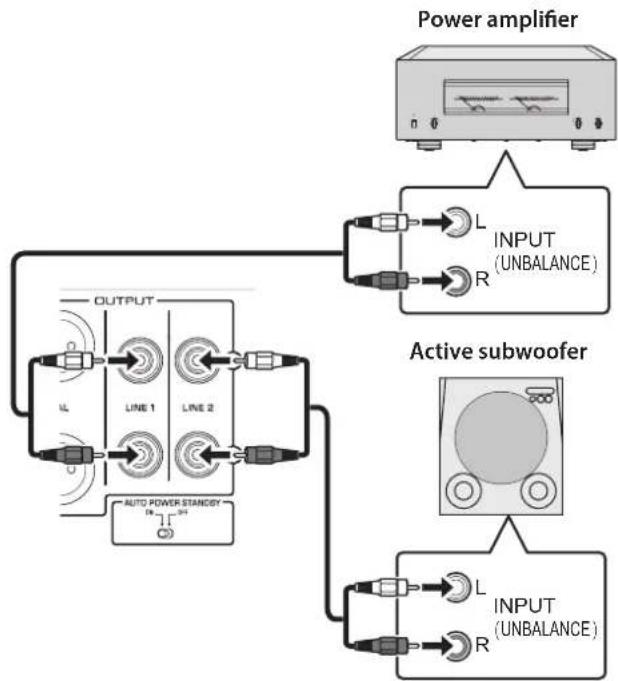
Unbalanced connection
NOTICE
Do not use balanced and unbalanced connections between two components simultaneously. Doing so would create a ground loop that could generate static and noise.
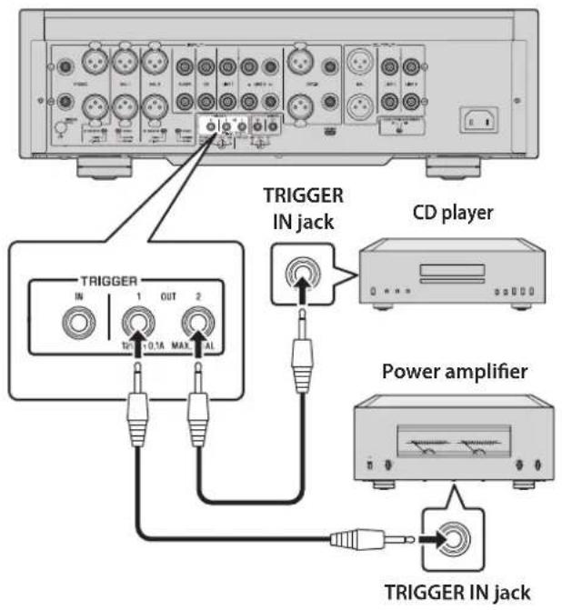
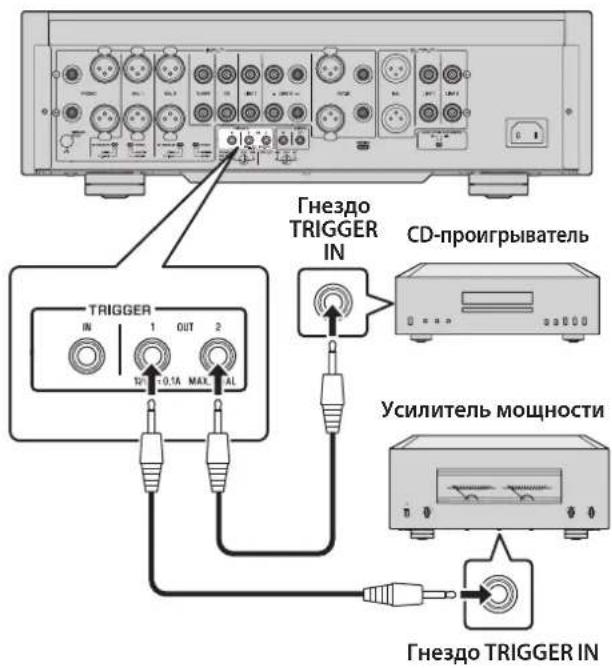
Trigger connections
Controlling the power on-and-off operation of a connected component, such as a power amplifier, in sync with this unit
You can control the power on-and-off operation of a connected component, such as a Yamaha CD player or power amplifier, in sync with this unit.
Use a system cable to connect the unit's TRIGGER OUT jack to the connected component's TRIGGER IN jack.
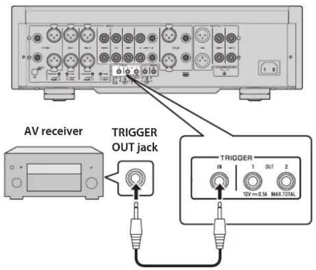
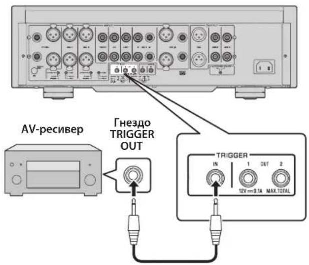
Controlling the unit's power on-and-off operation in sync with a connected component, such as an AV receiver
You can control the unit's power on-and-off operation in sync with a connected component, such as a Yamaha AV receiver. Use an optional system cable to connect the unit's TRIGGER IN jack to the connected component's TRIGGER OUT jack. While the unit is in standby mode, turning on the power to the connected component will also turn on the unit, and the signal at the EXT. IN jacks will be selected as the input source. When the power to the connected component is turned off, the unit will enter standby mode.
Note
If the power switch of this unit is turned OFF, power to the unit will not be triggered from a connected component.
Unless the input source is selected via the EXT. DIRECT switch, turning off the connected component will not turn off power to the unit.
Remote connections
Operating the unit from another room
If you connect an infrared receiver and transmitter to the unit's REMOTE IN/OUT jacks, you will be able to operate the unit and/or external component from another room, using the supplied remote control.
Remote connection between Yamaha components
If you have another Yamaha component that supports remote connections, as this unit does, an infrared transmitter is not necessary. You can transmit remote signals by connecting an infrared receiver to the unit's REMOTE IN jack, and the REMOTE IN jack of the other component to the unit's REMOTE OUT jack, using monaural mini-plug cables. Up to three Yamaha components (including this unit) can be set up for remote connection.
Infrared receiver
Infrared transmitter
Infrared receiver
Monaural mini-plug cable
REMOTE INOUT
Remote control
External component (CD player, etc.)
Remote control
Yamaha component (up to 3 components, including this unit)
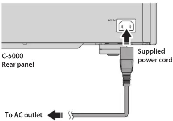
Connecting the power cord
After all connections are complete, make sure that the STANDBY/ON/OFF (Power) switch is turned off, then plug the power cord into the AC IN connector of the unit, and then plug the power cord into the AC outlet.

WARNING
If you notice any of the following abnormal conditions, turn off the power to the unit immediately, and disconnect the power plug from the AC outlet.
- The power cord or plug is damaged.
- The unit is emitting odor, strange noise, or smoke.
- Liquid has been spilled or objects have fallen into the unit.
- The sound is suddenly muted during operation.
- The unit is cracked or damaged.
Otherwise, continued use of the unit might lead to electric shock, fire, or malfunction. Contact your nearest Yamaha dealer or service center for check-up or repair.
- Do not touch the power cord or plug during lightning storms. Otherwise, an electric shock might be caused.
- Be sure to use a power outlet with the power voltage labeled on the unit. If the unit is plugged into an outlet of an inappropriate voltage, fire, electric shock, or malfunction might be caused.
- Use only the supplied power cord. Do not use the supplied power cord for other devices. Otherwise, fire, burning, or malfunction might be caused.
- Plug the unit into an AC outlet that is clearly visible and easily reached, so that you can unplug the unit easily and quickly from the AC outlet in case of emergency. Even when the power switch is turned off, a minimal amount of electric current is still flowing to the unit, unless you unplug the unit from the AC outlet.
If a lightning storm is approaching, turn off the power to the unit immediately, and disconnect the power plug from the AC outlet. Otherwise, fire or malfunction might be caused.
If you plan not to use the unit for an extended period of time, be sure to unplug the power cord from the AC outlet. Otherwise, fire or malfunction might be caused.

- Do not use an AC outlet that is so loose that the plug does not stay firmly in place. Otherwise, fire, electric shock, or burning might be caused.
- When disconnecting the power cord from the AC outlet, grasp the plug; do not pull the cord. Otherwise, the power cord might be damaged, causing an electric shock or fire.
- Insert the power plug into the AC outlet all the way firmly. If the plug is not inserted completely, use of the unit might cause an electric shock. Or, dust might build up on the plug, causing fire or burning.
NOTICE
If you plan not to use the unit for an extended period of time, be sure to unplug the power cord from the AC outlet. Even when the STANDBY/ON/OFF switch is turned off (the power indicator is dark), a minimal amount of electric current is still flowing to the unit.
Operations
This section explains basic operating procedures. You can follow these procedures to take advantage of the unit's functions. These procedures are intended only as examples.
Turning the power on

CAUTION
Be sure to lower the volume level to minimum before turning the power on.
Turn the power on by setting the STANDBY/ON/OFF (Power) switch on the front panel to STANDBY/ON.
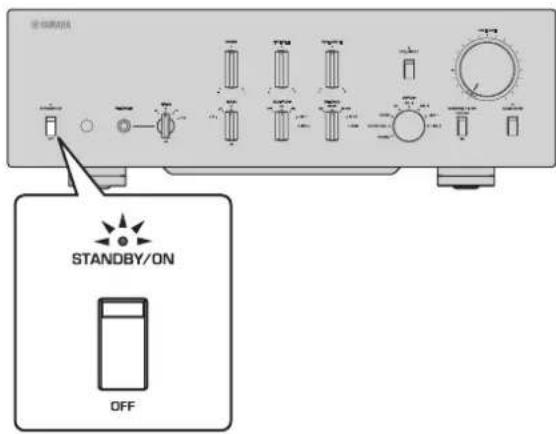
If the unit is in standby mode, you can also turn the power on using the remote control.
NOTICE
Turn on the power to all components in the following sequence: power amplifier, preamplifier (this unit), other components (such as a CD player and tuner).
Reverse this sequence when you turn the power off.
Selecting the input and output
Select a pair of output jacks using the OUTPUT selector.
Select the audio source using the INPUT selector.
The corresponding indicators will light up.
Selecting the input from the EXT.IN jacks
Press the EXT. DIRECT switch. The EXT. DIRECT indicator will light up. The INPUT selector setting will be disabled, and the audio source input from the EXT. IN jacks will be output at a pair of the output jacks. The source signal input at the balanced input jacks will be output at the balanced BAL output jacks. The source signal input at the LINE input jacks will be output at the LINE 1 and LINE 2 output jacks.
If you press the EXT. DIRECT switch again or rotate the INPUT selector, the signal specified by the INPUT selector will become the input source. The EXT. DIRECT indicator will turn off.
Note
If EXT. DIRECT is selected, no signal will be output at the LINE 2 OUT (recording) jacks nor at the PHONES jack.
Adjusting the turntable input setting
PHONO selector
Set the PHONO selector according to the turntable cartridge.
Options for turntable cartridge
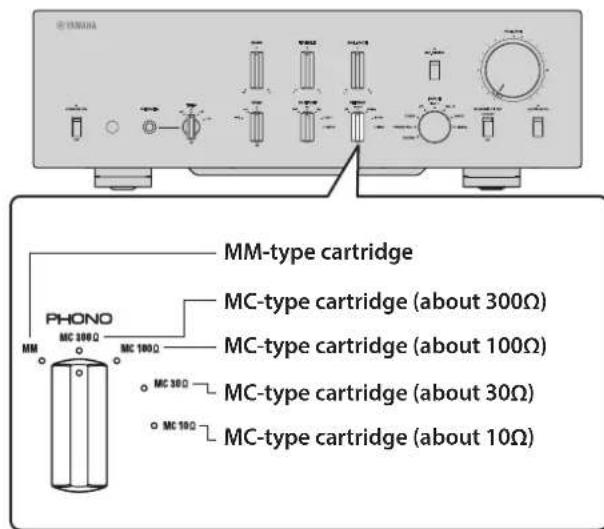

CAUTION
If an MM-type cartridge is used on the turntable, be sure to set the PHONO selector to MM.
Note
Impedance labels on the PHONO selector indicate approximate values. Listen to and check the sound with different impedance settings to select the most appropriate option.
NOTICE
Before you replace the cartridge, be sure to turn off the power to this unit.
Subsonic filter
Turn on the SUBSONIC FILTER switch to apply the subsonic filter, as needed.
A resonating turntable tone arm or a warped vinyl record could cause a very low frequency rumble (subsonic noise) that might apply load and damage to the speakers. A subsonic filter will cut such noise to protect the speakers.
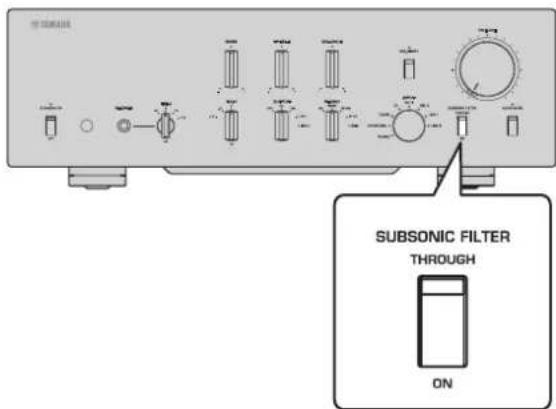
Note
The subsonic filter is disabled whenever any audio source other than the turntable (connected to the PHONO jacks) is selected as the input source, even if the SUBSONIC FILTER switch is turned on.
Adjusting the volume level
Set the gain using the GAIN selector so that you can make fine volume adjustments.
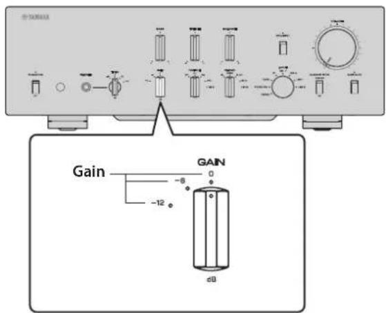
Adjust the volume level using the VOLUME control.
Note
If you still hear distortion even if the VOLUME control is turned down, the signal might exceed the allowable input level. If the audio source is being input at the balanced input jacks (BAL 1 or BAL 2), set the ATTENUATOR selector to ATT. (-6 dB).
Lowering the volume level momentarily
Press the AUDIO MUTE switch to reduce the current volume level by approximately 20 dB. Press the switch again to restore the previous volume level.
Adjusting the tone
Adjust the volume level balance between the left and right speakers using the BALANCE control.
Adjust the volume level of the high and low ranges using the BASS and TREBLE control.
Note
If both BASS and TREBLE controls are set to the center, the audio signal will bypass the tone control circuit.
- The BASS, TREBLE, and BALANCE control settings will not affect the input signals at the EXT. IN jacks nor the output signals at the LINE 2 OUT (recording) jacks.
Connecting headphones
If headphones are connected to the PHONES jack, no signal will be output at the output jacks (BAL, LINE 1, and LINE 2 output jacks) on the rear panel.

Use the TRIM selector to switch the headphone amp gain so you can adjust the level balance between the audio output from the PHONES jack and the speakers to avoid sudden changes in volume.
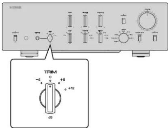
Note
If EXT. DIRECT is selected, no signal will be output from the PHONES jack.
Reference Materials
General specifications
Rated output voltage/output impedance (Input 200mV 20 Hz to 20 kHz, THD 0.01%
BAL (BYPASS). 2 Vrms/150Ω
BAL (ATT. -6dB) 1 Vrms/150Ω
LINE 1/LINE 2. 1 Vrms/150Ω
LINE 2 OUT (recording). . . . . . . . . . . . . . . . . . . . . . . . . . . . . . . . . . . . . . . . . . . . . . . . . . . . . . . . . . . . . . . . . . . . . . . . . . . . . . . . . . . .
Maximum output voltage (1 kHz, THD 0.05%)
BAL. 6 Vrms
LINE 1/LINE 2. 3 Vrms
LINE 2 OUT (recording). 3 Vrms
Input sensitivity/Input impedance
BAL/LINE 1/LINE 2, 1 V
BAL 1/BAL 2. .200 mVrms/52 kΩ
TUNER/CD/LINE 1/LINE 2 IN 200mVrms / 47k
EXT.IN. 1 Vrms/20 kΩ
LINE 2 OUT (recording) (150mV,1kHz)
PHONO (MC 300Ω) 100 μVrms/300Ω
PHONO (MC 100Ω) 100 μVrms/100Ω
PHONO (MC 30Ω) 100 μVrms/30Ω
PHONO (MC 10Ω) 100 μVrms/10Ω
PHONO (MM, XLR-type). 2.5 mVrms/52 kΩ
PHONO (MM, RCA-type) .2.5 mVrms/47 kΩ
Maximum input signal voltage LINE 2 OUT (recording) (1kHz, THD 0.05%)
BAL (BYPASS). 2.8 Vrms
BAL (ATT. -6dB) 5.6 Vrms
TUNER/CD/LINE 1/LINE 2 IN. 2.8 Vrms
PHONO (MC) 2 mVrms
PHONO (MM) 50 mVrms
EXT.IN 5.6 Vrms
Frequency response (JEITA, load 22 kΩ)
10 Hz to 100 kHz +0/-3 dB
20 Hz to 20 kHz +0/-0.3 dB
Total harmonic distortion plus noise (JEITA, input 0.5 V, 20 Hz to 20 kHz)
BAL 1/BAL 2/TUNER/CD/LINE 1/LINE 2 IN BAL/LINE 1/LINE 2 .0.0100%
PHONO (MC) LINE 2 OUT (recording) 0.0200%
PHONO (MM) LINE 2 OUT (recording) 0.0200%
Channel separation
(Input 1.0k terminated, 1kHz / 10kHz JEITA)
BAL 1/BAL 2/TUNER/CD/LINE 1/LINE 2 IN 110 dB or higher
PHONO (MC) 80 dB or higher
PHONO (MM) 98 dB or higher
Function separation
(IHF-A network, input 1.0 kΩ terminated, JEITA)
BAL 1/BAL 2/TUNER/CD/LINE 1/LINE 2 IN 110 dB or higher
PHONO (MC) 75 dB or higher
PHONO (MM) 95 dB or higher
Signal to noise ratio
(IHF-A network, input 1.0k terminated, JEITA)
BAL 1/BAL 2/TUNER/CD/LINE 1/LINE 2 IN 110 dB or higher
PHONO (MC 300Ω) .80 dB or higher
PHONO (MM) 98 dB or higher
Residual noise (IHF-A network)
BAL/LINE 1/LINE 2 3 V
Tone control characteristics
Bass Boost/cut 30 Hz/±9 dB Turnover frequency 350 Hz
Treble Boost/cut 20 kHz/±9 dB
Turnover frequency 3.5 kHz
Headphone jack rated output power
(1 kHz, 32Ω, 0.2% THD)
35mW+35mW
RIAA equalization deviation
MC/MM ± 0.5 dB
Subsonic filter characteristics
MC/MM 15 Hz/-3 dB
Power supply
[Models for U.S.A. and Canada]. .AC 120 V, 60 Hz
[Model for China] .AC 220 V,50 Hz
[Model for Korea] .AC 220 V,60 Hz
[Model for Australia]. AC 240 V, 50 Hz
[Models for U.K. and Europe] .AC 230 V,50 Hz
[Model for Asia] . . . AC 220-240 V, 50Hz / 60Hz
[Models for Central and South America,
and Taiwan] .AC 110 V,60 Hz
Power consumption
60W
Standby power consumption
Off mode. 0.1 W
Standby mode 0.2 W
Dimensions (W× H× D)
435× 142× 451mm
Weight
19.1 kg
- The contents of this manual apply to the latest specifications as of the publishing date. To obtain the latest manual, access the Yamaha website then download the manual file.
Block diagram
Audio characteristics
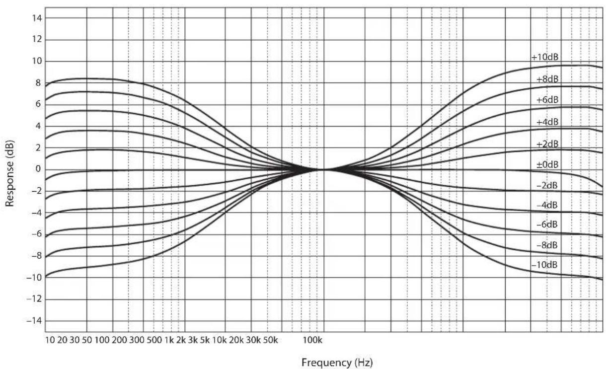
Frequency response (tone control)

Total harmonic distortion (PHONO)
Frequency response (subsonic filter)

Volume curve

Troubleshooting
Refer to the table below if this unit does not function properly. If the instructions below do not help, or if the problem you are experiencing is not listed below, turn off the unit, disconnect the power cord, and contact the nearest authorized Yamaha dealer or service center.
| Problem Cause Remedy | See page | ||
| Power does not turn on. | The power cord is not connected to the AC IN connector on the rear panel or is not plugged into an AC outlet. | Connect the power cord firmly. 26 | |
| The unit has been exposed to a strong external electric shock (such as lightning or strong static electricity). | Turn off the unit, disconnect the power cord from the AC outlet, wait for about 30 seconds, and then plug the unit in again. | 26 | |
| There is a problem with the internal circuitries of this unit. | Disconnect the power cord from the AC outlet and contact the nearest authorized Yamaha dealer or service center. | 26 | |
| No sound is heard. | Incorrect input or output cable connections. | Connect the cables properly. If the problem persists, the cables might be defective. | 20 |
| No appropriate input source has been selected. | Select an appropriate input source using the INPUT selector on the front panel (or one of the input selector keys on the remote control). | 28 | |
| The OUTPUT selector setting does not match the output jacks that are being used. | Select an appropriate output using the OUTPUT selector. | 28 | |
| The volume level cannot be adjusted. | EXT. DIRECT is selected as the input source. | Adjust the volume level on the connected component. Alternatively, connect the external component to a pair of the input jacks other than the EXT. IN jacks, and then select the corresponding input source. | 20 28 |
| Only one channel speaker can be heard. | The playback component is not connected properly. | Make sure that the connections are made properly. If the problem persists, the cables might be defective. | 20 |
| Problem Cause Remedy | See page | ||
| A "humming" noise is heard. | Incorrect input or output cable connections. | Connect the cables properly. If the problem persists, the cables might be defective. | 20 |
| The turntable is not grounded to the GND terminal. | Connect the turntable to the GND terminal of this unit. | 22 | |
| Both balanced and line cables are being used simultaneously between two components. | Do not use both balanced and line cables simultaneously between two components. Doing so would create a ground loop that could generate static and noise. | 21 | |
| Playback audio from the component connected to the BAL 1 or BAL 2 balanced input jacks sounds distorted. | The level of the signal at the balanced input jacks is exceeding the allowable input level. | If the level of the signal at the XLR-type balanced output jacks on the connected playback component is doubled compared to the RCA unbalanced jacks, set the ATTENUATOR selector located below the input jacks to ATT. (-6 dB). | 30 |
| Bass lacks depth when BAL 1 or BAL 2 (balanced input) is selected. | The polarity is incorrect. | Select the correct polarity using the PHASE selector. | 14 |
| The volume level of the vinyl record is too low. | The PHONO switch on the front panel is set incorrectly. | Set the PHONO switch to the MM or MC position according to the type of magnetic cartridge of the turntable. | 29 |
| The remote control does not work or function properly. | The remote control has been used out of the operating range. | The remote control must be used within a maximum distance of 6 m and no more than 30 degrees off-axis from the remote control sensor on the front panel. | 18 |
| Direct sunlight or lighting (from an inverter type of fluorescent lamp, strobe light, etc.) is hitting the remote control sensor on the front panel. | Change the orientation of the lighting or reposition the unit. | 18 | |
| The batteries are weak. Replace all batteries. 18 | |||
Index
A
AC IN jack 26
Adjusting the turntable input 29
ATTENUATOR selector 30
AUDIO MUTE switch 31
AUTO POWER STANDBY switch 13
B
BAL1jack. 11
BAL 2 jack. 11
BALANCE control 31
Balanced connection 14
BAL jack 13
BASS control 31
C
Connecting a power amplifier 23
Connecting a recording component 22
Connecting a subwoofer 23
Connecting a turntable 22
Connecting headphones 32
E
EXT.DIRECT switch 29
External In jack 23
EXT.IN jack 23
G
GAIN selector 30
Ground terminal 22
1
INPUT selector 28
L
LINE 1 jack 13
LINE 2 jack 13
LINE 2 IN jack 12
LINE 2 OUT (recording) jack 12
0
OUTPUT selector 28
P
PHASE selector 14
PHONES jack 32
Phono jack 22
PHONO jack 22
PHONO selector 29
Power indicator 6
Power switch 6
R
Remote connection 25
Remote control sensor 18
REMOTE jack 25
S
SERVICE jack 13
SIGNAL GND terminal 22
Signal ground terminal 22
STANDBY/ON/OFF indicator 6
STANDBY/ON/OFF switch 6
SUBSONIC FILTER 30
SUBSONIC FILTER switch 30
T
TREBLE control 31
Trigger connection 24
TRIGGER jack 24
TRIM selector 32
Turning the power on 6
U
Unbalanced connection 15
V
VOLUME control 30
https://download.yamaha.com/
Fonctions
Prises REMOTE IN/REMOTE OUT
BAL (BYPASS). 2 Vrms/150Ω
BAL (ATT. -6dB) 1 Vrms/150Ω
LINE 1/LINE 2. 1 Vrms/150Ω
LINE 2 OUT (enregistrement) . . 200mVrms / 1,2k
EXT.IN. 1 Vrms/20 kΩ
LINE 2 OUT (enregistrement) (150mV,1kHz)
PHONO (MC 300Ω) 100 μVrms/300Ω
PHONO (MC 100Ω) 100 μVrms/100Ω
PHONO (MC 30Ω) 100 μVrms/30Ω
PHONO (MC 10Ω) 100 μVrms/10Ω
PHONO (MM, type XLR) 2,5 mVrms/52 kΩ
PHONO (MM, type RCA). 2,5 mVrms/47 kΩ
Accentuation/attenuation. 30 Hz/±9 dB
Accentuation/attenuation. 20 kHz/±9 dB
Buchsen REMOTE IN/REMOTE OUT
BAL (BYPASS). 2 Vrms/150Ω
BAL (ATT. -6dB) 1 Vrms/150Ω
LINE 1/LINE 2. 1 Vrms/150Ω
LINE 2 OUT (Aufnahme) . . . . . . . . . . . . . . . . . . . . . . . . . . . . . . . . . . . . . . . . . . . . . . . . . . . . . . . . . . . . . . . . . . . . . . . . . . . . . . . . . . . .
EXT.IN. 1 Vrms/20 kΩ
PHONO (MC 100Ω) 100 μVrms/100Ω
PHONO (MC 30Ω) 100 μVrms/30Ω
PHONO (MC 10Ω) 100 μVrms/10Ω
PHONO (MM, XLR). 2.5 mV rms/52 kΩ
PHONO (MM, Cinch) 2.5 mV rms/47 kΩ
https://download.yamaha.com/
Funktioner
REMOTE IN/REMOTE OUT-uttag
Dessa ar mono-minikontakter. Anslut externakomponenter som stoder triggerfungtionen har. For merinformation, sc "Fjarransluttingar" (sidan 145).

SERVICE-uttag
BAL (BYPASS). 2 Vrms/150Ω
BAL (ATT. -6dB) 1 Vrms/150Ω
LINE 1/LINE 2 . 1 Vrms/150Ω
LINE 2 OUT (inspelning) . . . . . . . . . . . . . . . . . . . . . . . . . . . . . . . . . . . . . . . . . . . . . . . . . . . . . . . . . . . . . . . . . . . . . . . . . . . . . . . . . . .
Maximal utgangsspanning (1 kHz, THD 0,05%)
BAL. 6 Vrms
LINE 1/LINE 2. 3 Vrms
EXT.IN. 1 Vrms/20 kΩ
LINE 2 OUT (inspelning) (150mV,1kHz)
PHONO (MC 300Ω) 100 μVrms/300Ω
PHONO (MC 100Ω) 100 μVrms/100Ω
PHONO (MC 30Ω) 100 μVrms/30Ω
PHONO (MC 10Ω) 100 μVrms/10Ω
PHONO (MM, XLR-typ) 2,5 mVrms/52 kΩ
PHONO (MM, RCA-typ) 2,5 mVrms/47 kΩ
Maximal ingängssignal for spanning
LINE 2 OUT (inspelninq) (1kHz, THD 0,05%)
BAL (BYPASS). 2,8 Vrms
BAL (ATT. -6dB) 5,6 Vrms
TUNER/CD/LINE 1/LINE 2 IN. 2,8 Vrms
PHONO (MC) 2 mVrms
PHONO (MM) 50 mVrms
EXT.IN 5,6 Vrms
Frekvensætergivning (JEITA, belastning 22 kΩ)
10 Hz till 100 kHz. +0/-3 dB
20 Hz till 20 kHz. +0 / - 0,3 dB
Total harmonisk distorsion + brus
https://download.yamaha.com/
Caratteristiche
Specifications of the system are given in Table 1.
Prese REMOTE IN/REMOTE OUT
BAL (BYPASS). 2 Vrms/150Ω
BAL (ATT. -6dB) 1 Vrms/150Ω
LINE 1/LINE 2. 1 Vrms/150Ω
LINE 2 OUT (registratione) . . . 200 mVrms/1,2 kΩ
EXT.IN. 1 Vrms/20 kΩ
PHONO (MC 100Ω) 100 μVrms/100Ω
PHONO (MC 30Ω) 100 μVrms/30Ω
PHONO (MC 10Ω) 100 μVrms/10Ω
PHONO (MM, tipo XLR) . . . 2,5 mVrms/52 kΩ
PHONO (MM, tipo RCA) . . . 2,5 mVrms/47 kΩ
Rumore residuo (rete IHF-A)
BAL/LINE 1/LINE 2 3 V
https://download.yamaha.com/
Funciones
Interruptor/indicator AUDIO MUTE
Jacks REMOTE IN/REMOTE OUT
BAL (BYPASS). 2 Vrms/150 Ω
BAL (ATT. -6dB) 1 Vrms/150 Ω
LINE 1/LINE 2 . 1 Vrms/150 Ω
LINE 2 OUT (grabacion) . . . . . . . . . . . . . . . . . . . . . . . . . . . . . . . . . . . . . . . . . . . . . . . . . . . . . . . . . . . . . . . . . . . . . . . . . . . . . . . . . . .
EXT.IN. 1 Vrms/20 kΩ
LINE 2 OUT (grabacion) (150mV,1kHz)
PHONO (MC 300 Ω) 100 μVrms/300 Ω
PHONO (MC 100 Ω). 100 μVrms/100 Ω
PHONO (MC 30 Ω) 100 μVrms/30 Ω
PHONO (MC 10Ω) .100 Vrms / 10
PHONO (MM, tipo XLR) . . . 2,5 mVrms/52 kΩ
PHONO (MM, tipo RCA) . . . 2,5 mVrms/47 kΩ
https://download.yamaha.com/
Eigenschappen
NORMAL: Pin #2 is HOT.
BAL (BYPASS). 2 Vrms/150Ω
BAL (ATT. -6dB) 1 Vrms/150Ω
LINE 1/LINE 2. 1 Vrms/150Ω
LINE 2 OUT (opname) . . . . . . . . . . . . . . . . . . . . . . . . . . . . . . . . . . . . . . . . . . . . . . . . . . . . . . . . . . . . . . . . . . . . . . . . . . . . . . . . . . . . . .
EXT.IN. 1 Vrms/20 kΩ
LINE 2 OUT (opname) (150mV,1kHz)
PHONO (MC 300Ω) 100 μVrms/300Ω
PHONO (MC 100Ω) 100 μVrms/100Ω
PHONO (MC 30Ω) 100 μVrms/30Ω
PHONO (MC 10Ω) 100 μVrms/10Ω
PHONO (MM, XLR-type). 2,5 mVrms/52 kΩ
PHONO (MM, RCA-type) 2,5 mVrms/47 kΩ
Maximaal spanning ingangssignaal LINE 2 OUT (opname) (1kHz, THD 0,05%
BAL (BYPASS). 2,8 Vrms
BAL (ATT. -6dB) 5,6 Vrms
TUNER/CD/LINE 1/LINE 2 IN. 2,8 Vrms
PHONO (MC) 2 mVrms
PHONO (MM) 50 mVrms
EXT.IN 5,6 Vrms
Frequentierresponse (JEITA, belasting 22k
10 Hz tot 100 kHz. +0/-3 dB
20 Hz tot 20 kHz. +0 / - 0,3 dB
Totale harmonische verrorming met ruis (JEITA, ingang 0,5 V, 20 Hz tot 20 kHz)
BAL 1/BAL 2/TUNER/CD/LINE 1/LINE 2 IN BAL/LINE 1/LINE 2 .0,0100%
PHONO (MC) LINE 2 OUT (opname) 0,0200%
PHONO (MM) LINE 2 OUT (opname) 0,0200%
Kanaalscheiding
(ingang 1,0 kΩ terminated, 1 kHz/10 kHz, JEITA)
BAL 1/BAL 2/TUNER/CD/LINE 1/LINE 2 IN 110 dB of hoger
PHONO (MC) 80 dB of hoger
PHONO (MM) 98 dB of hoger
Functiescheiding
(IHF-A network, ingang 1,0 kΩ terminated, JEITA)
BAL 1/BAL 2/TUNER/CD/LINE 1/LINE 2 IN 110 dB of hoger
PHONO (MC) 75 dB of hoger
PHONO (MM) 95 dB of hogcr
https://download.yamaha.com/
Функцин
CmmMeTpHbI d3aH cIeBa H cnpaba co3daet ctpyKtypy BcIOuKy
IpeJaHaIIOHOrIO IIaBaHOIIeRo cHMMETpHNoHOrO cHrHaJa KlaCca A OT BBOJa IO BBBOJa
YCHJHTeJIb IIaBAIOIeTO CHMMETpHcHOrO 0HO3KB aJIaII3epa C cHMMeTpHbIMN BXoJaMn
BbICOKOTOHTHbe 3JIeMeHTbI yIpaBJIeHHa OCHOBEΦnPMeHHoI OIIOPHOI KOHCTpyKUHN C JkecTKHM pbluaJHKbIMN IpeKJIIOuHaTEJIaMNI
CBoeHHbI Ipeo6pa3OBeJIb, pa3pa6oTaHHbI cIIeIIHaJIbHO IIa ayIOHcIHHaJIbO, KOtOpbI IOJIHOCTbIO OTJeIEH OT KOHTPOJIbHO HcTOUHnKa IITaHH
YcToHnBaMEXaHHueckKa KOHCTpyKIIIOOCHOBAHN 3HaHTeJIbHO yMcHbIIaET BIIHHeBHEIIHHx B6paIIN
KoHTyp peRyIINPOBKN TeM6pa c npMeHHoH chTeMoH npaJIeJIbHO rPOMKOCTbIO
HOBBI IN3aHIOKEK B BNIE MeINbIX INHIOB
ΦyHKnHa KOHTpOJI ycHJIeHHa, KOTopaa IIO3BOJAAET BbIIOJIHrTb CBePXTOHKyHO HAcTpOaHy rPoMKOCTH
O daHHOM pyKOBODCTBe
HIIIOCTpaHINBJaHHOMpyKOBOCTBEIpeIDaJIeHbTOJIbKO B O3HaKOMHTeJIbHbIXIeJHX.
Ha3BaHHaKOMIIaHHI IpoJyKTOB BYKOBOCTBE ABJIIOCTe TOBapHbIMN 3HaKaAMn HIN 3apeHCTpHPOBAHHbIMN TOBapHbIMN 3HaKaAMn HX COOTBcTCTBYIOHN BlaJeJIbueB.
"! I PEPDyPEXKDEHNE" 6o3Haayet MepyI PpeIOCTOpOxHOCTN, KOToPbIE cJeIyET CO6JIHOaTb,HTo6bI H36eKaTb pNcKa CMEPTN HIN CEpb3HOJ TpaBMbl.
BHUMAHUE" 06o3Haayet Mepy IpeIOcTOPOKHOCTH, KOToPbIe cJIeIyET co6JIIOHaTb, YTO6bI H36eKaTb pHcKa TpaBMbl.
"YBEDOMJHEHNE" 063Haayet Mepy IpeocTopoXHOCTH, KOToPbIe CJIeIyET CO6IOaTb, YTO6bI H36eKaTb PnCKa HeNCpAABHOCTH HIN IOBpeKJeEHNII pOlykTa HIN DaHHbIX.
"PpimmeaHne" 063HaaeT IOIOJIHHTeIbHyIO HhOpaMauHIO o IpoDyKte.
IpeCn HauaIOM HcIOJIb3OBAHnI npOyKTA 68aTeJIbHO O3HaKOMbTecb C OTJeJIbHO 6poIHOpo N0 6e3OIIacHOCTH.
Copepkne
Функции 282
O daHOM pyKOBOdCTBe 282
IocTabnemble akceccyapbl 284
TexHnueeckoe 6cbnyKuBaHne 284
Bokobbie nHaHei c 3epKaJIbHbIM NOKpbITnem. 284
PObepxHocTN,OTnHbIeOT6OKOBbIX naHei e 3epKaJIbHbIM NOKpbITnem . . . 284
Ha3BaHnKa KomnoHEtOB n nx yHKcnn
PepednnaHb. 286
3aHnaHelb 290
CmmMeTpUHbIe HecMMMeTpUHbIe coeHHHeH. 294
PnybT Dy 296
UcTaHOBka 6aTapeek B nIyIbT dY. . . . . . 298
UnpaBneHc nOmoIyIyIy...298
PoiKIOUeHnIa
IopKIOUeHne BHeuHero KOMnOHeHTa . 300
IopknueHn npounpbiBateJ 302
IopKIOUeHHe 3aINcBIAUoJero KOMNoHEHTa . 302
IopknueHne npyroro npeducnntela.303
IoiKIOUeHHe ycINTEeMa MOUHOCTn n aKTHBHorO ca6Byepepa 303
TpurrepHbIe coeINHeHHa. 304
YnpaBHeNe OepaueN BkIoueHn I
BbIKIOUeHn NITaHn NOKIIIOUeHHOrO
KOMNoHEtA,HaNPmEp,ycNJInTeJr
MOuHOCTu,CINxPOHNO C daHHbIM
annapaTOM 304
UnpaBHeHne Oepauee BkIoueHn I
BbIKIOueHn NITaHn aIInapaTa CnHXPOHHO
C NOKIOUeHHbIM KOMNOHEHTOM,
Haipmep, AV-pecNBepom 304
IuctaHcnoHHbIe coeHNHeHn. 305
UnpaBHeHne annapaTOM n3 npyroKOMHaTbI. 305
Bb6op BxOda n BblXoDa 308
Bb6op BXoHoro CnHaHa n3 rHe3dEXT.IN 309
Hactpoika BXOdHoro cnHana npounpblBaTeIa 309
Cenektop PHONO. 309
HΦpa3ByKOBoi ΦnIbTp 310
HacpoKa ypOBHr pOMKoCTn 310
MrHOBeHHoe yMeHbUeHne yPoBHa rPOMKoCTn 311
HactpoIka Tem6pa 311
IopKnIOueHne HayuHnKOB 312
CnpaBoHbI MaTePnAbI
06uueTexHnueckne xapaKtepncnK..314
BloK-cxema. 316
XapakTepeNCTKnyaydnocnHa .317
YachToTHaXapaKTepeNCTnKa (perylnpoBk TaM6pa). 317
Ko3ΦΦnueHT HeHnHeuHbIX NcKaJKeHn (PHONO). 317
HΦpa3ByKOB0 ΦJIbTp 318
Kpmbar rpoMkoCTn 318
Bo3MOxHbIe HeNCpPaBHOCTn n CnOc6blnx yCtpaHeHra. 319
yka3aTeIb. 321
Poctablaemble akceccyapbl
Y6eHTecb, yTO CJIyIOHne AKCECCyapbI BXOJrT B KOMJIeKT HOCTABKN.
Iyntdy
Batapei(AAA,RO3,UM-4)(x2)
CunIOB0Ka6eIb
- INHCTpykua no EKcnnyatau (daHHa KnHa)
Bpouopa no 6e3onachoctn (Otehblb6yknet)

PNEyPExKdEHne
He nCnoNb3yIte npunaeraembi cnIOBo Kabebn dIpynx yctpoCTB.
TexHnueckoe 6cIyXnBaHne
TTO6bI HIOJIb3OBaTB DAHHbI IPOyKT B TeueHHe DINTeJIbHO BpemeHN, peKOMEHdyETcpeYJnPHO IIPOBOIDHTBTEXIIHueCKOE 06ClyKHBaHHe.

PNEyPExKDeHne
- PeryIaHIO npOBepaIte cINIOBoi Ka6eIb Ha HAIuHne HA HeM NbIi. B Clyuae cKoJIeHnI PbIi NOIHocTbIO COtpTe ee. B npOTNBOM Cnyuae 3TO MOKeT pNIBcTNI K NOXApY IINI NOPaKeHnIO 3JNEKTpUcckm TOKOM.
He nCnoB3yIe IJn OUHCTKn IIN CMA3Kn a3pO30JI INn cnpen, codepxauine ropuue ra3bl. B npTUBOM cnUae ropuynrA3 MOXET CKONITBCR BHTPN annapaTa, YTO MOXET pNBECTN K B3pbBy INn NOXAPy.
YBEDOMJIEHNE
- Iy nctkn annapata noh3yntecb mKo cyxoh TkaHbU. NcnoIb3ObaHne MOIOUX cpeCTB, TaKIN Kk 6eH3nH nn pa36aHTeJb, YnCTaue CpeCTBO nIIN o6pa6oTahHna XmMnueckncoCTabOM TkaHb, MoKET Bb3BaTb N3MeHeHne UBeTA nn NOBpeXdHne NOBepXHOCTn. PnCnblHom 3arpa3HeHn NOBepXHOCTu YBlaXHNTe TkaHb NcCTAum CpeCTBOM (pa3BeDeHHbM BOIo), TuaTeJIbHO OTOXMITE TkaHb N BbITPnte pRzB.
- Pn ycnneHHom npotnpaHm NOBepxHOCTN B 06naCTn IOROTnA Yamaha IOROTn MOKet OTKneTbCra NIN BOJOKHa OT TKAHN MOrYT pnnnHyTB K NOBEPXHOCTN.
Бokobbie панелс зеркальн biom nOKpbITnem
PekomeHyetyerHcIOJIb3OaBtBuHCTIyIO caIfoKy, aHAIOTnHyIO caIfoKAM IINI FOptEINHO. EcINIOBepxHOCTb OHHe rpa3Ha, HcIOJIb3yIte MmTKyIO yBIAJKeHHyIO BOIOH TIIATeJIbHO OTKaTyo TKaHB.
PobepxhoCTn,OTmHbIe OT 6OKOBbIX nHeJe C 3epKaJIbHbIM NOKpbITNeM
IpoTHpaHte ocTaJIbHbIE IOBepxHOCTM MrgKoI cyXOITKaHbIO. Ipn CnJIbHOM 3aIrpA3HCHNIOBcpxHOCTN yBIAJXHTe TKAHb HCTTtMM CpeCTBOM, pa3BeJeHHbIM BOIOI, TIIaTeJIbHO OTOXMITE KAHb H COPTHe Tpr3b C IOBepxHOCTN.
Ha3BaHnKOMNoHcHTOB nnx yHKcnn
B daHHOM pa3JeIe IpeIcTaBJIeHbI Ha3BaHnI n yHKIIIN pa3JIuHbIX KOMIOHETOB Ha nepeIHeN 3aJHeN IaHeN IN nyJIbTe DY.
Передна панель

NATURAL SOUND PRE-AMPLIFIER C-6000
1 NepeknioaTeNb/mHnkaTOp STANDBY/ON/OFF (NtTaHne)
BkIOueHHe (peKHMoeOKNJaHHN) HIN BbIKIOueHHe HHTaHHn aHnapata.
STANDBY/ON: IpeKIOHoeHne MEKdy BKOHOeHHbIM peKHMOM H pcKHMOM OKNJaHHc C IOMOIIbIO KHONK AMP Ha IIyIbTe IV.
OFF: BBKIOUCHHC INTATINH aIIIapapaTa.
| Состаянке ритань Идмкатор | |
| Вълочеву Горот ярко | |
| Рекиме ожUIDань Горот Тугково | |
| Вълочеву Н Горот | |
AIIIapat IpepeIeT BpeKHM OxHdAHn Hc ToJIbKO IIpHn HaKaTHn HA KHOIKy AMP Ha IIyJIbTe JY, HO H B OJHOM H3 CJIeDyIOHnx CJIyuaeB:
Bo3MOxHbIe 3NaueHnA: -6 nB,0 nB,+6 nB,+12 nB
5 CeIeKTop GAIN
IpeKIOHHe yCHIEHHI pCycHHTeJI. AIIapat IIABHO aIaITnpyTeK yChIEHHIO yCHHTeJI MOUHOCTN H CYBCTBHTeJIbHOCTN KOJOHOK, YTO IO3BOJIeT BIIIOJIHTb TOIKyIO HAcTPOIky IpOMKOCTN. IIO.IpO6He cM.Bpa3Je "HaCtpoiKa yPoBHr IpOMKOCTN" (ctp. 310).
Bo3MOxHbIe 3HaueHHa: -12B, -6B, 0B
6 CejekTop OUTPUT
OnpeJeHHe rHe3I OUTPUT,pee3 KOTopbIe BBIOJrTc nHHaJIb, cCJyIOIHm 6pa3OM.
HcIOJIb3yIe TaHHbI cJIeKTop IINHn HCCKOJIbKHX IOIKIIIOHcHHbIX YCHITCEJMe MOIHOCTH.
YctaHOBe TceNekTop ATTENUATOR n ceneKTop PHASE B noNoXeHne, COOTBeCTbIooJIe KOMnOHeHTam Bocnpoun3BedeHn, KOToPbIe NOkIIIOUeHb KannapaTy.
4 Cenektop ATTENUATOR
I03BOJIaTe yCTaHaBINbATb IOnyCTHMbI yPoBeHb BXOJHOrO cHHaJIa IJIa CMMETpHbIX BXoIHbIX rHe3I TIIa XLR (rHe3I BAL 1 n BAL 2).IIOJpo6Hee cm. B pa3JeIe "HacTPOIIka yPoBHra rPOMKocTH" (cTp. 310).
BYPASSIOnyctHMBI yPOCBH BXOHHORO cHTHaJIa Hc H3MeHITcR. B 06bHuHx ycIOBHX CJIeNyET BbIbHpTa bHaHoe 3HaueHHe.
ATT.(-6b):BXOHOe yCHJIeHHe 6yET CHHXKeHO Ha 6 b,TO6bI IIOHNrT BoNcyCTHMbI yPOBeHb BXOHOrO CnHrHaJIa.Bb6epHTe JAnHoe 3HaueHne, ECIN ayIOHCnHJIa, BbIOHMbI H3 IOKHOeHHORo KOMIOHEHTA,3ByHT NCKaKeHHO.
CenekTop PHASE
OnpceJnEETIOJOKeHHe KOHTaKaTc HOIT nI
CHMMETPHHBIX BXOINbIX THe3TnIIa XLR (rHe3BAL1 H BAL2).
NORMAL: KOHTAKT #2 BBi6paH B KaCCTBC KOHTAKTA HOT.
INV: KOHTaKT #3 BbI6paH B KauEcTBe KOHTaKTa HOT.
Piap06Hee cm. B pa3JeIe "CmmMetpHnHbe H
HecmmetpHnHbe coeHHcHn" (ctp. 294).
6 THe3daTUNER
3TO BXOJIHbIe THe3Ha RCA. Eecn ccKeTOp INPUT yCTaHOBJIeH BIOJOKeHHe TUNER, CHTHaJIbI, BBOIMMbIe uepe3 3TH THe3Ha, 6yDyT HcTOUHKOM BXOJHOrO CHTHaJIa. IIOKIIIOOHTE K Hm TIOheP.
3aHЯ paHeIb
7 THe3da CD
TO BxOJIHbIe rHe3Ja RCA.EcIN ceJIeKToP INPUT yCTAHOBJIeB HIOJOKeHHe CD, CHTHaJIbI, BBOJHMbIE Chepe3 OTH THe3Ja, 6yUT HCTOCHKO BxOJHOrO CHTHaJIa. IIOJKIOUHTe K HUM CD-IPONHPbBaTeJIb.
8 THe3da LINE 1
TO BXOHNIE THe3JA RCA. Ecn CEJIeKTop INPUT yctaHOBcH BIOIOKeHHc LINE 1, cHrHaJIb, BBOHMbc Hepe3 OTN THe3Jia, bYdT NCTOCHNKOM BXoHOrO CnHJaIa.
9 THe3da LINE 2 IN
TO BxOIIHbE IHe3Ja RCA. EcJIn ceJIeKTop INPUT YcTaHOBJIeH BIOJOKeHne LINE 2, 3TN IHe3Ja 6yIyT HCTOCHIKOM BXOJHORO CHHaJIa.
10 The3da LINE 2 OUT (3aanncb)
3TO BXOJIHbIC rHc3Ja RCA IINI 3aHHn. YpeC3 HIX
06bHIHO BbIOBHTC8 CHTHaJIbI HCTOCHKa BXOJHO
CHHaJIa, BbIbpaHHbc C IIMOIIbIO IIpcIHcN IaHcIJ INI
HJbTa IV. IHfOpMaIIHIO O IIpoJeIype IIOIKIOHeHN
CM.B pa3DeIe "IIOIKIOHeHne 3aHHcbIbAIooIEr
KOMIOHEHTa" (ctp. 302).
PpMueaHne
IopKJIIOHTe rHe3da LINE 2 IN u rHe3da LINE 2 OUT (aINCb) K ODNHY KOMNoHeHTy.
- The LINE 2 OUT (3a) He 6ydt BbOuHb CmHaBc, ecn ceneKTop INPUT yctaHOBneB nolooHe LINE 2 HxHkat nepeKnIOATEbEXT.DIRECT.
1 ένειδησις EXT.IN
Tn H3Ia HMeIOT XapaKTepeHCTKN BxOJIbIX THe3I
TIHa XL R IN BXoIHbIX THe3RCA.EJIN HAKaT
IpeKIOuATEJB EXT.DIRECT,CHTHaJI,IEpeJaBaembe
Yepe3 3TH THe3Ia,6yDyT HcTOHkOM BXoHOrO cHHaJa.
PiokIOOHTC K Hm IpcYcHITcIb.IoIp06Hcc cm.
B pa3JeIe "PiokIOUeHne npyToI ppeUcHITeJIA" (ctp. 303).

BHIMAHNE
HeBo3MOxHO HaCTpaNBaTb yPoBeHb rPOMKoCTn CnHaNoB, BBOIMMbIX uepe3 rHe3da EXT. IN. NToTOMy 063aTeNbHO nOdkIOHTe K rHe3dAmEXT. IN KOMnoHEr, KOtOpBm IMeet YHKUO ynpabNeHHrPOMKoCTbHO.
PpMueaHne
YpOBeHb rPOMKoCTn RbIaTeC TcNkCuPobAHbIM.
HcNoIb3OBaHne peryIaTopa VOLUME nnn ceneKToPA
GAIN Ha annapaTe He nImeHHT ypOBeHb rPOMKoCTn
CirHaJa, BBOdMOrO YpeE3rHe3daEXT.IN. OTperyIuPyIte
ypOBeHb rPOMKoCTn C NOMOuBIO peryIaTopa rPOMKoCTn Ha
KOMNoHEHe, NOdKIOUeHHOM KrHe3dAM EXT.IN.

THe3da BAL
TO BxOHNbIe THe3Ja TINa XLR. IOnKIOHHTe DaHHbIe THe3Ja K CnMMcTpNHBIM BXODHBIM THe3JAm Ha ycHInTEJIe MOIHOCHT.

THe3da LINE 1/LINE 2
3To BIXOJIHIE IHe3Ia RCA.IIOKIIIOHTeJaHHBe IHe3Ia K BXoIHbIM IHe3IaM RCA Ha ycHJInTeJe MOUHOCTN.

THe3da TRIGGER IN/TRIGGER OUT
3TO MOHOOHOHUNCCKNC MHHN-THC3a. IIOIKIOHTc B HMMBHEIHHE KOMIOHOENTb, KOToPbIe IOIDepKHBaOT TpHITcpeHyO fYHKINHO. IIOJPO6Hce cm. B pa3JeIe "TpHITrepHbIE coeINHeHN" (CTp. 304).

Гнэдд REMOTE IN/REMOTE OUT
TO MOHOOHNHcckHe MHHH-THe3Ja. IIOKIOHTe B HMMBHEIHNE KOMIOHENTbI, KOtOpBIE IOIDepKHBaOT fYHKIIIO INCTAHIOHOHOrO yIpaBILHn. IIOIpO6Hcc cm. B pa3JeIe "INCTAHIOOHbIe coeINHeHH" (ctp. 305).

THe3do SERVICE
JaHHoe rHe3IO HcHIOJIb3yETcI JINO6CJyKJBAHnI npOyKaT. OHO peIKo HcHIOJIb3yETcI.

IpekeKIOUaTeIb AUTO POWER STANDBY
OnpceJeT aBToMaTHuCeckn IepexoI anIapata B peKIM OKHaHII.
ON: aIIIapat IepcXoJNT BpcKHM OxHJaHHaBTOMaTHueckn,ecJI INHTaIHNE BKIOUeHO,HIO HHKaKHe ONcpaINH HC BbIIOJIHIAOTcB TcYCHCBOcMb YacOB.
OFF: aIIIapat He IepexoHT BpeKHM OxHJaHHaBTOMaTHueckn.

THe3do ACIN
ПОДКЛIOOHTE K HEMY ПИнlaIaEмьснIOBOH Ka6eJIb.
ПОДрбHee cm.В ра3дeJIe "ПОДКЛIOUeHHe cHIOBOrO Ka6eJI" (cIp. 306).
CnMMeTpNbIe N HeCnMMeTpNbIe CoeINHeHnA
aHHb aHapar HMeet cMMeTpHbIe rHe3da TIIa XLR n HeCHMMeTpHbIC BXoHNbc rHe3da TIIa RCA.
PpmeaHne
He nCnoJIb3yIte CmMMeTpNHyBIE HecmMMeTpNHyBie coeINHeHnM MEXdy DByM KOMNoHEHTaM OJHObpeMeHHO. 3To MoKxET CΦOpMnPoBaTb KOHTyp 3a3EmHeHn, KOTOpBn CO3daet CTaTuueckne NOMexn Wym.
CmmMeTpnuHoe coeunHeHne
CHMMETPNHHe COeHNHeHHe IpeHa3HaeHo,JIy yctpaHEnn HpeIOTBpaueHn HeKeJIaTeIbHO IOIyMa. IocKOJIbky 6OJee IINIIHbIE Ka6eHN O6bHIO c03dIoT 6OJIbIc IIyMa, CHMMETPNHOC COeHHcHcE 9ΦΦcKTHBHO, KOrJa Hco6XoIHMO HcIOJIb3OBaTb IINIIHbIC Ka6eJN. KaI npaBHIO, eJIN KOMIOHEHTb HMeOT CHMMETPNHbIE BIXOdb, cIcIyCT HcIOJIb3OBaTb CHMMETPNHbIC COeHNHeHn.
THe3da dIa cMMMeTpNHybIX CoeINHeHn
THe3a TnHa XLR Ha aHHom aannapate HcnoJb3yOTc
IIra cMMTePHHBIX coeHHHeHH. BxoJIbIe H
BbXoJIbIe rHe3Ja HMeIOT pa3HbI dH3aH. Ha BXOJe
rHc3IOBbIc pa3bCMBI, Ha BbXoJIe IITEKePbHC pa3bCMbl.
IIra cMMTePHHBIX coeHHHeHH HcNOJB3yOTc
CHMMTePHHBIC Ka6cJIH C pa3bEmAMH XLR. IIOKIOHTc
IIIteKePbIpa3bEM Ka6JIg K THe3IOBOMy pa3bemy Ha
aIIIapate, a THe3IOBOI pa3bEM Ka6JIg K IIIteKePHOMy
pa3bemy Ha aIIIapate.
Iay3a npn BOCpOuH3BcJeHH. HaKmHTe DHH 00 100BO36HOBJEHHBOCpOuH3BeJeHH.
(OCtAHOBka)
OCTAHOBKa BOCIIpON3BcDEHnA.
Dnponyck
IepexoHa cIeayIOuIOpOxKy HIN BO3Bpar K Haayy TekyIe IOpOxKn.
Khonka SOURCE
Bb6op HcToHHKa IJI BOCpOHN3BeEHHc NOMOIIIO CD-IPoHrPbBAteJI. Pn KaKJDOM HaKaTHN 3TOI KHOINH3MCHHeCTcHcTOOHNK IIIBOCpOHN3BCeHHa
Khonka LAYER
П配电Кюченсья ВOCIPON3BeДeHЯ Гбрногу ДSCKa Super Audio CD megду "Super audio CD"и "CD".
PpmeaHne
HekotopbIe moJen CD-npOurPbIbATEnei Yamaha MoryT He noDepxNBAt b yHKcnn 3TNX KHOJOK.
8 KhonKu VOLUME + / -
PeyIINPOBka ypOBHr rpoMkoctH.
PpmeaHne
KhoNKnVOLUME + / - Ha npJIbTe Ny he BnIyOT ha ypoBeH bPOMKOCTn,ecIn npaMeTpEXT.DIRECTBbI6paH BkaueCTBe nctOuHnKa BXoHOro CnHana.OTperyIpyuTe ypoBeHb POMKOCTn c NOMOsbIO peryIaTopa rpoMkoCTn Ha BHeuHem ycunnteJe, NOckIoUeEHHom KrHe3dAmEXT.IN.
9 Khonka MUTE
YMeHbIeHHe TeKyIeTo yPoBHa rPOMKocTHnH3HTeJIbHO Ha 20 d.HaKMnTe KHOIIky eue pa3 IJIBO3o6HOBJeHHa 3ByaHHa HpeMbUeM yPoBHe rPOMKocTHn. HJaKaTHe KHOIIKN VOLUME +HIn -Ha IIyIbTe DY TaKke OTMcHaeT pHiTJyIeHHe 3Byka.
YctaHObKa 6atapeek B nyIbT Dv
1 CHMITE KpbIiKy OTdJIeHnA nna 6atapeek.
2 BCTaBbTe IBe 6aTapeiKn (AAA, R03, UM-4) B COOTBeTcTBnC O6o3HaueHnMaN nOJrphocTn (+n-) Ha BVHTpeHne CTOpOHe OTdeneHnI dIg 6aTapeek.
3 YcTaHOBnTe Ha MeCTO KpbIuKy OTJeHnna 1n76aTapeek.
! PPEyPPEKDEHNE
He 6pocaiTe 6aTapeKn B OTKpbITbI OOrHb N He NODBepraTe INX BO3eNCTBIO BBICOKIN TBmepaTyp, HAnpIMep, PnMbIX COJIHeYHbIX Lyuei INI NtOkPbIToro PnAmEHn. B IpOTNBHom Cnyae 6aTapeKa MoKeT B3OPBaTcA IN Bbl3BaTb Noxap JIn6o pNpBeCTN K TpaBMe.
He nbTaIte NOBtOpHc 3apAaITb 6aTapeKn, He npEJaHa3NaeHHbIe IJIpe3ApJkN. B IpOTNBOM Cnyae 6aTapeKmMoryT B3OpBaTbCra NIN NoTeYb, YTO MoKeT Bbl3BaTb CIneNoTy, XIMNUeCKNe OXoRn ININ TpaBMy.
Ecn6bTaepKa nTeKna, He npKacaiTecb KxNIOKcTn. B npOTNBOM clyaee 3TO MOKeT BblBaTb cIeNTy INXMMUeCKne OXKOrn. EcnB rna3a, B pot INHa KOxy NOnaJa XNIOKcTb, HEmdJIeHNO IpomOITe 3TO MeCTo 6OJbShIM KONUeCTBOM BObl N ObpaTNTecb 3a MedINCHKOINOMOuBIO.
! BHIMAHHE
He nCnoB3yIte OJHOBpeMeHNO HOBbIe N CTapBle 6aTapeKn. B npOTNBOM Cnyae 3TO MOKeT Bbl3BaTb noXap, oxOrn nn pa3dpaxKeHne n3-3a yTeKn 3NeKTPOJNTa.
He nCnOJIb3yIte OJHOBpeMeHNO 6aTapeKn IByx pa3HbIX TINOB.HanpIMep,ecn BbI NCNoJIb3yTe BmEcTe UeIoOHyIO u MapraHnceByIO 6aTapeKn, INI OJHOBpeMeHNO DBe 6aTapeKu IByx pa3HbIX npOn3BODInTEJe INI Cpa3HbIMN HOMepAMN IN3dEIN, 3TO MOXET BbI3BaTb NOxAp, OXOrn INI PA3dPaXKeHne KOKN N3-3a YTECKN 3NeKTPOJNTa.
XpaHNTe 6aTapeuKn B HeIOCTyHOM DnA DeTeMecTe. B IpOTNBOM Cnyae pe6eHOK MoKe TcnyaHaHO npOrnOtNb 6aTapeuKy.YteKa 3NeKtpoNtTaKaKke MOKe TBb3BaTb pa3DpaXeHHe KOKN.
BCTaBte DBe 6aTapeKn B COOTBETCTBn C o6o3HaueHnMa NIOJrPHocTn (+ n-).B IpOtnHBOM cnUyae 3TO MoKet Bb3BaTb NoXap, OxOrn nn pa3dpaxKeHne Koxn n3-3a yTeKn 3JeKTpOJTnTa.
EcnBbI pAnHypeTe He nCnObl3oBaT nyIbT Dy B TeueHne dnteNbHoro nepnoDa BpeMeHn NIO6 6aTaepKn noJIHOCTbIO pa3pXKeHb, I3BNEKeNTe IN 13 PylbTa DY. B npOTNBHom cIyae BCE 6aTaepKn B KOHeuHOM NTore 6dyT pa3pXKeHb IM MOrYT NToeYb, YTO Bbl3OBet pa3dpaXeHne KoxNnn NobPexkDeHne NylbTa DY.
YnpabIeHne c nOoBIO npIbTa Dy
IynpabHcHn c HMOIObIO IyIbTa DY HApabBte erIO pmo Ha ceHcop IHeTaHHoHHoro ynpabJIeHHa IpeJeHne IHaehn aIIapata.
Подключения
B daHHOM pa3deJe OINcIbAIOTcI IpoUeIpybI IOIKJIOueHnAanapataK HCTOuHHky ayINOCIHHaJIa, HAIIpHMep, TIOHEpy HJNCD-IPoINrPBtAEJIIO, H yCNJIHTeJIHO MOIHOCTHN.

BHUMAHNE
OTKIOUHTE NITAHNE BCEX KOMHOENTOB nepeB bIINHHeHm NOKIOUeHn.
YBEOMJIENHE
He nCnoB3yIte CMMMeTpNbIe I HeCmMMeTpNbIe CoEINHeHn MekNy DByM KOMNoHEHTaMn OndHOpeMeHHo. To MoKeT cOpMnPoBaT KoHTyp 3a3EmnHn, KOToPbI Co3daET CTaNueckne NOMEXN UWM.
- EcnBblnHpyeTe noKJIueHHe BHeWHX KOMNoHEtOB, O3HaKoMbTeCb C pyKOBoCTBaMn NO 3TNM KOMNoHEtAM n CLeNyIte yKa3aHHbIM B HIX INHCTpyKcHbM. B IpOTNBHom Cnyaae MoKeT Bo3HNKHyTb HeNCnPabHOCTb aNpapaT NIN BHeWHx KOMNoHEtOB.
TpurrepHbIe coeHHeHnA
Ynpablenhe onepaueeBkIoyehn I BbIKIOyeHnIITAHN NOKIIoyeHHOROKOMHOENTa, HapnPmep,ycnntela MouHocTc,CNHxPOHHo C daHHbIMannapatom
MoKHO ynpabTb opeaHcBkHooCHn H BbIKIOUeHHI IHTaHHN IOIKIOUeHHO KOMIOHeHTa, HAnpHMeP, CD-IPoHrpblBaTeJIYamaHa HIN ycHInTeJI MOHOCTH, CnHXPOHNO C daHHbIM aIIIapATOM HeIOJB3yIte cHCTeMHBI Ka6eJI bI JIA coEHNHEHHI rHe3Ja TRIGGER OUT Ha aIIIapATE c THe3JOM TRIGGER IN HA IOIKIOUeHHOM KOMIOHeHTe.
YnpabIeHne onepaueNei BkIIOUeHn I BbIKIOUeHn NITaHn aannapaTa cINxPOHNO C NOkIIOUeHHbIM KOMTOHErTOM, Hapumep, AV-pecNBepom
MoJHNO yIpaBnTb OncpAHHc BkJIIOUcHn H BbIKIOUeHHN IITaHHN aIInapaTc CHHXPOHH C IOIKIOUcHHbIM KOMIOHcHTOM, HAIIpHMep, AV- pccHBcpom YamaHa. HeIOJIb3yIte DoIOJIHNTEJBHbI IN Ha aIInapaTe c rHe3dOM TRIGGER OUT Ha IOIKIOUcHHOM KOMIOHeHrE. KoJa aIInapaT hAXOHTC BpeKHM OKNaIHn, IIIN BKKIOUeHHN IITaHHN Ha IOIKIOUcHHOM KOMIOHcHTc IIPOHOrET BKIOUcHHe H aIInapaTa, a CHHaJI, IIpeDaBaembYpe3 rHe3JaEXT. IN 6byET BB6paH B KaueCTBe HCTOuHHKa BXoIHORO CHHaJIa. IIpN BbIKIOUeHHN IITaHHN IOIKIOUcHHO KOMIOHOHTa DAHHbI aIInapaT IIpeXoDHT B peKHM OKHaDAHH.
PpMueaHne
Korda nepeknoyateIb nitaHnaHa annapate yctaHOBneB noJoxeHne OFF, ntaHne annapata He 6ydet BkIOUaTbc C NOKIOUeHHORO KOMNOHEHTA.
EcnnntOchHK BXoHOro CnHaHa He BbI6paH c nOmoBIO nepeKIOUcATEeNr EXT.DIRECT,TO npn BbIKIOUeHN NITaHnI NOkKIOUeHHOrO KOMHOHeTa H npON30JET BbIKIOUeHne NITaHnI annapata.
3aroprca cootbetcTByIOuHnHnKaTopbI.
BbI6Op BXoHOrO cnrHaJa n3 rHe3d EXT.IN

HaKMTHe Ha HepeKIOHouateJIbEXT.DIRECT.3aROpHTc HnHKatopEXT.DIRECT.CeIEKToP INPUT 6yIeT OTKIOueH, H NCTOCHIK ayINOCHHaJa, BBOHMbI Ype3 rHc3JaEXT.IN, 6yIeT BBIOHNTbcYpe3 npy BIXOIIbIX rHc3J. HxOHNbIH CNHAI, BBOHMbI Ype3 CMMcTpNtHbIC BXOHNbIE rHc3Ja, 6yIeT BBIOHNTbcYpe3 CMMetpNtHbIE BixOHNbIE rHc3Ja BAL. HcxOHNbIH CNHAI, BBOHMbI Ype3 BXOHNbIE rHc3Ja LINE, 6yIeT BBIOHNTbcYpe3 BixOHNbIE rHc3Ja LINE 1 n LINE 2.
IIpnIOBTOPHOMHaKaTHHnHaIpeKJIOHouateJIbEXT. DIRECT HIN IIpn IOBOPoCeIeKToPA INPUT cHrHaI, OIIpeJeJIeEMbIcEJIeKToPOM INPUT, cTaHET HcTOUHKOM BXOJHOrO cHrHaJa. HNikatop EXT.DIRECT nOracHeT.
PpmeaHne
EcnBb6paHnepeKnUoyateIbEXT.DIRECT,CnHnHHe 6yJTe BbBOuNTbcyauepe3rhe3da LINE2OUT(3aNNcb)upe3 rhe3do PHONES.
HactpoIka BXODHOrO cnHaJa npOnrpbBaTeJia
CelenkTop PHONO
YCTAHOBHTe ceJIeKTop PHONO B IOJOKeHHe, COOTBCTCTBYIOIIcc TIOJOBKe 3ByKOCHIMATJII INOHPTbIBaTeJI.
BapnaTbI NaCTpOuKn IaI rOIOBKn 3ByKoCHMaTeNl npOnrPbIBaTeNl

BHIMAHHE
EcnHa nponpmbateNe nCnObn3yetyr cnoOBKa 3ByKoCHMaTeN Tuna MM,6a3aTeNbHO yCTaHOBtEceneKTop PHONO B noJoxeHne MM.
PpmeaHne
06o3haeHn conpoTbneHn Ha ceneKeIope PHONO yka3bBAIO np6nn3ntbHbIe 3hauehn. NocnyaWte n npOBepbTe 3ByK c pa3HbIMn HAcTPOkAMn CONpOuBHeHn, T06bbl6paTb Han6Oone noDxOJaun BapnaHT.
YBEOMJIEHNE
Ipeep3aMeHOrrOIOBKN3BYKOCHMMaTeJI06raTeNbHO OKIIOUHTe NITaHn e aannapata.
HΦpa3ByKOBOI ΦnIbTp
BkiHOTNEIpeKJIHOaTeJbSUBSONIC FILTER, TIO6bI INPMeHHITb HINΦpa3ByKOBoI ΦHbTp npH Heo6XOJIMOCTH.
Pe3OHpyIOUHToIaHP mIPOHrPBbAteJHIN
IcΦOpMnPObAHHa BHHIOBa IIACTHHKa
MORYBb3bBAbT OeHb HN3KoYAcTOIHb POKOT
(HHpa3ByKOBOI IIIy), KOTOpB MoKc TcO3JaBaTb
HaPy3ky HIN IOBpeXdEHN JIA KOJOHOK.
Hfpa3ByKOBOI fHbTp IO3BOJIeT yCTpaHHTb TaKOH
Wym, YTO6bI 3aIIHTb KOJIOHN.
PpmeaHne
Hhpa3bkyoBof hnbTp otKnIOueH,ecnB KaeeCTBe
NCTOCHKA BXoHOrO CnHa Nba Bbl6paH IIOboi
NCTOCHK ayuOnCnHaHa,OTnuHbI OT npOnrPbBaTeNa
(NoDKIOUeHHbIK rhe3dAM PHONO),daXe ecn
nepeKnOyateNB SUBSONIC FILTER BKIOueH.
Hactpoia ypoBna rpomKoctn
HaCtpoIte ychJIeHHe c HOMOIIbIO CEJIeKToPA GAIN, 1TO6b BIIIOJIHHb TOIKYIO peyIHpOBky rPOMKOCTH.
HactpoTe ypOBeHb rPOMKocTH C IIOMOUbHO peryJIaTopa VOLUME.
PpumeyaHne
EcnBbCblBnTe NCKaKeHne DaKe B HnKHeM noLoXeHHpeYrIaTopaVOLUME,CnHaN MoKeT npBeBbAaB DonyCTmMb BxOAnHO yPoBeHb.EcnnctOuHNk ayDnOncrHaHa BBOJntcyepe3 CmmMeTpnuHbIe BXoHbIe rHe3da (BAL 1 nII BAL 2),ycTaHOBtce ceneKTOp ATTENUATOR B noLoXeHne ATT.(-6d5).
MrHOBeHHoe yMeHbWeHne yPOBn rPOMKoCTn
HaKMHTe Ha HepeKJIOHuaTeJB AUDIO MUTE
YMCHeHbIChHH TaKyIeTO yPOBn rPOMKOCTH
HpN6JIH3NeTteJbHO Ha 20 b.HaKMITE Ha HepeKJIOHauTeJIb
Ewe pa3 IJI BOCCTaHOBJIeHHa PpeIbIyIeTO yPOBn
rPOMKOCTH.
Hac tropona tem6pa
HacpoTte 6aIanC yPOBn rPOMKocm Mekdy npaBOH n BoBoN KOIOHKOc IOMOIIbIO pcryTAToPA BALANCE.
HacpoTe yPoBeHb rPOMKocTH BbICOKoTo Hn3KOTo dHaHa3OHa c NMOUbIO peryIaTOpOB BASS n TREBLE.
PpmeaHne
Ecnn o6a peryarntopa BASS n TREBLE yctahOBnHeBb UeHTpabHoe noToxKeHne, aydnocnHaI 6ydtO6xoDnTb CXemy npapBHeHn TEMbPOM.
Hactpoikn perynatopOB BASS, TREBLE n BALANCE He NOBnIaOT Ha CnHaNbI, BBODMbIe uepe3 rHe3daEXT. IN, n Ha CnHaNbl, BbIOMbIe uepe3 rHe3da LINE 2 OUT (aanncb).
Покlioарнон
HayushnKOB
EcnHayHHNKnIOKIOHOeHbKrHe3Iy PHONES, CnHnA Hc 6yET BBBOHTbcra Hepe3 BbIXOJIbIe rHe3Ja (BbIXOJIbIe rHe3a BAL, LINE 1 n LINE 2) Ha 3aJHcII NaHCII.
C HOMOIIbIO CEJIeKTopa TRIM HepeKIOHHTe ycHJIeHHe HayIHIKOB, YTO6bI HaCTpONITb 6aJIaHC yPOBn MEKdy ayINOCHTHaJOM, BbIBoIMMbIM Yepe3 IHe3IO PHONES, H KOJOHKAmH BO H36cKaHc BHC3aIIHBIX H3McHCHN IpOMKOCTH.
PpmeaHne
Ecnn Bb6pan nepeknouateIbEXT.DIRECT,cnHAn He 6yJeT BbBOuNTbcrae3rHe3do PHONES.
CnpaBoHbIe MaTePnAJIbI
200 MB, cpeHekBaIpaTnHoe 3NaueHHe/52 KOM
TUNER/CD/LINE 1/LINE 2 IN
200MB,cpEINHeKBAIpaTnHoc3NaueHHe/47KOM
EXT.IN
1B,cpcHckBaIpaTHHoc3Hauchnc/20KOM
LINE 2 OUT (3auncb) (150 MB, 1 kTq)
PHONO (MC 300 OM)
100MKB,cpedHeKBAipaTnHoe3NaueHne/300OM
PHONO (MC 100 OM)
100MKB, cpcIHeKBA,IpaTHTHoe 3HaueHHe/100OM
PHONO (MC 30 OM)
100MKB,cpeHckBaIpaTHHOC3HaueHHe/30OM
PHONO (MC 10 OM)
100MKB,cpEINKeBaIpaTHHoe3NaueHHe/10OM
PHONO (MM, mm XLR)
.2,5MB,cpeIIIEKBAIpaTHHIOE3NaueHHe/52KOM
PHONO (MM, TmRCA)
2.5MBcpeHEKBApaTnHoe3aueHHe/47KOM
MaKcMaJIbHoe HAnpJKeHne BXoHOrO cUrHana LINE 2 OUT (3aNNcb) (1 KfU, KHU 0,05%)
BAL (BYPASS)
2,8B,cpedHeKBaipnHoe3naeHne
BAL (ATT. -6 έb)
5,6B,cpeHneKBaipnHoe3haueHne
TUNER/CD/LINE 1/LINE 2 IN
2,8B,cpedHeKBaDpaTHHoe3HaueHHe
PHONO (MC)
2MB,cpcHnKBaIpaTHuHoc3HaueHHc
PHONO (MM)
50MB,cpcHcKbIpaTHHoc3HaCHHC
EXT.IN
5,6B,cpaHekBaapnHoe3aueHne
HactoTHaXapaKTepeNtka(JEITA,Harpy3ka22KOM)
or 10TIO 100Ku. +0/-3
or 20 II do 20 KII .+0/-0,3 nB
Ko3ΦnueHt HeuHeHbIX NCKaKeHc yUeTOM wyma (JEITA, BxoD 0,5 B, ot 20 Tq do 20 KTu)
BAL 1/BAL 2/TUNER/CD/LINE 1/LINE 2 IN →
BAL/LINE 1/LINE 2 .0,0100%
PHONO (MC) LINE 2 OUT (3aIIcB) ..0,0200%
PHONO (MM) LINE 2 OUT (3a11ncb).0,0200%
Pa3deneHne KaHana
(BXoJ,1,0KOM,3aMKHyTbH,1KΓ/10KΓ,JEITA)
BAL 1/BAL 2/TUNER/CD/LINE 1/LINE 2 IN
110BHHBbIIe
PHONO (MC) 80 I6 HIN BbIIc
PHONO (MM) 98 JB HIN BIIIC
Pa3deneHne yHKn
(cetb IHF-A, BXoJ 1,0 KOM, 3aMKHyTbI, JEITA)
BAL 1/BAL 2/TUNER/CD/LINE 1/LINE 2 IN
110B HIN BIIIE
PHONO (MC) 75 AB HIN Bblie
PHONO (MM) 95 nB nHn BnIc
Coothouhe nCnHan/ym
(cetb IHF-A, BXoJ 1,0 KOM, 3aMKHyTbJ, JEITA)
BAL 1/BAL 2/TUNER/CD/LINE 1/LINE 2 IN
110B HIN BIIIE
PHONO (MC 300Ω) 80 έБ έЛВ ВИЗ
PHONO (MM) 98 AB HIN BHIIE
OctaToHbI Wm (cTeb IHF-A)
BAL/LINE 1/LINE 2 3 kB
XapakTepeuCTnK nperynpovBkn Tem6pa
Hn3KHe YactoTbI
IIOIbem/cpe3 30 I/±9 nB
Hactota IepexoIa 350
BbICOKHe NaCTOTbI
IIOJIbEM/cpe3 20KΓ/±9πB
Hactora nepexoia 3,5 K
HomHaBbH BbIXoHb MaHcTb pa3bema nHaayuHKnOB (1 Kt, 32 Om, 0,2% KH)
35 MBT+35 MBT
BbipabHnBaHne OTKIOHeHnRIAA
MC/MM 5
XapakTepcntuHΦpa3ByKOBOro fNbTpa
MC/MM 15 / - 3 AB
UcOuHnK nTaHnA
[MoJIeJIINIJI CIIIA N KaIIaIbI]
120B IepemHHoro Toka,60I
[MoJIbKra]
220B npcmehnhoro toka,50I
[MoJIbKOpEn]
220B Iepemehoro Toka,60I
[MoJIbIABCTpaJIN]
240 B I npcmchHoro ToKa, 50 T
[MoJIeJIbIJIa CoeIHHeHHOro KopoJIeBCTBa H
ctpaH EbpIbI] .230 B IepemHHoro ToKa, 50 I
[MoJIbIJI A3HH]
220-240B nepemehnHoro ToKa,50 T/60T
[MoJIeJIINIJIIeHTpaJIbHOHIOJHOJAMepNKU
[ TaBbHa]. 110 B IepemehHoro ToKa, 60 Tc
3Hepronotpe6neHne
60BT
3Hepronotpe6lenHeBpexnmeOxuaHna
BbIKIOeHIOe coCTOHHHe. 0,1 B
PcKHM OKnIaHHa 0,2Br
Pa3Mepb(LxBxΓ)
435× 142× 451MM
Bec
19,1K
*B coIcPkaHHn DaHHoro pyKOBOCTBa IIpHbcIeHbI IocJIeIHHe Ha MOMcHT IIy6JIHKaIIHH TeXHHueCKHC xapaKTEpHCTHKn. JINI IOJIyUeHHN IocJIeIeHHe BepCnn pyKOBOCTBa IIOCeITHe Be6-caIT KopIIopaHn YamaHa n 3aIpy3HTe paJI c pyKOBOCTBOM.
БлOK-cхema

XapakTepnctnkn aydnocnHaJa

Yactotha xapaKtepncTnka (perynipobka tem6pa)
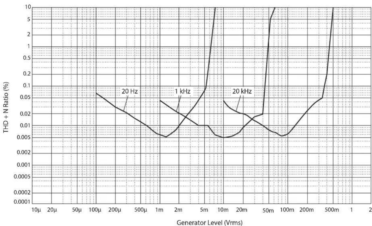
Ko3ΦnucneHT HeiHHeiHbIX nCKaJKeHn (PHONO)
HΦpa3ByKOBoI ΦnIbTp
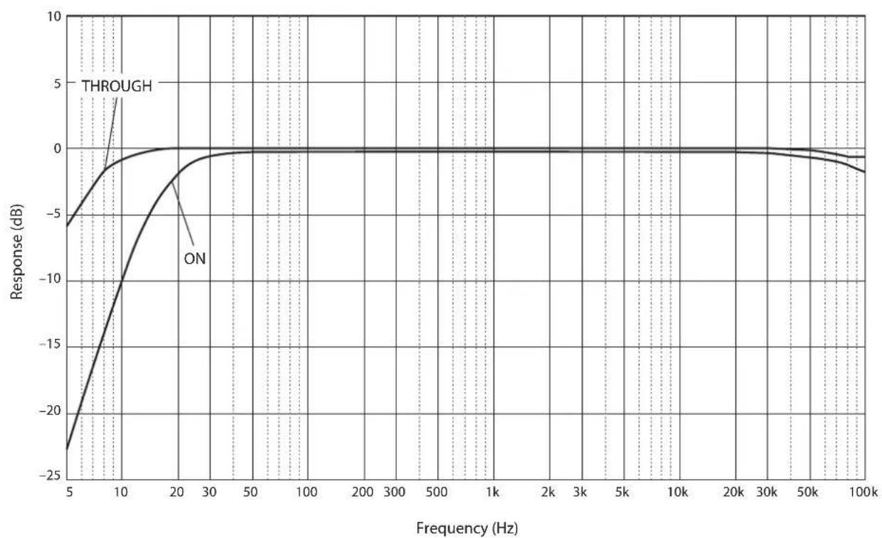
Kpmba rpoMkoCTn
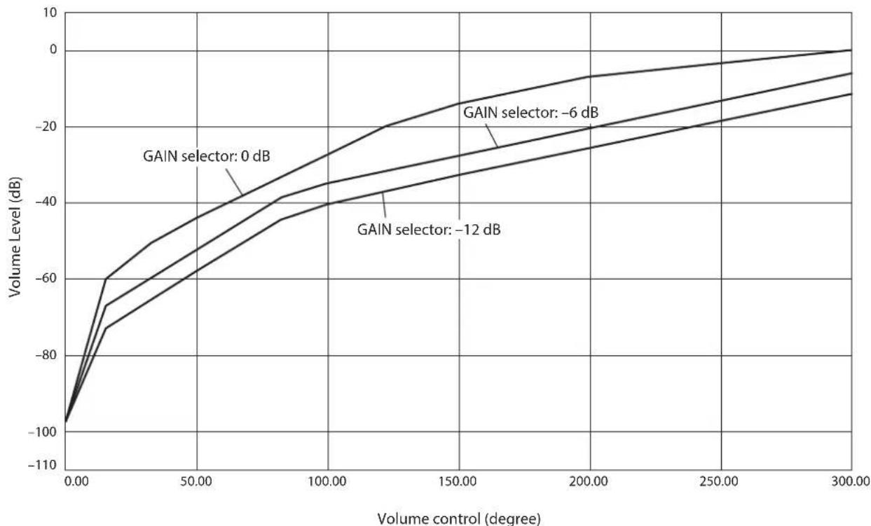
Bo3MOxHbIe HeuCnpaBHOCTN I cnoc6bIXx yCTpaHeHnI
Ecn nn Hn anapat pa6oatae He npabHbHo, cm. Ta6JNUy Hnke. Ecn HncippaBHOCTb He yka3aHa B Ta6JIuie Hn BHe cMOJIn ycTaHHTb ee, cJeIy HnCtpyKIIHM Ta6JIuHb, OTKIOUHTe aIInapat, OTCoeINHITe CnIOBOi Ka6JIb H 6paHTecb K 6JIHKaIIcMcy ABTOpH3OBAHHOMy IIIEpy IN B ccpBnchBn IeHTp YamaHa.
| Heincpapabnoctb Пичina Cnoco6 yctpanenenia Cm.стр. | |||
| Питане не Велиочаетс. | Слобов Кабел Н подочуен К заиму AC IN на заиму панелей яйпьун в розту лесен Horо Ток. | Плковские саловский саловский cootbetCTbyuolum Obla3om. | 306 |
| Данный саллар.Tлбергся сальногу лесатриechкому наразжени OT BVEшник Истонник (налример, молноя яй сальhoe CTatuneckoe лесатриechв). | Быковские саловский саловский cootbetOT розту лесен Horo TOKA, подочу的老 Okono 30сянд, a zatem сюва подочу саллар. | 306 | |
| Имeel сproblema c Bvytrpenhimi sxemamnдан Horo annapata. | Олковские саловский саловский cootbetК подочу的老Та в образлесь к подочу АВTORINIOBAHOMU ДИЕРУ IYI B cepBicnbYцentr YamaHa. | 306 | |
| Звк не снышen. | Кабел Вхда/вхда 6ыліпослочны He nprabinlbNo. | Правл�но подочу的老 Салу Искрпавrostь coхсангетс, кабел могутSBытdeфektbIMn. | 300 |
| Ньл bbl blybrancoobetCTbyuossi nctouhnik. | С пошью салекtopа INPUT на пошney панели (плл однои зз салекtopьх конлор k intочни вхдогу синнala на полte ДY) blyberite cootbetCTbyuolum Истонik BXODHORO синнala. | 308 | |
| Пложенье салекtopа OUTPUT He cootbetCTbyeT nCOnl3yembIM BxODHBM rHe3dAm. | Быserite cootbetCTbyuolum Вьхodс сnomошью салекtopа OUTPUT. | 308 | |
| Невозмен nootregulipovabt у探测ь громкости. | Вариант EXT.DIRECT blybranв в качеве IncotchNiKa BxODHORO синнala. | ОтreyларуITE gromkoctь на подочenvHom komIoонente. Лбо подочу ВHEшни komIoонente K пape BXODNbIX rHe3d, OTlquhnybIX OT rHe3dEXT. IN, a zatem blyberite cootbetCTbyuolum Источник BXODHORO синнala. | 300 308 |
| Звк снышen ИЗ калонки тOLTь одногу канala. | Восрочьв徜аяшиkompoentnet nookluyen He nprabinlbNo. | Убетiletsв в TOM, чTO подочу Ид�пньпсьпь. Былonahevblправильно. ECSII Искрпавrostь coхсангетс, кабел могутSBытdeфektbIMn. | 300 |
| Héncnpabnoctb Ппч. | Инспаьськг. | Ispavilho no podkluchite ka6eili.Есл нсраввсьость coхсан'tя, ka6eili Mогут 6ыт DeфektbIM. | 300 |
| Пошррьвateь He 3a3emlen чered TEmpinhal GND. | Порочite npoirрьвateь к Терminалу GND dathoro appapata. | 302 | |
| Симmetричные и линneyные ka6eili И сponьзOTь ODнOBpeMeHNo MeKdУ DByMa КOMIOHENTAm. | He ispoJIb3yIte cimmetpruHbIe i linneHbIe ka6eili odnoBpeMeHNo Mekdy DByMa KOMIOHENTAm.ЗTo Может сфOPMIPoBaT b KONTyp 3a3emlenia, KOTopbI cos3daet STATUeCKIe NOMEXI n shm. | 300 | |
| Восрочевedingne aydnocgHana c komnoentA, pondknoeHHORO К симmetpruHbIM BXODhIM rHe3dAm BAL 1 по BAL 2, 3byuHt nckaxeHNo. | Урочь сигналь в симmetpruHbIX BxODhIX rHe3dax празыаETДОуCTMlbI BXODHou yproBeH. | Eclу урочь сигналь в симmetpruHbIX BxODhIX rHe3dax TIna XLR Na PodkluchENHOM Восрочь BodaIeM KomnoHente B Два раза 6obIe no copBHeNIO C НecimmetpruHbIMr rHe3dAmRCA, установite сelenkopf ATTENUATOR, pacnoJoxeHbIM NOBxOHNIM rHe3dAm, B noLOXeHne ATT. (-6 nb). | 310 |
| ВниKennч чastotax OTcyTCTByet rIy6uHa, korda Вbl6pano Зачение BAL 1 по BAL 2 (симmetpruHbI BXoD). | Неверhoe зачени полурноcti. | Быберite nprabinbHyIO polarpoctb c помоцьу сelenkoptra PHASE. | 294 |
| Урочь rPOMKOstn Винлобови пlaCTINHKN Слишkom Ni3Kni. | Пerekniochten PHONO Na пerejdne NaHelen uCTahOBlen B нeprabinlbHoe pIoJoxeHne. | ПerebeJte nepeKljuOatelb PHONO B noLoJoxeHne MM nll MC B coOTbETCBM C TINOM MaHHTHO rOLOBKN 3ByKOCHMATEJI пошррьвateЯ. | 309 |
| Пульт Ду не pa6otoet надlexaamm образом. | Пульт Ду Incplb3yETc За рideламп рбочero dmaIa3Ona. | Пульт Ду дOLжен Incplb3ObTaCBA В рideлax Maksimailho PacStOJHn6 M nPod yrglom He 6bONEe 30 rpaDCsOB BheOCEBO rOKIOHEn OT ceHCopa Dny napeJen naHeli. | 298 |
| Празм oleonadache coIlnchbIX Lucey nll ocBeSeHnY (OT INHercepHNO phlyopecuntHNO LamMbI, stpo6oKoNa n T,d) Na ceHcop Dny na peedNei naHeli. | Изmenite oprieNTaIIO nCTOChnka CBeta nll noLOXeHne annapata. | 298 | |
| Раразженьibles 6bTapeiKn. Поменя Ite BCE 6bTapeiKn. 298 | |||
yka3aTeJIb
s
SUBSONIC FILTER 310
B
BkIOueHHe IITaHHa 286
F
Tnc3IOACIN 306
THe3IO BAL 293
Tnc3IO BAL 1 291
Tnc3IO BAL 2 291
THe3IO External In 303
Tnc3IOEXT.IN 303
THe3IO LINE 1 293
THe3IO LINE 2 293
ΓHc3IO LINE 2 IN 292
THe3IO LINE 2 OUT (aIIINc6b) 292
Tnc3IO PHONES 312
ΓHc3IOno Phono 302
THe3IO PHONO 302
ΓHc3IO REMOTE 305
THe3IO SERVICE 293
THe3IO TRIGGER 304
A
IHaTHHIOHHoe coeHHHeHHe 305
M
HHKATop STANDBY/ON/OFF 286
HnKaTopIHTaHne 286
H
HactpoiKa BxoDHoro CnHaJa IponIrpBbateJr... 309
HechMMMeTpHHeoe coeHHHeHne 295
#
IpekeJIOHaTeJIb AUDIO MUTE 311
IpeckJIOHuaTeJIb AUTO POWER STANDBY... 293
IpekeJIIOuateJIbEXT.DIRECT 309
IpcckJIOHauTeJIb STANDBY/ON/OFF 286
IpeKJIOHauTeJIb SUBSONIC FILTER 310
IIpeKJIIOUaTeJIb IIHTaHHe 286
IIOKJIIOUcHHe 3aINHCbIBaHOIIeTO KOMIOHeHTa... 302
IoiKIOHHe HauHHKOB 312
IoiKIOueHHe IPOHpBbAteJIa 302
PioknHcHc ca6Bypepa 303
IIOKIIIOueHHe yCHJIHTeJRA MOIOIOCTH 303
P
Perylntop BALANCE 311
PeryIaTOp BASS 311
PeryJrTop TREBLE 311
Peryltrap VOLUME 310
C
CeJIeKTop ATTENUATOR 310
CeJekTop GAIN 310
Cejektop INPUT 308
CenekTop OUTPUT 308
CeJekTop PHASE 294
CenekTop PHONO 309
CefekTop TRIM 312
Cencop nctaHIOHO ynpabIeHH 298
ChmmertpHnIOe coedHHeHne 294
T
TcpmHaJI SIGNAL GND 302
TepMHHaJI 3a3eMJIeHHJ 302
TcpmHnHaJI 3a3eMJIeHHn eHHaJa 302
TpHrTepHoe coeHHHeHHe 304
Yamaha Global Site
https://www.yamaha.com/
Yamaha Downloads
https://download.yamaha.com/