XDAQS5400RK - Home cinema amp YAMAHA - Free user manual and instructions
Find the device manual for free XDAQS5400RK YAMAHA in PDF.
| Product Type | Multi-zone home theater amplifier |
| Brand | YAMAHA |
| Model | XDAQS5400RK |
| Dimensions (with front cover) | 481 x 44 x 453 mm |
| Dimensions (table mount without rack) | 437 x 46 x 453 mm |
| Weight | Not specified (estimated ~5 kg) |
| Power Supply | AC 120 V (USA) / AC 220-240 V (other), 50/60 Hz |
| Power Consumption | 130 W (max), standby 0.2 W (network off) |
| Output Power (NORMAL, 4 Ω) | 90 W x 2 (two channels), 100 W x 1 (one channel) |
| Output Power (BRIDGE, 8 Ω) | 100 W x 2 (two channels), 200 W x 1 (one channel) |
| Number of Zones | 4 independent zones |
| Network | Ethernet (2 ports), MusicCast, AirPlay, Internet radio |
| Audio Inputs | 2 x stereo RCA (CUT IN, AUX) |
| Audio Outputs | 4 x speakers (Euroblock terminal), 4 x PRE OUT RCA |
| USB | 4 x USB Type-A (FAT16/32, 5 V/0.5 A) |
| Supported Audio Formats | WAV, MP3, WMA, AAC, FLAC, ALAC, AIFF |
| Special Features | MusicCast, Cut/Fade, chime (CHIME), 12V trigger, EQ |
| Maintenance and Cleaning | Wipe with a soft, dry cloth; do not use solvents |
| Safety | Read the provided safety brochure before use |
| Spare Parts and Repairability | Contact an authorized Yamaha dealer for parts and repairs |
| Supplied Accessories | Front cover, anti-slip pads (4), power cord, user manual, safety brochure |
Frequently Asked Questions - XDAQS5400RK YAMAHA
User questions about XDAQS5400RK YAMAHA
0 question about this device. Answer the ones you know or ask your own.
Ask a new question about this device
Download the instructions for your Home cinema amp in PDF format for free! Find your manual XDAQS5400RK - YAMAHA and take your electronic device back in hand. On this page are published all the documents necessary for the use of your device. XDAQS5400RK by YAMAHA.
USER MANUAL XDAQS5400RK YAMAHA
Multi Zone Amplifier
Amplificateur Multizone
XDA-QS5400RK
(XDA-QS5400 + Brackets)
(XDA-QS5400 + Supports)
OWNER'S MANUAL
MODE D'EMPLOI
PART NAMES AND FUNCTIONS 4
Front panel 4
Rear panel 5
PLACEMENT AND CONNECTION 6
Placing the unit 6
Mounting the unit on a rack.... 6
Placing the unit without a rack 6
Connecting devices 7
Connecting speakers 8
Connecting speakers in bridge mode 8
Connecting to a wired network 8
Connecting external devices 8
Connecting the power cord 8
MusicCast 9
What is MusicCast? 9
Installing MusicCast CONTROLLER 9
Adding the unit to the MusicCast network ..... 9
SETTING THE UNIT 10
Setting from a web browser 10
Web Setup screen.... 10
Confirming the IP Address of the unit...... 10
Displaying the Web Setup screen.... 11
Setting menu items 12
FIRMWARE UPDATING 15
Updating the firmware with USB memory devices 15
INITIALIZING THE UNIT 15
Restoring it to the factory preset settings ..... 15
SPECIFICATIONS 16
Specifications 16
Supported devices and file formats .... 18
Supported USB devices 18
Supported AirPlay devices.... 18
Supported file formats.... 18
Block diagram.... 18
TRADEMARKS 19
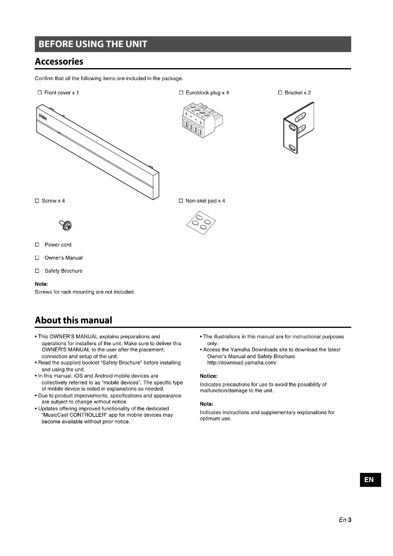
Accessories
Confirm that all the following items are included in the package.
□ Front cover x 1
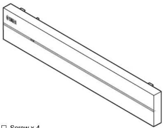
natural_image
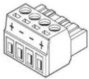
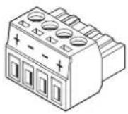
Isometric line drawing of a rectangular electronic component with a diagonal seam and mounting holes (no text or symbols)□ Euroblock plug x 4
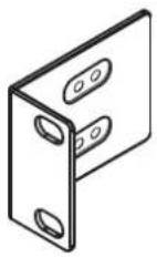
□ Bracket x 2
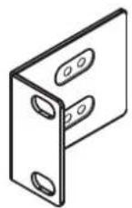
□ Screw x 4

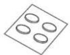
□ Non-skid pad x 4
□ Power cord
□ Owner's Manual
□ Safety Brochure
Note:
Screws for rack mounting are not included.
About this manual
- This OWNER'S MANUAL explains preparations and operations for installers of the unit. Make sure to deliver this OWNER'S MANUAL to the user after the placement, connection and setup of the unit.
- Read the supplied booklet "Safety Brochure" before installing and using the unit.
- In this manual, iOS and Android mobile devices are collectively referred to as "mobile devices". The specific type of mobile device is noted in explanations as needed.
- Due to product improvements, specifications and appearance are subject to change without notice.
-
Updates offering improved functionality of the dedicated "MusicCast CONTROLLER" app for mobile devices may become available without prior notice.
-
The illustrations in this manual are for instructional purposes only.
- Access the Yamaha Downloads site to download the latest Owner's Manual and Safety Brochure. http://download.yamaha.com/
Notice:
Indicates precautions for use to avoid the possibility of malfunction/damage to the unit.
Note:
Indicates instructions and supplementary explanations for optimum use.
PART NAMES AND FUNCTIONS
Front panel
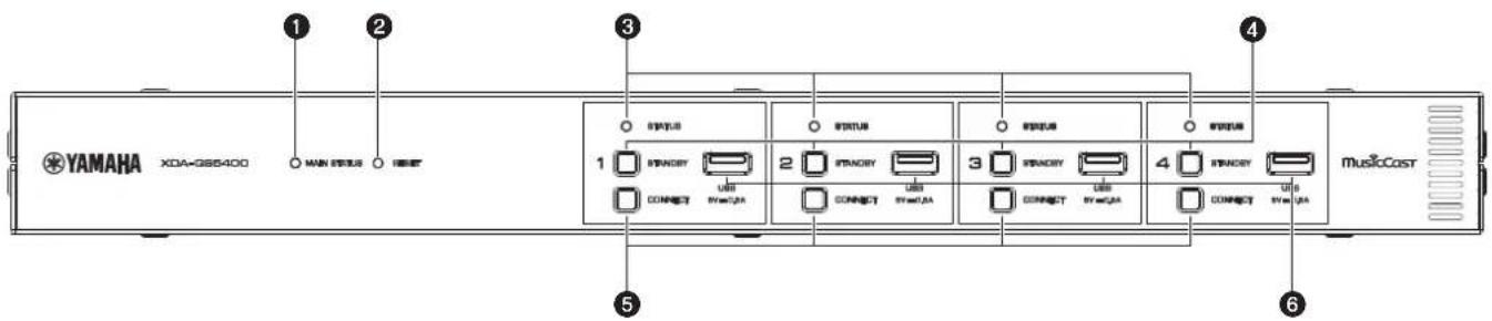
①MAIN STATUS indicator
Indicates the unit status depending on its color and whether it is lit or flashing.
| – Unlit Standby | ||
| White Lit Power on | ||
| Green Flashing Setting up the MusicCast connection | ||
| Dark red Lit Network Standby or ready for Cut / Fade function | ||
| Red | Lit or flashing | Error occurred |
Note
- When flashing green or red, the corresponding ZONE's STATUS indicator also flashes.
- The Cut / Fade function means that the audio signals that are input to CUT IN : IN (SENSING) jacks "cut in" or fade in the playback in each ZONE.
②RESET key
Resets the unit. The unit is restarted forcibly by holding down RESET key for over 10 seconds.
③STATUS indicators
Indicate the ZONE1 - ZONE4 status depending on whether they are lit or flashing.
| - Unlit Standby |
| White Lit Power on |
| Flashing Setting volume or selecting input |
4STANDBY keys
Turn ZONE1 - ZONE4 to on / standby. The unit consumes a small power even in standby mode. The unit's standby power consumption depends on the standby configuration.
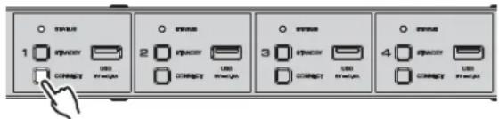
⑤CONNECT keys
Add ZONE1 - ZONE4 to the MusicCast network using the MusicCast CONTROLLER app. The 4 ZONEs are independent of each other, so make sure to connect the mobile device with the MusicCast CONTROLLER app installed to the operating ZONE individually.
6USB jacks
- Connection: USB Type-A
- File format system: FAT16, FAT32
• Voltage / current supply capacity: 5 V / 0.5 A
For connecting a USB storage device. You can play back music files stored on a USB storage device when you select "USB" as the input source.
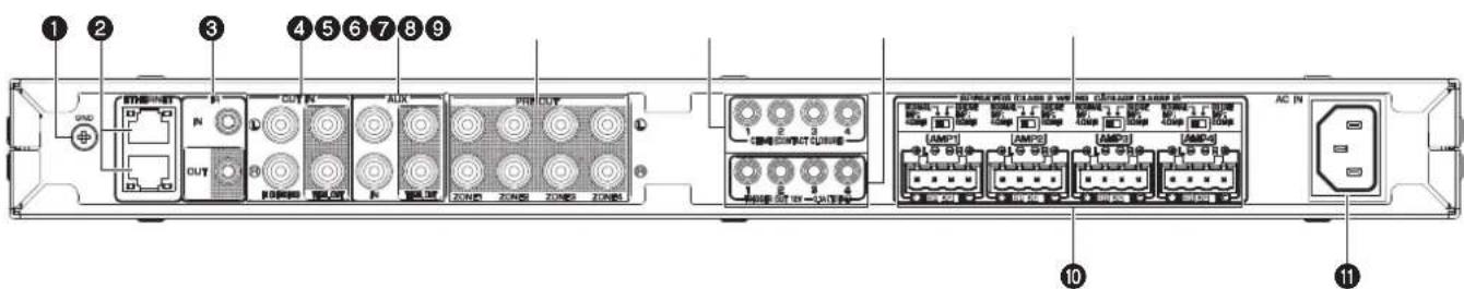
①GND screw terminal
Connecting the source device chassis to the GND terminal of the unit may reduce noise in the signal.
Note
The ground is not a safety ground.
②ETHERNET jacks
Connection: RJ-45
For a wired connection to a network. Using an ETHERNET jack, connect the unit to your router with an Ethernet cable. Using another ETHERNET jack, you can connect the unit to another network device (such as another XDA-QS5400) in cascade.
Notice
The unit is equipped with an Ethernet hub (Layer-2 Ethernet switch) internally. Do not connect both ETHERNET jacks to the same router. In that case, a routing loop might interfere with communication of the whole network.
③IR IN/OUT jack
Connection: 3.5 mm monaural mini-plug
For connecting to an external remote control device and inputting/outputting remote control signals. The output with pass-through function is enabled even in standby mode.
④ CUT IN : IN (SENSING)/THRU. OUT jacks
Connection: stereo RCA plug (L/R)
IN (SENSING): For connecting to a paging system or another audio device. The audio signals cut in or fade in the playback in each ZONE.
THRU. OUT: For outputting analog audio signals input in IN (SENSING) jacks by pass-through function. The output is enabled even in standby mode.
⑤ AUX : IN/THRU. OUT jacks
Connection: stereo RCA plug (L/R)
IN: For connecting to an audio playback device such as a CD player (analog out jack) and inputting audio signals.
You can play back music from an audio playback device when you select "AUX" as the input source.
THRU. OUT: For outputting analog audio signals input in AUX : IN jacks by pass-through function. The output is enabled even in standby mode.
⑥PRE OUT/ZONE1- 4 jacks
Connection: stereo RCA plug (L/R)
For connecting to external power amplifiers and outputting audio signals in ZONE1 - ZONE4.
⑦CHIME (CONTACT CLOSURE) 1–4 jacks
Connection: 3.5 mm monaural mini-plug (Tip: + / Sleeve: -) For connecting to contact closures such as door bells. When the contact closure is closed (+ and - of the jack is shorted), the preset chime sounds in the selected ZONE.
⑧TRIGGER OUT 1-4 jacks
Connection: 3.5 mm monaural mini-plug (Tip: + / Sleeve: -) For outputting trigger signals (DC 12 V). In general, the output level is "High" when the unit is powered on or "Low" in standby mode.
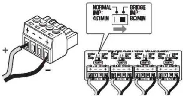
⑨NORMAL/BRIDGE switch
Selects NORMAL/BRIDGE connection of speakers. This switch is normally set to NORMAL. Change the setting to BRIDGE only when the speaker is used in bridge connection.
Note
Unplug the unit's power cord from the AC wall outlet before changing the NORMAL/BRIDGE switch setting.
⑩ SPEAKERS terminals
Connection: Euroblock connectors (supplied)
Speaker impedance: 4 Ω or over (NORMAL), 8 Ω or over (BRIDGE)
For connecting to speakers with supplied Euroblock connectors.
⑪ AC IN jack
For connecting the supplied power cord.
Placing the unit
■ Mounting the unit on a rack
Use the supplied brackets to mount the unit on an EIA standard rack. Screw the brackets to the unit horizontally.

Notice
- Do not use the brackets for devices other than the XDA-QS5400.
- When installing brackets, use the included screws.
- Tighten the screws until the brackets are securely fixed.
Note
Screws for rack mounting are not included.
Precautions for rack mounting
If the unit is mounted together with additional units and/or other devices in an EIA standard equipment rack, the internal temperature can rise due to heat generated from the devices, resulting in impaired performance. If the unit is mounted in a rack, always observe the following requirements to avoid heat buildup:
- If the unit is mounted in a rack with other devices that generate a significant amount of heat, such as a power amplifier, leave more than 1U of space between the unit and other devices (both above and below). Also, make sure to either leave any open spaces uncovered or install appropriate ventilating panels to minimize the possibility of heat buildup.
- To ensure sufficient airflow, leave the rear of the rack open and position it at least 10 cm from walls or other surfaces.
■ Placing the unit without a rack
Affix the supplied non-skid pads at the four corners on the bottom of the unit, and then place the unit on a shelf or rack.
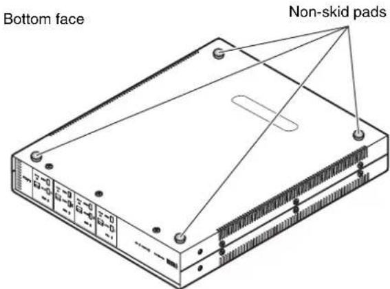
Note
Allow ventilation space of at least 10 cm (4 in.) on the top, either side and back of the unit.
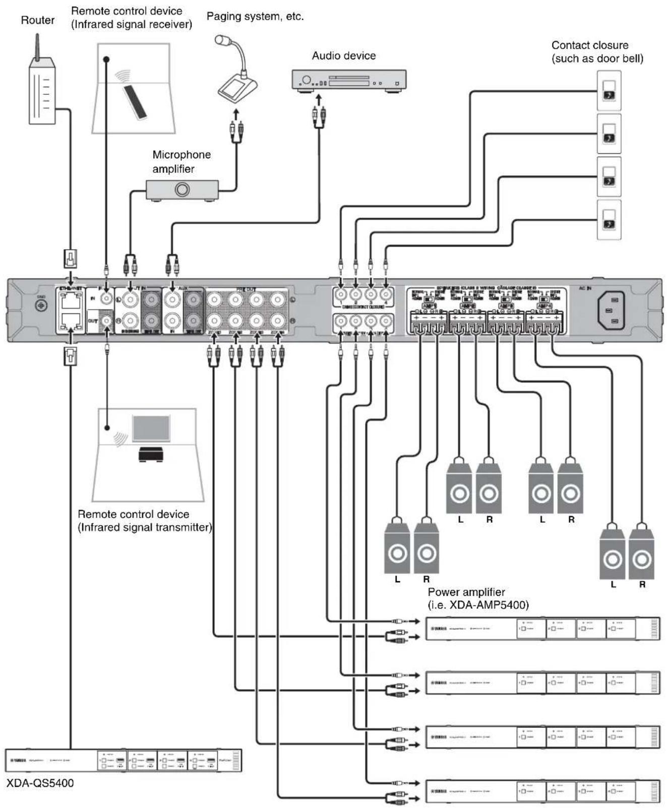
The following is an example of connecting the devices. Unplug the unit's power cord from the AC wall outlet before connecting the devices.
flowchart
graph TD
    A["Router"] --> B["Remote control device (Infrared signal receiver)"]
    B --> C["Microphone amplifier"]
    C --> D["Audio device"]
    D --> E["Contact closure (such as door bell)"]
    E --> F["Power amplifier (i.e. XDA-AMP5400)"]
    F --> G["XDA-QS5400"]
    G --> H["Remote control device (Infrared signal transmitter)"]
    H --> I["Microphone amplifier"]
    I --> J["Audio device"]
    J --> K["Contact closure (such as door bell)"]
    K --> L["Power amplifier (i.e. XDA-AMP5400)"]
    L --> M["XDA-QS5400"]
    style A fill:#f9f,stroke:#333
    style B fill:#ccf,stroke:#333
    style C fill:#cfc,stroke:#333
    style D fill:#fcc,stroke:#333
    style E fill:#cff,stroke:#333
    style F fill:#ffc,stroke:#333
    style G fill:#cfc,stroke:#333
    style H fill:#fcc,stroke:#333
    style I fill:#cfc,stroke:#333
    style J fill:#fcc,stroke:#333
    style K fill:#cfc,stroke:#333
    style L fill:#fcc,stroke:#333
    style M fill:#cfc,stroke:#333
EN
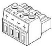
■ Connecting speakers
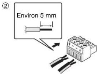
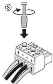
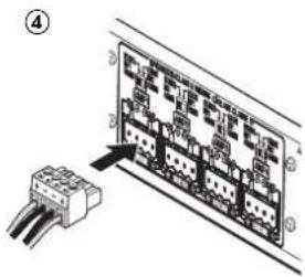
Connect the speakers to the unit with the supplied Euroblock plug and commercially-available speaker cables.
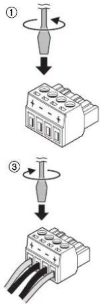
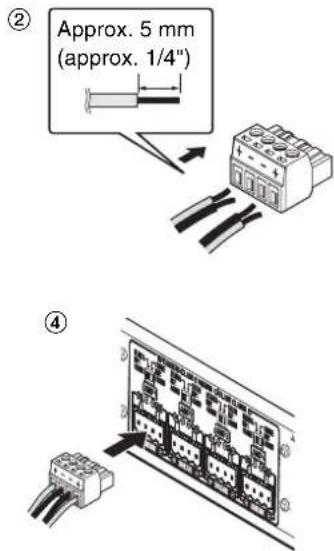
1 Loosen terminal screws.
2 Insert cables.
3 Securely tighten terminal screws.
4 Insert the Euroblock plug into the SPEAKERS terminals of the unit.
Note
- You must use the supplied Euroblock plugs. If the plugs have been lost, please contact your Yamaha dealer.
- Recommended cable gauges for the Euroblock plug: AWG26 (0.13 mm ^2 ) to AWG16 (1.3 mm ^2 )
- To prepare the cable for attachment to a Euroblock connector, strip the wire as shown in the illustration using stranded wire to make connections. With a Euroblock connection, stranded wires may be prone to breakage because of metal fatigue due to the weight of the cable or due to vibration. When rack mounting your device, use a lacing bar when possible to bundle and fasten the cables.
- Do not tin (solder) the exposed end.
■ Connecting speakers in bridge mode
Connect the speakers to the unit with the supplied Euroblock plug and commercially-available speaker cables, and set the NORMAL/BRIDGE switch to "BRIDGE".
Note
Unplug the unit's power cord from the AC wall outlet before changing the NORMAL/BRIDGE switch setting.
■ Connecting to a wired network
Connect the unit to your router with a commercially-available STP network cable (CAT-5 or higher straight cable).
Using another ETHERNET jack, you can connect the unit to another network device (such as another XDA-QS5400) in cascade.
Notice
Do not connect both ETHERNET jacks to the same router. In that case, a routing loop might interfere with communication of the whole network.
■ Connecting external devices
■ For a power amplifier
Use a commercially-available analog stereo pin cable (stereo audio RCA cable). You can connect a power amplifier to each ZONE.
Note
To prevent loud sound or unexpected noise, before connecting a power amplifier, be sure to unplug the unit's power cord from the AC wall outlet and turn off the power amplifier.
■ For an external device with analog stereo audio output Use a commercially-available analog stereo pin cable (stereo audio RCA cable).
■ For a paging system with the Cut/Fade function
Use a commercially-available analog stereo pin cable (stereo audio RCA cable). The audio signals from a paging system cut in or fade in the playback in each ZONE.
Note
Control the Cut/Fade function using the Web Control screen. For details, see the following:
- "Setting menu items" (p.12)
■ For a contact closure (such as a door bell) with the ON/OFF switch
Use a commercially-available 3.5 mm monaural mini-plug cable. When the contact closure is closed, the preset chime sounds in the selected ZONE.
Note
Control the chime function using the Web Control screen. For details, see the following:
- "Setting menu items" (p.12)
■ For a remote control device
Use a commercially-available 3.5 mm monaural mini-plug cable. For connecting to an infrared signal receiver/emitter that allows you to operate the unit and other devices from another room.
■ For a device compatible with the trigger function
Use a commercially-available 3.5 mm monaural mini-plug cable. The trigger function can control external devices (such as XDA-AMP5400) in conjunction with powering on/off the unit.
Note
Control the trigger function using the Web Control screen. For details, see the following:
- "Setting menu items" (p.12)
■ Connecting the power cord
After all the connections are complete, plug the supplied power cord into the AC IN jack on the rear panel, and then plug the power cord to an AC wall outlet.
What is MusicCast?
MusicCast allows you to share music among all of your rooms with a variety of Yamaha MusicCast compatible devices. Yamaha offers the free dedicated mobile app "MusicCast CONTROLLER". This app allows the users of this unit to control the unit and other MusicCast compatible devices easily. Users can also enjoy music from their mobile device, media servers (PCs/NAS), and music streaming services. For more details and a lineup of MusicCast compatible products, refer to the following site: http://www.yamaha.com/musiccast/
Note
Some streaming services may be asked to login from MusicCast CONTROLLER app.
Installing MusicCast CONTROLLER

To use the network features on the MusicCast compatible device, you need the dedicated application "MusicCast CONTROLLER". Search for the free application "MusicCast CONTROLLER" on the App Store or Google Play and install it to your device.
Adding the unit to the MusicCast network
Perform the following procedure to add each ZONE to the MusicCast network.
1 Tap the "MusicCast CONTROLLER" application icon on your mobile device and tap "Setup".
Note
If you want to add the unit to the MusicCast network in the next ZONE, tap "Add New Device" in the "Settings".
2 Operate the "MusicCast CONTROLLER" application following the on-screen instructions, and then hold down CONNECT on the front panel of the unit for 5 seconds.
3 Operate the "MusicCast CONTROLLER" application following the onscreen instructions to set up the network.
This completes adding the unit to the MusicCast network.
Setting from a web browser
■ Web Setup screen
You can modify the various unit settings with the Web Setup screen displayed in a web browser on your mobile device (such as a tablet) or PC.
XDA-QS5400 - Web Setup

The Web Setup screen appears when you type the IP address of the unit followed by "/Setup" into the address field of a web browser. You can configure the various settings in ZONE1 to ZONE4 all together.
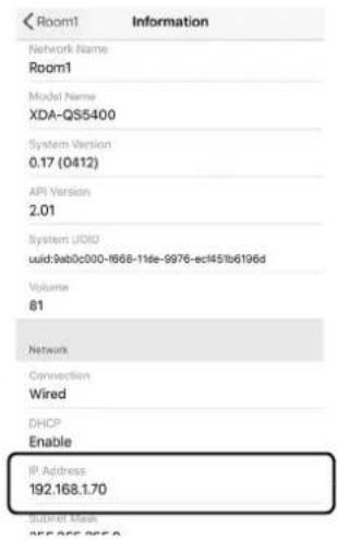
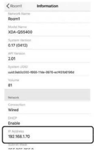
■ Confirming the IP Address of the unit
Follow the procedure below to confirm the IP Address of the unit after setting up MusicCast.
1 Hold down the room name (or the unit name) on the MusicCast CONTROLLER screen.
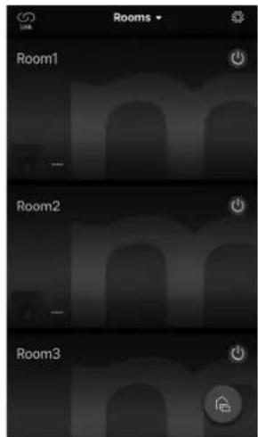
2 Tap "Room Settings".
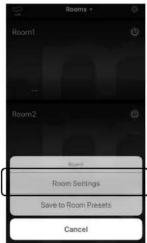
3 Tap "Information", and check the IP Address of the unit.
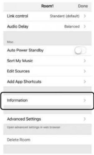
■ Displaying the Web Setup screen
Using the IP Address of the unit, you can display the Web Setup screen.
Type the IP Address of the unit followed by "/Setup" into the address field of a web browser on your mobile device (such as a tablet) or PC, and press ENTER. The Web Setup screen for the unit appears.
For example:
http://192.168.1.70/Setup
Note
Be sure not to type only the IP address of the unit into the address field of a web browser. The Web Setup screen does not appear without "/Setup".
XDA-QS5400 - Web Setup
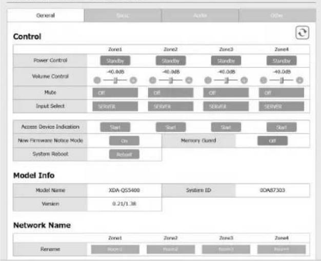
The following items can be displayed and configured on the Web Setup Screen.
Tab Menu Item Setting values Default Explanation
| General Control Power Control Standby / On Standby Turns on/off (standby) each Zone. “Off” could include Network Standby | ||||
| Volume Control | Mute / -80.0 to 0.0dB(0.5dB Steps) | -40.0dB Adjusts the volume in each Zone. | ||
| Mute Off / Att | -20 dB / Att -40 dB /On | Off Mutes the audio output in each Zone. | ||
| Input Select | (streaming services) / AirPlay / MusicCast Link / SERVER / NET RADIO / USB / AUX | SERVER | Sets an input source in each Zone. | |
| Access Device Indication | - | - | Flashes the STATUS indicator of the device (ZONE) currently being used for operation via a web browser. | |
| New Firmware Notice Mode | Off / On | On Enables/disables a mode that gives notification of new firmware on the MusicCast CONTROLLER screen. | ||
| Memory Guard | Off / On | Off | Protects the settings of the unit and prevents them from being modified. | |
| System Reboot | - | - | Restarts the entire system. | |
| Model Info | Model Name | - | - | Displays the model name of the unit. |
| System ID - | - | - | Displays the system ID of the unit. | |
| Version | - | - | Displays the version of firmware currently installed on the unit. | |
| Network Name | Rename - | - | - | Edits the network name (the Zone's name on the network) displayed on other network devices. |
| Network Info | IP Address | - | - | Displays the IP address for each Zone. |
| Subnet Mask | - | - | Displays the subnet mask for each Zone. | |
| Default Gateway | - | - | Displays the IP address of the default gateway for each Zone. | |
| DNS Server (P) | - | - | Displays the IP address of the primary DNS server. | |
| DNS Server (S) | - | - | Displays the IP address of the secondary DNS server. | |
| MAC Address | - | - | Displays the MAC address for each Zone. | |
| Network Settings | DHCP | Off / On | On Enables/disables the DHCP function. | |
| IP Address | - | - | Sets the IP address for each Zone. | |
| Subnet Mask | - | - | Sets the subnet mask for each Zone. | |
| Default Gateway | - | - | Sets the IP address of the default gateway for each Zone. | |
| DNS Server (P) | - | - | Sets the IP address of the primary DNS server. | |
| DNS Server (S) | - | - | Sets the IP address of the secondary DNS server. | |
| Tab | Menu | Item | Setting values | Default | Explanation |
| Basic Settings Output Select | Zone1 / Zone2 / Zone3 / Zone4 / None | AMP1 - Zone1, AMP2 - Zone2, AMP3 - Zone3, AMP4 - Zone4 | Sets the zone as the audio output in each channel. | ||
| Trigger Out Power sync / Manual | Power sync Specifies the condition for the TRIGGER OUT jack to function."Power sync": functions in sync with the power status (On/Off)."Manual": manually switches the output level (High/Low) for electronic signal transmission. | ||||
| Manual Control Hi / Lo Hi Sets the output level (High/Low) for the TRIGGER OUT jack. | |||||
| AirPlay Volume Interlock | Off / Limited / Full Limited Sets whether or not the volume of the Zone and the volume of iTunes or the iPhone are synchronized when AirPlay input is selected. | ||||
| Audio Settings Equalizer | Mode Bypass / Auto / Manual | Auto Adjusts the volumes for the low-frequency, middle-frequency, and high-frequency ranges of the audio. When this is "Auto", they stay synchronized with the volume and perform hearing correction for the auditory response of the human ear. | |||
| Equalizer Manual : High | -6.0 to +6.0dB (0.5dB Steps) | 0.0dB Adjusts the volume of the high-frequency range of the audio output. | |||
| Equalizer Manual : Mid | -6.0 to +6.0dB (0.5dB Steps) | 0.0dB Adjusts the volume of the middle-frequency range of the audio output. | |||
| Equalizer Manual : Low | -6.0 to +6.0dB (0.5dB Steps) | 0.0dB Adjusts the volume of the low-frequency range of the audio output. | |||
| Enhancer | Off / On | On | Enables/disables the Compressed Music Enhancer feature. | ||
| Bass Extension | Off / On | Off | Enables/disables enhanced bass sound, regardless of the size of the speakers. | ||
| Monaural Downmix | Off / On | Off | Enables/disables a mode that plays back stereo signals downmixed to monaural audio. | ||
| Speaker Type | Compact / Bookshelf / Floor standing / In-ceiling / In-wall | Bookshelf | Adjusts the effects of features such as Bass Extension for optimal results depending on the speaker type. "Compact": optimizes for small speakers. "Bookshelf": optimizes for bookshelf speakers. "Floor standing": optimizes for large speakers that are placed on the floor. "In-ceiling": optimizes for speakers embedded in the ceiling. "In-wall": optimizes for speakers embedded in walls. | ||
| Initial Volume Mode | Off / On | Off | Enables/disables setting of the initial volume when each Zone is turned on. | ||
| Initial Volume | Mute / -80.0 to 0.0dB (0.5dB Steps) | -40.0dB | Sets the initial volume for when each Zone is turned on. | ||
| Max Volume | -60.0 to 0.0dB (0.5dB Steps) | 0.0dB Sets an upper limit for the volume levels to which each Zone can be adjusted. | |||
| Auto Play | Off / On / Auto | different for every input source | Sets whether or not audio is automatically played back from servers, USB devices, etc. when each Zone is turned on or the input source is switched. "Off": always starts up with playback stopped. "On": starts automatically to play back the last content which you played back. "Auto": starts automatically to play back the last content only if it was being played back when the Zone was set to standby mode. Note The setting value is different for every input source or service. | ||
| Others | Factory Preset | Factory Preset | - | - | Initializes to factory preset settings. |
| Web Settings Link | AirPlay Password | - | - | Sets the Zone's password for AirPlay. | |
| Backup / Restore | - | - | Saves the Zone's current settings to a PC or restores them from a backup on a PC. | ||
FIRMWARE UPDATING
Updating the firmware with USB memory devices
You can update the firmware using USB memory devices. Download the firmware update file from the Yamaha website to a PC, and copy it to 4 USB memory devices in advance.
Note
• Each ZONE needs the firmware update.
- Use 4 USB memory devices to update the firmware of the 4 Zones at once.
1 Turn each ZONE to standby and disconnect the power cord from the AC wall outlet.
2 Connect the USB memory devices to the USB jacks of ZONE1 to ZONE4 on the front panel.
3 While holding down CONNECT1 and CONNECT3 on the front panel, plug the power cord into the AC wall outlet.
The firmware update starts. The STATUS indicator of each ZONE flashes during the update and the MAIN STATUS indicator lights up in sky blue.
4 When the update is finished, press STANDBY1 to reset all of the ZONEs.
When updating is finished, the STATUS indicator on each ZONE is turned off and the MAIN STATUS indicator lights up in white.
INITIALIZING THE UNIT
Restoring it to the factory preset settings
To initialize the unit, select "Factory Preset" from the "Web setup" screen, or set all Zones to standby and then hold down the CONNECT1 and CONNECT2 keys simultaneously for 5 seconds or longer. When it becomes initialized, the power of ZONE1 will also turn on.
Specifications
The specifications of the unit are as follows.
Input jacks
Analog Audio
- Stereo Audio (RCA) x 2 (CUT IN, AUX)
Output jacks
Analog Audio
- Speaker Out x 4 (L/R)
- Stereo Audio (RCA) x 4 (PRE OUT)
- Stereo Audio (RCA) x 2 (CUT IN, AUX)
Other jacks
- USB x 4 (USB2.0)
- Network (Wired) x 2 (Internal speed: 100Base-TX/10Base-T, External speed: 1000Base-T/100Base-TX/10Base-T)
- Trigger Out x 4
- Remote In x 1
- Remote Out x 1
• Chimex 4
USB
Device Capability: Mass Storage Class USB Memory
Current Supply Capacity: 0.5 A
Network
PC Client Function
AirPlay supported
Internet Radio
Streaming Service
Audio Section
Rated Output Power
• (2-channel driven, 1 kHz, 0.9% THD, NORMAL, 4/8 Ω) 90/50 W
• (2-channel driven, 1 kHz, 0.9% THD, BRIDGE, 8 Ω) 100 W
• (1-channel driven, 1 kHz, 0.9% THD, NORMAL, 4/8 Ω) 100/50 W
• (1-channel driven, 1 kHz, 0.9% THD, BRIDGE, 8 Ω) 200 W
Dynamic Power
• (2-channel driven, 20 Hz to 20 kHz, 0.08% THD, 20ms Burst, NORMAL, 4/8 Ω) 80/40 W
• (2-channel driven, 20 Hz to 20 kHz, 0.08% THD, 20ms Burst, BRIDGE, 8 Ω) 150 W
• (2-channel driven, 1 kHz, 0.9% THD, 20ms Burst, NORMAL, 4/8 Ω) 100/50 W
• (2-channel driven, 1 kHz, 0.9% THD, 20ms Burst, BRIDGE, 8 Ω) 200 W
- (All channel driven, 1 kHz, 0.9% THD, 20ms Burst, NORMAL(8-ch), 4/8 Ω) 80/50 W
- (All channel driven, 1 kHz, 0.9% THD, 20ms Burst, BRIDGE(4-ch), 8 Ω) 170 W
Maximum Effective Output Power (JEITA)
• (1-channel driven, 1 kHz, 10% THD, NORMAL, 4/8 Ω) 130/65 W
• (1-channel driven, 1 kHz, 10% THD, BRIDGE, 8 Ω) 260 W
Total Harmonic Distortion (THD)
• (20 Hz to 20 kHz, SP OUT, 25 W, 8 Ω) 0.04% THD
• (20 Hz to 20 kHz, PRE OUT, 1 V) 0.005% THD
Frequency Response (+0/-3 dB)
- PRE OUT (NET/USB IN) 10 Hz to 22 kHz
• PRE OUT (AUX IN) 10 Hz to 22 kHz
• SP OUT (NET/USB IN) 10 Hz to 22 kHz
• SP OUT (AUX IN) 10 Hz to 22 kHz
Signal to Noise Ratio (IHF-A)
- PRE OUT (NET/USB IN) 114 dB
- PRE OUT (AUX IN) 108 dB
- SP OUT (NET/USB IN) 106 dB
- SP OUT (AUX IN) 104 dB
Rated Output Level / Output Impedance
- PRE OUT (L/R, 1 kHz) 2.0 V/470 Ω
Maximum Output Level
- PRE OUT (L/R, 0.9% THD) 4.0 V
Gain
- SP OUT (1 V INPUT) 25.8 dB
Input Sensitivity
• 1 W power (1 W/8 Ω output) 150 mV
• MAX power (50 W/8 Ω output) 1.0 V
Volume Control
• P R E O U T / S P80GB to 0.0 dB (M5 dB Step),
EQ Characteristics
- Bass Variable width -6.0 dB to +6.0 dB (0.5 dB Step)
• Bass Turnover Frequency 350 Hz
- Mid Variable width -6.0 dB to +6.0 dB (0.5 dB Step)
• Mid Center Frequency 1.1 kHz
- Treble Variable width -6.0 dB to +6.0 dB (0.5 dB Step)
- Treble Turnover Frequency 3.5 kHz
Maximum Input Signal
• AUX IN (1 kHz, 0.9% THD) 2.4 V
General
Power Supply
• [U.S.A. model] AC 120 V, 60 Hz
• [Other models] AC 220 to 240 V, 50/60 Hz
Power Consumption 130 W
- All Zone On, No Signal Condition 40 W
- All Zone Off, Chime On 18.2 W
- All Zone Off, CUT IN On, CUT IN Power On Enable 18.2 W
Standby Power Consumption
• Network Standby Off 0.2 W
• Network Standby On (1 Zone) 3.2 W
• Network Standby On (4 Zones) 6.0 W
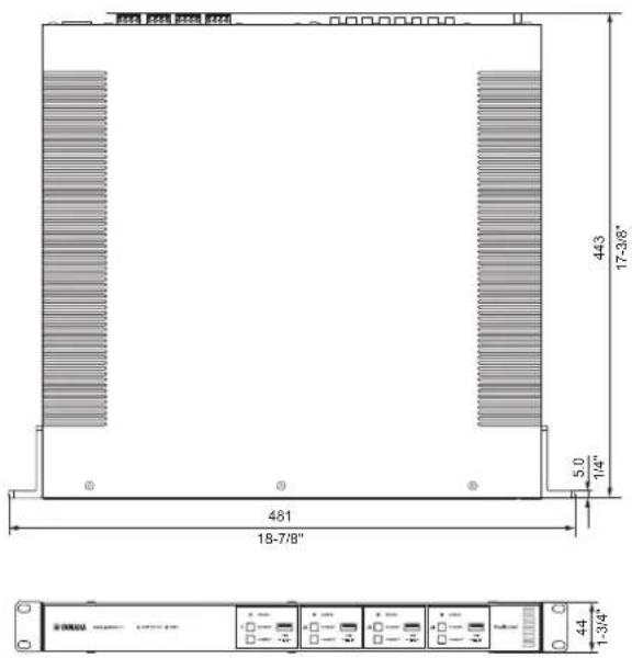
Dimensions (W x H x D)
437 x 46 x 443 mm (17-1/4" x 1-3/4" x 17-3/8")
Weight 6.3 kg (13.9 lbs)
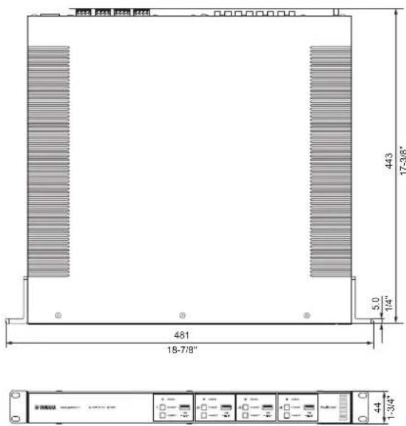
Reference Dimensions
- Brackets with front cover
481 x 44 x 453 mm (18-7/8" x 1-3/4" x 17-7/8")
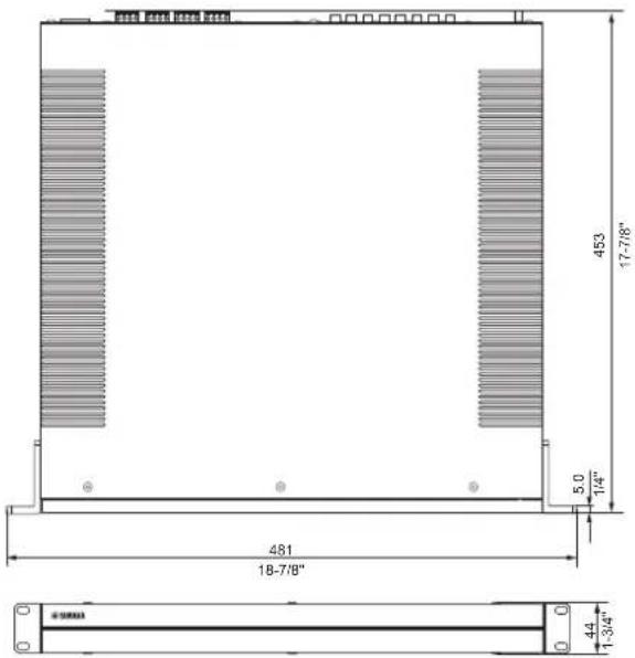
• Table Top Mount-with front cover
437 x 46 x 453 mm (17-1/4" x 1-3/4" x 17-7/8")
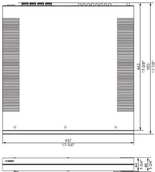
- Brackets
481 x 44 x 443 mm (18-7/8" x 1-3/4" x 17-3/8")
* The contents of this manual apply to the latest specifications as of the publishing date. To obtain the latest manual, access the Yamaha website then download the manual file.
■ Supported USB devices
The following USB devices can be used by the unit.
- The unit is compatible with USB memory devices that are in FAT16 or FAT32 format. Do not connect any other type of USB devices.
- USB devices with encryption cannot be used.
- Operation of all USB devices cannot be guaranteed.
■ Supported AirPlay devices
Made for (as of September 2018):
iPhone X, iPhone 8 Plus, iPhone 8, iPhone 7 Plus, iPhone 7, iPhone SE, iPhone 6s Plus, iPhone 6s, iPhone 6 Plus, iPhone 6, iPhone 5s, iPhone 5c, iPhone 5, iPhone 4s
iPad Pro (10.5"), iPad Pro (12.9") 2nd Generation, iPad Pro (12.9") 1st Generation, iPad Pro (9.7"), iPad mini 4, iPad Air 2, iPad mini 3, iPad Air, iPad mini 2, iPad mini, iPad (6th generation), iPad (5th generation), iPad (4th generation), iPad (3rd generation), iPad 2
iPod touch (6th generation), iPod touch (5th generation)
■ Supported file formats
The following file formats can be used by the unit.
| File Sampling frequency (kHz) | Quantization bits (bit) | Bitrate (kbps) | Number of channels | Support for gapless playback | |
| WAV * 32/44.1/48 | 88.2/96/176.4/192 16/24/32 - 2 √ | ||||
| MP3 32/44.1/48 - 8 to 320 | 2 | - | |||
| WMA | 32/44.1/48 | - | 8 to 320 | 2 | - |
| MPEG-4 AAC | 32/44.1/48 | - | 8 to 320 | 2 | - |
| FLAC | 32/44.1/48/88.2/96/176.4/192 | 16/24 | - | 2 | √ |
| ALAC | 32/44.1/48/88.2/96 | 16/24 | - | 2 | √ |
| AIFF | 32/44.1/48/88.2/96/176.4/192 | 16/24/32 | - | 2 | √ |
* Linear PCM format only. 32 bit-float files cannot be played back.
- The playable file formats differ depending on the software installed on media servers (PCs/NAS). Refer to the instruction manual of the server software for details.
- Digital Rights Management (DRM) content cannot be played back.
■ Block diagram
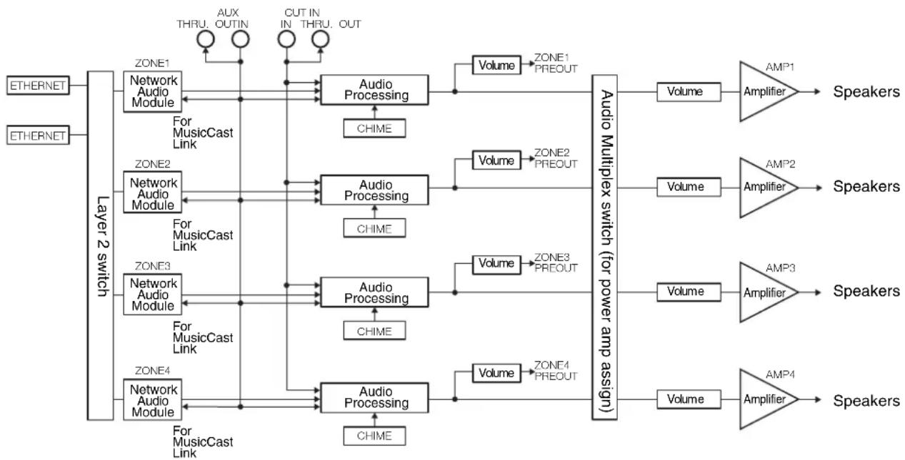
flowchart
graph TD
    A["ETHERNET"] --> B["Layer 2 switch"]
    C["ETHERNET"] --> B
    B --> D1["ZONE1"]
    B --> D2["ZONE2"]
    B --> D3["ZONE3"]
    B --> D4["ZONE4"]
    D1 --> E1["Network Audio Module"]
    D1 --> E2["Network Audio Module"]
    D2 --> E3["Network Audio Module"]
    D2 --> E4["Network Audio Module"]
    D3 --> E5["Network Audio Module"]
    D3 --> E6["Network Audio Module"]
    D4 --> E7["Network Audio Module"]
    E1 --> F1["For MusicCast Link"]
    E2 --> F2["For MusicCast Link"]
    E3 --> F3["For MusicCast Link"]
    E4 --> F4["For MusicCast Link"]
    E5 --> F5["For MusicCast Link"]
    E6 --> F6["For MusicCast Link"]
    F1 --> G1["Audio Processing"]
    F2 --> G2["Audio Processing"]
    F3 --> G3["Audio Processing"]
    F4 --> G4["Audio Processing"]
    G1 --> H1["CHIME"]
    G2 --> H2["CHIME"]
    G3 --> H3["CHIME"]
    G4 --> H4["CHIME"]
    H1 --> I1["Volume"] --> J1["AMP1 Amplifier"] --> K1["Speakers"]
    H2 --> I2["Volume"] --> J2["AMP2 Amplifier"] --> K2["Speakers"]
    H3 --> I3["Volume"] --> J3["AMP3 Amplifier"] --> K3["Speakers"]
    H4 --> I4["Volume"] --> J4["AMP4 Amplifier"] --> K4["Speakers"]
    H1 --> L1["Zone1 PREOUT"] --> M1["Volume"] --> N1["AMP1 Amplifier"] --> O1["Speakers"]
    H2 --> L2["Zone2 PREOUT"] --> M2["Volume"] --> N2["AMP2 Amplifier"] --> O2["Speakers"]
    H3 --> L3["Zone3 PREOUT"] --> M3["Volume"] --> N3["AMP3 Amplifier"] --> O3["Speakers"]
    H4 --> L4["Zone4 PREOUT"] --> M4["Volume"] --> N4["AMP4 Amplifier"] --> O4["Speakers"]

Works with Apple AirPlay
Use of the Works with Apple badge means that an accessory has been designed to work specifically with the technology identified in the badge and has been certified by the developer to meet Apple performance standards.
Apple, iPad, iPad Air, iPad Pro, and iPhone are trademarks of Apple Inc., registered in the U.S. and other countries. App Store is a service mark of Apple Inc.
Android ^TM
Google Play ^TM
Android and Google Play are trademarks of Google LLC.
MusicCast
MusicCast is a trademark or registered trademark of Yamaha Corporation.
Explanations regarding GPL
This product utilizes GPL/LGPL open-source software in some sections. You have the right to obtain, duplicate, modify, and redistribute this open-source code only. For information on GPL/LGPL open source software, how to obtain it, and the GPL/LGPL license, refer to the Yamaha Corporation website. http://download.yamaha.com/sourcecodes/musiccast/
Licenses
For information on the licenses of the third-party software in this product, refer to the following. http://(IP address of this product*)/licenses.html
* IP address of this product can be found with MusicCast CONTROLLER.
TABLE DES MATIÈRES
AVANT D'UTILISER L'UNITÉ 21
Accessoires 21
natural_image
Isometric line drawing of a rectangular object with a diagonal line and two side connectors (no text or symbols)□ Bornier Euroblock x 4 □ Support x 2
□ Vis x 4

①Témoin MAIN STATUS
①Borne à vis GND
natural_image
Isometric line drawing of a rectangular electronic device with ports and connectors (no text or symbols)Remarque
- (une voie, 1 kHz, 10% DHT, BRIDGE, 8 Ω) 260 W
Distorsion harmonique totale (DHT)
- PRE OUT (NET/USB IN) 114 dB
- PRE OUT (AUX IN) 108 dB
- SP OUT (NET/USB IN) 106 dB
- SP OUT (AUX IN) 104 dB
Dimensions (L x H x P)
437 x 46 x 443 mm
Poids 6,3 kg
• Supports
481 × 44 × 443 mm
Works with Apple AirPlay
natural_image
Isometric line drawing of a rectangular object with a diagonal line and two side tabs, labeled 'Ternille x 4' at the bottom (no other text or symbols)□ Tornillo × 4
□ Conector Euroblock × 4
□ Almohadilla antideslizante × 4
□ Soporte × 2
① Terminal de tornillos GND
⑤Tomas AUX: IN/THRU. OUT
⑨Interruptor NORMAL/BRIDGE
| Room1 | Done | |
| Link control | Standard (default) | |
| Audio Delay | Balanced | |
| Misc. | ||
| Auto Power Standby | ||
| Sort My Music | ||
| Edit Sources | ||
| Add App Shortcuts | ||
| Information | ||
| Advanced Settings | ||
| Open advanced settings in web browser | ||
| Delete Room | ||
| < Room1 Information |
| Network Name |
| Room1 |
| Model Name |
| XDA-QS5400 |
| System Version |
| 0.17 (0412) |
| API Version |
| 2.01 |
| System UIDI |
| uid:9ab0c000-f868-11de-9976-ec1451b6196d |
| Volume |
| 81 |
| Network |
| Connection |
| Wired |
| DHCP |
| Enable |
| IP Address |
| 192.168.1.70 |
255 055 055 0
- PRE OUT (NET/USB IN) De 10 Hz a 22 kHz
- PRE OUT (AUX IN) De 10 Hz a 22 kHz
- SP OUT (NET/USB IN) De 10 Hz a 22 kHz
- SP OUT (AUX IN) De 10 Hz a 22 kHz
- PRE OUT (NET/USB IN) 114 dB
- PRE OUT (AUX IN) 108 dB
- SP OUT (NET/USB IN) 106 dB
- SP OUT (AUX IN) 104 dB
- Soportes
481 × 44 × 443 mm

Works with Apple AirPlay
http://download.yamaha.com/sourcecodes/musiccast/
Licencias
https://download.yamaha.com/
Manual Development Group
© 2018 Yamaha Corporation
Published 12/2018 NVEM-C0