M5000 - Home cinema amp YAMAHA - Free user manual and instructions
Find the device manual for free M5000 YAMAHA in PDF.
| Product type | Home cinema power amplifier |
| Brand | YAMAHA |
| Model | M5000 |
| Rated output power (stereo 8 Ω) | 100 W + 100 W (20 Hz - 20 kHz, THD 0.07%) |
| Rated output power (stereo 4 Ω) | 200 W + 200 W |
| Rated output power (mono 8 Ω) | 400 W |
| Frequency response | 5 Hz - 100 kHz (+0 / -3 dB) |
| Total harmonic distortion (50 W/8 Ω) | 0.035% |
| Signal-to-noise ratio | 110 dB (IHF-A) |
| Inputs | 1 balanced XLR pair (BAL), 1 unbalanced RCA pair (LINE) |
| Speaker outputs | SPEAKERS L/R terminals (A and B) |
| Input selector | LINE or BAL |
| Level indicator | METER selector (OFF, PEAK, VU) with DIMMER function |
| Operating modes | NORMAL (stereo), DUAL MONO/BRIDGE (mono, bridged) |
| Trigger function | TRIGGER IN/OUT jack for remote power on/off |
| Power supply (Europe model) | 230 V AC, 50 Hz |
| Power consumption | 400 W (max 800 W peak) |
| Standby consumption | 0.2 W (standby mode), 0.1 W (power off) |
| Dimensions (W × H × D) | 435 × 180 × 464 mm |
| Weight | 26.9 kg |
| Maintenance | Soft, dry cloth; avoid solvents; for mirror panels, use piano cloth |
| Supplied accessories | Power cord, system cable, owner's manual, safety brochure |
Frequently Asked Questions - M5000 YAMAHA
User questions about M5000 YAMAHA
0 question about this device. Answer the ones you know or ask your own.
Ask a new question about this device
Download the instructions for your Home cinema amp in PDF format for free! Find your manual M5000 - YAMAHA and take your electronic device back in hand. On this page are published all the documents necessary for the use of your device. M5000 by YAMAHA.
USER MANUAL M5000 YAMAHA
Thank you and congratulations on your purchase of this Yamaha product.
You can enjoy the high-quality stereo sound of this power amplifier at home.
This Owner's Manual describes the unit's features and connection procedures.
To use the product properly and safely, we suggest that you read this manual and Safety Brochure (separate booklet) thoroughly.
Keep the manual in a safe, accessible place for future reference.
You can download a PDF version of this manual from the following Yamaha website.
https://download.yamaha.com/
Features
Full floating and balanced transmission from input to output
High-rigidity lever selectors
Stable mechanical grounding construction dramatically lessens the impact of external vibrations
Left-right symmetrical design
Large power supply with four separate circuits, and large capacitors of 33000~ F× 4
Newly-designed brass spiked feet
Powerful 400 W/8Ω output driven in monaural
About this manual
The illustrations as shown in this manual are for instructional purposes only.
The company names and product names in this manual are the trademarks or registered trademarks of their respective companies.
“WARNING” describes precautions to be followed to avoid the possibility of serious injury or even death.
CAUTION" describes precautions to be followed to avoid the possibility of injury.
"NOTICE" describes precautions to be followed to avoid the possibility of malfunction/damage to the product, or damage to data.
"Note" describes supplemental information about the product.
Before starting to use the product, please be sure to read the separate "Safety Brochure".
Table of contents
Features 2
About this manual. 2
Supplied accessories 4
Maintenance 4
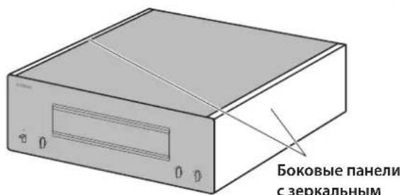
Mirror-finish side panels. 4
Surfaces other than the mirror-finish side panels 4
Part Names and Functions
Front panel 6
Rear panel. 8
Balanced and unbalanced connections 10
Connections
Connecting a preamplifier. 12
Trigger connections. 13
Basic speaker connections. 14
Connecting speaker cables 16
Using standard speaker cables. 16
Using Y-shaped lug cables 17
Bi-wiring connections 18
Bi-amp connections. 20
Bridge connections 22
Connecting the power cord. 24
Reference Materials
General specifications 26
Block diagram 27
Audio characteristics 28
Total harmonic distortion (8Ω). 28
Total harmonic distortion (4Ω). 28
Total harmonic distortion (monaural 8 29
Frequency response 29
Troubleshooting 30
Index 32
Supplied accessories
Please make sure that the following accessories are included in the package.
Power cord
System cable
Owner's Manual (this book)
- Safety Brochure (separate booklet)

WARNING
Do not use the supplied power cord for other devices.
Maintenance
To use this product for an extended period of time, we recommend that you maintain it regularly.

WARNING
- Check the power cord regularly to see if it is dusty. If so, wipe off the dust completely. Otherwise, fire or electric shock might be caused.
- Do not use aerosol or flammable gas spray for cleaning or lubrication. Otherwise, flammable gas will build up inside the unit, causing possible explosion or fire.
NOTICE
- Use a dry soft cloth to clean the unit. Using cleaning agents, such as benzene or thinner, detergent, or chemically-treated cloth might cause color changes or deterioration of the surface. If the surface gets very dirty, damp a cloth with detergent (diluted with water), wring the cloth tightly, and wipe off the dirt.
- If you wipe the surface area in the vicinity of the Yamaha logo with force, the logo might peel off or fiber from the cloth might stick to the surface.
Mirror-finish side panels
We recommend that you use a cleaning cloth such as those made for pianos. If the surface is very dirty, use a soft cloth that is damp with water and wrung tightly.
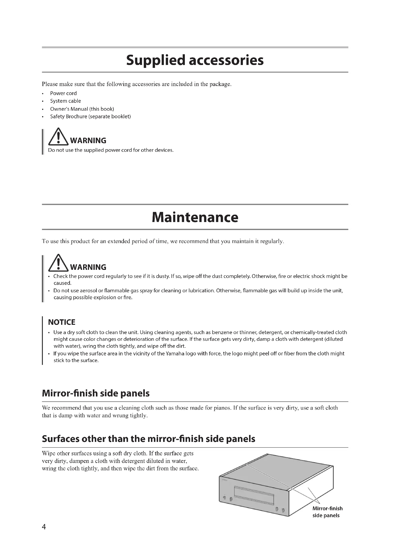
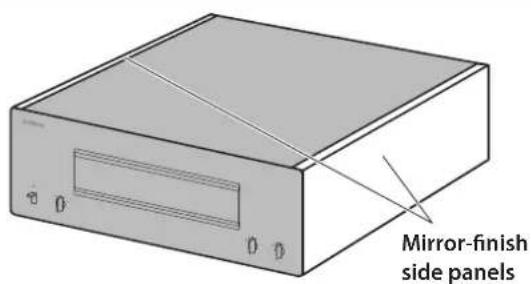
Surfaces other than the mirror-finish side panels
Wipe other surfaces using a soft dry cloth. If the surface gets very dirty, dampen a cloth with detergent diluted in water, wring the cloth tightly, and then wipe the dirt from the surface.
Part Names and Functions
This section describes the names and functions of the parts on the front and rear panel.
Front panel

YAMAHA
NATURAL SOUND POWER AMPLIFIER M-5000
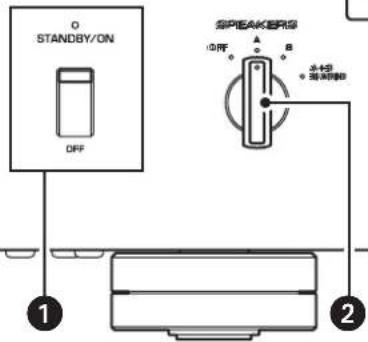
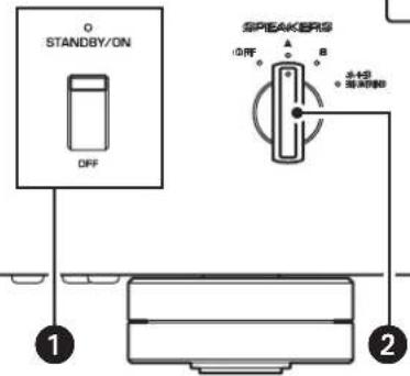
1 STANDBY/ON/OFF (Power) switch/indicator
Turns the power to the unit on or off.
STANDBY/ON: Turns the power to the unit on.
OFF: Turns the power to the unit off.
| Power status Indicator | |
| On mode Lit brightly | |
| Standby mode Lit dimly | |
| Off mode Off |
The unit will enter standby mode in one of the following events:
- If the unit is powered on but not operated for eight hours while the auto power standby function is turned on, or
- If you turn off the power to the device that is connected to this unit's TRIGGER IN jack. For more information, refer to "AUTO POWER STANDBY switch" in the "Rear panel" section (page 9) and to "Trigger connections" (page 13).
Note
After you turn on the unit, it will take a few seconds before the unit can reproduce sound.
NOTICE
If you plan not to use the unit for an extended period of time, be sure to unplug the power cord from the AC outlet. Even when the STANDBY/ON/OFF (Power) switch is turned off (the power indicator is dark), a minimal amount of electric current is still flowing to the unit.

SPEAKERS selector
Turns on or off two sets of speakers connected to the SPEAKERS A and B terminals on the rear panel.
OFF: Both sets of speakers are off.
A: The set of speakers connected to the A terminal is on.
B: The set of speakers connected to the B terminal is on.
A+B/BI-WIRING: Both sets of speakers are on.
NOTICE
Make sure that the impedance of each speaker is appropriate for the system configuration. For more information, refer to "Basic speaker connections" (page 14), "Bi-wiring connections" (page 18), "Bi-amp connections" (page 20), and "Bridge connections" (page 22).
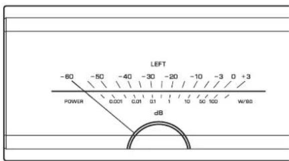
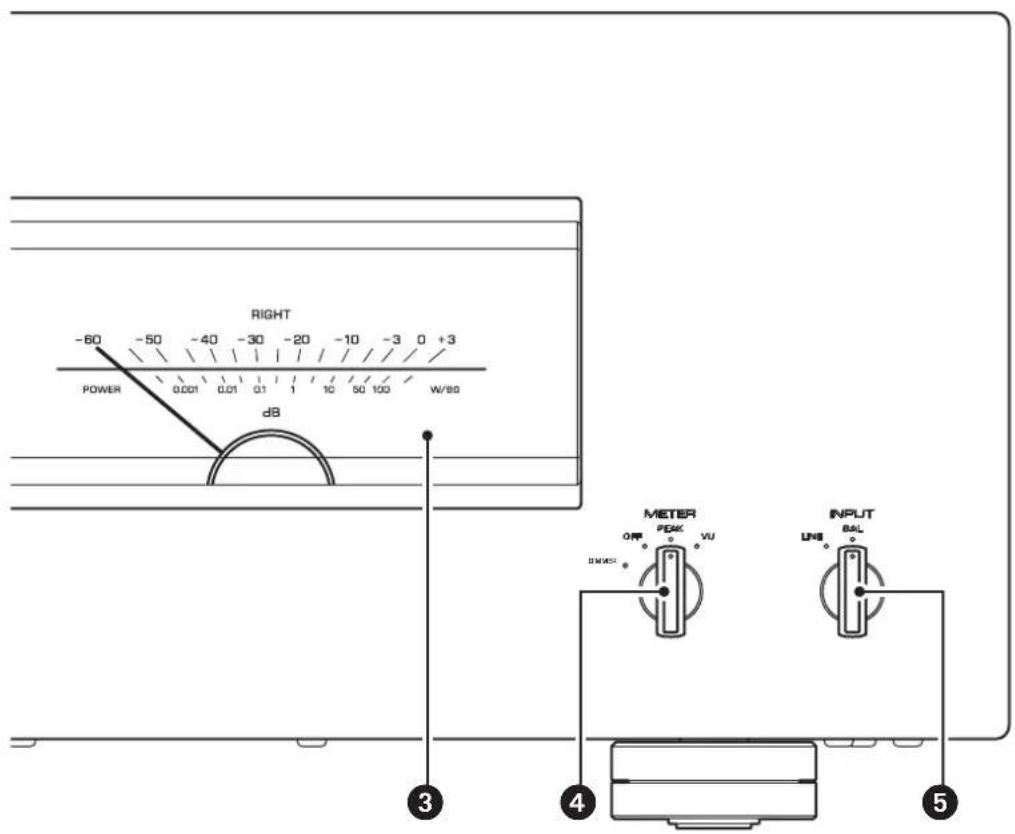
3 Meter display (LEFT/RIGHT)
Indicates the audio output level of the left and right channels.
4 METER selector
Switches the meter display type to OFF, PEAK, or VU.
DIMMER: Adjusts the brightness of the meter display.
The brightness will change slowly between the brightest and darkest (off). When you select the meter type by turning the METER selector, the brightness at that point will be used for the display.
OFF: Turns off meter operation and display illumination.
PEAK: Switches the meter display type to a peak level meter. The peak level meter shows the highest instantaneous level of an audio output signal.
VU: Switches the meter display type to a VU (Volume Unit) level meter. The VU level meter shows an effective audio output value that represents the way sound is perceived by human ears.
INPUT selector
Enables you to select jacks to play back an audio source.
LINE: Audio source input from the LINE jacks will be played back.
BAL: Audio source input from the BAL jacks will be played back.
Rear panel
Note
For information regarding the connection procedure, refer to "Connections" (page 11).
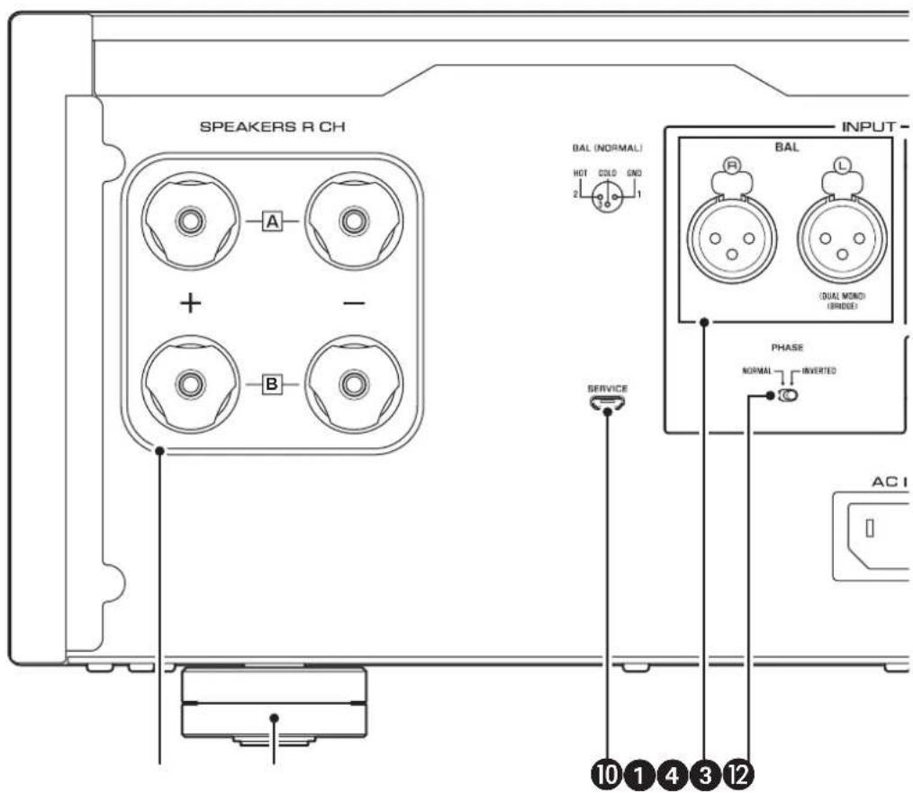
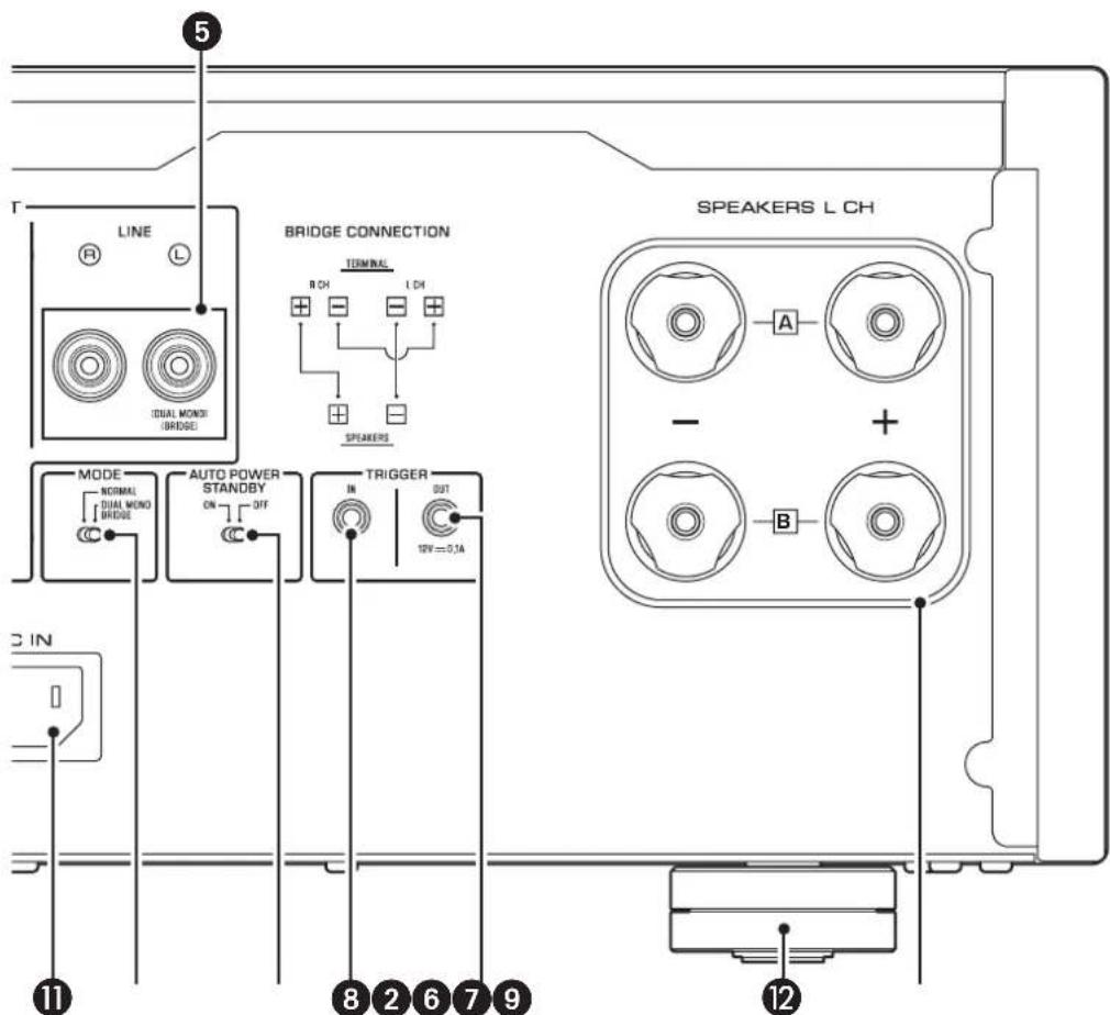
SPEAKERS RCH output terminals
SPEAKERS L CH output terminals
Use the included speaker cables to connect speakers to the terminals. For information regarding the connection procedure, refer to "Connections" (page 11).
BAL input jacks
These are XLR-type balanced input jacks. Connect your preamplifier here. Set the PHASE selector appropriately for the connected preamplifier.
4 PHASE selector
Sets the position (polarity) of the HOT pin at the BAL input jacks according to the connected preamplifier. For more information, refer to "Balanced and unbalanced connections" (page 10).
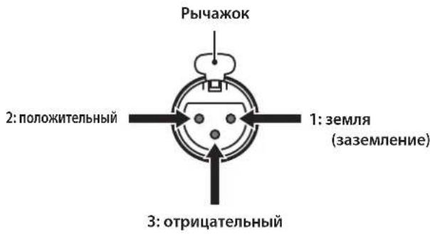
NORMAL: Pin #2 is specified as HOT.
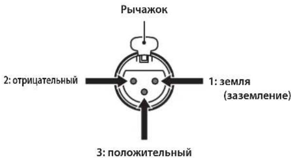
INVERTED: Pin #3 is specified as HOT.
Refer to the instruction manual for the connected component to find out the position of the HOT pin at the balanced output jacks on the component.
LINE input jacks
These are RCA-type unbalanced input jacks. Connect your preamplifier here.

MODE selector
Switches the speaker output between stereo and monaural. For more information, refer to "Basic speaker connections" (page 14), "Bi-wiring connections" (page 18), "Bi-amp connections" (page 20), and "Bridge connections" (page 22).
NORMAL: The unit is used as a stereo amplifier. This is the standard setting.
DUAL MONO/BRIDGE: The unit is used as a monaural amplifier. Select this setting for bi-amp or bridge connections.
7 AUTO POWER STANDBY switch
ON: The unit enters standby mode automatically if it is powered on but not operated for eight hours. This function is disabled if the system cable is connected to the TRIGGER IN jack.
OFF: The unit does not enter standby mode automatically.
8 TRIGGER IN jack
9 TRIGGER OUT jack
Used to connect a component that supports the trigger function so that you can control the unit's power on and off from that component. For more information, refer to "Trigger connections" (page 13).
10 SERVICE jack
This jack is used to test the product.
ACINjack
Connect the supplied power cord here. For more information, refer to "Connecting the power cord" (page 24).
Feet
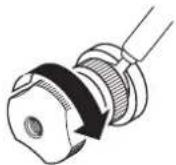
If the unit is unstable, adjust the height of the feet as needed by rotating them.
Balanced and unbalanced connections
This unit features balanced input jacks (BAL) and unbalanced input jacks (LINE).
NOTICE
Do not use balanced and unbalanced connections between two components simultaneously. Doing so would create a ground loop that could generate static and noise.
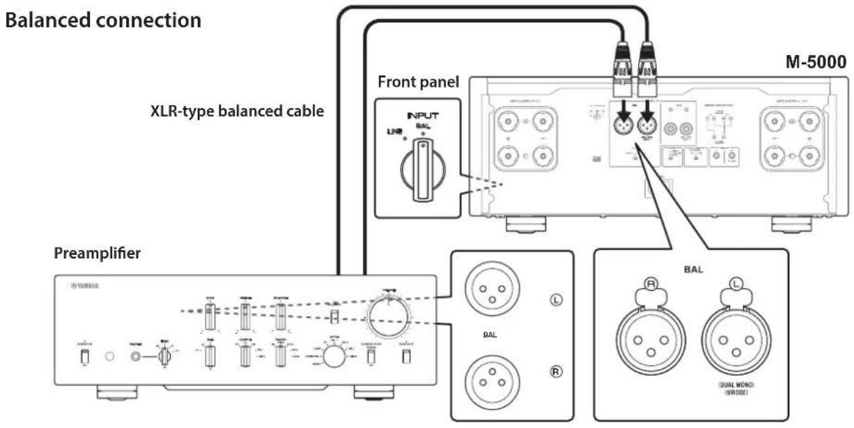
Balanced connection
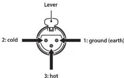
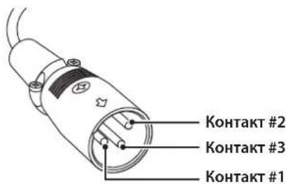
A balanced connection is a great advantage against external noise. For a balanced connection, use a cable with male XLR connectors. When connecting a cable, be sure to align the pins on the connector with the holes on the jack, and then insert the connector into the jack until you hear a click. To remove the cable, while pressing and holding down the lever on the BAL jack, pull out the male XLR connector from the jack.
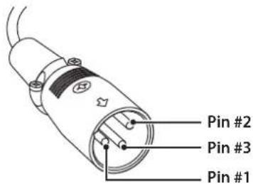
When making a balanced connection, you must set the polarity correctly. To set the polarity, use the PHASE selector on the rear panel.
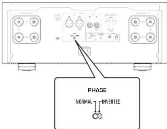
If the PHASE selector is set to NORMAL, pin #2 becomes HOT.
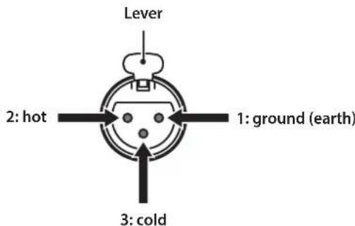
If the PHASE selector is set to INVERTED, pin #3 becomes HOT.
Note
Select NORMAL (pin #2 is HOT) for a Yamaha player or preamplifier.
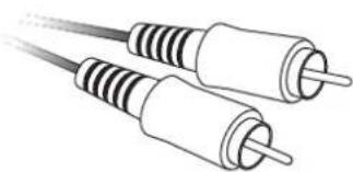
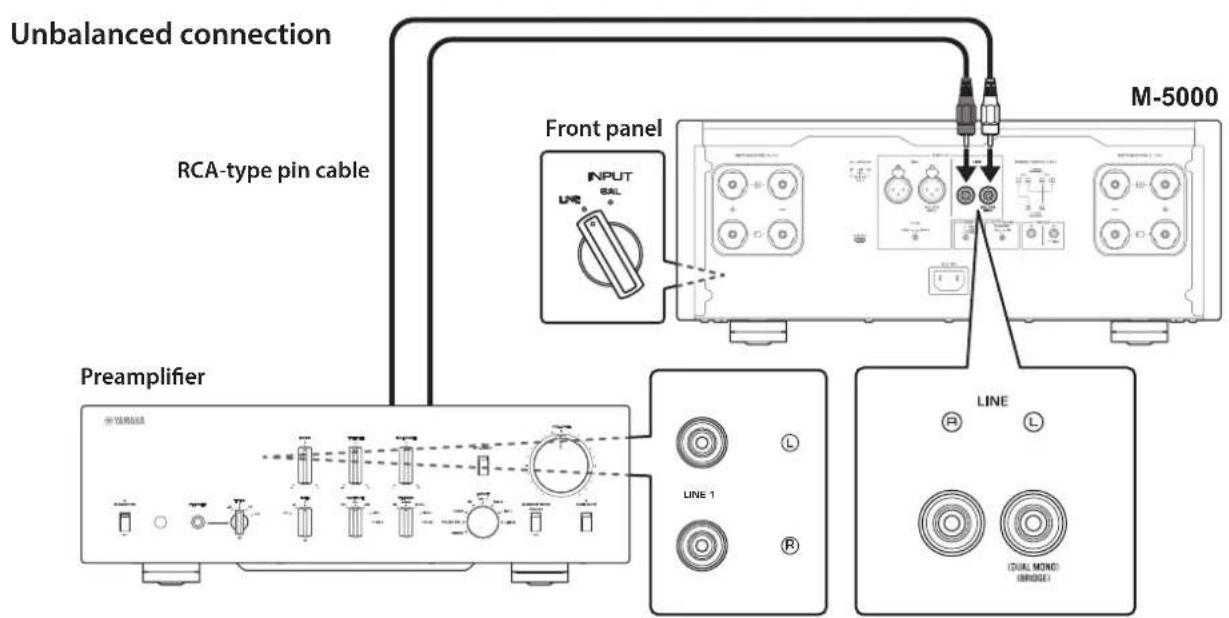
Unbalanced connection
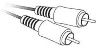
For an unbalanced connection, use RCA-type pin cables. They do not transmit phase information.
Connections
This section explains how to connect the unit to a preamplifier and speakers.

CAUTION
Turn off the power to all components before making any connections.
NOTICE
Before you connect external components, read and follow the instruction manuals for those components. Otherwise, this unit or external components might malfunction.
Connecting a preamplifier
Connect your preamplifier to the unit's input jacks. For this connection, use XLR-type balanced cables or RCA-type unbalanced cables.
NOTICE
The unit's volume level is fixed. Do not connect a component that does not feature volume adjustment to the unit's input jacks. Otherwise, a loud sound might be emitted, resulting in malfunction of the unit or damage to the speakers.
Note
If the preamplifier supports both balanced and unbalanced connections, use a balanced connection.
- Do not use balanced and unbalanced connections between two components simultaneously. Doing so would create a ground loop that could generate static and noise.
Trigger connections
You can control the unit's power on and off in sync with a connected Yamaha component, such as a preamplifier or AV receiver.
Use the supplied system cable to make connections as shown in the following diagram.
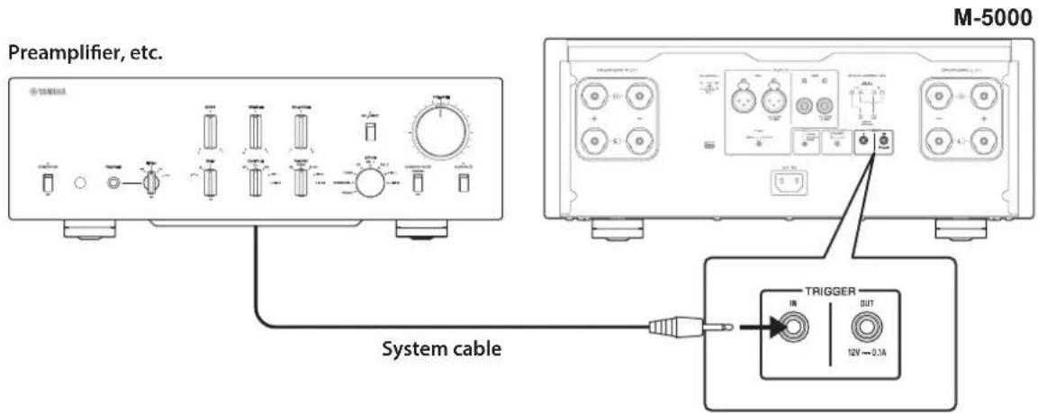
Example (one M-5000 unit is used)
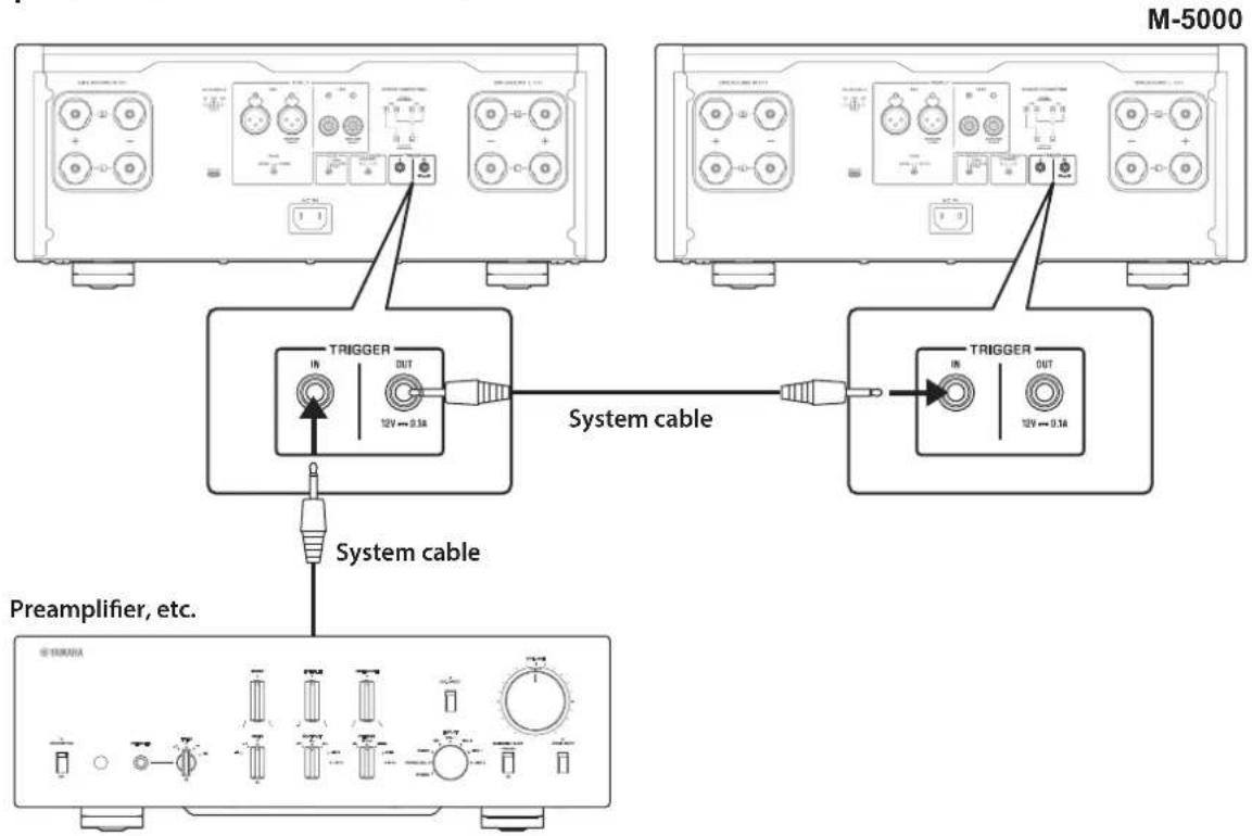
Example (two M-5000 units are used)
To control the unit in a trigger connection configuration, set the STANDBY/ON/OFF (Power) switch to STANDBY/ON.
When the power to the connected component is turned on, the power to this unit is also turned on. When the power to the connected component is turned off, this unit enters standby mode.
Note
When the power switch on this unit is turned OFF, the power to the unit will not be triggered.
Basic speaker connections
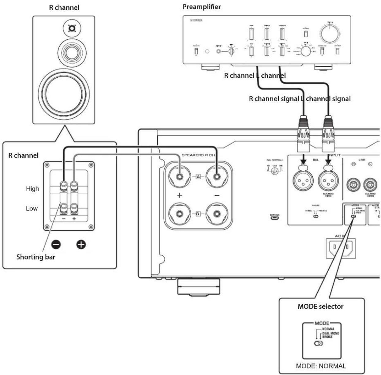
1 Turn off the power to the unit and all connected components.
2 Set the MODE selector on the rear panel to NORMAL.
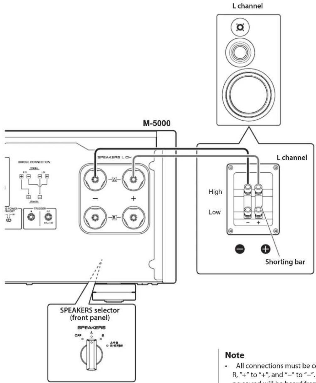
3 Set the SPEAKERS selector on the front panel to A, B, or A+B BI-WIRING.
The diagram shows the selector set to A.
4 Connect the power amplifier to the ^ 一 + " and "terminals of the speakers.

CAUTION
Be sure to use speakers that feature the impedance shown in the table below.
Speaker impedance
| SPEAKERS selector A B A+B | ||
| Basic connection/ Bi-wiring connection | 4Ω or higher 8 | Ω or higher |
| Bi-amp connection 4Ω or higher 8Ω or higher | ||
| Bridge connection 8Ω or higher 16Ω or higher* | ||
- Excluding models for U.S.A. and Canada

CAUTION
Before turning the power back on to the source component, first lower the volume level on that component.
NOTICE
- Do not let the bare speaker wires touch each other, nor let them touch any metal part of this unit. Otherwise, the unit and/or the speakers might be damaged.
- Do not connect an active subwoofer to this unit. Connect the subwoofer to the preamplifier.
Note
- All connections must be correct: L (left) to L, R (right) to R, "+" to "+" and "-" to "-" If the connections are faulty, no sound will be heard from the speakers. Also, if the polarity of the speaker connections is incorrect, the sound will be unnatural and lack bass.
-
Because this power amplifier is of the floating balanced type, the following types of connections are not possible.
-
Connecting between two "+" (or two -") terminals of the left and right channels (Fig. 1).
-
Connecting each "--" terminal of the unit's left and right channels to the opposite channel speakers (cross connection, Fig. 2).
- Connecting the left/right channel "--" terminals (or accidentally allowing them to come in contact) with the metal part of the rear panel of this unit.
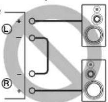
Figure 1
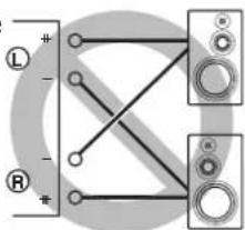
Figure 2
Connecting speaker cables
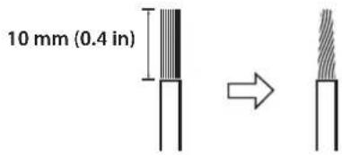
Using standard speaker cables
1 Remove approximately 10mm (0.4 in) of insulation from the end of each speaker cable, and twist the exposed wires together tightly to prevent short circuits.
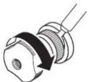
2 Unscrew the knob on each SPEAKERS terminal, and then insert the bare wire into the side hole on the terminal.
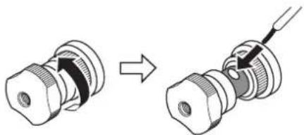
Diameter of the speaker cable wire hole: 6.0mm (0.24 in)
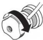
3 Tighten the knob.
CAUTION
- Do not loosen the knob excessively. Otherwise, the knob might come off and a child might swallow it accidentally.
To reduce the risk of electric shock, do not touch the SPEAKERS terminals while the power to the unit is on.
NOTICE
If the SPEAKERS terminals come into contact with a metallic rack, a short circuit might occur, resulting in damage to this unit. When installing the unit in a rack, maintain a sufficient clearance to prevent the SPEAKERS terminals from coming into contact with the rack.
Using Y-shaped lug cables
1 Unscrew the knob, and then sandwich the Y-shaped lug between the ring part and base of the terminal.
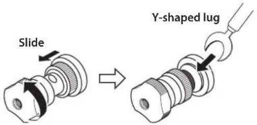
Thickness of the terminal core: 5.0mm (0.20 in)
2 Tighten the knob.
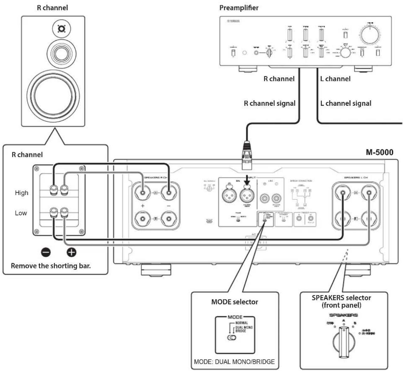
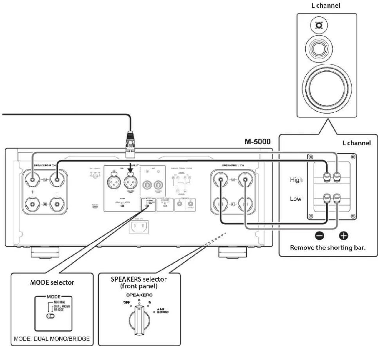
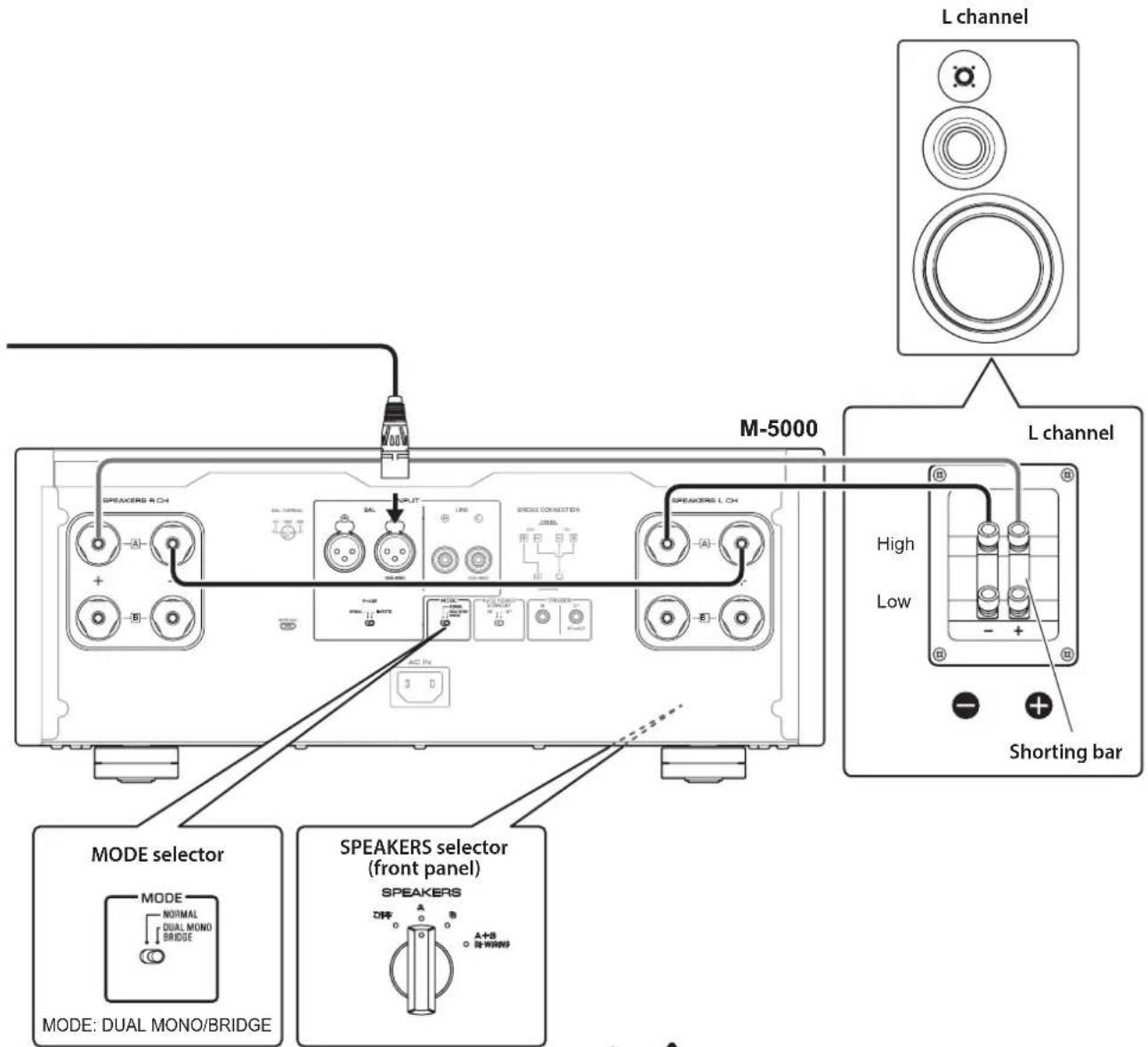
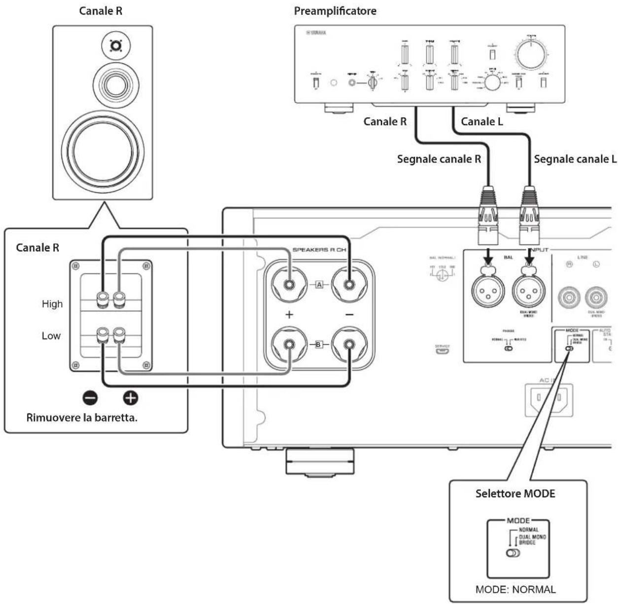
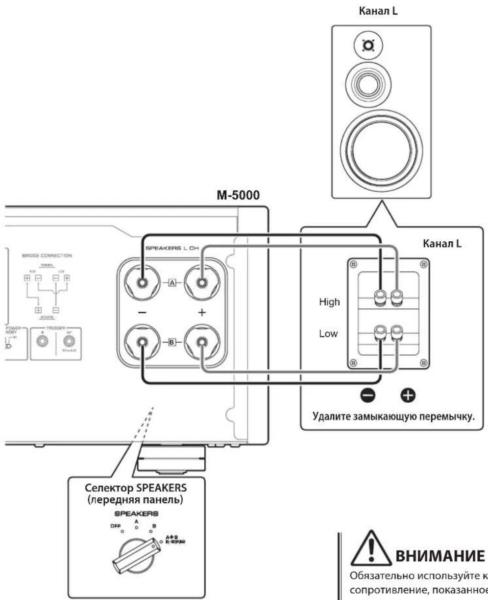
Bi-wiring connections
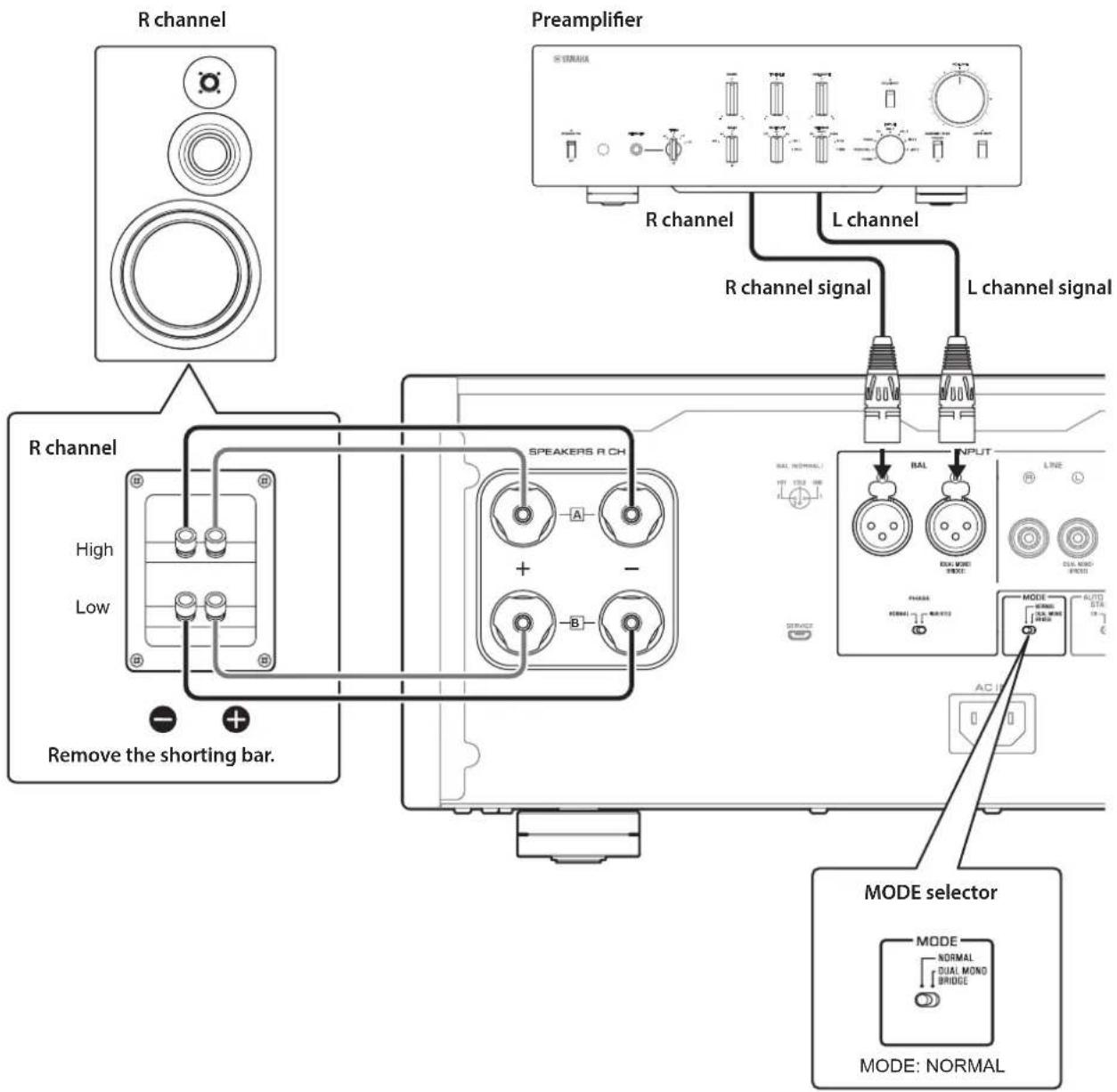
To bi-wire your speakers, separate cables are used to connect the mid/high-frequency speaker driver (tweeter) and the low-frequency driver (woofer) on each biwireable speaker to the amplifier. Running separate cables from the amplifier can have a profound impact on relieving the tweeter circuit from the back flush of EMF (electromotive force) generated by the woofer's voice coil, resulting in less interference between HF and LF ranges and better sound quality.
You need to use speakers that feature two sets of terminals (total of four) that allow each speaker to be split into two sections (low-frequency and mid/high-frequency ranges).
1 Turn off the power to the unit and all connected components.
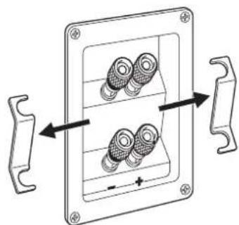
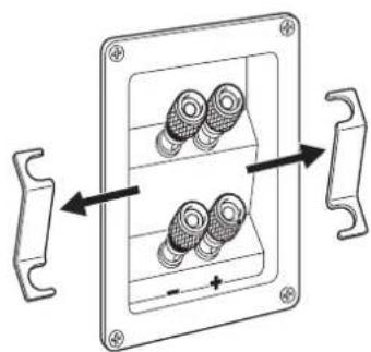
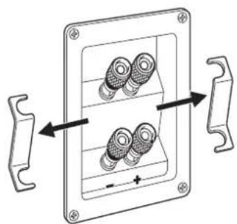
2 Remove the shorting bars or bridges on the speakers.
The LPF (low pass filter) and HPF (high pass filter) crossovers will be separated.
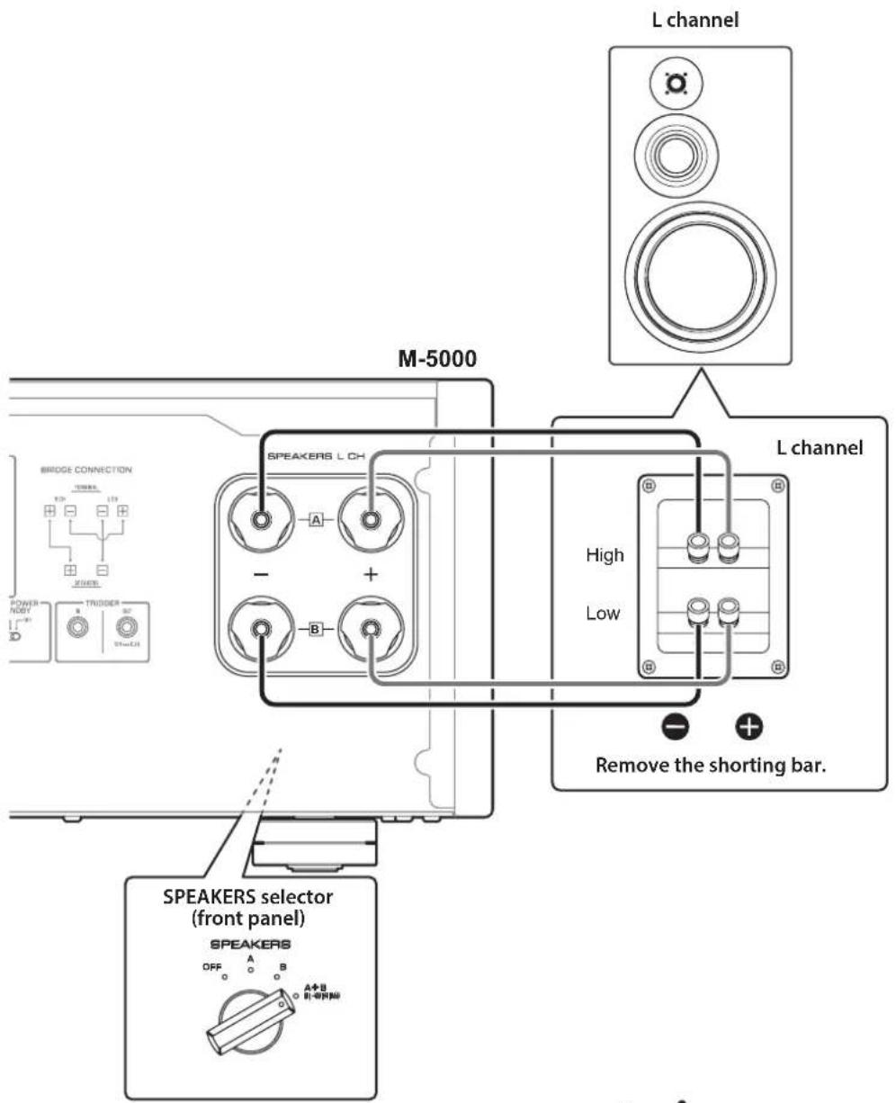
3 Connect the power amplifier to the speakers.
For each channel speaker, connect the cables from the speaker's mid/high range terminals to the amplifier's SPEAKERS A jacks of the corresponding channel, and from the speaker's low range terminals to the amplifier's SPEAKERS B jacks of the corresponding channel respectively.
4 Set the MODE selector on the rear panel to NORMAL.
5 Set the SPEAKERS selector on the front panel to A+B BI-WIRING.

CAUTION
Be sure to use speakers that feature the impedance shown in the table below.
Speaker impedance
| SPEAKERS selector A B | A+B | ||
| Basic connection/ Bi-wiring connection | 4Ω or higher 8Ω or higher | ||
| Bi-amp connection 4Ω or higher 8Ω or higher | |||
| Bridge connection 8Ω or higher 16Ω or higher* | |||
- Excluding models for U.S.A. and Canada

CAUTION
Before turning the power back on to the source component, first lower the volume level on that component.
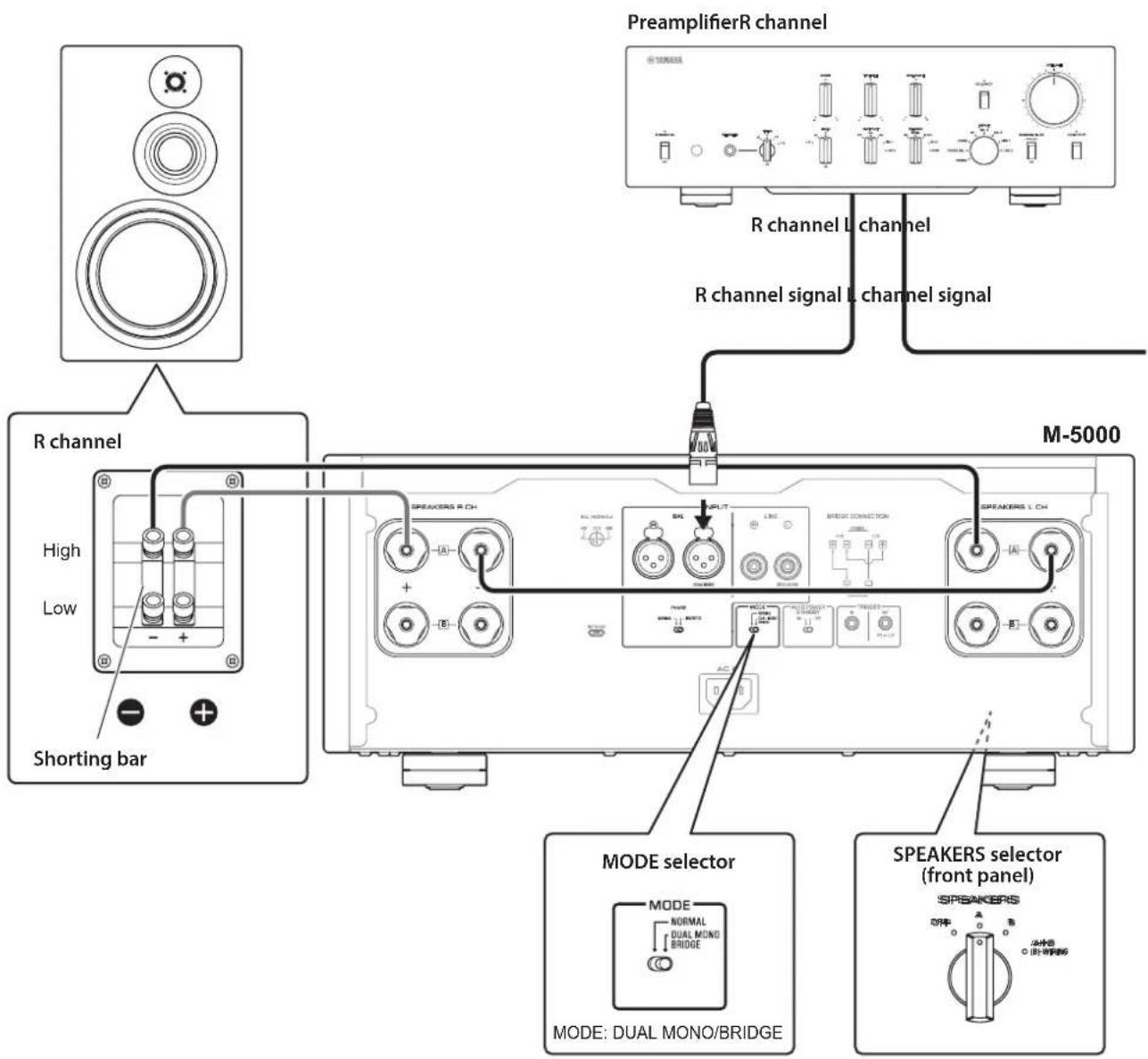
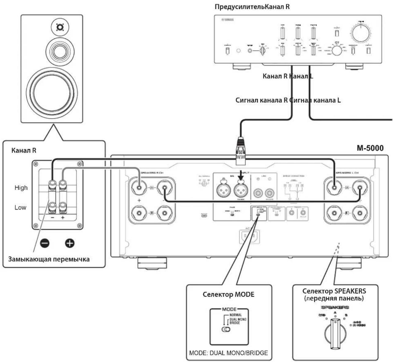
Bi-amp connections
To configure a bi-amp stereo system, you need two M-5000 units.
The M-5000 features two built-in amplifiers. Each of these amps is connected to the mid/high-frequency speaker driver (tweeter) and the low-frequency driver (woofer) on the speaker of the corresponding channel. You need to use speakers that feature two sets of terminals (total of four) that allow each speaker to be split into two sections (low-frequency and mid/high-frequency ranges). Bi-amping speakers can prevent the back flush of EMF (electromotive force) generated by the woofer from affecting the signal, resulting in improved sound quality in some cases.
Connect the input source to the L-channel input jacks on both M-5000 units.
1 Turn off the power to the unit and all connected components.
2 Remove the shorting bars or bridges on the speakers.
The LPF (low pass filter) and HPF (high pass filter) crossovers will be separated.
3 Set the MODE selector on the rear panel to DUAL MONO/BRIDGE.
4 Set the SPEAKERS selector on the front panel to A, B, or A+B BI-WIRING.
The diagram shows the selector set to A.
5 Connect the power amplifier (this unit) to the speakers.
For each channel speaker, connect the cables from the speaker's mid/high range terminals to the amplifier A jacks for the SPEAKERS R CH, and from the speaker's low range terminals to the amplifier A jacks for the SPEAKERS L CH.

CAUTION
Be sure to use speakers that feature the impedance shown in the table below.
Speaker impedance
| SPEAKERS selector A B | A+B | ||
| Basic connection/ Bi-wiring connection | 4Ω or higher 8Ω | or higher | |
| Bi-amp connection 4Ω | or higher 8Ω or higher | ||
| Bridge connection 8Ω or higher 16Ω or higher* | |||
- Excluding models for U.S.A. and Canada

CAUTION
Before turning the power back on to the source component, first lower the volume level on that component.
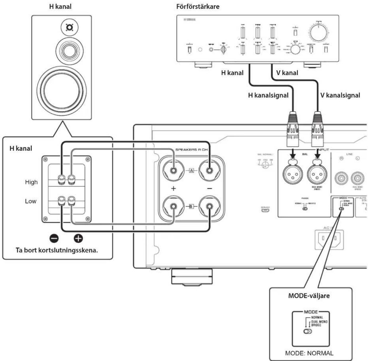
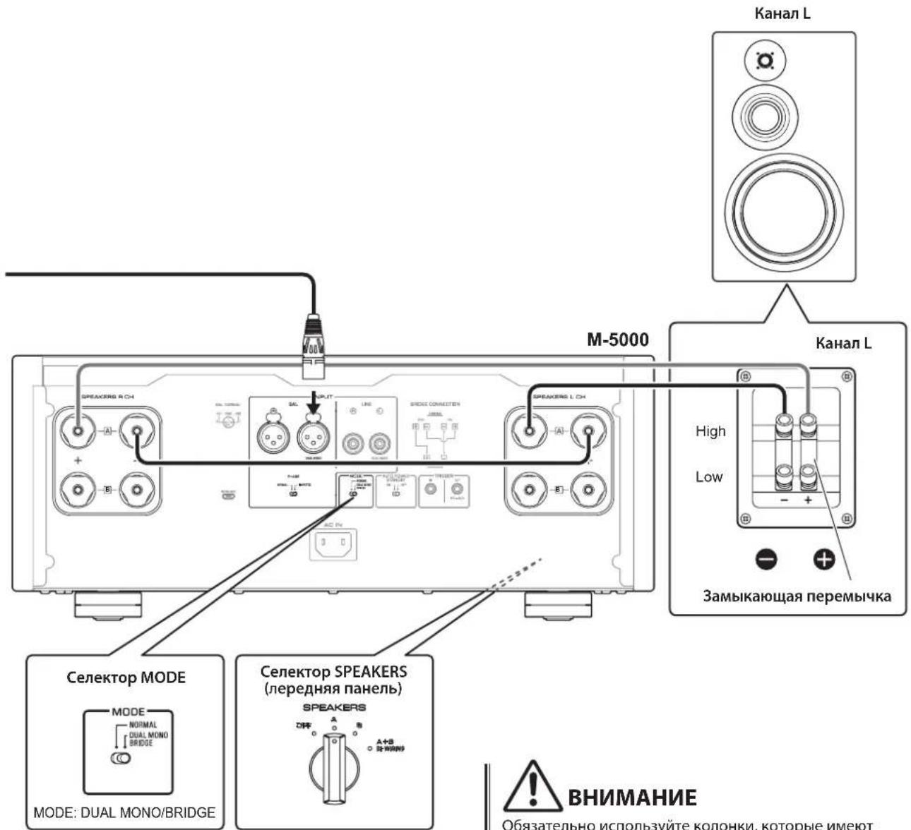
Bridge connections
In a bridge connection configuration, the M-5000 is used as a monaural amplifier. To create a stereo system, you need two M-5000 units.
On each amplifier, connect the "+" terminal of the SPEAKERS L CH to the "−" terminal of the SPEAKERS R CH. For this connection, use a cable that features the same material as the speaker cables, and a length of 1.0m or less and a cross-sectional area of 1.0mm^2 or larger. Do not bundle the cable.
Connect the input source to the L-channel input jacks on both M-5000 units.
NOTICE
Since amplification will be doubled in this configuration, adjust the volume level appropriately on the connected preamplifier. If you are using a Yamaha preamplifier that features a GAIN selector, adjust the volume level using this selector so that you will be able to use volume controls on other components in the usual way.
1 Turn off the power to the unit and all connected components.
2 Set the MODE selector on the rear panel to DUAL MONO/BRIDGE.
3 Set the SPEAKERS selector on the front panel to A, B, or A+B BI-WIRING.
The diagram shows the selector set to A.
4 On each amplifier, connect the ^ 十 + ^ 一 terminal of the SPEAKERS L CH to the ^ 一 - ^ 一 terminal of the SPEAKERS R CH.
5 Connect the "+" terminal of the SPEAKERS R CH to the speaker's "+" terminal, and the "-" terminal of the SPEAKERS L CH to the speaker's "-" terminal.

CAUTION
Be sure to use speakers that feature the impedance shown in the table below.
Speaker impedance
| SPEAKERS selector A B | A+B | ||
| Basic connection/ Bi-wiring connection | 4Ω or higher 8Ω or higher | ||
| Bi-amp connection 4Ω or higher 8Ω or higher | |||
| Bridge connection 8Ω or higher 16Ω or higher* | |||
- Excluding models for U.S.A. and Canada

CAUTION
Before turning the power back on to the source component, first lower the volume level on that component.
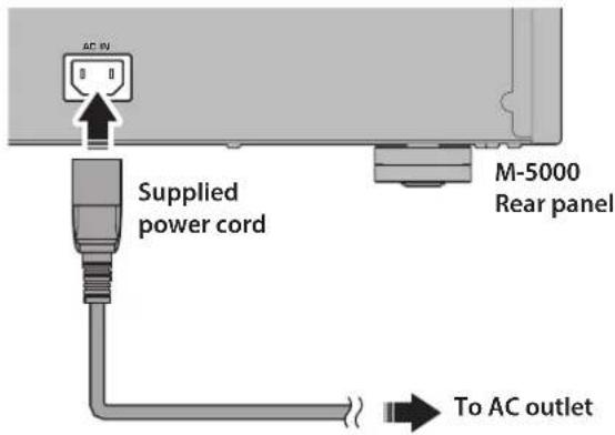
Connecting the power cord
After all connections are complete, make sure that the STANDBY/ON/OFF (Power) switch is turned off, then plug the power cord into the AC IN connector of the unit, and then plug the power cord into the AC outlet.

WARNING
If you notice any of the following abnormal conditions, turn off the power to the unit immediately, and disconnect the power plug from the AC outlet.
- The power cord or plug is damaged.
- The unit is emitting odor, strange noise, or smoke.
Liquid has been spilled or objects have fallen into the unit.
Sound is muted all of a sudden during the operation. - The unit is cracked or damaged.
Otherwise, continued use of the unit might lead to electric shock, fire, or malfunction. Contact your nearest Yamaha dealer or service center for check-up or repair.
- Do not touch the power cord or plug during lightning storms. Otherwise, an electric shock might be caused.
- Be sure to use a power outlet with the power voltage labeled on the unit. If the unit is plugged into an outlet of an inappropriate voltage, fire, electric shock, or malfunction might be caused.
Use only the supplied power cord. Do not use the supplied power cord for other devices. Otherwise, fire, burning, or malfunction might be cause - Plug the unit into an AC outlet that is clearly visible and easily reached, so that you can unplug the unit easily and quickly from the AC outlet in case of emergency. Even when the power switch is turned off, a minimal amount of electric current is still flowing to the unit, unless you unplug the unit from the AC outlet.
If a lightning storm is approaching, turn off the power to the unit immediately, and disconnect the power plug from the AC outlet. Otherwise, fire or malfunction might be caused.
If you plan not to use the unit for an extended period of time, be sure to unplug the power cord from the AC outlet. Otherwise, fire or malfunction might be caused.

CAUTION
- Do not use an AC outlet that is so loose that the plug does not stay firmly in place. Otherwise, fire, electric shock, or burning might be caused.
- When disconnecting the power cord from the AC outlet, grasp the plug; do not pull the cord. Otherwise, the power cord may be damaged, causing an electric shock or fire.
- Insert the power plug into the AC outlet all the way firmly. If the plug is not inserted completely, use of the unit might cause an electric shock. Or, dust might build up on the plug, causing fire or burning.
NOTICE
If you plan not to use the unit for an extended period of time, be sure to unplug the power cord from the AC outlet. Even when the STANDBY/ON/OFF (Power) switch is turned off (the power indicator is dark), a minimal amount of electric current is still flowing to the unit.
Reference Materials
General specifications
Rated output power (20 Hz to 20 kHz, 0.07% THD)
2-channel driven, 8Ω. 100 W + 100 W
2-channel driven, 4 200 W + 200 W
Driven in monaural, 8Ω. 400 W
Dynamic power
8Ω 125W+125W
6Ω 170W+170W
4Ω 250W+250W
2Ω 500W+500W
Maximum output power (1 kHz, 0.7% THD)
[Models for U.K. and Europe]
4Ω 220W+220W
IEC output power (1 kHz, 0.02% THD)
[Models for U.K. and Europe]
8Ω 125W+125W
Maximum effective output power
(JEITA, 1 kHz, 10% THD)
[Models for China, Korea, U.K., Asia, Central and South America, and Taiwan]
8Ω 135W+135W
4Ω 270W+270W
Power bandwidth (MAIN L/R, 0.1% THD, 45 W)
8Ω 10 Hz to 50 kHz
Damping factor (1 kHz)
8Ω 300
Input sensitivity/input impedance (1 kHz, 100 W/8Ω)
BAL. 2.0 Vrms/47 kΩ
LINE. 1.0 Vrms/47 kΩ
Maximum input signal voltage (1 kHz, 0.5% THD)
BAL. 2.20 Vrms
LINE 1.10 Vrms
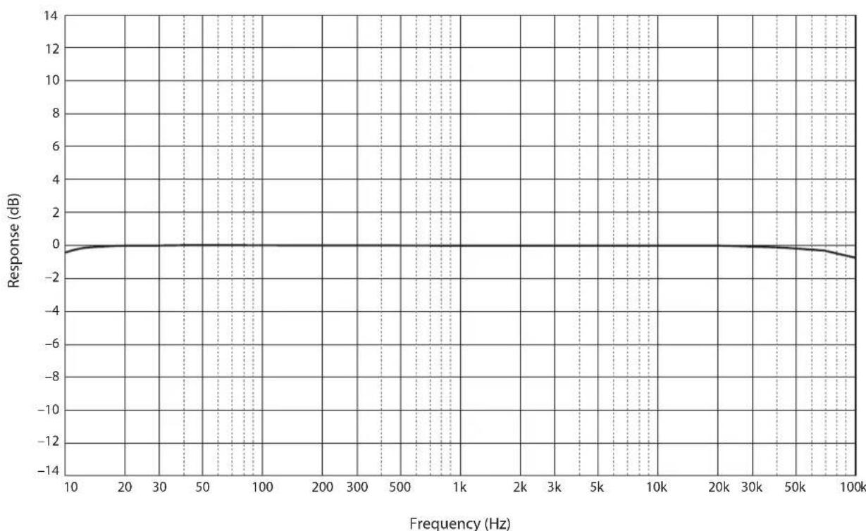
Frequency response
5Hz to 100kHz +0 / - 3 dB
20Hz to 20kHz +0 / - 0.3 dB
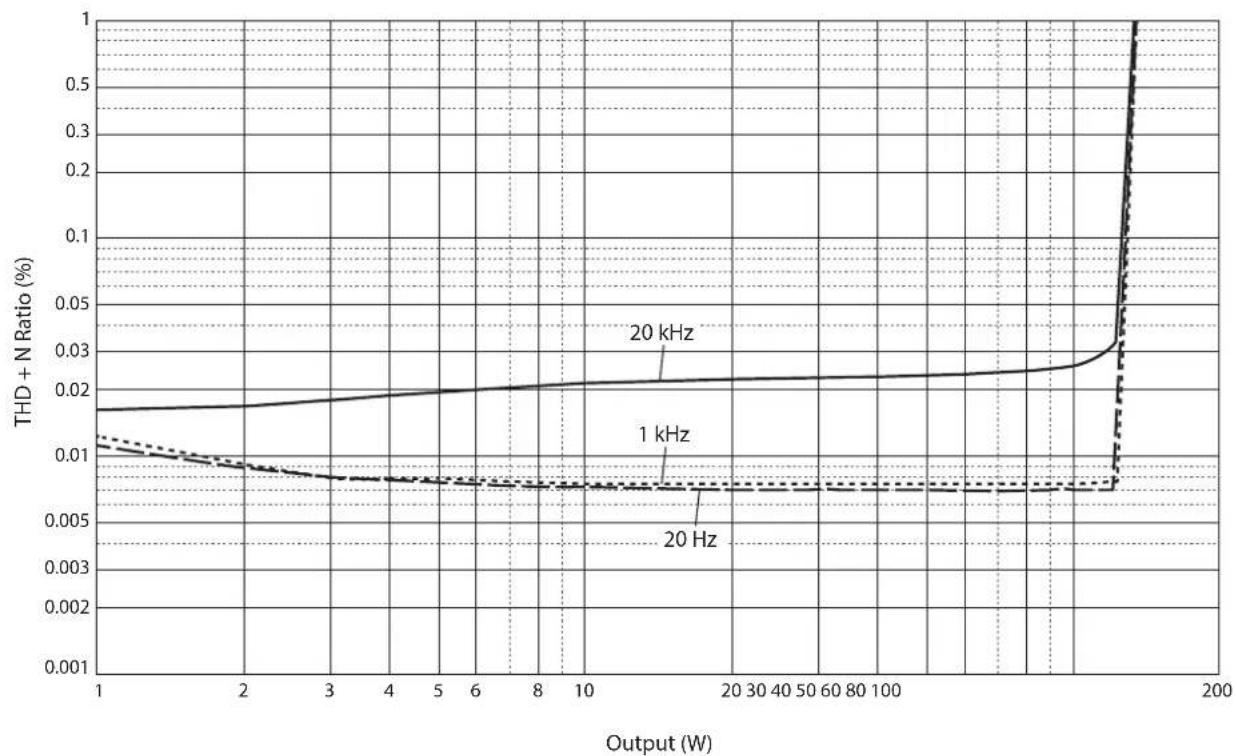
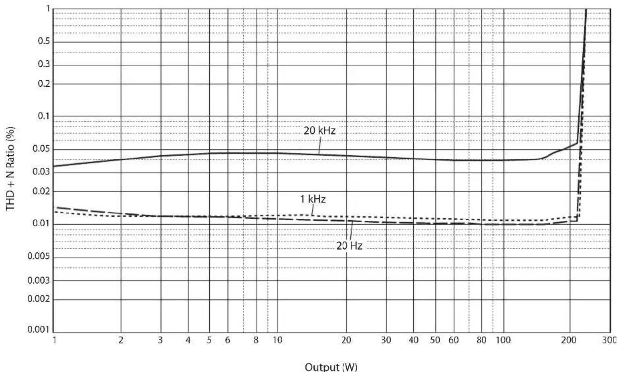
Total harmonic distortion plus noise (20 Hz to 20 kHz)
2-channel driven,
LINE to SPEAKERS, 50 W/8Ω .0.035%
2-channel driven,
BAL to SPEAKERS, 50 W/8Ω. .035%
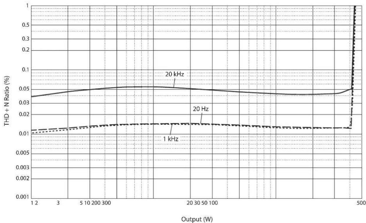
Driven in monaural,
LINE to SPEAKERS, 200 W/8Ω .0.05%
Driven in monaural,
BAL to SPEAKERS, 200 W/8Ω. 0.05%
Channel separation (Input 1.0k terminated)
1 kHz/10 kHz ≥90 dB/≥70 dB
Signal to noise ratio (IHF-A network, input 1.0k shorted, reference level 200 W/4Ω)
110 dB
Residual noise (IHF-A network)
BAL. 40~ V rms
LINE. 50~ Vrms
Meter accuracy
Class 2.5
Power supply
[Models for U.S.A. and Canada]. . AC 120 V, 60 Hz
[Model for China] AC 220 V, 50 Hz
[Model for Korea] .AC 220 V,60 Hz
[Model for Australia]. AC 240 V, 50 Hz
[Models for U.K. and Europe] . . . AC 230 V, 50 Hz
[Model for Asia] . . . . AC 220-240 V, 50 Hz/60 Hz
[Models for Central and South America,
and Taiwan] .AC 110 V,60 Hz
Powerconsumption
400W
Standbypowerconsumption
Off modc 0.1 W
Standby mode 0.2 W
Maximum power consumption (1 kHz, 4Ω 10% THD)
[Models for Central and South America, and Taiwan] 800 W
Dimensions (× × )
435× 180× 464mm
Weight
26.9 kg
- The contents of this manual apply to the latest specifications as of the publishing date. To obtain the latest manual, access the Yamaha website then download the manual file.
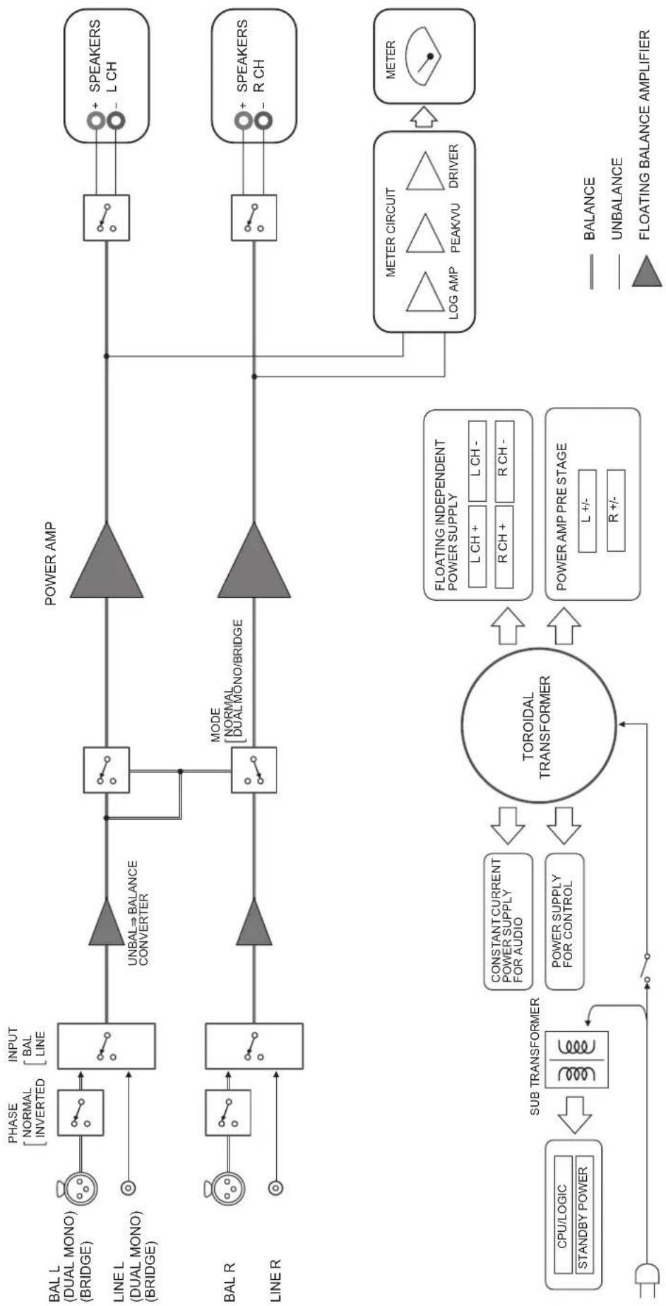
Block diagram
Audio characteristics

Total harmonic distortion (8Ω)

Total harmonic distortion (4Ω)
Total harmonic distortion (monaural 8

Frequency response

Troubleshooting
Refer to the table below if this unit does not function properly. If the instructions below do not help, or if the problem you are experiencing is not listed below, turn off the unit, disconnect the power cord, and contact the nearest authorized Yamaha dealer or service center.
| Problem Cause Remedy | See page | ||
| Power does not turn on. | The power cord is not connected to the AC IN connector on the rear panel or is not plugged into an AC outlet. | Connect the power cord firmly. 24 | |
| The protection circuitry has been activated because of a short circuit, etc. | Make sure that the speaker wires are not touching each other or shorting out against the rear panel of the unit, and then turn on the power to the unit. | 16 | |
| The unit has been exposed to a strong external electric shock (such as lightning or strong static electricity). | Turn off the unit, disconnect the power cord from the AC outlet, wait for about 30 seconds, and then plug the unit in again. | 24 | |
| The STANDBY/ON indicator on the front panel flashes. | The protection circuitry has been activated because of a short circuit, etc. | Make sure that the speaker wires are not touching each other or shorting out against the rear panel of the unit, and then turn on the power to the unit. | 16 |
| There is a problem with the internal circuitries of this unit. | Disconnect the power cord from the AC outlet and contact the nearest authorized Yamaha dealer or service center. | 24 | |
| The unit is turned on but no sound is heard. | The protection circuitry has been activated because of a short circuit, etc. | Make sure that the speaker wires are not touching each other or shorting out against the rear panel of the unit, and then turn on the power to the unit. | 16 |
| The SPEAKERS selector is set to OFF. | Set the SPEAKERS selector to the appropriate position. | 6 | |
| The speaker cables are not connected properly. | Make sure that the speaker cables are connected properly. | 16 | |
| The INPUT selector setting does not match the connected input source. | Select an appropriate input source with the INPUT selector on the front panel. | 12 | |
| The sound is suddenly muted. | The protection circuitry has been activated because of a short circuit, etc. | Make sure that the speaker wires are not touching each other or shorting out against the rear panel of the unit, and then turn on the power to the unit. | 16 |
| The speakers are not connected properly. | Make sure that the speakers are connected properly. If the problem persists, the cables might be defective. | 16 | |
| There is a lack of bass and no ambience. | The + and - wires are connected in reverse at the amplifier or the speakers. | Connect the speaker wires to the correct + and - polarity. | 15 |
| A “humming” noise is heard. | Both balanced and unbalanced cables are being used simultaneously between two components. | Do not use both balanced and unbalanced cables simultaneously between two components. Doing so would create a ground loop that could generate static and noise. | 12 |
Index
A
AUTO POWER STANDBY switch 9
B
Balanced connection 10
Balanced input jack 12
BAL input jack 12
Bi-amp connection 20
Bi-wiring connection 18
Bridge connection 22
C
Connecting a preamplifier 12
Connecting the speaker cables. 16
Connecting the speakers 14
F
Feet 9
1
INPUT selector 12
L
LINE input jack 12
M
METER selector 7
MODE selector 9
P
PHASE selector 10
Power cord 24
Power indicator 6
Power switch 6
5
SERVICE jack 9
SPEAKERS selector 6
STANDBY/ON/OFF indicator 6
STANDBY/ON/OFF switch 6
T
Trigger connection 13
TRIGGER jack 13
Turning the power on 6
U
Unbalanced connection 10
Y
Y-shaped lug cable 17
Français
https://download.yamaha.com/
Fonctions
LINE. 1,0 Vrms/47 kΩ
LINE vcrs SPEAKERS, 200 W/8Ω .05%
Excite en mono,
BAL vers SPEAKERS, 200 W/8Ω .05%
1 kHz/10 kHz ≥90 dB/≥70 dB
(JEITA, 1 kHz, 10% THD)
BAL. 2,0 Vrms/47 kΩ
LINE. 1,0 Vrms/47 kΩ
Frequenzgang
1 kHz/10 kHz ≥90 dB/≥70 dB
https://download.yamaha.com/
Funktioner
Bi-wiring-ansluttingar
(JEITA, 1 kHz, 10% THD)
LINE. 1,0 Vrms/47 kΩ
Maximal signalspanning vid ingang (1 kHz, 0,5% THD)
BAL. 2,20 Vrms
LINE 1,10 Vrms
Frekvensætergivning
5 Hz till 100 kHz. +0/-3 dB
20 Hz till 20 kHz. +0/-0,3 dB
Total harmonisk distorsion plus brus (20 Hz till 20 kHz)
2-kanalsdriven,
LINE till SPEAKERS, 50W / 8 . .035%
2-kanalsdriven,
BAL till SPEAKERS, 50 W/8Ω .035%
Driven i mono,
LINE till SPEAKERS, 200 W/8Ω. .05%
Driven i mono,
BAL till SPEAKERS, 200 W/8Ω .0.05%
Kanalseparation (Ingang 1,0 kΩ avslutad)
1 kHz/10 kHz ≥90 dB/≥70 dB
Signal till brusforhallande (IHF-A natverk, ingang
1,0 kΩ kortslutet, referensniva 200 W/4Ω)
110 dB
Restbrus (IHF-A natverk)
BAL. 40~ V rms
LINE. 50~ Vrms
Mätnoggrannhet
Klass 2.5
Strömförsörning

Total harmonisk distorsion (8Ω)

Total harmonisk distorsion (4Ω)
Total harmonisk distorsion (mono 8Ω)

Frekvensætergivning

Felsökning
STANDBY/ON/OFF-knapp 102
Strömbrytaren 102
Strömindikatorn 102
Stromsladd 120
T
Trigger-anslutining 109
TRIGGER-uttag 109
https://download.yamaha.com/
Caratteristiche
Collegamenti bi-wire
(JEITA, 1 kHz, 10% THD)
da BAL a SPEAKERS, 50 W/8Ω .035%
Mono,
da LINE a SPEAKERS, 200 W/8Ω .05%
Mono,
da BAL a SPEAKERS, 200 W/8Ω . . . . . . . . . . . . . . . . . . . . . . . . . . . . . . . . . . . . . . . . . . . . . . . . . . . . . . . . . .
1 kHz/10 kHz ≥90 dB/≥70 dB
Rumore residuo (rete IHF-A)
BAL. 40~ V rms
LINE. 50~ V rms
Bi-wire, Collegamento 146
C
https://download.yamaha.com/
Funciones
(JEITA, 1 kHz, 10% THD)
LINE. 1,0 Vrms/47 kΩ
LINE a SPEAKERS, 50 W/8Ω. .035%
BAL a SPEAKERS, 50 W/8Ω .035%
Dirigida en monaural,
LINE a SPEAKERS, 200 W/8Ω. 0,05%
Dirigida en monaural,
BAL a SPEAKERS, 200 W/8Ω 0.05%
1 kHz/10 kHz ≥90 dB/≥70 dB
Rudo residual (red IHF-A)
BAL. 40 μVrms
LINE. 50~ V rms
https://download.yamaha.com/
Eigenschappen
NORMAL: Pin #2 is HOT.
INVERTED: Pin #3 is HOT.
(JEITA, 1 kHz, 10% THD)
LINE. 1,0 Vrms/47 kΩ
Maximaal voltage ingangssignaal (1 kHz, THD 0,5%)
BAL. 2,20 Vrms
LINE 1,10 Vrms
Frequentierresponds
5 Hz tot 100 kHz +0/-3 dB
20 Hz tot 20 kHz. +0/-0,3 dB
1 kHz/10 kHz ≥90 dB/≥70 dB
Signaal/ruis-verhouding (IHF-A-network, ingang 1,0 kΩ shorted, referentie niveau 200 W/4Ω)
110 dB
Restruis (IHF-A-network)
BAL. 40~ V rms
LINE. 50~ Vrms
Meteraccuratesse
klasse 2.5
Stroomvoorziening
https://download.yamaha.com/
Функцин
IJIaBAIOHaa H CHMMETPNHHa NcpcdaHa oT BBOJa IO BBIOHa cHrHaJa
OueHb KpeIIKNe pyuKN IIpeKJIIOueHHa
YcToHbA MExaHHueckKa KOHCTpyKIIH OCHOBaHH 3HaHTeJIbHO yMeHbIaET BJIHHe BHeIIHX Bn6paui
CHMMETPnHbI H3aH CJeBOH npaBOH cTopoHbI
BIOK IINTAHN 6OJIbIIOH MOIHOCTH C HeTbIPbMg OTJEJBHbIMN KOHTypaMH H KOHNHeHCATOpaMH 6OJIbIIOH cMKoCTH 33000 MKΦ × 4
HOBBINH3aHHOJKB BHNICMCHbIX IIHHIOB
MoiHbI BbIXoHOH CHHaJI 400 BT/8 OM B MOHOOHNueCKOM peKHM
O daHHOM pyKOBoDCTBe
HIIIOCTpaHHN BaHHOM pyKOBOCTBE IIpeIcTaBHeHbTOJIbKO B O3HaKOMHTeJIbHbIX IeJIAX.
Ha3BaHHaKOMIIaHHH IN pOdyKTOB B pyKOBOCTBE ABJIOCTc TOBapHBIMN 3HaKaAMn HJIH 3apeHCTpHPOBAHHbIMN TOBapHBIMN 3HaKaAMn NX COOTBeTCTBYOIIHX BJaDEJIbIeB.
“! PPEyPExEHEHNE" 6o3Haayet Mepy IpeocTopoxHoCTH, KOToPbIe cJeUyET co6IOaTb, TTO6bI H36eKaTb PNcKa CMePTH HIN cepBe3HOITpaBMbl.
BHUMAHUE" 0603Haayet Mepy IpeIOcTOPOJHOCTH, KOToPbIe cJIeIyET co6JIHOaTb, TTO6bI H36eKaTb pNcKa TpaBMbl.
"YBEDOMJHEHNE" 063Haayet Mepy IpeIOCTOPoXHOCTH, KOToPbIe CJIeIyET CO6IIHOaTB, YTO6bI H36eKaTb PnCKa HeNCpAABHOCTH HIN IOBpeKJeEHN IpoIyKTA HIN DaHHbIX.
"PpimmeaHne" 06o3HaayeT IOIOJIHHTeJbHyIO HhOIpMaIIHIO O IIpoIyKTe.
IpeepHaayiom HcIOJIb3OBaHHI pOdykTA 683aTeJIbHO O3HakOMbTecb C OTJeJIbHO 6poHOpoi IO 6c30nacHOCTH.
Copepkne
Функции. 226
O daHHOM pyKOBoDCTBe 226
IocTabnBmbleakceccyapbl 228
Texnueckoe 6cbnykubHne. 228
Bokobbie naHelen C 3epKaJIbHbIM NOKpbITnem .228
PObepxHocTn,OTnNHyIe OT 6OKOBbIX naHeJIe C3epKaJIbHbIM
NOKpbITnem. 228
Ha3BaHnKOMnOHeTOb n nx yHKn
Ipeendnaheb 230
3aHnnaHnB 232
CmmMeTpHbIe HnecmMmTePnHbIe coeHNHeHHa. 234
NoeknueHna
IopkIoueHne npeducnntela 236
TprrrepHbIe coeHHHeHnA 237
OchOBHbIe NOkJIoueHnKoJHOK 238
IopKIOUeHne Ka6eIe K0LOHOK 240
IcnoB3OBAHn cTaHapThbIX Ka6eJe KOnoHok. 240
IcnoB3OBAHHe Ka6eJe C BuNKo06pa3HbIM HakoHeuHKOM . .241
YeTbIpeXnpoBODHbIE NOkKIOUeHnra 242
IopKIOUeHnC DByMa yCunlTeJMaMn 244
MocToBoe coeHHeHne 246
IopKIOUeHne CINOBOrO Ka6eJ 248
CnpaBoUhbleMaTePnaIbI
O6uIeTexHnueckneXapaKTePncTnKn. 250
Bnok-cxema 251
XapakTepcntknaaynocnHa. 252
Ko3ΦnueHHeHHeHbIX NcKaKeHn (8OM). 252
Ko3ΦnueHrHeHneHbIX NCKaKeHn (4OM). 252
Ko3ΦΦnUneHT HeHHeHbIX NCKaXeHn (MOHOΦOHueckn, 8OM). .253
YactoTHaXapaKTepeNCTnKa 253
Bo3MOxHbIe HeuCnpaBHOCTn n CnoCo6b Ix yCtpaHeHn 254
YkaataeIb 256
Poctablaemble akceccyapbl
Y6eHTecb, yTO CJIyIOHne AKCECCyapbI BXOJrT B KOMJIeKT HOCTABKN.
Cunobou ka6eb
CnCTeMHbI Ka6eb
HCTpykunno 3Kcnnyatau (daHHa Knura)
Bpouopa no 6e3oNaChOCTn (OTdEhHbI 6yKnET)

PNEyPPEKDEHNE
He nCnoB3yIte npnnaeMbI cunOB K6ebI dApYnx yCTpoiCTB.
TexHnueckoe 6cIyXnBaHne
YTO6bHcIOJIb3OBaTb dAHbI IPOyKT B TeUeHHc IINHTeJIbHO BpMcHH, pckOMCHyEcTcpeTyJrphO IIPOBOHTB TexHHueCKoe 06cyKHNBaHne.

PPEyPPEKDEHNE
- Perynphno npobepaTe cnnoBo Ka6enb Ha HanuHne Ha HEM nbIn. B cnyae ckonHeHH nblnn nonHOctbo cotpnte ee. B npOTNBOM cnyae 3TO MOKeT pNBeCTn K NoXapy nn nopaxeHHIO 3NeKTpuCeKIM TOKOM.
He nCnoB3yIe dIyOuHCTKn IIN cMa3Kn a3pO30nn IIN cnpen, coepkaune ropioune ra3bl. B npotubHom cnuyae roipoun ra3 MOKeT CKONITcB HHTPN AnnapaTa, 4TO MOKeT pNpBeCTN K B3pbBy INI NOxApy.
YBEOMJIEHNE
Iy nCTKn annapata noJIb3yntecb mKoI cyXO tKaHbIO. IcNoJIb3OBaHnE MOIOx CpeDCTB, TaKIN KAK 6eH3N INI pa36abNTeB, YnCTaIe CpeDCTBO INI N O6pa6OtaHHa XIMNUeCKIM COCTABOM TKAHb, MOKeT Bbl3BaTb N3MeHeHne Ubeta TIN NOBpeXdHnE NOBepXHOCTN. PpN CILbHOM 3arPra3HEHm NOBepXHOCTN yBlaXHnTe TKAHb YnCTAII M CpeDCTBOM (pa3BeDeHHbIM BOOn), TUaTeNbHO OTOXMnTE TKAHb IN BblTpIne rpa3b.
- Pn ycnneHOM npotnpaHm NOBepxHOCTN B o6naTn IOROTnA YamaHa IOROTn MOKeT OTKJIeNTbcr NIN BOJOKHa OT TKAHN MOrTy npNJInHHTb K NOBepxHOCTN.
БokobBLE NaHeIc 3epKaJIbHbIM NOKpbITnem
PekomeHdyetc HcIOb3OBaTb HcTbIyIO caIqeTKy, aHaIOrHHyIO caIqeTKam IJIΦopTeHHAO. EcJIN NOBepXHOCTb OCHb TpR3HAp, HcIOb3yITc MIRKyo yBIAJxHEHHyIO BOJO N TIIATcJIbHO OTKaTyIO TKaHB.
PobepxhoCTn,OTmHbIe OT 6OKOBbIX nHeJe C 3epKaJIbHbIM NOKpbITNeM
IpoTHpaIte ocTaJIbHIIbe IOBepXIOCTH MRAKOH cyXOH TKAIIbIO. Iprn cHbHOM 3aRpy3HcHHN IOBepxHOCTH yBIAJKHITc TKAHB HCTIIMCpeIDCTBOM, pa3BeJeHHbIM BOIO, THaTeJIbHO OTOKMITE TKaHb N COPTHe Tpr3b C IOBepXHOCTH.
Ha3BaHnY KOMNoHcHTOB IN IX ΦyHKcM
B daHHOM pa3JeIe OINc6bIBaOTcra Ha3BaHnHa yHKuHN KOMIOHETOB Ha IpeJHeN H 3aJHe N aHeJIn.
Pepednja paHeIb

YAMAHA
NATURAL SOUND POWER AMPLIFIER M-5000

1 NepeknouaTeNb/HHdNkaTOp STANDBY/ON/OFF (HtAnHe)
BkHIOueHHe HIN BbIKIOueHHe IITaIIHa aIIIpaPaTa.
STANDBY/ON: BKJIIOUeHHe IINITaIIHn aIIIapapa.
OFF: BBKIOUeHHe IHTaHH aIIIapapa.
INVERTED: KOHTaKT #3 BbI6paH B KaueCTBe KOHTaKTa HOT.
O6paTHTecb KpyKOBoIcTBY IIOIIOJKIIOUChHOMy KOMIOHOHeHY, YTO6bI y3HaTb IIOJOKeHne KOHTaKTA HOT B CHMMETPHBIX BBXODHBIX THEJAX KOMIOHOHeTa.
BxodHbIe rHe3da LINE
TO HcHMMeTPhHbIe BXoHbIe THa TnIa RCA. IIOKIOOHHTe K Hm IIpeDyCINHTeIb.
6 CenekTop MODE
IpeKIOHHe BbXoHa KOIOHKn MeKJy
ctepeoOHnueckHM MoHOoHnueckHM. POIpO6Hee
cm.Bpa3IcJax "OChOBnbc IOkIOuCeHHa KOIOHOK" (ctp.238), "YeIbIpeXIIPOBOIDHbe IOkIOIOueHHa
(ctp.242), "IOkIOUChHHa c IByMa yCHINTCJAMn" (ctp.244) n"MocTOBoe coeHNHeHne" (ctp.246).
NORMAL: aIIapat HcIIOJIb3yETcB KaueCTBe CTpeoyocJInTeJIA. 3To cTaHApTHaH HaCtpoJa.
DUAL MONO/BRIDGE: aIIapat HcIOJIb3yeTcB KaueCTBe MOHOFOHnueCKoTO yCNIHTeJI. BbIbepnte DaHHII IapaMeTp IIIA IOIKIIIOHeHHN C DByMg YCNITCJIIMN HIN MOCTOBOrO COcIHINCHHH.
7 IpeeknouateIb AUTO POWER STANDBY
ON: annapat HepexoHT BpeKHM OKnDaHn
ABTOMaTHueCKN, CCJIN IINTaHHe BKJIIOUcHo, HO HNKaKHe
OIIepaUN He BbIIOJIHHOTcB TeueHHe BOcMbH YacOB.
JaHna FyHKIIHO TKTIOUcHa, CCJIN CHeTeMHBn Ka6JIb
IOIKJIIOUeH K rHe3dY TRIGGER IN.
OFF: aIIIapaT He IepexoJNT B pcKHM OKHaHn ABTOMATHeCKN.
8 THe3do TRIGGER IN
9 THe3do TRIGGEROUT
HcnoB3ycTeT IJIIIOKIIIOUChHn KOMIOHcHTa, KOToPbI IIOIepKHBaeTpHIITepHyIO fYHKIIIO, YTO IO3BOJIeT yIpaBJIaTB BKIOUChHcM N BbIKIOUChHcM IIHTaHHaIINapata c IIOMOuBIO KOMIOHeHTa. IIOJpO6Hee cm. B pa3JeIe "TpHIITepHbIe CoeINHeHH" (cIp. 237).
10 Thezdo SERVICE
JaHHoe THe3IO HcHIOJIb3yEcTcI INr TecTHpOBaHHn npdykTa.
11 THe3do ACIN
_日 KIOHHTe K Hemy IIpHJIaHaembI cHIOBOI Ka6eJIb.
IIpO6He cM.B pa3JeIe "IOKIOUeHne cHIOBOrO Ka6eJIa" (cTp. 248).
12 Hoxxu
EcHn annapat cTOnr HeycToHNo, OtperynpyHte BbCOTy HOck, NOBopaunBaar Hx.
CnmmMeTpnuHbIe N HeCnMMeTpnuHbIe coeDnHeHnA
JaHHbI aIIIapAT HmeeT cHMMeTpNHe BxOHNHe THe3Ja (BAL) HecHMMeTpNHe BxOHNBe THe3Ja (LINE).
YBEOMJIEHNE
He nCnoNb3yIte CmMmTePnHbIe HecmMmTePnHbIe coeHNHeHMa MeKdy DByMa KOMNoHEHTaMn OJHObpEmHo. 3To MoKeT cΦOpMnPoBaTb KOHTyp 3a3EmHeHn, KOToPbI co3daet CTaTuueckne NOMexn Wym.
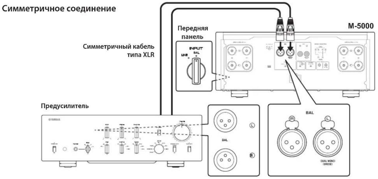
CmmMeTpnuHoe coeDnHeHne
CHMMETPHHoe COEINHHNE OTJINHPO pIeAer Ipo6JIemy BHEIHHEO IIIyMa.ДIa CHMMETPnHOro COEINHHeHHN HCIOJIb3yIte Ka6JIb co IITEKePHbIM pa3BeMaMn XLR.IpH IOIKIIIOChHH Ka6JIa O6JIaTCJIbHO COBMEcHTHe KOITAKTbI pa3BeMa c OTBepCTHMn IHe3Ja, a 3ATCM BCTaBBcpe Pa3BeB M BRc3do JIO IIcJIuKa. YTO6bI OTCOEINHHb Ka6JIb, HAKMITE N yIEpKJBBaIte pbIaKOK Ha IHC3Ic BAL IN BBtAnIHTe IITEKePbHb pa3BeM XLR n3 IHe3Ja.
IpiH co3aHHc CHMMETPHUIORO coeHNHeHHO 6OBaTeJIbIO CO6JIHOaJIte IpaBnJIbHyTO IOJIaRpHOCTb. DIA NaCTPOJKN IOJIaRPhOCTH HcNOJIb3yIte CeJIeKTop PHASE Ha 3aJHei IIaHEJI.

EcJIN ceJIeKTop PHASE ycTaHOBJIeH B IIOJOKeHHe NORMAL, KOHTaKT #2 cTAHOBHcI KOHTaKTOM HOT.
EcJIn ceJIeKTop PHASE ycTaHOBJIeB HIOJOKeIIHe INVERTED, KOHTaKT #3 cTaHOBITcKoHTaKTOM HOT.
PpmeaHne
Bb6epTe 3NaueHne NORMAL (KoHTaKT #2 ABnEeTc KoHTaKTOM HOT) nI pyonrpblBaTeN nn npeducnteYamaHa.
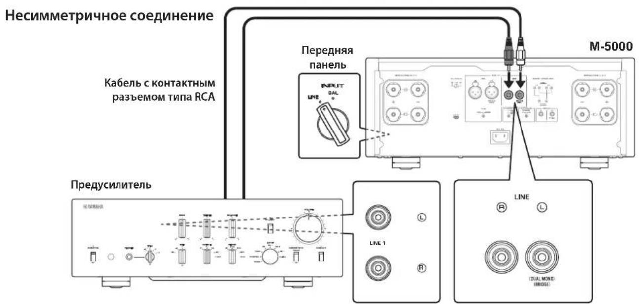
HecmmMeTpnuHoe coeHNHeHne
HHeHHMMeTpHOro CoeHHcHn HcNoIb3yHt cKa6eHH C KOHTaKTHbIMn pa3bEmAMn TnHa RCA. OH He HepeJaOT f3OByIO HHOpMaHIO.
Подключения
B daHHOM pa3JeIe onncbIbAeTc IpoueIpya IIOKJIIOUeHnnaIapapaT K IIpeDyucNJInTeJIIO H KOJIOHKam.

BHUMAHNE
OTKIOHHTe NITaHHe BCEx KOMNoHEtOB NepeD BbINOnHeHEm NOkIIOueHn.
YBEDOMJIENHE
Ipeep noKIOueHEm BHeUHX KOMHOHeTOB 03HaKoMbTeCb C pyKOBOCTBaMn NO 3TMM KOMHOHeHTa M nCleNyTe Yka3aHHbIM B Hnx IHCTpyKzmaM. B npOTNBHom cnyae MOKeT BO3HKnHyTB HeCNpabHObct aannapata NIN BHEUHX KOMHOHeTob.
IIOKIOHHTe IpeDyCHINTEb K BXOHNbIM THe3dAm aIInapaTa. IJIaAHHOIOKIOHcHnHIOJIb3yTe CHMMETpHbIE Ka6cJIN THII XLR HIN HecHMMeTpPHbIE Ka6cJIN THII RCA.
YBEDOMJIENHE
YpOBeHb rPOMKoCTn annapata fNkCnpOBaH. He
NoIKnIOuayTe KOMNOHEHT, KOToBb He NMeET fYHKcnn
perynipOBKn rPOMKoCTn, K BXOHNbIM rHe3dAm annapaTa.
B npOTUBHom cnyae BO3MOXHO BOCpON3BeDeHne
rPOMKoro 3Byka, YTO MoKeT npNBecT N HeNCnPabHOCTn
annapata nIN NOBpeKdeHIO KOLOHOK.
PpMueaHne
Ecn npeducntenb noepknaeT cmmMeTpHoe HecmmMeTpHoe coeHHeHne,ncnoB3yTe CmmMeTpHoe coeHHeHne.
He nCnoIb3yIte CmmMeTpUHbIe HecmMMeTpUHbIE CoeINHeHn MExNy DByM KOMNoHEHTAMN OHOBpeMeHHo. 3To MOKeT CΦOpMnPOBaTb KOHTyp 3a3EmJIeHn, KOtOpBI CO3Jaet CTaTNueCKNe NOMEXn I Wym.
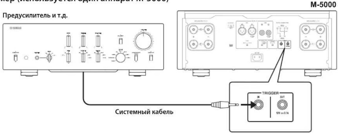
TpnrrepHbIe coeINHeHnA
Bb MoKTe ynpabTb BkIOueHEm H BkIOueHEm IHTaHH aIInapaTa cHHxpoHHc IIIKIOueHHbIM KOMIOHeHTOM
Yamaha, TakHM KaK IpCycnIHTcJIb II IN AV-pechBcp.
HIOJB3yIe IpiJIaFembI CNCTEmhBkKa6JIb JIOJIKIOUeHHN,IOKA3aHHbIX Ha CXEMEHKe.
Ppimep (ncnojb3yeTc8 oDn annapaT M-5000)
Ppimep (ncnoj3yioTcya annapata M-5000)
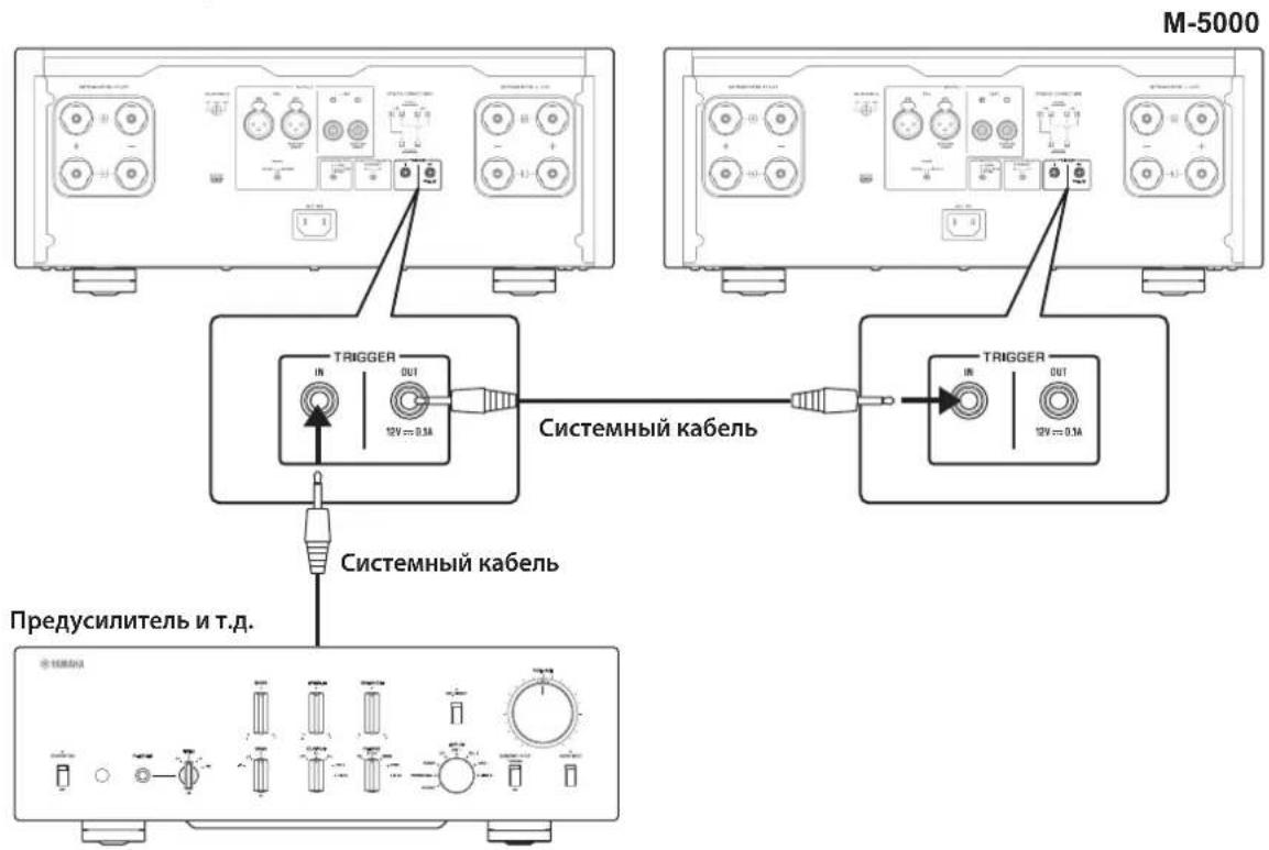
YTo6bIynpaBnTb aHnapaTOM B KOHfHypaHH TPHTcPHO CocINHcHn, yCTaHOBTc IcpeKIOuATc. STANDBY/ON/OFF (PiTaHne) B HIOJIOKeHne STANDBY/ON.
Pn BKIOUeHHIHTAHN IIOKJIIOUeHHORO KOMIOHENTa IHTaHNC aIIIAPAta TaKKe BKIOUaCTc. Pn BbIKIOUChHH IHTaHNN IOKJIIOUeHHORO KOMIOHENTaJaHHbI aIIHapAT IpcxOJNTBpcHM OKHJaHH.
PpmeaHne
Korda nepekniouateIb nItaHnHa annapaTe yctaHOBneB noJoxeHne OFF, nItaHne annapaTe He 6ydet BkIouaTbcR.
OchOBhble NOdkJIoueHnKoJohOK
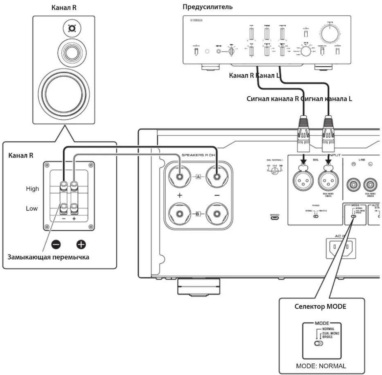
1 BbIKIIOHTe NITaHne annapata N BCex NOdkIIOUeHHbIX KOMNOHETOB.
2 UcTaHOBnTe ceNeKToP MODE Ha 3aDHe nHaHEn B noJoxHeNe NORMAL.
3 YctaHOBnTe celenkTop SPEAKERS Ha nepeHHe naneB noLoXeHne A, B nnA+B BI-WIRING.
Ha cxeme ceJIeKTop yCTaHOBJIEH B IIOJOKeHne A.
4 IopKnIOUHTe yCnIInTeIb MoHocTn K TePMHaJAM "+"" Ha KOJOhKax.

BHIMAHHE
O6raTeBHO NcNoB3yNe KOLOHKn, KOTOpbIe HMeHOT COpoTnBHeHne, NOKa3aHHoe B Ta6nue HnKe.
ConpoTnBHeHne KOHOK
TOnuHa JaPa TepMnHa:5,0 MM
2 3akpynte roNoBky.
YeTbipexnpoBODhble NOdklouyeHnA
IJIyHETbIPeXIIPOBOHOIOIOJIIOUOHeHHKOJOHOK pa3cJIHTe Ka6cHN, HIOIOJIb3yEmbc IINIOJIOUOHeHH IHPB0Ja cpeIHn H BbICOKHX YactOT (BbICOKOaCTOTHOI INHAMKa) H IIpHB0Ja HN3KHX YactOT (HN3KOaCTOTHOI INHAMKa) Ha KaXIOJ KOIOHKe C YETbIPeXIIPOBOIDBM IOIKIOUChEM K yCNITeIIO. IIPOKJIaIBaHHe OTJeIbIbIX Ka6JIeH OT yCNJIHTeIMoKET yCNJIHTb OΦΦcKTHC HAYTBA C KOHTpyBa BbICOKOaCTOTHOI INHAMKa HApy3Kn O6paTHo NHPkyJINH 3DC (OJIckTpOJBHKUeH cnJIb), rCEHpPyemOH 3ByKOBoI KAtyIKoH HN3KoAaCTOTHOI INHAMKa, B pe3yJIbTaTe CHNkaeTc HINTeppeHIIH MeKJy DHaIIa3OHaMH BbICOKHX HN3KHX YACTOT H NOBbIIaETcRA KaueCTBO 3ByKa.
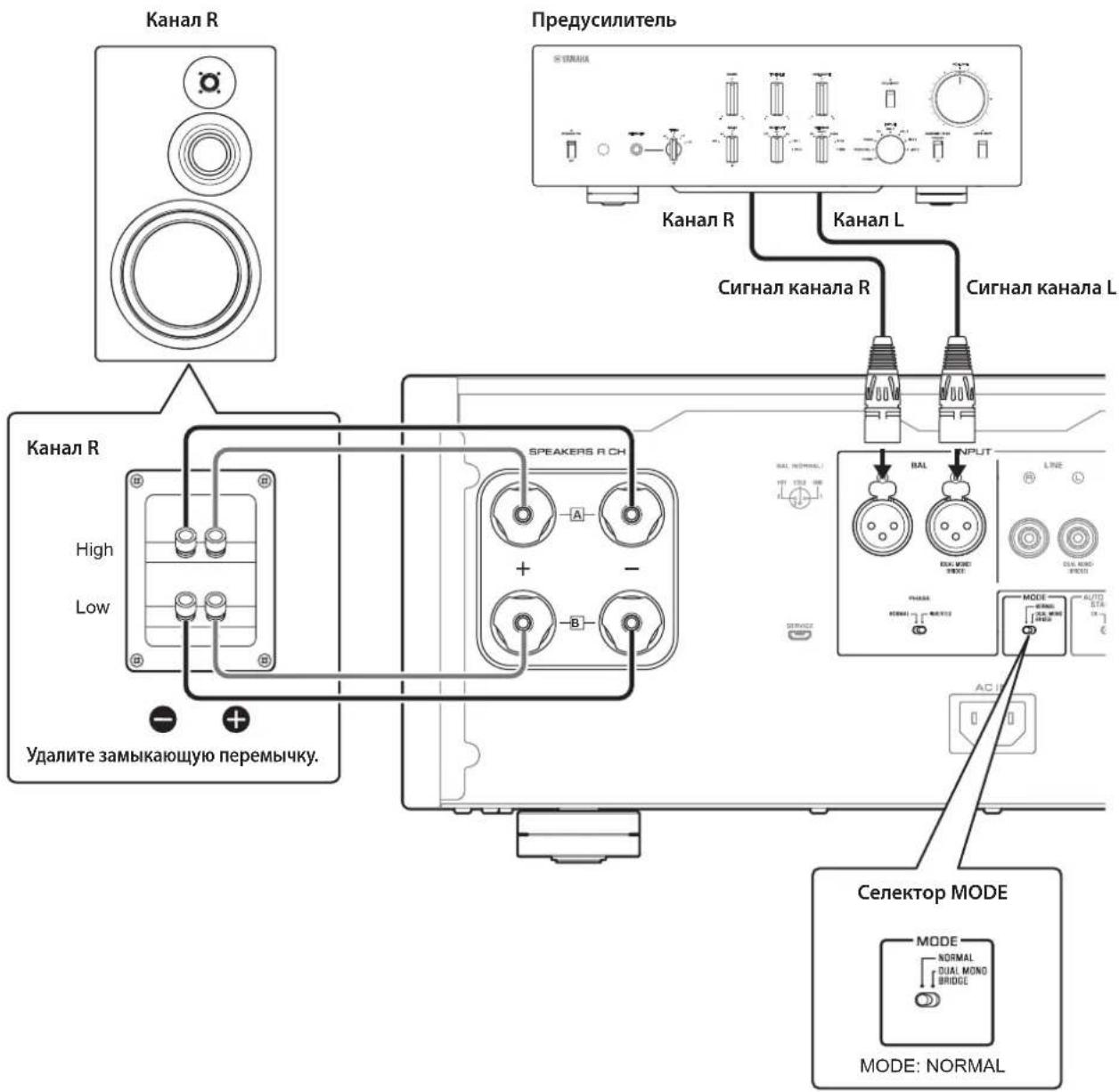
HeoXIOHMO HcIOJIb3OBAITb KOJIOHKN, KOTOpBIE HMeOT IBaKOMIIeKTA TepMHHaIIOB (BceFoYeTbIpe), YTO HO3BOJIeT pa3JeIHTb KaKJyIO KOJIOHky Ha IBe CeKIIHN (HnHaIa3OHI Hn3KHx H cpcIHHX/BlICOKHX YaCTOT).
1 BbIKIOUHTe NHTaHne annapata n BCex NODKIIOUeHHbIX KOMNOHETOB.
2 ydaJInte 3aMbIkaIOuIne nepeMbIcKn IIN MOCTIKN Ha KOJOhKaX.
KpoccoBepb LPF (HJIbTp H3KHX qactOT) HPF (HJIbTp BbICOKHX qactOT) 6yIyT pa3JcJcHbI.
3 POnKnIOuHTe yCUNITeIb MOUHOCTN K KOJOhKaM.
IIOKIOHKn KaKaIOrO KaHaJa IIOJKIIHOHTc Ka6CINOT TepMHIAIOB DnAIIa3OHa CpeDIIHX/BbICOKHXaCTOT Ha KOJIOHKe K rHe3dAm COOTBeTCTBYIOIEKAKaHaJa SPEAKERS A Ha ycHJIInTeJe, a ot TepMHIAIOB DnAIIa3OHa Hn3KHX YactOT HaKOJOHKe K rHe3dAm COOTBeTCTBYIOIEKAKaHaJa SPEAKERS B Ha ycHJIInTeJe COOTBeTCTBeHNO.
4 YctaHOBnte celenkTop MODE Ha 3aHne naHeIN B NOJKeHne NORMAL.
5 YctaHOBnte ceneKTop SPEAKERS Ha nepeHne naneB noLoXeHne A+B BI-WIRING.
BHIMAHHE
063aTeIbHO NcONb3yIe KOIOHKn, KOTOpBie IMeHOT conpoTnBHeHne, nOKa3AHoe B Ta6Nue HnKe.
ConpoTnBHeHne KOHOK
*3a ncklnoueHnem MoJene JnCAJA KaHaBbI

BHUMAHNE
IpepeBkIIOueHEm nITaHnHa NCXODHom KOMnoHeHTe CHaYana yMeHbWITE yPOBeHb rPOMKoCTn Ha DaHHOM KOMNOHEHTe.
Moctoboe coeHneHne
B KOHpyaHH MocTOBORO COeHNHeHH B KaueeCTBE MOHOOHueckoro yCHINTEJ HcIOJIb3yETcM-5000. JIa co3aHH CTepcoehCTmbl Hc6xoHMo IBa anIapata M-5000.
Ha KaKaJOM ycHJIHTeJe NOJKIOHOHTe TepMHaJI “+” SPEAKERS L CH K TepMHaJIy “-” SPEAKERS R CH. JIaIaHHoT OIOKIOUHeH NcIOJIb3yIte Ka6JIb H3 TOrO JKe MaTePHaJIa, YTO H Ka6CJIH KOIOHOK, IINHOH 1,0 M HIn McHeE H IOIIpeCHyBM cceHHeM 1,0 MM² HIn BoJee. He CkpyHBAITE Ka6JIb.
IIOKIIIOHHTE HCTOHHK BXOIIHO CRHnHa KaBXOIIbIM rHe3aam KaHaJaL Ha o6oHx aannapatax M-5000.
YBEDOMJIENHE
IocKobkyucJIeHHeBdaHHoN KOHfIgpaunn
6yTe yDBoEHO,HaCTpoTe yPOBeHb rPOMKOCTn COOTBeTCTByUOIM O6pa3OM Ha NODKIOUeHHom
npEyCunNTene.EcnnncNoJb3yeTc npEyCunNTenb
Yamaha cceKeTOpom GAIN,HaCTpoTe yPOBeHb rPOMKOTn C NOMOsbDaHHOrO ceKeTOpa,YTO NO3BOJNT
NCNoJIb3OBaTb JIeMeHTbI yPpAbNEHn rPOMKOCtBu Ho
dpyrNX KOMNoHEtAX B O6bUHOM nopAKe.
1 BbIKIIOUHTe NITaHHe annapata n BCex NOdkJIIOUeHHbIX KOMNOHEHTOB.
2 YctaHOBnte ceneKTop MODE Ha 3aHne NaHeIN B NoJoxEne DUAL MONO/ BRIDGE.
3 YctaHOBnte ceIeKTop SPEAKERS Ha nepeHne nane B noLoXeHne A, B nn A+B BI-WIRING.
Ha cxeme ceJIeKTop yCTaHOBJIeB IIIOJOKeHHe A.
Ha KaJdom ycuiIte neoKIOuHTe TepMnHaJ " ^+ " SPEAKERS L CH K TepMnHaNy "-" SPEAKERS R CH.
5 Пдклочи Термун"+" SPEAKERS R CH K Tepmuna"+" Ha KOLOHKe, a Tepmuna "-" SPEAKERS L CH K Tepmuna"-" Ha KOLOHKe.
BHIMAHHE
063aTeIbHo NcONb3yIe KOIOHKn, KOTOpBie HMeHOT cnpoTnBHeHne, noka3aHHoe B Ta6nue HnKe.
COnpoTnBHeHne KonoHok
MoHOoHnueckn,8OM 400BT
HnHaMnuecka MouHocTb
8OM 125BT+125BT
6OM 170BT+170BT
4OM 250BT+250BT
2OM 500BT+500BT
MaKcMaIbHoe BbIXOHaJ MoIHOCTb
(1 kΓu, 0,7% KHN)
[MoJIeJIH JIA CoeJHHHeHOro KopoJIeBCTBa H cTpaH EBpOJIbI]
4OM 220BT+220BT
BbIXoHnA MoHocTb IEC (1 KfU, 0.02% KHU)
[MoJcH JIcCuaHHeHHoKopoJIeBCTBa H ctpaH EbpHbI]
8OM 125BT+125BT
MaKcMaJIbHoe 3ΦΦeKTbHbAaBbIXOHaMaMoUHOCTb (JEITA,1KΓu,10%KHU)
[MoJIINIINKITa,KopcH,CocHHHnHO
KopoJIeBcTbA,A3HH,IIeHTpaJIbHOH HIOXHOI
AmePNKn TaBbAn]
8OM 135BT+135BT
4OM 270BT+270BT
Duaana3OH qACTOT NOnHOI MOUHOCTH
(MAIN L/R, 0.1% KHN, 45 Bt)
8OM .0T 10IIO50KII
Ko3ΦnUneHT demnΦnpOBaHn(1Kr)
8OM 300
BxOHaHyBCTBtEnbHOcB/BxOdHoe cOpTnBneHHe
(1 kF, 100 BT/8 OM)
BAL...2,0B,cpeIHeKBAipaTHHoe 3NaueHHe/47 KOM
LINE.1,0B,cpeHckBaIpaTHHoc 3NaCHHe/47 KOM
MaKcMaJIbHoe HapRJaKeHne BXoDHoro CnHaJia
(1 kΓι, 0,5% KΗΝ)
BAL. 2,20 cpeHHeKBaIpaTHuHoc 3HaueHHe
LINE. 1,10 cpeHneKbIpaTHuHoe 3HaueHHe
YactothaXapaKTepeNCTnka
OT5ΓIIO100KΓI. +0/-3B
OT20TIO20Ku. +0/-0,3B
Ko3ΦHnueHT HeHHeHbIX NcKaKeHn C yETOM wma (ot 20 T do 20 K
2-kaHaJIbHbI,
LINE IO SPEAKERS, 50 BT/8 OM .035%
2-kaHaJIbHbI,
BAL IO SPEAKERS, 50 Br/8 OM .035%
MoHoofoHHueckn,
LINE IO SPEAKERS, 200 BT/8 OM. .05%
MoHooHnueckn,
BAL IO SPEAKERS, 200 Br/8 OM. .05%
Pa3deneHne kaHana (BxO1, 0 kOM, 3amKHytb)
1KΓ/10KΓ. 90B/≥70dB
Coothouenue cnHn/whm (CeTb IHF-A,BXo1,0KOM
3aKopoueHbI, KOHTpOJIbHbI ypoBeH 200 Bt/4 Om)
110AB
OcTaToUhBm Wm (cTeb IHF-A)
BAL. 40 MKB, cpeHHeKbAipaTHHoc 3HaueHHc
LINE. 50 kB, cpeHneKBaIpaTHHoe 3NaueHHe
ToHocTb n3MepeHnA
Klacc 2,5
IcToHnK nTaHn
[MoJeIINIJIaCIIAHKaHaIbI] 120B IpcpeMeHHoro ToKa,60T
[MoJIbIJIaKHTa] 220BncpcmchHoro Toka,50I
[MoJIbJIOH Kopen] 220B IepemehHO ToKa,60I
[MoJIbIABcIpaIIH] 240B IepemehIO TOka,50T
[MoJIeJIHIII CoeINHeHHOrO KopoJIeBCTBa H cTpaH EbpHbI] .230 B IIepeMeHHoro Toka, 50 T
[MoJIbIJIyA3HH] 220-240BIIpeMeHHOToKa,50T/60T
[MoJeJINIJIIeHTpaJIbHOH IN IOKHOH AmePHKN H TaBHa] .110 B NepcMCHHOro ToKa, 60 Tn
3hepronotpe6neHne
400B
3Hepronotpe6enneB pexnme oxndaHna
BbIKJIOHHeOeCOCToHHne 0,1BT
PekHM OKHdHn .0,2Bt
MaKcImaIbHoe3HeprnoTpe6JIeHne
(1 KΓU, 4 OM 10% KHN)
[MoicnIJIuIcHtpaJIbHOHIOJHOAmcpHN H TaBHa] .800 Br
Pa3Mepbl (U×B×Γ)
435× 180× 464MM
Bec
26.9K
*B coepkaHHI daHHoro pyKOBOCTBA IIpHBeIeHb IocJIcIHNC Ha MOMCHT IIy6JIHKaIIHN TCXHHueCKHC xapaKTEPnCTKN. JIINIOJYueHn IOCJIeIHeN BepCNH pyKOBOCTBA IocCtHTc Be6-caIT KOpPiopaHn YamaHa n 3aIpy3HTe faiI c pyKOBOCTBOM.
БлOK-cхema

XapakTepnctnKn aydnocnHaJa
Ko3ΦnCHeNTH HeINHeiHbIX NCKaXeHn (8OM)
Ko3ΦnCHeN T HeiHHeiHbIX nCKaXeHn (4 Om)
Ko3ΦnueHT HeHHeHbIX nckaeHm (MOHOHNueckn, 8 OM)
YacToTHaXapaKTePnCTnKa
Bo3MOxHbIe HeIcIpaBHOCTN I cNoCo6bIXyCTpaHeHnY
EcnIaHHbI aIIIapat pa6oTaT HeIpaBnIbHo, cm. Ta6IuH y Hnke. Ecln HencIpaBHOctb He yKa3Ha B Ta6JIuIe IIN Bt He cMOJIY ycTaHHTb ee, cJeIyra HnCTpyKIIHm Ta6JIuIbI, OTKIOUHTe aIIIapAT, OTCoeIHInTe cHIOBOI Ka6JIb H 6paHTccB K 6JIHkaIIMeMy aBTOpH3OBAHHOMy IIIEpy IIN B CcpBnCbI ιeHTp YamaHa.
| Немправноctrь Кличесу Способ устра themselves | См.стр. | ||
| Питанные НВлючесry. | Слобов Кабелы не поочны. К разьему AC IN на за干嘛е паслы ял не вдюочи в разетку переменогу тока. | ПлобочITE симobой Кабел соштвettingуших м образим. | 248 |
| Быla akтувирoveна схема Зашаты ИЗ-3a корOTКОТ Замыкannahи и.T.d. | Убенистсь, чTo повoda колонok He сорпекасотя дуг с дугом по по Замкинты корOTКС зад徳 по по Данноу орлара, и 3atem сюва ВлючITE пita themselves apnapata. | 240 | |
| Данный орларat поочгся СлльнOMу ЗлковсяckOMу напраженью OT Вс��них Источников (напrimер, молné, плсьhoe сатческoe элковсяпессы). | БыковочITE apnapat, отсанинite симobой Кабел ot розетки переменогу тока, поождentre Okono 30 секунд, a заlem сюва поklючITE appapat. | 248 | |
| Мiraет Иndидахл STANDBY/ON на п的对象л. | Быla akтувирoveна схема Зашаты ИЗ-3a корOTКОТ Замыкannahи и.T.d. | Убенистсь, чTo повoda колонok He сорпекасотя дуг с дугом по по Замкинты корOTKС зад徳 по по Данноу apnapata, и 3atem сюва ВлючITE пita themselves apnapata. | 240 |
| Иmeetся пооблеса с ВнUTревими схема Дадноу annapata. | Отсанинite симobой Кабел OT розетки переменогу тока и образимость к ближайшему авторизованomy дileperу по В сервись сcentр Yamaha. | 248 | |
| HéncnPabNocThb Pnvn | HnHa CnOco6 yctpaHene | Cm. ctrp. | |
| Annapat BkIouche, Ho 3Byk He cnblshen. | Быla akTbVipObaHa cXema 3aunlby I3-3a KOpOTko 3aMbKaHnry I T.d. | Y6eJntecb,чTo npOboDa kOLIOHok He cOnpNKacAOTcA dpyrC dpyrOM nLIyHe 3aMKHytbl KOpOTko C 3aDnei naHelbu DaHNO rappata, n 3aTeM cHOBa BkIouchte pHTaHne aPapata. | 240 |
| СeNeKTop SPEAKERS uCTaHoblen B noLoxehne OFF. | UCTaHOBIne cSeKTop SPEAKERS B COOTBETCTBvUoOee noLoxehne. | 230 | |
| КабелkoJIOHOK noDkluoyehbI HeNPrabinlbNo. | Y6eJntecb B TOM,чTo Ka6eNik KOLOHOK noDkluoyehbI npabinlbNo. | 240 | |
| ПоLoXeHne cSeKTop lPINT H e COOTBETCTBvyET noDkluoyehHomU ySTOCHNY BxOJHO rCINHana. | ВьбepIne coOTBETCTBvUoOii nIcTOHnik BXODHORO CINHana C nOMOUsbIoo ceLKeTopa INPUT Ha nepeDnei naHeli. | 236 | |
| 3Byk HeoXuDanHo OTKIIouaetc. | Быla akTbVipObaHa cXema 3aunlby I3-3a KOpOTko 3aMbKaHnry I T.d. | Y6eJntecb,чTo npOboDa kOLIOHok He cOnpNKacAOTcA dpyrC dpyrOM nLIyHe 3aMKHytbl KOpOTko C 3aNDei naHelbu DaHNO rappata, n 3aTeM cHOBa BkIouchte pHTaHne aPapata. | 240 |
| КолONKIIpoKUoyehbI HeNPrabinlbNo. | Y6eJntecb B TOM,чTo KOLOHKn IIpoKJIoueHbI npabinlbNo. Ecnil HeNCnPabNocTb COxpaHЯETcR, Ka6eNIMoγt 6blT deΦeKTbIMi. | 240 | |
| HedocTATOK Hn3Knx Chactot nLIy OTCytCTBme npoctpanCTBENHOro 6Obemar 3Byka. | П探测DA+И-Ha YCSIITeile nLIy KOLOHak noDkluoyehbI C HeNPrabinlbNoI noIparPHocTbU. | П探测DA探测DA KOLOHOK C npabinlbNoI noIparPHocTbU + I-. | 239 |
| Cblshen rydaun 3Byk. | СиMMeTpniuHbIe n HeSiMMeTpniuHbIe Ka6eNII nCnOJIb3yIOTcOndOBpeMeHHO MekdY DvBMy KOMIoHENTam. | He nCnOJIb3yIe tsimMeTpriuHbIe n HeSiMMeTpniuHbIe Ka6eNII oNDOBpeMeHHO MekdY DvBMy KOMIoHENTam. 3To MOKet cfOpMiroBaTb KOHTyp 3aZeMLeHHa, KOTopBiy Co3daet CTaTIueckne nomexn I Shym. | 236 |
yka3aTeJIb
B
BkJIIOUChHc IHTaHH 230
BxoJHoc rHc3IO BAL 236
BxoJHoc rHe3IO LINE 236
F
Tne3no SERVICE 233
THe3IO TRIGGER 237
M
HHKATop STANDBY/ON/OFF 230
HdHKaTop HHTaHH 230
K
Ka6eJIb c BHIKOo6pa3HbIM HAKOHeHHKOM 241
M
MoCTOBoe coeINHeHne 246
H
HeCMMeTpHoe coeHHHeHHe 234
HoxkN 233
#
IpekeJIOHoyaTeJB AUTO POWER STANDBY...233
IpcckJIOUqatcJIb STANDBY/ON/OFF 230
IIpekeJIOUaTeJIb IIHTaHHN 230
IIKJIIOUeHHe Ka6JIeIe KOJIOHOK 240
IIoIKJIIOueHHe KOJOHOK 238
IIIOJIIOUeHHe IpeIyCnHTeJI 236
PIOKJIIOUeHHe cIbMyyChJIHTeJIaMn 244
C
CeJIeKTop INPUT 236
CenekTop METER 231
CeJIeKrOp MODE 233
Ciekekrop PHASE 234
CcJekTrop SPEAKERS 230
ChIOBOI Ka6JIb 248
CMMMeTpHnOe BxOJHoe THe3I0 236
CMMMeTpHnOe coeHHHeHHe 234
T
TprrepHoe coeHHHeHne 237
4
UcTbIpcxIIpOBoIHOCIOIKIOueHHe 242
Yamaha Global Site
https://www.yamaha.com/
Yamaha Downloads
https://download.yamaha.com/