
MXA5200 - Home cinema amp YAMAHA - Free user manual and instructions
Find the device manual for free MXA5200 YAMAHA in PDF.
| Product Type | 11-channel home cinema amplifier |
| Brand | YAMAHA |
| Model | MXA5200 |
| Dimensions (W x H x D) | 435 x 211 x 464 mm (including feet and protrusions) |
| Weight | 26.4 kg |
| Power Supply | AC 120 V, 60 Hz (US model); other versions available |
| Power Consumption | 650 W (max 1500 W all channels driven); standby 0.1 W |
| Number of Channels | 11 channels |
| Rated Output Power | 150 W per channel (8 Ω, 20 Hz-20 kHz, THD 0.05%) |
| Compatible Speaker Impedance | 6 Ω or higher (8 Ω for CH.3 A+B and bridging) |
| Audio Inputs | 11× unbalanced RCA, 11× balanced XLR |
| Speaker Outputs | 13 terminals: CH.1, CH.2 L/R, CH.3 A/B L/R, CH.4 L/R, CH.5 L/R, CH.6 L/R |
| Other Connectors | TRIGGER IN/OUT/THROUGH OUT (3.5 mm mini-jack) |
| Main Functions | Channel selection, bi-amplification, bridging (BRIDGE), multi-speaker (3 speakers per channel), SPEAKERS A/B switching, Trigger function, auto standby, indicator brightness adjustment |
| Safety | Protection circuit (overheating, short circuit), automatic shutdown in case of anomaly |
| Maintenance and Cleaning | Disconnect the device before cleaning; use a soft dry cloth. Do not use chemical products. |
| Supplied Accessories | Power cable, system control cable, instruction manual |
| Repairability | Have any repairs carried out by a qualified Yamaha technician. Do not attempt to disassemble the device. |
Frequently Asked Questions - MXA5200 YAMAHA
User questions about MXA5200 YAMAHA
0 question about this device. Answer the ones you know or ask your own.
Ask a new question about this device
Download the instructions for your Home cinema amp in PDF format for free! Find your manual MXA5200 - YAMAHA and take your electronic device back in hand. On this page are published all the documents necessary for the use of your device. MXA5200 by YAMAHA.
USER MANUAL MXA5200 YAMAHA
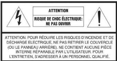
IMPORTANT SAFETY INSTRUCTIONS
The above warning is located on the rear of the unit.
• Explanation of Graphical Symbols

The lightning flash with arrowhead symbol, within an equilateral triangle, is intended to alert you to the presence of uninsulated "dangerous voltage" within the product's enclosure that may be of sufficient magnitude to constitute a risk of electric shock to persons.

The exclamation point within an equilateral triangle is intended to alert you to the presence of important operating and maintenance (servicing) instructions in the literature accompanying the appliance.
I Read these instructions.
2 Keep these instructions.
3 Heed all warnings.
4 Follow all instructions.
5 Do not use this apparatus near water.
6 Clean only with dry cloth.
7 Do not block any ventilation openings. Install in accordance with the manufacturer's instructions.
8 Do not install near any heat sources such as radiators, heat registers, stoves, or other apparatus (including amplifiers) that produce heat.
9 Do not defeat the safety purpose of the polarized or grounding-type plug. A polarized plug has two blades with one wider than the other. A grounding type plug has two blades and a third grounding prong. The wide blade or the third prong are provided for your safety. If the provided plug does not fit into your outlet, consult an electrician for replacement of the obsolete outlet.
10 Protect the power cord from being walked on or pinched particularly at plugs, convenience receptacles, and the point where they exit from the apparatus.
11 Only use attachments/accessories specified by the manufacturer.
12 Use only with the cart, stand, tripod, bracket, or table specified by the manufacturer, or sold with the apparatus. When a cart is used, use caution when moving the cart/apparatus combination to avoid injury from tip-over.
13 Unplug this apparatus during lightning storms or when unused for long periods of time.
14 Refer all servicing to qualified service personnel. Servicing is required when the apparatus has been damaged in any way, such as power-supply cord or plug is damaged, liquid has been spilled or objects have fallen into the apparatus, the apparatus has been exposed to rain or moisture, does not operate normally, or has been dropped.
IMPORTANT
Please record the serial number of this unit in the space below.
MODEL:
Serial No.:
The serial number is located on the rear of the unit. Retain this booklet in a safe place for future reference.

FCC INFORMATION (USA)
I IMPORTANT NOTICE: DO NOT MODIFY THIS UNIT!
This product, when installed as indicated in the instructions contained in this manual, meets FCC requirements. Modifications not expressly approved by Yamaha may void your authority, granted by the FCC, to use the product.
2 IMPORTANT: When connecting this product to accessories and/or another product use only high quality shielded cables. Cable/s supplied with this product MUST be used. Follow all installation instructions. Failure to follow instructions could void your FCC authorization to use this product in the USA.
3 NOTE: This product has been tested and found to comply with the requirements listed in FCC Regulations, Part 15 for Class "B" digital devices. Compliance with these requirements provides a reasonable level of assurance that your use of this product in a residential environment will not result in harmful interference with other electronic devices.
This equipment generates uses radio frequencies and, if not installed and used according to the instructions found in the users manual, may cause interference harmful to the operation of other electronic devices.
Compliance with FCC regulations does not guarantee that interference will not occur in all installations. If this product is found to be the source of interference, which can be determined by turning the unit "OFI" and "ON", please try to eliminate the problem by using one of the following measures:
Relocate either this product or the device that is being affected by the interference.
Utilize power outlets that are on different branch (circuit breaker or fuse) circuits or install AC line filter/s.
In the case of radio or TV interference, relocate/reorient the antenna. If the antenna lead-in is 300 ohm ribbon lead, change the lead-in to coaxial type cable.
If these corrective measures do not produce satisfactory results, please contact the local retailer authorized to distribute this type of product. If you can not locate the appropriate retailer, please contact Yamaha Corporation of America A/V Division, 6600 Orangethorpe Avenue, Buena Park, CA 90620, USA.
The above statements apply ONLY to those products distributed by Yamaha Corporation of America or its subsidiaries.
* This applies only to products distributed by YAMAHA CORPORATION OF AMERICA.
COMPLIANCE INFORMATION STATEMENT
(Supplier's declaration of conformity procedure)
Responsible Party: Yamaha Corporation of America
Address: 6600 Orangethorpe Avenue, Buena Park, CA 90620
Telephone: 714-522-9011
Type of Equipment: Power Amplifier
Model Name: MX-A5200
This device complies with Part 15 of FCC Rules. Operation is subject to the following two conditions:
(1) this device may not cause harmful interference, and
(2) this device must accept any interference received including interference that may cause undesired operation.
The above statements apply ONLY to those products distributed by Yamaha Corporation of America or its subsidiaries.
CAN ICES-3(B)/NMB-3(B)
PRECAUTIONS
PLEASE READ CAREFULLY BEFORE USE. BE SURE TO FOLLOW THESE INSTRUCTIONS.
The precautions listed below are to prevent risk of harm to the user and others, as well as to prevent property damage, and to help the user use this unit properly and safely. Be sure to follow these instructions.
After reading this manual, be sure to keep it in a safe place where it can be referenced at any time.
- Be sure to request inspections or repairs from the dealer where you purchased the unit or from qualified Yamaha service personnel.
- Yamaha cannot be held responsible for injury to you or damage of the products caused by improper use or modifications to the unit, or data that is lost or destroyed.
- This product is for ordinary homes. Do not use for applications requiring high reliability, such as managing lives, health care or high-value assets.

WARNING
This content indicates "risk of serious injury or death."
Power supply/power cord
- Do not do anything that could damage the power cord.
- Do not place it near a heater.
- Do not bend it excessively or alter it.
- Do not scratch it.
- Do not place it under a heavy object.
Using the power cord/adaptor with the core of the cord exposed could cause electric shocks or a fire.
- Do not touch the power plug or cord if there is a chance of lightning. Failure to observe this may cause electric shocks.
- Use this unit with the power supply voltage printed on it. Failure to connect to an appropriate AC outlet may cause a fire, electric shocks, or malfunctions.
- Be sure to use the power cord. Also, do not use the supplied power cord for other units. Failure to observe the above may cause a fire, burns, or malfunctions.
- Check the electric plug periodically and remove any dirt or dust which may have accumulated on it. Failure to observe this may cause a fire or electric shocks.
- When setting up the unit, make sure that the AC outlet you are using is easily accessible. If some trouble or malfunction occurs, immediately turn off the power switch and disconnect the plug from the AC outlet. Even when the power switch is turned off, as long as the power cord is not unplugged from the wall AC outlet, the unit will not be disconnected from the power source.
- If you hear thunder or suspect approaching lightning, quickly turn off the power switch and pull the power plug from the AC outlet. Failure to observe this may cause a fire or malfunctions.
- If not using the unit for long periods of time, be sure to pull the power plug from the AC outlet. Failure to observe this may cause a fire or malfunctions.
Do not disassemble
- Do not disassemble or modify this unit. Failure to observe this may cause a fire, electric shocks, injury, or malfunctions. If you notice any irregularities, be sure to request an inspection or repair from the dealer where you purchased the unit or from qualified Yamaha service personnel.
Water warning
- Do not expose the unit to rain, use it near water or in damp or wet conditions, or place on it any containers (such as vases, bottles or glasses) containing liquids which might spill into any openings or places where water may drop. A liquid such as water getting into the unit may cause a fire, electric shocks, or malfunctions. If any liquid such as water seeps into the device, turn off the power immediately and unplug the power cord from the AC outlet. Then, request an inspection from the dealer where you purchased the unit or from qualified Yamaha service personnel.
- Never insert or remove an electric plug with wet hands. Do not handle this unit with wet hands. Failure to observe this may cause electric shocks or malfunctions.
Fire warning
- Do not place any burning items or open flames near the unit, since they may cause a fire.
Maintenance and care
- Do not use aerosols or spray-type chemicals that contain combustible gas for cleaning or lubrication. The combustible gas will remain inside the unit, which may cause explosion or fire.
If you notice any abnormality
- If any of the following abnormalities occur, immediately turn off the power and disconnect the power plug. If any of the following abnormalities occur, immediately turn off any amplifiers and receivers.
- The power cord/plug is damaged.
- An unusual smell or smoke is emitted from the unit.
- Foreign material gets into the interior of the unit.
- There is a loss of sound during use.
- There is a crack or damage in the unit.
Continued use could cause electric shocks, a fire, or malfunctions. Immediately request an inspection or repair from the dealer where you purchased the unit or from qualified Yamaha service personnel.
- Be careful not to drop or apply strong impact to this unit. If you suspect the unit may have been damaged due to dropping or impact, immediately turn off the power and pull the power plug from the AC outlet. Failure to observe this may cause electric shocks, a fire, or malfunctions. Immediately request an inspection from the dealer where you purchased the unit or from qualified Yamaha service personnel.

CAUTION
This content indicates "risk of injury."
Power supply/power cord
- Do not use an AC outlet where the power plug fits loosely when inserted. Failure to observe this may cause a fire, electric shocks, or burns.
- When removing the electric plug from the unit or an AC outlet, always hold the plug itself and not the cord. Pulling by the cord can damage it and cause electric shocks or a fire.
- Insert the power plug firmly all the way into the AC outlet. Using the unit when it is not plugged in sufficiently can cause dust to accumulate on the plug, causing a fire or burns.
Installation
- Do not place the unit in an unstable position where it might accidentally drop or fall over and cause injuries.
- Do not block this unit's ventilation holes (cooling slits). This unit has ventilation holes on the top/side/bottom to prevent the internal temperature from becoming too high. Failure to observe this may trap heat inside the unit, causing a fire or malfunctions.
-
When installing this unit:
-
Do not cover it with any cloth.
- Do not install it on a carpet or rug.
- Make sure the top surface faces up; do not install on its sides or upside down.
- Do not use the device in a confined, poorly-ventilated location.
6En PRECAUTIONS
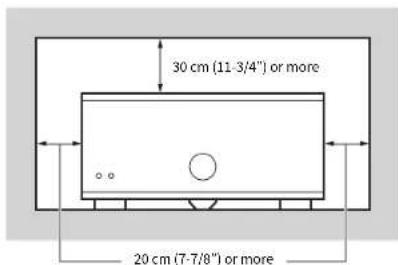
Failure to observe the above may trap heat inside the unit, causing a fire or malfunctions. Ensure that there is adequate space around the unit: at least 30 cm (11-3/4 in) on top, 20 cm (7-7/8 in) on the sides, and 20 cm (7-7/8 in) on the rear.
- Do not install the unit in places where it may come into contact with corrosive gases or salt air. Doing so may result in malfunction.
- Avoid being near the unit during a disaster, such as an earthquake. Since the unit may turn over or fall and cause injury, quickly move away from the unit and go to a safe place.
- Before moving this unit, be sure to turn off the power switch and disconnect all connection cables. Failure to observe this may damage the cables or cause you or someone else to trip and fall.
- When transporting or moving the unit always use two or more people. Attempting to lift the unit by yourself may damage your back, result in other injury, or cause damage to the unit itself.
Hearing loss
- Do not use the unit/speakers for a long period of time at a high or uncomfortable volume level, since this can cause permanent hearing loss. If you experience any hearing loss or ringing in the ears, consult a physician.
- Before connecting the unit to other devices, turn off the power for all devices. Also, before turning the power of all devices on or off, make sure that all volume levels are set to the minimum. Failing to do so may result in hearing loss, electric shock, or device damage.
- When turning on the AC power in your audio system, always turn on the unit LAST, to avoid hearing loss and speaker damage. When turning the power off, the unit should be turned off FIRST for the same reason. Failure to observe the above may cause hearing impairment or speaker damage.
Maintenance
- Remove the power plug from the AC outlet before cleaning the unit. Failure to observe this may cause electric shocks.
Handling caution

- Do not touch the surface having this label. Doing so may cause burns. The label on the device indicates that the surface to which the label is attached may become hot during operation.
- Do not insert your hand or fingers into the ventilation holes of this unit. Failure to observe this may cause injury.
- Do not insert foreign materials such as metal or paper into the ventilation holes of this unit. Failure to observe this may cause a fire, electric shocks, or malfunctions. If foreign material gets into the unit, immediately shut off the power and pull the power plug from the AC outlet and request an inspection from the dealer where you purchased the unit or from qualified Yamaha service personnel.
- Keep small parts out of the reach of infants. Your children may accidentally swallow them.
- Do not do the following:
- put heavy items on top of the equipment.
- place the equipment in a stack.
- apply unreasonable force to buttons, switches, input/output terminals, etc.
- Avoid pulling the connected cables to prevent injuries or damage to the unit by causing it to fall.
Notice
Indicates points that you must observe in order to prevent product failure, damage or malfunction and data loss.
Power supply/power cord
- If not using the unit for a long period of time, be sure to pull the power plug from the outlet. Even if the ⏻ (Standby/On) switch has been turned off, a minute current is still flowing.
Installation
- Do not use this unit in the vicinity of other electronic equipment, such as a TV, radio, or mobile phone. Failure to observe this may cause this unit or the TV or radio to produce noise.
- Do not use this unit in a location that is exposed to direct sunlight, that becomes extremely hot, such as near a heater, or extremely cold, or that is subject to excessive dust or vibration. Failure to observe this may cause the unit's panel to become deformed, the internal components to malfunction, or for operation to become unstable.
• Install this unit as far away from other electronic equipment as possible. Digital signals from this unit may interfere with other electronic equipment.
Connections
- If connecting external units, be sure to thoroughly read the manual for each unit and connect them in accordance with the instructions. Failure to properly handle a unit in accordance with the instructions could cause malfunctions.
Handling
- Do not place vinyl, plastic, or rubber products on this unit. Failure to observe this may cause discoloration or deformation in the panel of this unit.
- If the ambient temperature changes drastically (such as during unit transportation or under rapid heating or cooling) and there is a chance condensation may have formed in the unit, leave the unit for several hours without turning on the power until it is completely dry before use. Using the unit while there is condensation can cause malfunctions.
Maintenance
- When cleaning the unit, use a dry, soft cloth. Using chemicals such as benzine or thinner, cleaning agents, or chemical scrubbing cloths can cause discoloration or deformation.
Information
About content in this manual
- The illustrations and screens in this manual are for instructional purposes only.
- The company names and product names in this manual are the trademarks or registered trademarks of their respective companies.
- Software may be revised and updated without prior notice.
Read the supplied booklet "Safety Brochure" before using the unit.
Install the unit in a well ventilated, cool, dry, clean place – away from direct sunlight; heat sources, vibration, dust, moisture, and/or cold. Allow ventilation space of at least 30 cm (11-3/4") on the top, 20 cm (7-7/8") on the left and right, and 20 cm (7-7/8") on the back of the unit.
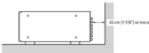
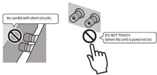
Since the unit adopts bare metallic speaker terminals, make sure keeping enough space on the back of the unit. If the speaker terminals come into contact with metal parts of the AV rack, etc., the unit will be shortened and damaged.
Also, never touch the speaker terminals when the unit is powered on since it may cause an electrical shock.
The unit does not have volume controls. Make sure you connect a device with volume control (such as a pre-amplifier) to the unit. If you connect a device without volume control (such as a CD player) directly to the unit, the volume may become excessively loud and result in damage to the unit or speakers.
CONTENTS
Accessories 9
Features 10
Part names and functions ..... 11
Front panel 11
Rear panel 12
Connections 14
Connecting speakers 15
Connecting the power cable 16
Turning on/off the unit 16
Other functions 17
Turning off the unit automatically (auto-standby function) 17
Dimming the power indicator 17
Turning on the unit in conjunction with operating other devices (trigger function) 18
Advanced speaker configuration....19
Using a speaker that supports bi-amp connection .... 19 Making a Bridge Connection Between the Front Speakers .... 19 Using two pairs of front speakers (SPEAKERS A/B) .... 20 Using three speakers for one channel (multi-speaker) .... 20
Appendix 21
Input-output signal path diagram 21
Troubleshooting 22
Specifications 23
Accessories
Check that the following accessories are supplied with the product.
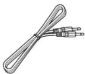
□ Power cable

"The supplied power cable varies depending on the region of purchase.
□ System control cable
□ Owner's Manual
- Due to product improvements, specifications and appearance are subject to change without notice.
- indicates precautions for use of the unit and its feature limitations.
• indicates supplementary explanations for better use.
Features
High-quality power amplifier
■High output/high audio-quality amplifier (150 W x 11 channels)
The unit provides an 11 channel power amplifier featuring a three stage Darlington current feedback circuit, with a power supply that uses the same type of toroidal transformer used in top level hi fi audio devices. The gold plated speaker connectors are also of the highest quality, delivering high grade sound.
■Balance and unbalanced connections are supported
Balanced (XLR) and unbalanced (RCA) input jacks are provided on all channels, and can be selected independently for each channel.
Balanced connections minimize the extraneous noise that can arise in the cable connection between the unit and the pre-amplifier, ensuring high-fidelity transmission of the audio signal.
Unbalanced connections utilize ground-sensing to achieve fidelity that is close to balanced transmission.
■Chassis structure that maximizes the potential of the unit's performance
The chassis features a special structure that allows the full potential of the high-quality power amplifier's potential to be revealed.
• Symmetrical power amplifier design
• Aluminum front panel and side panels
- Extremely stable feet utilizing the A.R.T. (Anti-Resonance Technology)
Expandable to meet diverse needs
■Freedom for speaker placement
Since power amplifiers of the identical specification are provided for all 11 channels, you use the unit not only for constructing a home theater setup of up to 11 channels but also for multi-room systems or any other speaker configuration to meet your needs.
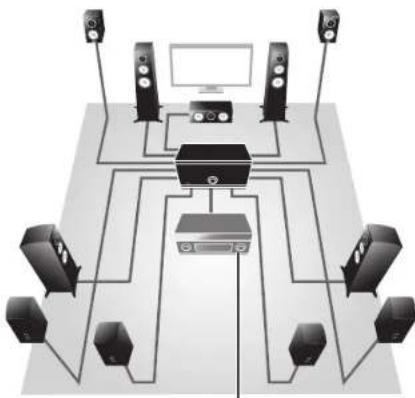
natural_image
Diagram of a multi-level audio or video streaming setup with multiple speakers, a central device, and a monitor (no text or labels)Pre-amplifier
■Support for bi-amp connections/bridge connection and multi-speaker playback
The unit provides a channel selector function that lets you utilize bi-amp connections/bridge connection or multi-speaker connections without having to connect additional cables from your pre-amplifier. Output the CH.3 input signals from both the CH.3 and CH.4 speaker terminals to realize a high sound quality bi-amp drive, or bridge the front speakers to enjoy high-powered sound.
You can also output a CH.1 (monaural) input signal from the three speakers connected to CH.1, CH.2 (L) and CH.7 (R).
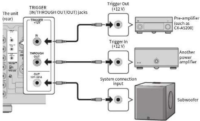
■Switch the unit's power from your pre-amplifier (trigger function)
The unit can switch its own power status in synchronization with power switching operations on another device that supports the trigger function, such as an AV pre-amplifier (TRIGGER IN). The input signal from the TRIGGER IN jack can also be output without change in a cascade connection to switch the power of another device such as a Yamaha subwoofer (THROUGH OUT). In addition, another device can be switched in synchronization when the power of the unit is switched (TRIGGER OUT), allowing you to set up a variety of systems with synchronized power switching.
Part names and functions
Front panel
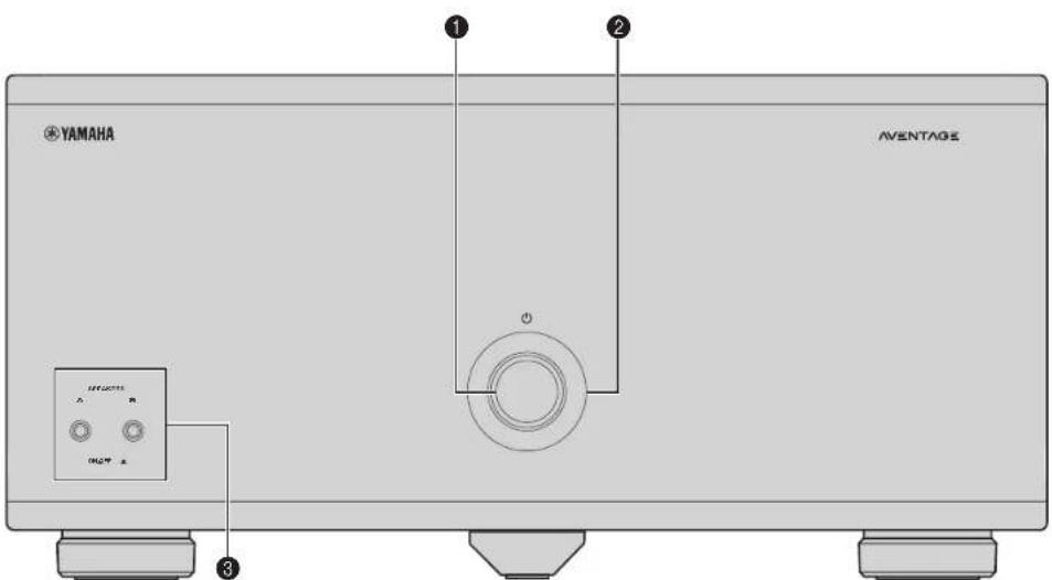
① (power) key
lums on/off (stand by) the unit (p.16).
② Power indicator
Lights up when the unit is turned on.
If the indicator blinks, the protection circuitry has been activated.
for details, see "roubleshooting" (p.22).

- You can dim the power indicator (p.17).
③SPEAKERS A/B keys
Turns on /o" the speakers connected to the CH3 A/B terminals
(p.20)

- Both the speakers (A and B) are turned off by default. Press the key to turn on the speakers you want to use.
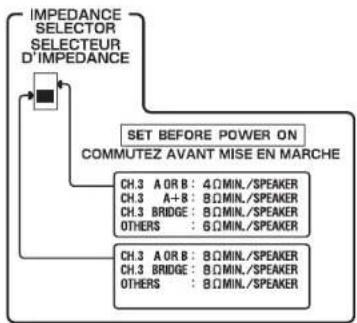
- When using two pairs of the speakers connected to the CH.3 A/B terminals at the same time, be sure to use 8-ohm speakers and set IMPEDANCE SELECTOR to the upper position (p.15).
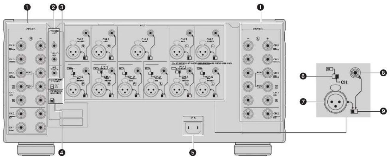
Rear panel
Caution
- Remove the unit's power cable from an AC wall outlet before making any connections or operating the switches and/or selectors.
① SPEAKERS terminals
For connecting to speakers (p.25).
② TRIGGER jacks
For connecting to devices that support the Trigger function [p.18].
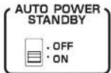
④ AUTO POWER STANDBY switch
Enables/disables the auto-standby function (p.17).
IMPEDANCE SELECTOR
Changes the unit's speaker impedance setting depending on the speakers connected (p.15).
⑤ AC IN jack
For connecting the supplied power cable (p.16).
6CH. AMP ASSIGN
(CH2, CH4 and CH6 only)
Selects the audio source input to the CH.7, CH.4 or CH.6 amplifier when applying a -amp connection and bridge connection (p.19) or a multi-speaker connection (p.20).
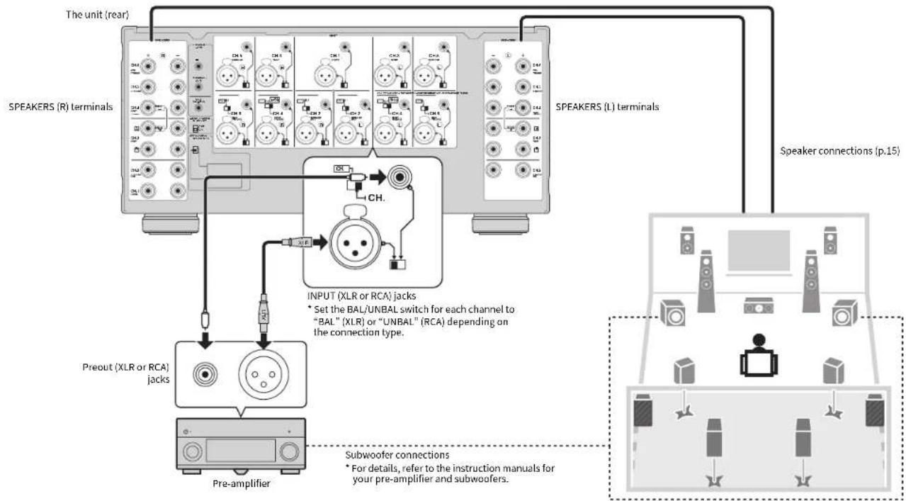
7 INPUT (XLR) jack
For connecting to a pre-amplifier with XLR output jacks (p.14). To use the XLR jack, set the corresponding BAL/UNBAL switch to "BAI".
When connecting an XLR balanced cable, match the pins and insert the "ma e" connector of the cable until you hear a click.
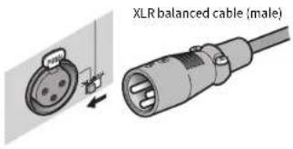

- When disconnecting the cable from the unit, hold down the PUSH button on the unit and then pull the connector out.
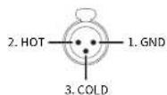
About the XLR Jacks
- The pin assignments for the XLR jacks of the unit are shown below. Before connecting an XLR balanced cable, refer to the instruction manual of your pre-amplifier and verify that its XLR output jacks are compatible with the pin assignments.
INPUT (RCA) jack
For connecting to a pre-amplifier with RCA output jacks (p.14). To use the RCA jack, set the corresponding BAL/UNBAL switch to "UNBAI".
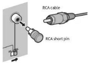

- Remove the RCA short pins attached to the INPUT (RCA) jacks before making connections. Be sure to keep them in a place inaccessible to small children who may accidentally swallow small parts.
• To protect against noise contamination, we recommend attaching the RCA short pins when the INPUT (RCA) jacks are not in use.
⑨ BAL/UNBAL switch
Switches between XI R input and RCA input for each channel (p.14).
Connections
Caution
- Remove the unit's power cable from an AC wall outlet before making any connections or operating the switches and/or selectors.
Connect a pre-amplifier and speakers to the unit.
To connect a pre-amplifier, use an XLR balanced cable (for balanced connection) or an RCA unbalanced cable (for unbalanced connection) for each channel depending on the output jacks available on your pre-amplifier.
flowchart
graph TD
    A["Speaker Connections (p.15)"] --> B["Speaker Connections (L) Terminals"]
    B --> C["Speaker Connections (R) Terminals"]
    C --> D["Speaker Connections (L) Terminals"]
    D --> E["Speaker Connections (R) Terminals"]
    E --> F["Speaker Connections (L) Terminals"]
    F --> G["Speaker Connections (R) Terminals"]
    G --> H["Speaker Connections (L) Terminals"]
    H --> I["Speaker Connections (R) Terminals"]
    I --> J["Speaker Connections (L) Terminals"]
    J --> K["Speaker Connections (R) Terminals"]
    K --> L["Speaker Connections (L) Terminals"]
    L --> M["Speaker Connections (R) Terminals"]
    M --> N["Speaker Connections (L) Terminals"]
    N --> O["Speaker Connections (R) Terminals"]
    O --> P["Speaker Connections (L) Terminals"]
    P --> Q["Speaker Connections (R) Terminals"]
    Q --> R["Speaker Connections (L) Terminals"]
    R --> S["Speaker Connections (R) Terminals"]
    S --> T["Speaker Connections (L) Terminals"]
    T --> U["Speaker Connections (R) Terminals"]
    U --> V["Speaker Connections (L) Terminals"]
    V --> W["Speaker Connections (R) Terminals"]
    W --> X["Speaker Connections (L) Terminals"]
    X --> Y["Speaker Connections (R) Terminals"]
    Y --> Z["Speaker Connections (L) Terminals"]
    Z --> AA["Speaker Connections (R) Terminals"]
    AA --> AB["Speaker Connections (L) Terminals"]
    AB --> AC["Speaker Connections (R) Terminals"]
    AC --> AD["Speaker Connections (L) Terminals"]
    AD --> AE["Speaker Connections (R) Terminals"]
    AE --> AF["Speaker Connections (L) Terminals"]
    AF --> AG["Speaker Connections (R) Terminals"]
    AG --> AH["Speaker Connections (L) Terminals"]
    AH --> AI["Speaker Connections (R) Terminals"]
    AI --> AJ["Speaker Connections (L) Terminals"]
    AJ --> AK["Speaker Connections (R) Terminals"]
    AK --> AL["Speaker Connections (L) Terminals"]
    AL --> AM["Speaker Connections (R) Terminals"]
    AM --> AN["Speaker Connections (L) Terminals"]
    AN --> AO["Speaker Connections (R) Terminals"]
    AO --> AP["Speaker Connections (L) Terminals"]
    AP --> AQ["Speaker Connections (R) Terminals"]
    AQ --> AR["Speaker Connections (L) Terminals"]
Connecting speakers
■Note on the speaker impedance
The unit supports the following speaker impedance.
- CH.3 A/B: 4 Ω or more (8 Ω or more when using CH.3 A and CH.3 B at the same time)
• BRIDGE connection: 8 Ω or more
- Other channels: 6 Ω or more
Set the IMPEDANCE SELECTOR to the upper/lower position depending on the speakers connected to the unit.
flowchart
graph TD
    A["IMPEDANCE SELECTOR SELECTEUR D'IMPEDANCE"] --> B["SET BEFORE POWER ON COMMUTEZ AVANT MISE EN MARCHE"]
    B --> C["CH.3 A OR B: 4ΩMIN./SPEAKER"]
    B --> D["CH.3 A+B: 8ΩMIN./SPEAKER"]
    B --> E["CH.3 BRIDGE: 8ΩMIN./SPEAKER"]
    B --> F["OTHERS: 6ΩMIN./SPEAKER"]
    B --> G["CH.3 A OR B: 8ΩMIN./SPEAKER"]
    B --> H["CH.3 BRIDGE: 8ΩMIN./SPEAKER"]
    B --> I["OTHERS: 8ΩMIN./SPEAKER"]
| Upper position: | Select this option when your speaker system meets one of the followings.·When connecting speakers with impedance of less than 8 Ω (4 Ω or more) to the CH.3 A or CH.3 B terminal·When using two pairs of speakers connected to the CH.3 A/B terminals at the same time (be sure to use 8-ohm speakers for both CH.3 A and CH.3 B)·When simultaneously using speakers of 8 Ω or more connected to both CH.3 A terminals and CH.4 terminals.·When connecting speakers with impedance of less than 8 Ω (6 Ω or more) to speaker terminals other than CH.3 A or CH.3 B |
| Lower position (default): | Select this option when using speakers with impedance of 5 Ω or more only. |
■Connecting speaker cables
Speaker cables have two wires. One is for connecting the negative (+) terminal of the unit and the speaker, and the other is for the positive (+) terminal. If the wires are colored to prevent confusion, connect the black wire to the negative and the other wire to the positive terminal.
① Remove approximately 10 mm (0.40 in) of insulation from the ends of the speaker cable, and twist the bare wires of the cable firmly together.
②Loosen the speaker terminal.
③ Insert the bare wires of the cable into the gap on the side (upper left or bottom right) of the terminal.
④Tighten the terminal.
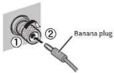
Using a banana plug
(U.S.A., Canada, China, Taiwan and Australia models only)
①Tighten the speaker terminal.
②Insert a banana plug into the end of the terminal.
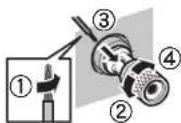
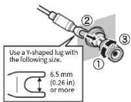
Using a Y-shaped lug connector
①Loosen the speaker terminal.
② Insert the Y-shaped lug connector into the groove between the knob and base part of the terminal.
③Tighten the terminal.
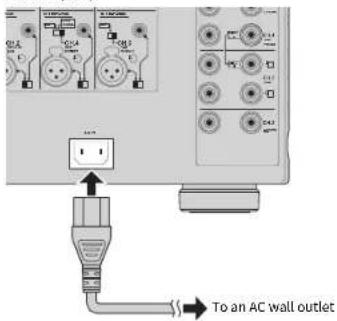
Connecting the power cable
After all the connections and switch operations are complete, connect the supplied power cable to the unit and then to an AC wall outlet.
The unit (rear)
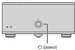
Turning on/off the unit
Press ⏻ (power) to turn on/off the unit.
When the unit is turned on, the power indicator lights up.
The unit (front)

- When an external device is connected to the TRIGGER IN jack, the unit is set to standby mode after ⏻ (power) is pressed. If you turn on the external device, the unit automatically turns on by the trigger function (p.18).
Other functions
Turning off the unit automatically (auto-standby function)
The unit will automatically go into standby mode 8 hours after the unit is turned on. To disable the auto-standby function, set the AUTO POWER STANDBY switch to "OFF".

• The auto-standby function works even if playback is ongoing.
- When the system control cable is connected to the TRIGGER IN jack, the auto-standby function does not work even if it is enabled.
Dimming the power indicator
You can dim the power indicator on the front panel of the unit.

- When an external device is connected to the TRIGGER IN jack, turn on it before performing the following procedure.
① If the unit is turned on, press ⏻ (power) to turn off it.
② Press ⏻ (power) three times within 3 seconds.
The power indicator dims.

• To cancel the dimmer, perform the procedure again.
- If the power cable is unplugged, the dimmer will be canceled.
Turning on the unit in conjunction with operating other devices (trigger function)
The trigger function can control power of the unit in conjunction with operating other devices or control power of other devices in conjunction with turning on/off the unit. If you have a power amplifier or a Yamaha subwoofer that supports the trigger function, you can use the trigger function by connecting your devices to the TRIGGER jacks with the supplied system control cable. Depending on the intended use, connect your device to one of the following TRIGGER jacks.
IN jack:
For connecting a device that supports the trigger output function (such as a pre-amplifier). If you turn on/off your device, the unit will automatically turns on/off (standby).

• This function is available only when ⏻ (power) of the unit is on (pressed down).
THROUGH OUT jack:
This jack outputs signals input from the IN jack.
If you connect a device that supports the trigger input function (such as another power amplifier), your device will automatically turn on/off in conjunction with turning on/off the device connected to the IN jack.
OUT jack:
For connecting a device that supports the trigger input function (such as a subwoofer),
If you turn on/off (standby) the unit, your device will automatically turns on/off.
flowchart
graph TD
    A["Trigger In (+12 V)"] --> B["Trigger Out (+12 V)"]
    C["Pre-amplifier (such as CX-AS200)"] --> B
    D["Another power amplifier"] --> E["System connection input"]
    F["Subwoofer"] --> E
    G["TRIGGER +12V"] --> H["TRIGGER (IN/THROUGH OUT/OUT) jacks"]
    I["THROUGH OUT"] --> H
    J["OUT 12V~40A"] --> H

• To connect multiple devices to the TRIGGER jacks, you need to prepare commercially-available monaural mini-plug cables.
Advanced speaker configuration
Caution
- Remove the unit's power cable from an AC wall outlet before making any connections or operating the switches.
Using a speaker that supports bi-amp connection
If you want to use a speaker that supports bi-amp connection to have more high quality sounds, change the CH. SELECTOR setting and connect the speaker to the corresponding pair of the SPEAKERS terminals.
(Example)
Using a speaker that supports bi-amp connection for CH.3 (R)
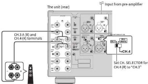
By setting the CH. SELECTOR for CH.4 (R) to "CH.3", CH.3 (R) input signals are output from both the CH.3A (R) and CH.4 (R) speaker terminals. In this case, CH.4 (R) input is not used.
Caution
- Before making bi-amp connections, remove any brackets or cables that connect a woofer with a tweeter. Refer to the instruction manual of the speakers for details. If you are not making bi-amp connections, make sure that the brackets or cables are connected before connecting the speaker cables.
Making a Bridge Connection Between the Front Speakers
You can enjoy high-powered sound by bridging the front speakers.
To make a bridge connection, set the CH. SELECTOR for CH.4 (L/R) to "CH 3 BRIDGE", and then connect speakers to the CH.3 A (L/R) and CH.4 (L/R) speaker terminals.
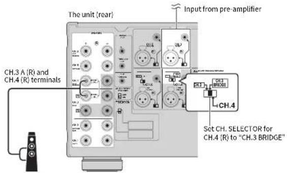
Caution
- When using a bridge connection, the terminals of CH.3 B as well as the - terminals of CH.3 A and CH.4 cannot be used.
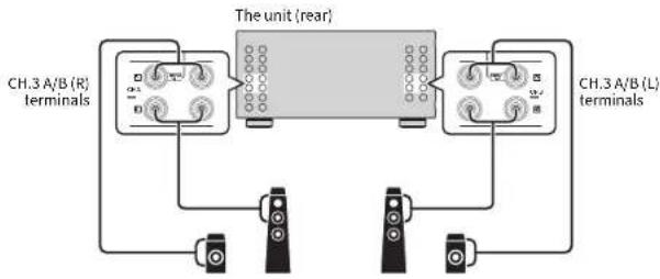
Using two pairs of front speakers (SPEAKERS A/B)
If you connect two pairs of front speakers to the CH.3 A/B terminals, you can switch the front speakers to be used by pressing SPEAKERS A/B on the front panel of the unit.

- When using two pairs of the speakers connected to the CH.3 A/B terminals at the same time, be sure to use 8-ohm speakers and set IMPEDANCE SELECTOR to the upper position (p.15).
flowchart
graph TD
    A["CH.3 A/B (R) terminals"] --> B["The unit (rear)"]
    C["CH.3 A/B (L) terminals"] --> B
    B --> D["Terminal 1"]
    B --> E["Terminal 2"]
    B --> F["Terminal 3"]
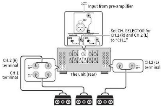
Using three speakers for one channel (multi-speaker)
If you want to use three speakers for reproducing CII.1 audio signals (such as center channel signals), change the CII. SELECTOR setting and connect the speakers to the CII.1 and CII.2 (I/R) terminals.
flowchart
graph TD
    A["Input from pre-amplifier"] --> B["Set CH. SELECTOR for CH.2 (R) and CH.2 (L) to "CH.1""]
    B --> C["The unit (rear)"]
    C --> D["CH.2 (L) terminal"]
    C --> E["CH.1 terminal"]
    E --> F["Ch.2 (R) terminal"]
    style A fill:#f9f,stroke:#333
    style B fill:#ccf,stroke:#333
    style C fill:#cfc,stroke:#333
    style D fill:#fcc,stroke:#333
    style E fill:#cff,stroke:#333
Appendix
Input-output signal path diagram
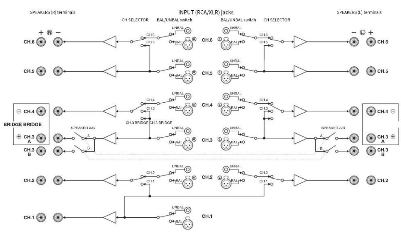
flowchart
graph LR
    subgraph SPEAKERS (R) terminals
        CH6["CH.6"] --> CH6A["CH.5"]
        CH5["CH.5"] --> CH5A["CH.4"]
        CH4["BRIDGE A"] --> CH3A["CH.3"]
        CH3B["CH.3"] --> CH3B["CH.2"]
        CH2["CH.2"] --> CH1A["CH.1"]
    end

    subgraph INPUT (RCA/XLR) jacks
        CH6A --> CH6B["CH.6"]
        CH5A --> CH5B["CH.5"]
        CH4A --> CH4B["CH.4"]
        CH3A --> CH3B["CH.3"]
        CH2A --> CH2B["CH.2"]
        CH1A --> CH1B["CH.1"]

    end

    subgraph SPEAKERS (L) terminals
        CH6L["CH.6"] --> CH6M["-"] --> CH6N["+"]
        CH5L["CH.5"] --> CH5N["+"]
        CH4L["BRIDGE"] --> CH4M["-"] --> CH4N["+"]
        CH3L["CH.3"] --> CH3M["A"] --> CH3N["A"]
        CH2L["CH.2"] --> CH2M["B"] --> CH2N["B"]
        CH1L["CH.1"] --> CH1M["A"] --> CH1N["A"]
    end

    CH6A --> CH6B
    CH5A --> CH5B
    CH4A --> CH4B
    CH3A --> CH3N
    CH2A --> CH2N
    CH1A --> CH1N
    CH6M --> CH6N
    CH4M --> CH4N
    CH3M --> CH3N
    CH2M --> CH2N
    CH1M --> CH1N

    style SPEAKERS (R) terminals fill:#f9f,stroke:#333
    style INPUT (RCA/XLR) jacks fill:#ccf,stroke:#333
Troubleshooting
Refer to the table below when the unit does not function properly.
If the problem you are experiencing is not listed below or if the instructions below do not help, turn off the unit, disconnect the power cable, and contact the nearest authorized Yamaha dealer or service center.
First, check the followings:
① The power cables of the unit and other devices (such as a pre-amplifier) are connected to AC wall outlets securely.
② The unit and other devices (such as a pre-amplifier) are turned on.
③The connectors of each cable are securely inserted in to jacks on each device.
| Problem Cause Remedy | ||
| The power does not turn on. | The protection circuitry has been activated three times consecutively. When the unit is in this condition, the power indicator on the unit blinks. | As a safety precaution, capability to turn on the power is disabled. Contact your nearest Yamaha dealer or service center to request repair. |
| The internal microcomputer has frozen, due to an external electric shock (such as lighting or excessive static electricity) or to a drop in the power supply voltage. | Disconnect the power cable from the AC wall outlet and plug it again. | |
| An external device is connected up the TRIGCFR (IN) jack. | Press down (power) on the unit and then turn on the external device. | |
| The power turns off (standby mode) immediately. | The unit was turned on while a speaker cable was shorted. | Twist the bare wires of each speaker cable firmly and reconnect to the unit and speakers (p.15). |
| The unit was shorted because the speaker terminals come into contact with metal parts of the AV rack, etc. | Keep enough space on the back of the unit (p.9). | |
| The unit enters standby mode automatically. | The auto-standby function worked. | To disable the auto-standby function, set the AUTO POWER STANDBY switch to "OFI" (p.17). |
| The protection circuitry has been activated because the volume of the external device connected to the unit is too high. | Turn down the volume of the external device. | |
| The protection circuitry has been activated because the temperature inside of the unit is too high. | Install the unit in a wall ventilated, place and a low enough ventilation space around the unit (p.8). | |
| No sound. | The BAL/UNBAL switch setting is not correct. | Change the BAL/UNBAL switch setting so that it matches the connections (p.14). |
| No sound is coming from a specific speaker. | The speakers connected to the CH.3 A/B terminals are turned off. Press SPEKERS A/B to turn on the speakers (p.20). | |
| The XLR balanced cable (or RCA unbalanced cable) connecting the unit and pre-amplifier is defective, or the speaker cable connecting the unit and speaker is defective. | If there is no problem with the connection, replace with another cable. | |
| Another channel sound is coming from a specific speaker. | The CH SELECTOR setting is not correct. Change the CH SELECTOR setting so that it matches your speaker system (p.19). | |
Specifications
Input jacks
• Audio
Analog RCA (Unbalance) x 11
Analog XLR (Balance) x 11 (2:GND, 2:HOT, 3:COLD)
Output jacks
• Audio
Speaker Out x 11 ch
[13 Terminals: CH.1, CH.2] [R], CH.3-A] [R], CH.3-B] [R], CH.4] [R] to CH.6] [R]
Other jacks
• TRIGGER OUT x | (112 V/C) A max.)
• TRIGGFR IN × I (+12 V In)
• TRIGGFRTHROUGHOUT×1
Audio Section
• Rated Output Power (2-channel driven)
(20 Hz to 20 kHz, 0.06% | HD, 6 Ω)
CH1 1/0 W
CH2 (L/R) 1/0 W
CH3(L/R) 170W
CH4(L/K) 10W
CHS (L/K) 10W
CH.5 (L/K) 10W
(20 Hz to 20 kHz, 0.06% (HD, 8Ω))
CH.1 150 W
CH2(L/R) 150 W
CH3(L/R) 150 W
CH4(L/R) 150 W
CH5(L/R) 150 W
CH5(L/R) 150 W
(1 kHz, 0.9% THD, 8 Ω)
CH1 170 W
CH2(L/R) 170 W
CH3(L/R) 170 W
CH4(L/R) 170 W
CH5 (L/R) 170 W
CH₃ (L/R) 170 W
• Rated Output Power (I-channel driven)
(1 kHz, 0.9% THD, 5 Ω)
CH.1 730 w/ch
CH2 (I/R) 230 W/ch
CH3(1/R) 230 W/dt
CHA (J/R) 230 W/ch
CH.5 (I/R) 230 W/ch
CH.6 (I/R) 230 W/ch
(1 kHz, 0.9% THD, 8 Ω)
CH.1 130 w/ch
CH2(U/R) 190 W/ch
CH3 (1/R) 100 W/d
CHA (1/R) 190 W/d
CH₃ (R) 190 W/d
CH₃O (L/R) 100 W/d
U.K., Europe and Russia markets
(1 kHz, 0.9% THD, 4 Ω)
CH.3(L/R) 250 W/ch
- Rated Output Power (2-channel BRIDGL driven)
(20-20 kHz, 0.06% THD, 8 Ω)
CH3A (+) and C-14 (-) (L/R) 200 W/ch
(1kHz, 0.5% II D, 8Ω)
CH3A (+) and C-14 (-) (L/R) 240 W/ch
• Maximum Effective Output Power (1 channel driven, ULTA)
China, Taiwan, Korea, Asia, Brazil, Central and South America and General models
(1 kHz, 10% HD, 6 Ω)
CH _2 1 280 w/ch
CH2(L/K) 280 W/ch
CH3(L/R) 280 W/ch
CH4(L/R) 280 W/ch
CH₃(L/R) 280 W/ch
CH6(L/R) 280 W/ch
(1 kHz, 10% THD, 8 Ω)
CH1 230 w/ch
CH2(L/R) 230 W/ch
CH3(L/R) 230 W/ch
CH4 (L/R) 230 W/ch
CH5(L/R) 230 W/ch
CH6(1/R) 230 W/ch
• Dynamic Power (IHF)
I-channel driven (8/6/4/2 Ω) 190/250/350/500 W
• Damping Factor
All Channels, 1 kHz, 8Ω.... 130 or more
- Input Sensitivity / Input Impedance
Unbalance (1 kHz, 100 W/8 Ω)....1.0 V/47 kΩ
Balance (1 kHz, 100 W/6 Ω) 7.0 V/47 kΩ
• Maximum Input Signal
Unbalance (1 kHz, 0.5% THD, 8 Ω) 1.3 V
Balance (1 kHz, 0.5% THD, 8 Ω) 2.6 V
• Frequency Response (10 Hz to 100 kHz) 10/-3 dB
• Total Harmonic Distortion (70 W/8 Ω) 0.015% or less
• Signal to Noise Ratio (HF-A Network)
[Input Shorted 1 kΩ, Reference Level 150 W/8 Ω]
116 dB or more
• Residual Noise (HF A Network)
Speaker Out (Inout Shorted) 60 u/v or less
• Channel Separation Input 5.2 kΩ Shorted, 1 kHz/10 kHz
90/75 dB or mom
• Gain 29.1 dB
General
• Power Supply
[U.S.A. and Canada models]....AC 120 V, 60 Hz
[Taiwan, Central and South America and Brazil models]
AC 110 to 120 V, 50/60 Hz
[China model].....AC 220 V, 50 Hz
[Korea model]......AC 220 V, 60 Hz
Australia model.....AC 240 V, 50 Hz
U.K., Europe and Swiss a models]....AC 230 V, 50 Hz
Asia and General model.....AC 220 to 240 V, 50/60 Hz
• Power Consumption 650 W
• Standby Power Consumption....0.1 W (Typical)
• Maximum Power Consumption (All. Channel. driven, 10% THD)
[Taiwan, Brazil, Asia, Central and South America and General modes]
1500 W
• Power Consumption (No Signals)....../5 W (Typical)

• Dimensions (W x H x D)
435 x 211 x 464 mm (17-1/8" x 8-1/4" x 18-1/4")
* Including legs and protrusions
• Weight 26.4 kg (58.2 lbs)
* Specifications are subject to change without notice.
PRÉCAUTIONS CONCERNANT LA SÉCURITÉ
natural_image
Diagram of a multi-level audio or audio setup with multiple speakers, audio equipment, and a central monitor (no text or labels)Préamplificateur
① Bouton ⏻ (alimentation)
Attention
(1 kHz, 0HT 0.9%, 8 Ω)
CH1 170 W
CH2(L/R) 170 W
CH3(L/R) 170 W
CH4(L/R) 170 W
CH.5 (L/R) 170 W
CH5 (J/R) 170 W
(1 kHz, DHT 0.9%, 8Ω)
CH.1....190 W/voie
CH2 (I/R)....190 W/voie
CH.2 (I / R)....190 W/voie
CH4 (I/R) 190 W/voie
CHS (I/R) 130 W/voie
CH.6 (L/R) 130 W/voie
(1 kHz, DHT 0.9%, 4 Ω)
CH.3 (L/R)....230 W/voie
(1 kHz, DHT 10%, 6 Ω)
CH.1 280 W/vole
CH2(L/R) 280 W/voic
CH3 (L/R) 280 W/volc
CH4(L/R) 280 W/vole
CH5(L/R) 280 W/vole
CH6(L/R) 280 W/voie
(1 kHz, DHT 10%, 8 Ω)
CH _2 230 W/voie
CH2(L/R) 230 W/voie
CH3(L/R) 230 W/voie
CH4 (L/R) 230 W/voie
CH5 (L/R) 230 W/voie
CH6(II/R) 230 W/voie
Symétrique (1 kHz, 100 W/8 Ω)....2,0 V/47 kΩ
natural_image
Diagram of a multi-level audio or video system setup with speakers, amplifiers, and a central device (no text or labels visible)Preamplificador
Precaución
(1 kHz, 0.9% THD, 8 Ω)
CH1 170 W
CH2(LiR) 170 W
CH3(LiR) 170W
CH4(L/R) 170 W
CH.5 (L/R) 170 W
CH₆(L/R) 170 W
(1 kHz, 0.9 % THD, 6 Ω)
CH.1 230 W/cana
CH2 (I /R) 230 W/canal
CH3(I/R) 230 W/canal
CH4(II/R)....230 W/caral
CH.5 (I /R)....230 W/canal
CH.6 (I /R)....230 W/caral
(1 kHz, 0.9 % THD, 8 Ω)
CH.1 190 W/cena
CH2 (I/R) 190 W/canal
CH.2 (I /R)....190 W/canal
CH4 (I/R) 190 W/coral
CHS (I /R)....190 W/coral
CH.6 (I /R)....190 W/caral
(1 kHz, 0.9 % THD, 4 Ω)
CH2 (L/R) 290 W/canal
(1kHz, 0.9% THD, 8Ω)
CH3A (+) y CH4 (+) [L/R] 240 W/canal
(1 kHz, 10 % THD, 6 Ω)
CH.1 280 W/cara.
CH2 (L/R) 280 W/canal
CH3 (L/R) 280 W/canal
CH4 (L/R) 280 W/canal
CH₃ (L/R) 280 W/canal
CH₃6 (L/R) 280 W/canal
(1 kHz, 10 % THD, 8 Ω)
CH _2 230 W/cana
CH2(L/R) 230 W/canal
CH3 (L/R) 230 W/canal
CH4 (L/R) 230 W/canal
CH5 (L/R) 230 W/canal
CH6(II/R) 230 W/canal
• Potenciadánamica (IHF)
Señal en I canal (8/6/1/2 Ω) 190/250/350/500 W
5in balancear (1 kHz, 100 W/8 Ω) 1.0 V/47 kΩ
Balanceada (1 kHz, 100 W/8 Ω)....2.0 V/47 kΩ
Sin balancear (1 kHz, 0.5% THD, 8 Ω)....1.3 V
Balanceada (1 kHz, 0.5% THD, 8 Ω) 2.6 V
natural_image
Diagram of a multi-level audio or video streaming setup with multiple speakers, a central device, and a monitor (no text or labels)Pré-amplificador
7 Conector INPUT (XLR)
(20 Hz a 20 kHz, 0.06% THD, 6 Ω)
C11.1....1/0W
CH2 (L/R) 10W
CH3(L/K) 1/0W
CH4(L/K) 10W
CHS (L/K) 10W
CH.5 (L/K) 10W
(20 Hz a 20 kHz, 0.06% | HD, 8 Ω)
CH.1 150 W
CH2(L/R) 150 W
CH.3(L/R) 150 W
CH4(L/R) 150 W
CH.5 (L/R) 150 W
CH₃ (L/R) 150 W
(1 kHz, 0.9% THD, 8 Ω)
CH1 170 W
CH2(LiR) 170 W
CH3(L/R) 170 W
CH4(L/R) 170 W
CH5(L/R) 170 W
CH₃ (L/R) 170 W
(1 kHz, 0.9% THD, 5 Ω)
CH.1 230 W/cara
CH2 (I/R) 230 W/canal
CH3 (I /R) 230 W/canal
CH4(II/R) 230 W/canal
CH.5 (I /R)....230 W/canal
CH.6 (I /R)....230 W/caral
(1 kHz, 0.9% THD, 8 Ω)
CH.1....190 W/czra
CH2 (I/R) 190 W/coral
CH2 (I/R) 190 W/coral
CH4 (I/R) 190 W/coral
CHS (I /R) 190 W/coral
CH.6 (I /R)....190 W/canal
Modelos do Reino Único, Europa e Rússica
(1 kHz, 0.9% THD, 4 Ω)
CH.3 (L/R)....290 W/canal
(20-20 kHz, 0.05% [HD, 8 Ω])
CH3A (+) e C 14 (+) (L/R) 200 W/canal
(1 kHz, 0.9%) THD, 8 Ω;
CH3A (+) e C 14 (+) (L/R)....240 W/canal
(1 kHz, 10% HD, 6 Ω)
CH.1 280 W/cara
CH2 (L/R) 280 W/canal
CH3 (L/R) 280 W/canal
CH4 (L/R) 280 W/canal
CH₃ (L/R) 280 W/canal
CH6 (L/R) 280 W/canal
(1 kHz, 10% THD, 8 Ω)
CH _2 230 W/cara
CH2(L/R) 230 W/canal
CH3 (L/R) 230 W/canal
CH4 (L/R) 230 W/canal
CH5 (L/R) 230 W/canal
CH6(II/R) 230 W/canal
Desbalanceado (1 kHz, 100 W/8 Ω)....1,0 V/47 xΩ
Balanceco (1 kHz, 100 W/8 Ω)....2,0 V/47 kΩ
natural_image
Diagram of a multi-level audio or audio system with speakers, amplifiers, and a central device (no text or labels)Предусилитель
Предупреждение
CH.5 (L/R)....1/0 BT
natural_image
Diagram of a multi-level audio or video recording setup with speakers, amplifiers, and a central device (no text or labels)前置放大器
■支持双功放连接 / 桥接和多声道播放
模拟 XLR (平衡)×11 (1:GND, 2:HOT, 3:COLD)
输出插孔
·音频
音箱输出 x 11 ch
(13 个终端:CH.1、CH.2[L/R]、CH.3-A[L/R]、CH.3-B[L/R]、
CH.4[L/R] 至 CH.6[L/R])
其他插孔
- TRIGGER OUT x 1 (+12 V/0.1 A 最大)
• TRIGGER IN x 1 (+12 V In)
• TRIGGER THROUGH OUT × 1
音频部分
- 额定输出电源 (2 声道驱动)
(20 Hz 至 20 kHz, 0.065 THD, 6 Ω)
CH. 1.... 170 W
CH. 2 (L/R) 170 W
CH. 3 (L/R) 170 W
CH. 4 (L/R) 170 W
CH. 5 (L/R) 170 W
CH. 6 (L/R) 170 W
(20 Hz 至 20 kHz, 0.06% THD, 8 Ω)
CH. 1.... 150 W
CH. 2 (L/R) 150 W
CH. 3 (L/R) 150 W
CH. 4 (L/R) 150 W
CH.5 (L/R) 150 W
CH. 6 (L/R) 150 W
(1 kHz, 0.95 THD, B Ω)
CH. 1.... 170 W
CH. 2 (L/R) 170 W
CH. 3 (L/R) 170 W
CH. 4 (L/R) 170 W
CH. 5 (L/R) 170 W
CH. 6 (L/R) 170 W
- 额定输出电源(1 声道驱动)
(1 kHz, 0.9% THD, 6 Ω)
CH. 1 230 W/ch
CH. 2 (L/R) 230 W/ch
CH. 3 (L/R) 230 W/ch
CH. 4 (L/R) 230 W/ch
CH. 5 (L/R) 230 W/ch
CH. 6 (L/R) 230 W/ch
(1 kHz, 0.9% THD, 8 Ω)
CH. 1 190 W/ch
CH. 2 (L/R) 190 W/ch
CH. 3 (L/R) 190 W/ch
CH. 4 (L/R) 190 W/ch
CH. 5 (L/R) 170 W/ch
CH. 6 (L/R) 170 W/ch
[英国、欧洲和俄罗斯型号]
(1 kHz, 0.9% THD, 4 Ω)
CH. 3 (L/R) 270 W/ch
(20-20 kHz, 0.06% THD, 8 Ω)
CH3A (+) 和 CH4 (+) (L/R) 200 W/ch
(1kHz, 0.9% THD, 8 Ω)
CH3A (+) 和 CH4 (+) (L/R) 240 W/ch
(1 kHz, 10% THD, 6 Ω)
CH. 1 280 W/ch
CH. 2 (L/R) 280 W/ch
CH. 3 (L/R) 280 W/ch
CH. 4 (L/R) 280 W/ch
CH. 5 (L/R) 280 W/ch
CH. 6 (L/R) 280 W/ch
(1 kHz, 10% THD, 8 Ω)
CH. 1 230 W/ch
CH. 2 (L/R) 230 W/ch
CH. 3 (L/R) 230 W/ch
CH. 4 (L/R) 230 W/ch
CH. 5 (L/R) 230 W/ch
CH. 6 (L/R) 230 W/ch
- 动态功率(IHF)
1 通道驱动 (8/6/4/2 Ω) 190/250/350/500 W
- 阻尼系数
natural_image
Top-down diagram of a multi-level audio or video recording setup with speakers, amplifiers, and a central device (no text or labels visible)프리 앱프
다양한 요구에 맞춘 확장 가능성
■자유로운 스피커 배치
주의
(1 kHz, 0.9% THD, 8 Ω)
CH.1 170 W
CH.2 (L/R) 170 W
CH.3 (L/R) 170 W
CH.4 (L/R) 170 W
CH.5 (L/R) 170 W
CH.6 (L/R) 170 W
-정격 출력 전원 (1 체널 구동)
(1 kHz, 0.9% THD, 6 Ω)
CH.1 230 W/ch
CH.2 (L/R) 230 W/ch
CH.3 (L/R) 230 W/ch
CH.4 (L/R) 230 W/ch
CH.5 (L/R) 230 W/ch
CH.6 (L/R) 230 W/ch
(1 kHz, 0.9% THD, 8 Ω)
CH.1 190 W/ch
CH.2 (L/R) 190 W/ch
CH.3 (L/R) 190 W/ch
CH.4 (L/R) 190 W/ch
CH.5 (L/R) 190 W/ch
CH.6 (L/R) 190 W/ch
[영국,유럽 및 러시아 모델]
(1 kHz, 0.9% THD, 4 Ω)
CH.3 (L/R) 290 W/ch
(20-20 kHz, 0.06% THD, 8 Ω)
CH3A (+) and CH4 (+) (L/R).....200 W/ch
(1kHz, 0.9% THD, 8 Ω)
CH3A (+) and CH4 (+) (L/R)....240 W/ch
(1 kHz, 10% THD, 6 Ω)
CH.1 280 W/ch
CH.2 (L/R) 280 W/ch
CH.3 (L/R) 280 W/ch
CH.4 (L/R) 280 W/ch
CH.5 (L/R) 280 W/ch
CH.6 (L/R) 280 W/ch
(1 kHz, 10% THD, 8 Ω)
CH.1....230 W/ch
CH.2 (L/R) 230 W/ch
CH.3 (L/R) 230 W/ch
CH.4 (L/R) 230 W/ch
CH.5 (L/R) 230 W/ch
CH.6 (L/R) 230 W/ch
· 동적 출력 (IHF)
1-채널 구동 (8/6/4/2 Ω)....190/250/350/500 W
·감쇠 인자
Information for users on collection and disposal of old equipment:

This symbol on the products, packaging, and/or accompanying documents means that used electrical and electronic products should not be mixed with general household waste.
For proper treatment, recovery and recycling of old products, please take them to applicable collection points, in accordance with your national legislation.
By disposing of these products correctly, you will help to save valuable resources and prevent any potential negative effects on human health and the environment which could otherwise arise from inappropriate waste handling.
For more information about collection and recycling of old products, please contact your local municipality, your waste disposal service or the point of sale where you purchased the items.
For business users in the European Union:
If you wish to discard electrical and electronic equipment, please contact your dealer or supplier for further information.
Information on Disposal in other Countries outside the European Union:
This symbol is only valid in the European Union. If you wish to discard these items, please contact your local authorities or dealer and ask for the correct method of disposal.
(weee_eu_en_02)
Important Notice: Guarantee Information for customers in EEA\* and Switzerland
English
For detailed guarantee information about this Yamaha product, and Pan-EEA* and Switzerland warranty service, please either visit the website address below (Printable file is available at our website) or contact the Yamaha representative office for your country.
* EEA: European Economic Area
https://download.yamaha.com/
Manual Development Group
© 2018 Yamaha Corporation
Published 10/2018 AM-A0
VAA2420


