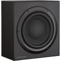
ISW4 - Subwoofer BOWERS & WILKINS - Free user manual and instructions
Find the device manual for free ISW4 BOWERS & WILKINS in PDF.
| Product type | In-wall subwoofer |
| Brand | Bowers & Wilkins |
| Model | ISW-4 |
| Dedicated amplifier | SA250 (power amplifier for subwoofer) |
| Installation type | Flush-mounted in wall (hollow partition or solid wall) |
| Power supply | Mains (power cord, country-specific) |
| Amplifier power | 250 W RMS (estimated) |
| Controls and adjustments | Volume, low-pass crossover frequency, filter on/off, phase (0°/180°), bass boost (A/B/C), equalization Movie/Music, standby/On/Auto |
| Audio inputs | Unbalanced RCA, balanced XLR, 12 V Trigger (3.5 mm jack) |
| Audio outputs | 4-pole Speakon, screw terminals (2 pairs), RCA and XLR for daisy chain |
| Indicators | Operation (green), Fault (red) |
| Features | Auto standby, 12 V Trigger switching, Movie/Music mode |
| Package contents | Wall frame, front panel, mounting template, adhesive logo, paint cover, M5 nuts, Back Box, sealing gasket, SA250, power cable, 4-pole Speakon plug, rack ears, screws, handles, rubber caps |
| Warranty | 5 years for speakers, 2 years for electronic components |
| Cleaning | Soft, dry cloth |
| Safety instructions | Read the manual, do not expose to moisture, unplug during storms, use identical parts for replacement |
| Operating conditions | Ambient temperature, avoid humidity and condensation |
Frequently Asked Questions - ISW4 BOWERS & WILKINS
User questions about ISW4 BOWERS & WILKINS
0 question about this device. Answer the ones you know or ask your own.
Ask a new question about this device
Download the instructions for your Subwoofer in PDF format for free! Find your manual ISW4 - BOWERS & WILKINS and take your electronic device back in hand. On this page are published all the documents necessary for the use of your device. ISW4 by BOWERS & WILKINS.
USER MANUAL ISW4 BOWERS & WILKINS
Title, first name, surname
Address
Town, postcode, country
e-mail address
Product details
Model
Serial number
Date of purchase
Dealer details
Dealer name
Address
Town, postcode, country
e-mail address
Dealer stamp
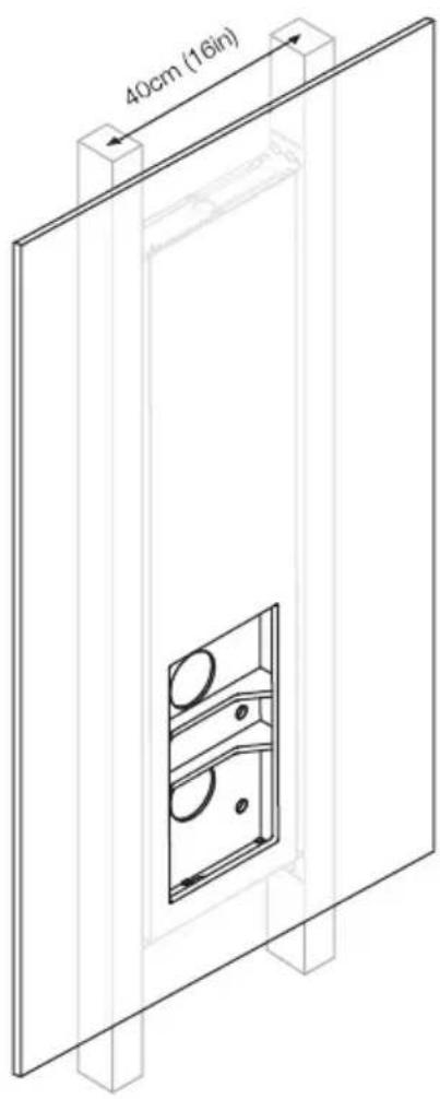
Figure 1
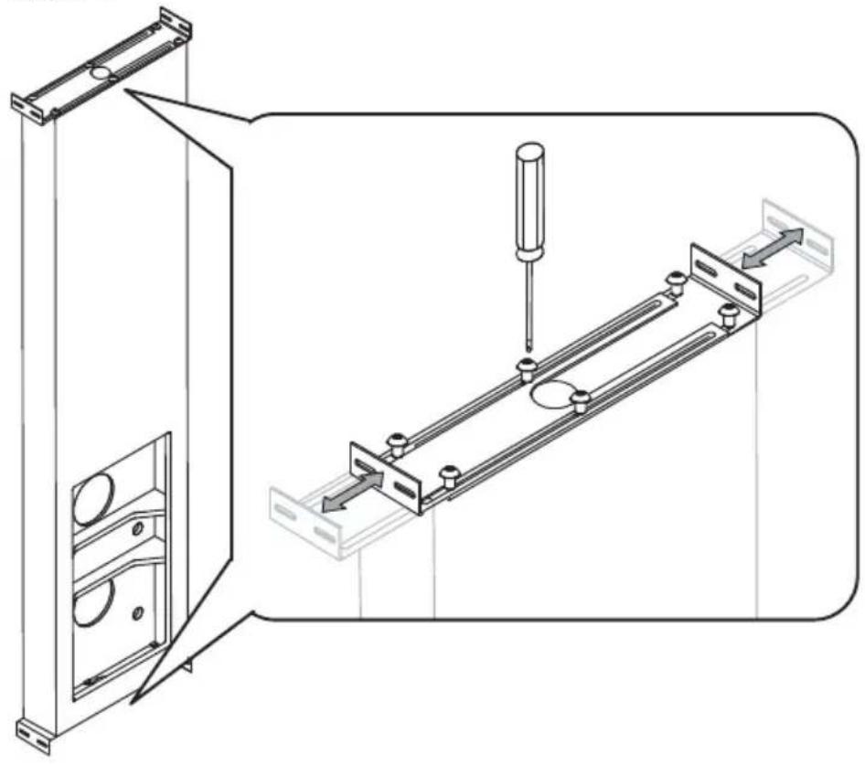
Figure 2
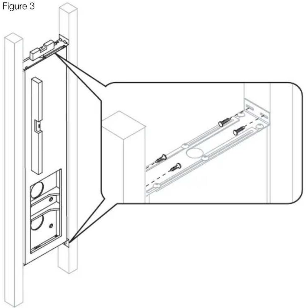
Figure 3
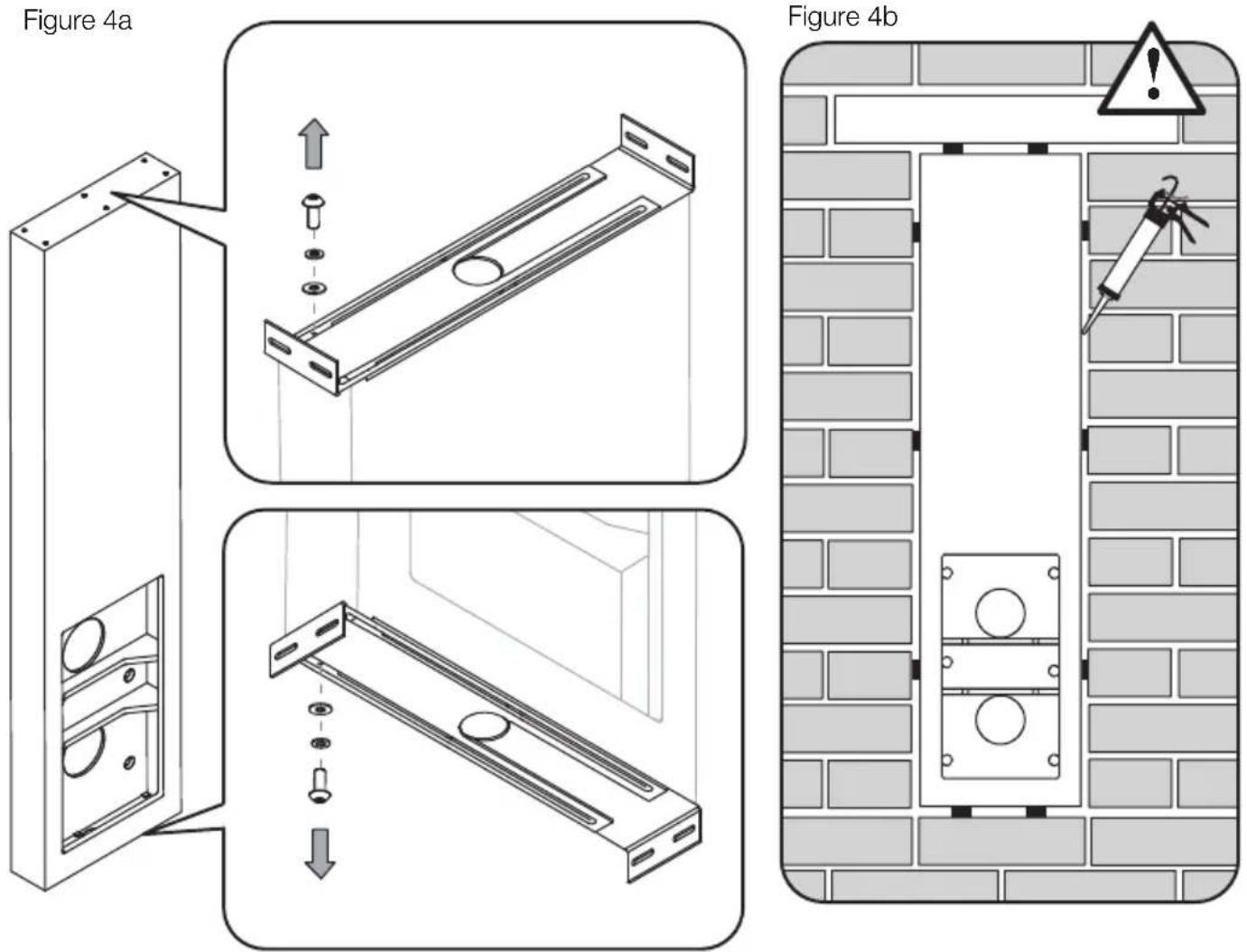
Figure 4a
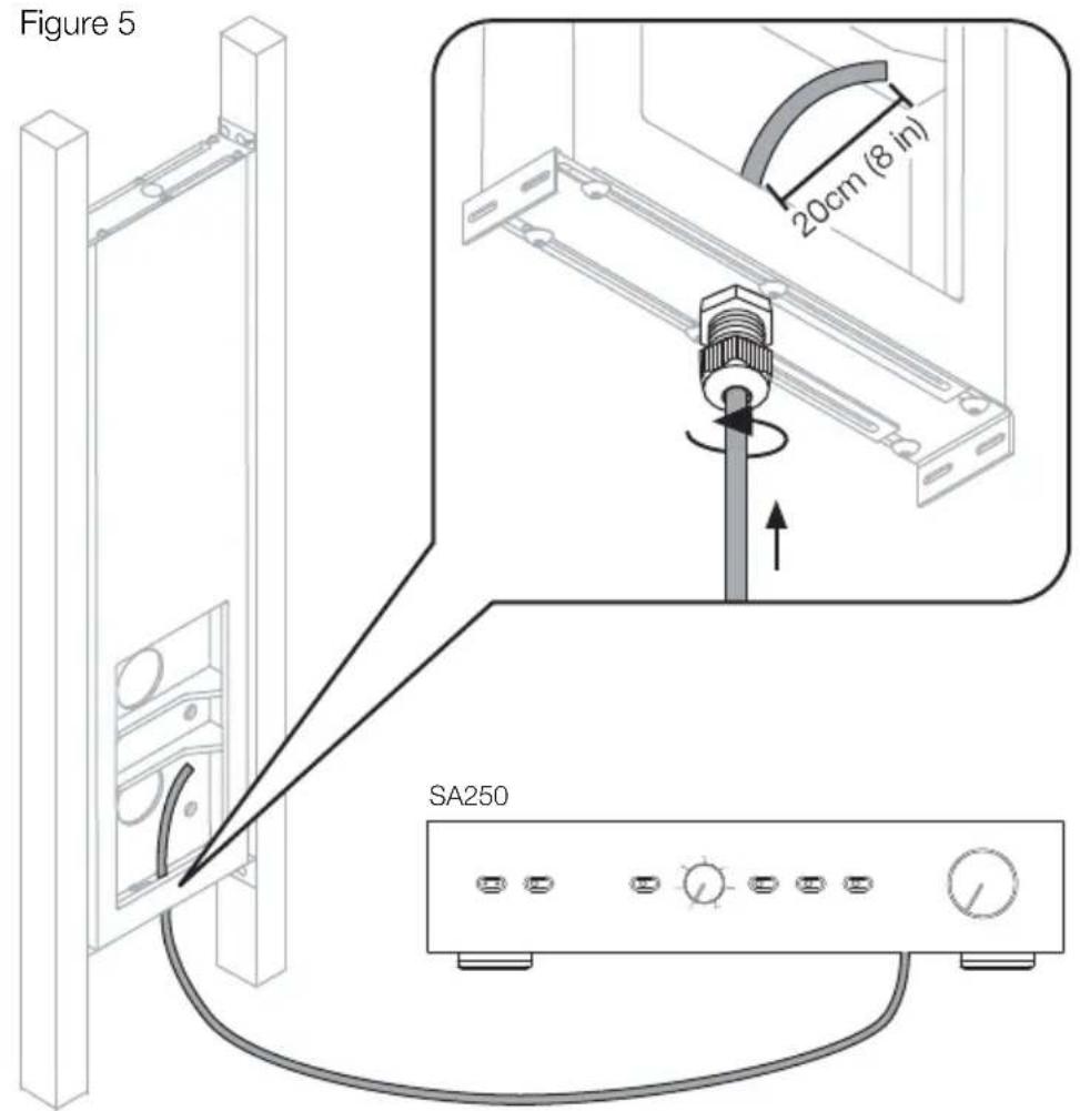
Figure 5
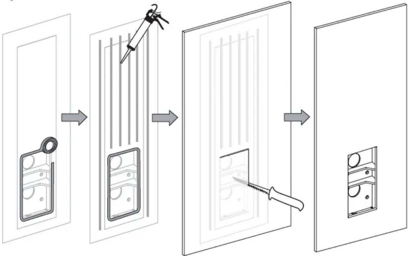
Figure 6a
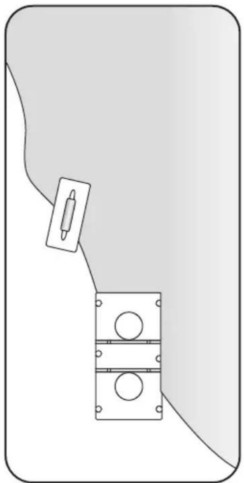
Figure 6b
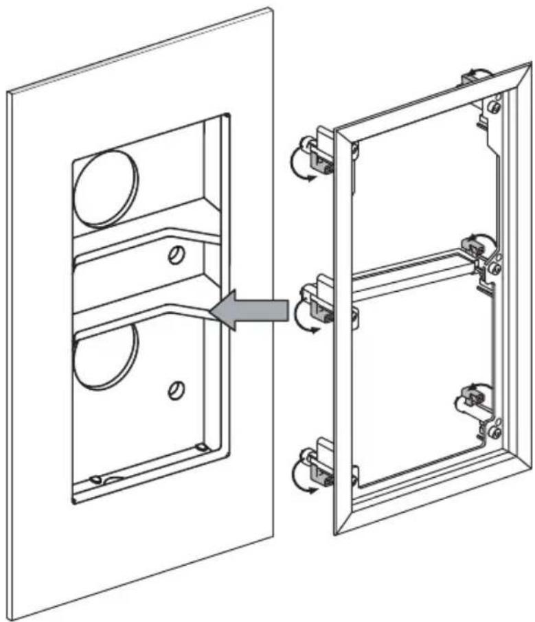
Figure 7a
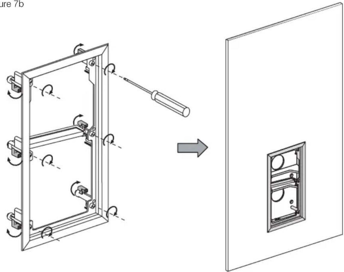
Figure 7b
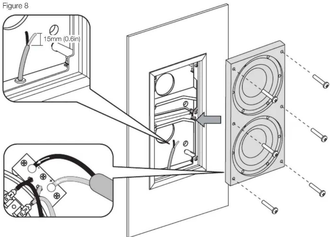
Figure 9
Figure 10
Neutrik® Speakon® Connector NL4FC
ISW-4
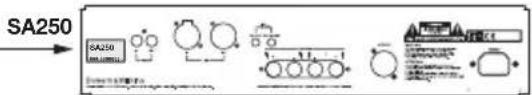
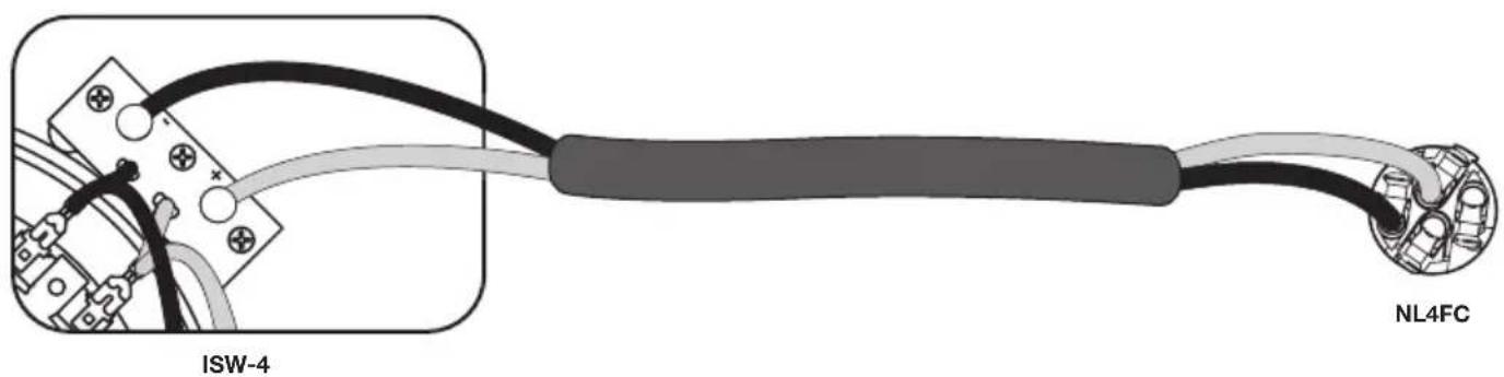
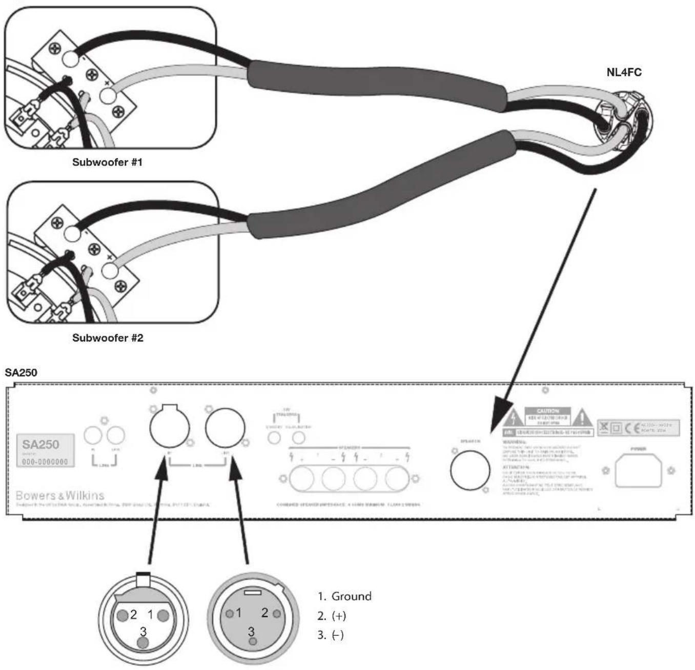
Figure 11
Contents
English
Installation and
Setup Manual 6
Limited Warranty 11
Français
of Conformity ....101-102
Technical
Specifications ....103-104
English Installation and Setup Manual
Important Safety Instructions
- Read these instructions.
- Keep these instructions.
- Heed all warnings.
- Follow all instructions.
- Do not use this apparatus near water.
- Clean only with dry cloth.
- Do not block any ventilation openings. Install in accordance with the manufacturer's instructions.
- Do not install near any heat sources such as radiators, heat registers, stoves, or other apparatus (including amplifiers) that produce heat.
- Do not defeat the safety purpose of the polarized or grounding-type plug. A polarized plug has two blades with one wider than the other. A grounding type plug has two blades and a third grounding prong. The wide blade or the third prong are provided for your safety. If the provided plug does not fit into your outlet, consult an electrician for replacement of the obsolete outlet.
- Protect the power cord from being walked on or pinched particularly at plugs, convenience receptacles, and the point where they exit from the apparatus.
- Only use attachments/accessories specified by the manufacturer.
- Use cart with the cart, stand,

tripod, bracket, or table specified by the manufacturer, or sold with the apparatus. When a cart is used, use caution when moving the cart/mbination to avoid injury from
- Unplug this apparatus during lightning storms or when unused for long periods of time.
- Refer all servicing to qualified service personnel. Servicing is required when the apparatus has been damaged in any way, such as power-supply cord or plug is damaged, liquid has been spilled or objects have fallen into the apparatus, the apparatus has been exposed to rain or moisture, does not operate normally, or has been dropped.
- Do not expose this apparatus to dripping or splashing and ensure that no objects filled with liquids, such as vases, are placed on the apparatus.
-
To completely disconnect this apparatus from the AC Mains, disconnect the power supply cord plug from the AC receptacle.
-
The mains plug of the power supply cord shall remain readily operable.
- Do not expose batteries to excessive heat such as sunshine, fire or the like.
The lightning flash with arrowhead symbol within an equilateral triangle, is intended to alert the user to the presence of uninsulated "dangerous voltage" within the product's enclosure that may be of sufficient magnitude to constitute a risk of electric shock to persons.

The exclamation point within an equilateral triangle is intended to alert the user to the presence of important operating and maintenance (servicing) instructions in the literature accompanying the product.
WARNING: To reduce the risk of fire or electric shock, do not expose this apparatus to rain or moisture.
- When replacement parts are required, be sure the service technician has used replacement parts specified by the manufacturer or have the same characteristics as the original part. Unauthorised substitutions may result in fire, electric shock or other hazards.
- For continued protection against fire hazard, use fuses only of the correct type and rating. Mains fuses are located inside the appliance as well as on its back panel. Replacement of the internal fuse should be entrusted to an authorised operative. User-replaceable fuse types are shown in the specification.
- Isolation of the appliance from the power supply is by means of removal of the power cord from the rear of the appliance or removal of the power cord from the wall power outlet. Either the wall outlet or the rear of the appliance must remain freely accessible at all times while the apparatus is in use.
- This product should be operated only from the type of power source indicated by the marking adjacent to the power cord entry. If you are not sure of the type of power supply to your home, consult your product dealer or local power company.
- Do not overload wall outlets, extension cords or integral convenience receptacles, as this can result in a risk of fire or electric shock.
-
Magnetic fields - The product creates a stray static magnetic field. Do not place any object that may be damaged by this magnetic field (eg cathode ray tube televisions or computer monitors, audio and video tapes and swipe cards) within 0.5m (2 feet) of the appliance. The appliance may cause distortion of cathode ray tube images beyond this distance. LCD and Plasma screens are not affected.
-
Mounting - Do not place this product on an unstable stand, tripod, bracket or table. The product may fall causing serious injury and serious damage. Any mounting of the product should follow the manufacturer's instructions.
Do not expose the device to rain, use it near water or in damp or wet conditions, or place containers on it containing liquids which might spill into any openings.
When setting up the device, make sure that the AC outlet you are using is easily accessible. If some trouble or malfunction occurs, immediately turn off the power switch and disconnect the plug from the outlet. Even when the power switch is turned off, electricity is still flowing to the product at the minimum level. When you are not using the device for a long time, make sure to unplug the power cord from the wall AC outlet.
Introduction
Dear customer,
Thank you for choosing Bowers & Wilkins. Please read this manual fully before unpacking and installing the product. It will help you to optimise its performance. B&W maintains a network of dedicated distributors in over 60-countries who will be able to help you should you have any problems your dealer cannot resolve.
Environmental Information


All B&W products are designed to comply with international directives on the Restriction of Hazardous Substances
(RoHS) in electrical and electronic equipment and the disposal of Waste Electrical and Electronic Equipment (WEEE). These symbols indicate compliance and that the products must be appropriately recycled or processed in accordance with these directives. Consult your local waste disposal authority for guidance.
This manual covers the ISW-4 in-wall subwoofer, its Back Box and its matching SA250 automated rack mount power amplifier.
Carton Contents
The product is shipped in three cartons: the ISW-4 Carton, the Back Box Carton and the SA250 Carton
In addition to the Driver Panel, check the ISW-4 carton for:
This manual
1xWallFrame
1xGrille
1 x Cut-out template
1 x Adhesive B&W logo
1 x Paint mask
6 x M5 bolts
In addition to the Back Box itself, check Back Box Carton for:
1 x Installation Instructions
1 x Gasket roll
In addition to the SA250 itself, check SA250 Carton for:
1 x Mains Cable
1 x Four-pole Neutrik Speakon plug
2 x Rack Mount Brackets
6 x Short Philips screws and washers
4 x Rubber hole plugs
2 x Handles
4 x Long Philips screws and washers
The ISW-4 is designed both for Home Theatre installations and to augment the bass performance of 'full range' speakers in 2-channel audio systems. All audio installations require some thought in installation if they are to reach their full performance potential and this manual will guide you through the process.
The SA250 subwoofer amplifier requires connection to the mains power supply so it is important that you familiarise yourself with the safety instructions and heed all the warnings. Keep this manual in a safe place for future reference.
Subwoofer Positioning
The ear poorly perceives the source location of low frequency sound so the position of subwooers in the listening room is generally less critical compared to full-range speakers. That said however, best results are usually obtained if the subwoofer is placed between the left and right speakers or in the vicinity of one of them. If two subwooers are used it is best to put one near the left and one near the right speaker.
Locating a subwoofer on one side wall of the listening room, even behind the listening position, is also possible but generally results in inferior imaging. It may be an acceptable compromise however, especially in multi-channel AV systems, if domestic considerations dictate.
As with all speakers, the proximity of room boundaries affects the sound of a subwoofer. Bass volume increases as more surfaces come into close proximity with the speaker. Unlike full-range speakers, however, the overall system balance can be corrected by adjusting the volume level of the subwoofer. The more boost gained from the room, the lower the volume can be set and the less hard the subwoofer has to work; but there is a down side. Subwoofer positioned near corners often generate more low-frequency room resonances, making the bass more uneven with frequency.
Using multiple subwoofoers in a single installation can improve performance in the following ways:
Maintains stereo separation to the lowest frequencies.
- Smooth out the effects of low frequency room resonances.
- Enable a higher maximum sound output.
In the case of two subwoofoers used in a 2-channel audio system, stereo separation will only be improved if each channel has its own subwoofer located close to the appropriate satellite speaker.
Subwoofer Installation
The ISW-4 in-wall subwoofer is intended for installation within new build drywall (stud wall) or solid construction (brick or block-work) walls. In both cases installation must begin before plaster and/or sheetrock
(plasterboard) is applied to the wall. It is possible to install the subwoofer in an existing drywall but the amount of subsequent wall re-build may make such an exercise impractical. Carefully consider the implications of installation in an existing wall before going ahead. The Back Box supplied with ISW-4 defines its acoustic loading and must be used for correct operation.
Stage 1: Fitting the Back Box
Drywall (stud wall) construction
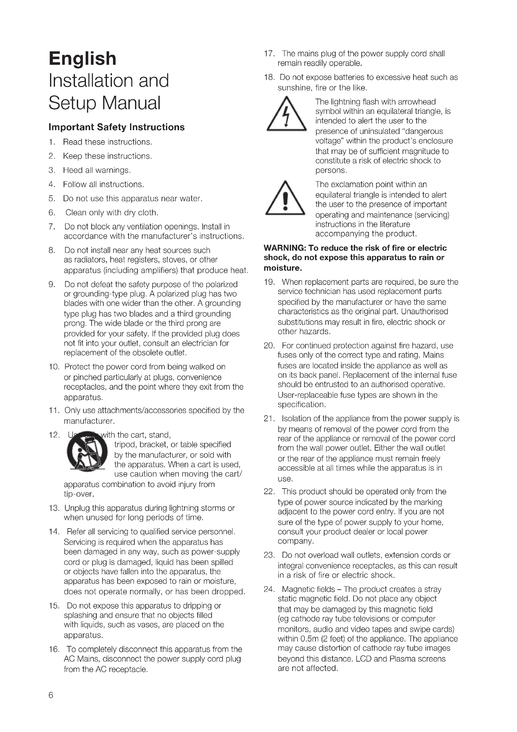
Ensure the wall studding is properly prepared so that there is sufficient clearance for the Back Box and its cable entry gland. The Back Box is intended to fit between two adjacent wall studs (battens) on standard 40cm (16 in) spacing. A cross brace (a noggin) should be positioned directly above the subwoofer. The subwoofer driver aperture should be located at the bottom. See Figure 1.
To begin installing the Back Box, loosen the six M5 bolts enough so that the brackets can be adjusted. Position the right-angle ends of the brackets outboard of the sides of the Back Box so that they are in position to line-up with the inside surface of the wall studs. See Figure 2.
Once the brackets are secured to the Back Box it can be fitted in the wall. Position the Back Box in the wall and screw or nail the brackets to the wall studs. Use a spirit level to ensure the box is vertical in both planes and tighten the bolts securing brackets to the Back Box. See Figure 3.
Solid wall construction
If the ISW-4 is to be installed in a solid wall the Back Box should be built in to the brick or block-work in a similar manner to a window frame. The brackets, bolts and washers supplied with the Back Box will not be required. Care must be taken to avoid the Back Box rattling against the wall. It should therefore be wedged in position such as to provide a clear gap all round. If the Back Box is to be settled onto the lower course of bricks, use a flexible mastic rather than cement or mortar. Remember to leave clearance for the connection gland and cable. The Back Box is not designed to take the weight of the wall above, so a suitable lintel must be used. See Figure 4.
Stage 2: Routing the subwoofer cable
With the Back Box fitted in the wall, the cable from the SA250 amplifier can be routed through the wall and into the Back Box via its cable entry gland. Pull around 20cm (8 inches) of cable through the gland. Secure the cable so that it cannot rattle against the studding or drywall panels and tighten the gland around the cable. Apply gasket strip around the subwoofer hole in the back box. See Figure 5.
Stage 3: Plaster finishing the wall
In both drywall and solid wall installations the back box should be covered with sheetrock (plasterboard) followed by a plaster skim - on the back as well as the front if the wall is a single brick thickness. Sheetrock adjacent to the Back Box should always be fixed with generous beads of mastic to ensure that no audible vibration occurs.
The sheetrock that extends over the front of the Back Box must have a hole cut accurately to the necessary profile so that the Wall Frame can be subsequently fitted in place and secured. Apply the supplied gasket strip around the subwoofer hole in the back box. Apply sheetrock over the entire front of the Back Box securing it with a generous bead of mastic. Using a small sheetrock saw and, with the cutting template as a guide, cut out the aperture taking care not to damage the Back Box. Once the aperture has been cut the entire wall can be plaster skimmed. See Figure 6. Once the plaster is dry use a vacuum cleaner to remove completely any dust and debris from inside the Back Box.
Stage 4: Fitting the Wall Frame
The Wall Frame is secured to the Back Box using the "dog clamps" on its underside. Rotate the clamps so that they are oriented inwards and insert the Wall Frame into the Back Box so that the Wall Frame flange is flush with the plaster surface. When the Wall Frame is in position, tighten the dog clamp screws so that the frame is held securely and flat against the wall. Tighten opposite dog clamp screws in turn so that the Wall Frame is pulled flat on to the wall. Ensure that the connection cable within the Back Box has not been trapped as the Wall Frame dog clamps are tightened. See Figure 7.
The wall should be decorated at this stage, with the supplied Paint Mask fitted over the Back Box aperture. Use of the Paint Mask is especially important if spray or roller painting techniques are to be employed.
Stage 5: Fitting the Driver panel
With the Wall Frame secured and the wall decorated, the Driver Panel can be fitted. Strip 15mm of insulation from the connecting cable within the back box and connect it to the spring-loaded connection terminals on the rear of the Driver Panel. Take care to ensure that the connection polarity is correct. Connect the positive cable to the red terminal and the negative cable to the black terminal. Seat the Driver Panel within the Wall Frame and secure it with the six bolts supplied. Tighten opposite Driver Panel bolts in turn so that it is pulled flat into the Wall Frame. See Figure 8.
Once the Driver Panel is fitted the grille can be pushfitted in the slot between the panel and the Wall Frame. If the grille is to be painted, this should be done before it is fitted. The adhesive B&W badge supplied can be fitted to the grille if required. Take care to fit the badge symmetrically.
Stray Magnetic Fields
The subwoofer's drive units create stray magnetic fields that extend beyond its boundaries. We recommend you keep magnetically sensitive articles (CRT television and computer screens, computer discs, audio and video tapes, swipe cards and the like) at least 0.5m (20 in) from the speaker. LCD and plasma screens are not affected by magnetic fields.
Subwoofer Amplifier Installation
The SA250 subwoofer amplifier is intended to be installed in standard 19 inch equipment racks. It is
supplied with rack-mount ears but rack mount bolts and nuts are not supplied. Ensure that, once mounted in the rack, the amplifier is well ventilated and that its ventilation apertures are not obstructed. If the system is taken out of use for a long period, disconnect the subwoofer amplifier from the mains supply.
Rack Mounting the SA250
The SA250 is supplied with two rack mounting brackets for installation in standard equipment racks. To install these brackets: Install the rack mount bracket, inserting three of the small Philips head machine screws through the bracket and the threaded holes in the side of the amplifier. Repeat for the bracket on the other side of the amplifier.
SA250 Rack Handles
The rack mount brackets are supplied with handles, which can be installed or removed. The handles are installed with two of the long Philips head machine screws inserted through the rack mount bracket and into the threaded holes in the handles. If you do not use the handles, use the rubber hole plugs supplied with the bracket hardware to fill the exposed holes.
Subwoofer Amplifier Connections
The SA250 subwoofer amplifier is fitted with a variety of connection sockets on its rear panel:
1 x Mains input socket: Connect mains power using the appropriate cable for your territory.
1 x Neutrik Speakon Output Socket: A four-pole Speakon enabling connection of one or two (identical) subwoofoers. Speakon sockets provide a more secure and reliable connection than bare-wire or 4mm sockets.
4 x Binding Posts Outputs: Two pairs of binding posts provide alternative bare-wire or 4mm socket connection for one or two (identical) subwoofer.
1 x RCA Phono Input: Input socket for connection to an AV processor or preamplifier subwoofer output.
1 x XLR Input: Alternative balanced input socket for connection to an AV processor or preamplifier subwoofer output.
1 x RCA Phono Output: Output socket for connection to the input of a second subwoofer amplifier.
1 x XLR Output: Alternative balanced output socket for connection to the input of a second subwoofer amplifier.
2 x 3.5mm Jack Trigger Inputs: 12V trigger inputs to enable automated control of amplifier standby and movie/music function selection.
Connecting the subwoofer amplifier to the subwoofer, including the use of Speakon plugs, is covered in the Connecting Sections below.
Subwoofer Amplifier Controls
The SA250 subwoofer amplifier front panel carries the following controls.
Volume: Sets the overall volume of the subwoofer.
Filter: Sets the low-pass cut-off frequency of the subwoofer filter.
Low-pass In/Out: Engages or defeats the subwoofer filter.
Phase: Reverses the subwoofer output phase.
Bass Extension: Provides three bass extension options.
Movie/Music EQ: Provides equalisation options for music or movie programme material.
On/Auto/Standby: Provides switch-on and standby options.
Status Indicator: Illuminates to indicate the amplifier is switched on.
Fault Indicator: Illuminates to indicate a fault condition.
Connecting the Subwoofer Amplifier
All connections should be made with the equipment switched off.
The SA250 amplifier has two pairs of binding post connection terminals and one four-pole Neutrik Speakon connection socket on its rear panel. The binding post terminals provide quick and easy connection of stripped wires while Speakon sockets provide a more secure and reliable connection method. Two ISW-4 subwoofer can be connected to the amplifier through use of either the two pairs of binding posts or the supplied four-pole Speakon plug.
If the binding post terminals are to be used, connect the positive cable or cables to the red terminals and the negative cable or cables to the black terminals. Incorrect connection can result in poor imaging and loss of bass. Figure 9 illustrates the use of the binding post terminals to connect one or two subwoofer.
If the Speakon option is to be used, disassemble the Speakon plug as shown in Figure 10 connect the positive cable to the terminal marked +1 and the negative cable to the terminal marked -1. Terminals +2 and -2 are to be used when two subwoofoers are connected. Incorrect connection can result in poor imaging and loss of bass. Once the plug is reassembled it can be inserted into the socket and locked by twisting clockwise. Figure 11 illustrates the use of the Speakon plug to connect one or two subwoofoers.
Keep the total impedance of the speaker cable below the maximum recommended in the speaker specification. Use a low inductance cable.
Connect the signal input to the subwoofer amplifier using either the RCA phono or XLR options. A second subwoofer amplifier can be daisy-chained from the first by connecting to either the RCA phono or XLR output sockets.
Subwoofer Amplifier Setup and Control
Before Auditioning
Before auditioning the subwoofer installation and finetuning it, double check the connections. Make sure in particular that the phasing is correct. The positive terminals on the subwoofer (marked + and coloured
red) should be connected to the positive output terminals on the amplifier and the negative terminals on the subwoofer (marked - and coloured black) connected to the negative output terminals on the amplifier. Incorrect connection can result in a confused sound with poor bass.
Switching On and Off
The subwoofer amplifier is best switched on after any other items are switched off first. The On/Auto/ Standby and Status Indicator operate as follows:
On: With the switch set to "On", the subwoofer amplifier will remain fully active and the indicator will glow green.
Auto: With the switch set to "Auto", the subwoofer amplifier will initially become fully active and the indicator will glow green. After about 5 minutes without an input signal, the subwoofer amplifier will automatically enter "sleep" mode. The indicator will glow red. When an input signal is detected, the subwoofer amplifier will automatically become active and the indicator will glow green. The subwoofer amplifier will return to sleep after about 5 minutes with no input signal.
Audio-visual processors incorporating an "automatic" set up procedure may be "confused" by a subwoofer amplifier with an auto switch-on/sleep function. A potentially damaging fault condition can arise. The subwoofer amplifier is best left switched on and fully active during set up if such a processor is used.
Standby: With the switch set to "Standby" the subwoofer amplifier will become active when it receives an appropriate trigger signal via its 12V Trigger Input. Turning off the 12V signal will return the subwoofer amplifier to sleep. The indicator will glow green when the subwoofer amplifier is active and red when the subwoofer amplifier is in sleep.
Setting The Subwoofer Amplifier Controls
There are 6 controls to consider:
The VOLUME (LINE) control.
The LOW-PASS FREQUENCY control.
The LOW-PASS FILTER switch.
The BASS Extension switch.
The EQUALISATION.
The PHASE switch.
The appropriate settings depend on the equipment used with the subwoofer and the modes of connection. If using more than one subwoofer amplifier, ensure the controls on each one are set the same.
Home Theatre Settings
Set the VOLUME control initially to the 9 o'clock position.
Set the LOW-PASS FILTER switch to OFF.
Set the BASS EXTENSION switch initially to position A.
Set the PHASE switch initially to 0^
Setting the LOW-PASS FREQ setting is irrelevant as the filter is switched OUT.
Set the EQUALISATION switch to MOVIE.
See the "Fine Tuning" section for more.
The subwoofer and subwoofer amplifier are not a THX® licensed component, but may be used with a THX® controller if desired. If a THX® controller is used, ensure that the subwoofer function is enabled. This incorporates all the filtering and level setting required for the subwoofer in all modes. For level calibration, the internal test noise and channel level controls in the THX® controller should be used. In all cases the levels should be set to obtain 75dB SPL (C-weighted) at the listening position from the controller's internal noise test signal.
With other processors, configure the front and surround speakers to "large" or "small" as appropriate before setting the levels. Use the internal noise test signal and volume controls of the processor to set the levels of all the speakers. Only change the VOLUME control on the subwoofer amplifier if there is not enough range in the processor to achieve the correct levels. Inexpensive sound level meters are readily available from electronics stores and can be used to calibrate the levels. Refer to your processor manual for further details on how to set the levels.
2-channel Audio Settings
Set the VOLUME control initially to the 9 o'clock position.
Set the LOW-PASS FILTER switch to ON.
Set the BASS EXTENSION switch initially to position A.
Set the PHASE switch initially to 180^
Set the EQUALISATION switch to MUSIC.
Set the LOW-PASS FREQ control to match the -6dB low frequency cut-off frequency of the satellite speakers. Note: Both -3dB and -6dB figures can be found in the specification of each B&W speaker model. If the satellite speaker manufacturer quotes only a - 3dB frequency, the optimum setting for the LOW-PASS FREQ control should be between 0.6 and 0.9 times that figure. The more gradual the low frequency roll-off of the satellite speakers, the lower the frequency should be set.
See the Fine Tuning section for more.
Fine Tuning
Before fine tuning, make sure that all the connections in the installation are correct and secure.
Home Theatre
In home theatre systems, the subwoofer (LFE) signal is a separate channel rather than an extension of the signal to the satellite speakers. The LOW-PASS FILTER is switched off (or set to maximum), because the processor provides all the filtering for any speakers set to "small". However, the position of the PHASE switch must still be assessed. Normally the phase will be set to 0^ , but if the subwoofer is positioned at a distance significantly different from the other speakers, or the
power amplifier driving the other speakers happens to invert the signal, the 180^ position may be preferable. Listen with the switch in both positions and choose the one that gives the fullest sound. If there is little difference, leave the switch at 0^ .
Surround sound processors normally have a calibrated noise signal that can be used to set the relative levels of all the speakers, making the task somewhat more straightforward than for 2 channel audio. However, do not be afraid to alter the settings to your personal preference. It is all too easy to get carried away with the capabilities of the subwoofer, especially with some special low-frequency effects. Often a more realistic portrayal, and one more satisfying in the long term, is to be had by setting the subwoofer level lower than the standard calibration level.
2-channel Audio
Set the system up in the preferred position and play some material with a steady bass content.
The optimum settings of the PHASE switch and the LOW-PASS FREQ control are inter-related and also dependent on the low-frequency cut-off characteristic of the satellite speakers. However, the settings recommended above for the LOW PASS FREQ control and PHASE switch have been chosen to integrate well with most satellite speaker bass alignments.
Using the initial settings, first check the setting of the PHASE switch. Choose the option that gives the fullest sound. Normally the recommended option will be optimum, but may not be in certain circumstances. These may be that the power amplifiers feeding the satellite speakers invert the signal or that the subwoofer is not placed close to the satellite speakers.
Next, adjust the VOLUME of the subwoofer amplifier relative to the satellite systems to your liking. Use a wide variety of programme material to get an average setting. A setting that sounds impressive on one piece may sound overpowering on another. Listen at a realistic volume level as the perception of musical balance varies with sound level.
Finally, adjust the LOW-PASS FREQ control to give the smoothest transition between the subwoofer and satellite speakers.
All Applications
The BASS EXTENSION switch offers three options of subwoofer bass extension. Position A gives the greatest extension and position C gives the least extension. Position B provides a compromise setting. If the system is to be used at very high volume levels or in a large listening room, restricting the bass extension by selecting either B or C may help ensure that the subwoofer is not asked to exceed its performance limits. In most situations the BASS EXTENSION switch should be left in position A.
The EQUALISATION switch alters the subwoofer bass roll-off alignment appropriate to MOVIE or MUSIC listening. The MOVIE position gives a "drier" alignment, more suited to the demands of action movie low frequency effects. The MUSIC position is suited to a faster more accurate bass line. The 3.5mm Equalisation input on the back panel is designed to
receive a 12V signal that will toggle the MOVIE/MUSIC setting at the front panel. Set appropriately, the 12V trigger output of a processor can automate ideal performance of the subwoofer. If the front panel switch is set for MOVIE, the 12V trigger will change it to MUSIC. The reverse is also true. Care must be taken in setup of the processor in order to take advantage of this feature.
Running-in Period
The performance of the speaker will change subtly during the initial listening period. If the speaker has been stored in a cold environment, the damping compounds and suspension materials of the drive units will take some time to recover their correct mechanical properties. The drive unit suspensions will also loosen up during the first hours of use. The time taken for the speaker to achieve its intended performance will vary depending on previous storage conditions and how it is used. As a guide, allow up to a week for the temperature effects to stabilise and 15 hours of average use for the mechanical parts to attain their intended design characteristics.
However, longer run-in periods (as long as a month) have been reported and there is evidence to suggest that this has little to do with the speaker changing and more to do with the listener getting used to the new sound. This is especially so with highly revealing speakers such as these where there may be a significant increase in the amount of detail compared with what the listener has previously been used to; the sound may at first appear too "up front" and perhaps a little hard. After an extended period of time the sound will seem to mellow, but without losing clarity and detail.
Neutrik® and the names of Neutrik® products referenced herein are either trademarks and/or service marks of Neutrik®.
Limited Warranty
This product has been designed and manufactured to the highest quality standards. However, if something does go wrong with this product, B&W Group Ltd. and its national distributors warrant free of charge labour (exclusion may apply) and replacement parts in any country served by an official B&W distributor.
This limited warranty is valid for a period of five years from the date of purchase or two years for electronics including amplified loudspeakers.
Terms and Conditions
1 The warranty is limited to the repair of the equipment. Neither transportation, nor any other costs, nor any risk for removal, transportation and installation of products is covered by this warranty.
2 This warranty is only valid for the original owner. It is not transferable.
3 This warranty will not be applicable in cases other than defects in materials and/or workmanship at the time of purchase and will not be applicable:
a. for damages caused by incorrect installation, connection or packing,
b. for damages caused by any use other than correct use described in the user manual, negligence, modifications, or use of parts that are not made or authorised by B&W,
c. for damages caused by faulty or unsuitable ancillary equipment,
d. for damages caused by accidents, lightning, water, fire heat, war, public disturbances or any other cause beyond the reasonable control of B&W and its appointed distributors,
e. for products whose serial number has been altered, deleted, removed or made illegible,
f. if repairs or modifications have been executed by an unauthorised person.
4 This guarantee complements any national/regional law obligations of dealers or national distributors and does not affect your statutory rights as a customer.
How to claim repairs under warranty
Should service be required, please follow the following procedure:
1 If the equipment is being used in the country of purchase, you should contact the B&W authorised dealer from whom the equipment was purchased.
2 If the equipment is being used outside the country of purchase, you should contact the B&W national distributor in the country of residence who will advise where the equipment can be serviced. You can call B&W in the UK or visit our web site to get the contact details of your local distributor.
To validate your warranty, you will need to produce the warranty booklet completed and stamped by your dealer on the date of purchase. Alternatively, you will need the original sales invoice or other proof of ownership and date of purchase.
EI control LOW-PASS FREQUENCY.
EI conmutador LOW-PASS FILTER.
EI control EQUALISATION.
Parimetros Home Theatre
He noDBepraIte H3dJIne BO3dIeCTBnIO DOxJH, He NCNoJIb3yIte 3TO H3dJIe N6BIuN BODbl, a TaKXe B YcNOBHX IOBblIeHHoB BlaXHOCTN, He CTaBbTe npEdMeTbI, HAnOJIHeHHbIe XnIDKOCTbIO, HApPmep Ba3bl, Ha yCTpoIcTBO, YTObI BHyTpB He nonana XnIDKOCTb.
Pn yctaHOBe ycTpoNCTBa y6eDNTecb,TO po3eTKa, IINo pa3bEm C3aDN BcERda OCTaeTcA JeKo DoCTyHbIM BO BpeM pa60Tbl.
EcnB03HnKna HncnpaBHOCTb, HemeJeHHOBbIKIOHTe CeTeBOe NITaHne N BbIHbTe BNKyUCTPOIcTBa n3 pO3eTKN.
JaXe KOrDa CeTeBOE NITaHne OTKJIIOUeHO TlaBHBIM BbIKIOuHaTeJeM, 3NEKTPnueCTBO npoDOnJxaeT NOCTyNaTb B yCTpoIcTB HO HA MINHMaJIbHOM yPOBHe. EcnB He CO6HpaeTeCb nCNoJIb3ObA Tb 3TO yCTpOcTBo B TeueHne DInTEbHOrO BpeMeHn, BblHbTe CeTeByIO BuNKy U3 po3ETKn.
BVeJeHne
Ybaxaembl nOKyNaTeJIb,
Cnacn6o, yTO BbI BbIbpaN Bowers & Wilkins.
PoxkanyuCTa, npOHTte 3Ty UHcTpyKuHIO
BHMATEJIbHO npeD paCnakOBKO uYcTaHOBKO
npOdyKTa. 3TO NOMOKeT Bam ONTmU3npoBaT b erO
XapaKTepNCtIKN.
B&W meeT ceTb cneuaHn3npoBaHHbIX DnCTprnbIOTOPOB 60JIe, Yem B 60 CTpaHax, n OHN CMORYT NOMOy Bam npu BO3HKnHOBeHN JIO6bIX Pno6JIeM, C KOToPbIMn He CnpaBUNICb DnJIepbl.
Hhopmaunno 3auntte okpykaoue Cpebl


PpOdykTbI B&W Co3daHbI B NOJHOM COOTBETCTBm C MEXkyHaOpDHBIM INPeKtUBaMn IO ORpaHnueHnM
nCnoB3OBAHnOnacbIX MaTePnaJIOB (Restriction of Hazardous Substances - RoHS) B 3NeKtpnueckom n 3NeKtpoHOM obOpydoBaHn, a TaKxe no er0 yTnIImaunn (Waste Electrical and Electronic Equipment - WEEE). 3NaK nepepepkHyTorO MycOpHOro 6aka O3Haayet COOTBeTCTBVe DInpeKtNBam IN To, YTO npOdyKT DOJKeH 6blTb npaBnBHO yTnIIm3OBaH nIN nepepa6Otah.
IpOKoHcyJbTnpUyTeCb C BaWe MeCTHOJ opraHn3aUnnei, KOToPAJ 3aHIMaeTcY yTuIN3aUnnei OTXODOB, NO BOpocam npaBnBHOJ cDaUNBaWero O6OpyDoBaHHA B yTuNb.
B 3ToHnHCTpyKcun OnncaH BCTpaNBAeMbI B CTehb caByep ISW-4, ero TBInOBaR Kopo6ka n corlacoBaHHb C Hm yCnJIteJIb MoUHocTn SA250, MOHTnpyEmbI B CToiKy.
CoepeXnMoE ynaKOBKn
IpoDyKT NOCTaBnEeTcB TpEx Kopo6kax: ynaKOBka ISW-4, ynaKOBka c TbIOBOH Kopo6kOu NKopo6ka C ycuiNTeJem SA250.
Kpome nahenC dHnHAMNKOM, B ynaKOBKe ISW-4 DOJXHBi HxOAnTbcra:
3Ta INHCTpyKUIN
1 x pama dny yctahOBKn BCTeHy
1x3aunTHaepweTka(rpnJb)
1xwa6noHdny npoemaBCTeHe
1xIorotnB&WHaJinyuKe
1xMaCKaIyNOKpackn
6xM560JTOB
Kpome camoTbIOBOI Kopo6Kn,BynaKOBKe IJI Hee DOnXHbI HaxOuTbCra:
1xHCTpyKUINoYcTaHOBKe
1xpylonynpntela
Kpome camoro ycnntena SA250,Bynakobke nna Hero donxkhbl HaxoNTbcra:
1XcTeB0Ka6eJb
1 x ueTbipexnIOIochbl pa3bem Neutrik Speakon
2xcko6blnMOHTaXaBcToiKypeK)
6X KOPOTKnx BNHTOB C WIECTNIRpaHHbIMN FOJIOBKAmN uwaib
4xpe3nHOBbix 3arnywek DnO TBepctn
2xpyuKn
4xDINHHbIX BNHTOB C 8eCTnIgpaHHbIMN FOJIOBkAMn uwa6
Ca6ByΦep ISW-4 cKoHCTpyuropOBaH dIy INHCTaJIaCIMDOMaUHrO TeaTpa, a TaKKe dIy NOkPpeNHeHb6acOBbIX COCTaBIAIOx "NOHDoNAa3OHbIX" KOHOK B 2-KaHaJIbHbIX ayDNo CnCTeMax. IIO6aaydno IHCTaJIaCIN Tpe6by TPOdymaHORO IOxOda, yTO6bl paKpbItb BeCb NOTeHcuaJ TeXnKn,
I 3Ta IINCTpyKcIy NMOXeT Bam I HAppaBNT B XOde BCero Ipocecca.
Ca6ByfepHbI yCnnteB SA250 Tpe6yeT NOcOeINHeHnK 3JIeKTPocETn, nO3ToMy BaXHo, YTO6bl Bbl N3yUHn INCTpyKuIN No 6e3oNaChOCTn I CO6JIIOaJI N BCE ppeOCTepExEHH. XpaHITe 3TO pyKOBOCTBO B HaJeKHOM MeCTe DnIPOJyEHnR CNpABOK B 6yDyUeM.
Pa3meuenec6Byepa
Haun yun nloxo uYBCTBYOT HanpaBHeHne Ha nctOuHHK Hn3Knx 3ByKObblx YactOT, TaK UTo pa3Meune Ca6BypepoB B KOMHaTe npocnyuBaHn OobIyHO Mehee KpNTuHO, cem IJNoHODnana3OHbIX KOLOHOK. Tem He Mehee, ROBOPAT, TTO HanLyUWe pe3yIbTaTbI ObluHO DOCTnraOTc, ecnn ca6Bypep pacNOJoxeH MEXdY npaBoi N JeBoi CpOHTaJIbHbIMN KOONKaMn, INI NObIN3OCTN OT ONDH N3 HNX. Ecnn NCOnOB3yOTc IBa ca6Byepa, Lyuwe BCero ODNH NOCTaBtB PAnOM CJeBoi KOONKoA, a Dpyro - C npaBOi.
Pa3MeHne ca6Bycpepa B Ondno 60KOBbIX CTEN KOMHaTb npocnyuBaHn, npueem daXe I03aMn MeCTa npocnyuBaHn, TaKKe BO3MOxHO, HO 06bIHO 3TO npINBOJNT K UxydUeHnO 3BYKOBOrO 6pa3a. Ondako 3TO MOxET CTAb npneMJIeMbIM KOMnpOMuCCOM, OCO6eHNO B MHOROKAHaJIbHbIX AV CNCTeMaX, IDe pa3MeHne DInkTyIOT YCIOBnB INOME.
Tak je, KaK i DnB Bcex Dpynx KOJIOHOK, 6JN3OCTb rpaHnC KOMHaTb CInbHO BInaReT Ha 3ByuHaHe caBvepa. IpomKocTb 6aca Bo3pactaet no Mepe TORo, KaK CTeHbI CTAHOBRTc 6bnXe K caBvepy. OJnako, B OTJIuHne OT NOnHOdna30HbIX KOJOhok, 6UIN TOHaJIbHbI 6aNaHC CuCTembl MOxHo NOkOppeKtnpOBaTb C NOMOUsbPOperyJrTOpa rpoMkoCTn CaBvepa. Yem 6OJIbWe 3ΦΦeKT OT rpaHnC KOMHaTbI, TEM MeHbWe DOJXHa 6bITb BBICTaBNeHa rPOMKOCTb, IN TEM JERYe CaBvepy pa6OtaTB; OJnako TYT ECTb IN O6OpOTHa nCTopoHa. CaBvepbI, pa3MeueHHbIe 6JIn3KO K yRJaam, YaCTO reHepnPuyOT 6OJIbWe Hn3KoAcTOTHbIX pe3OHaHCOB B KOMHaTe, DeJa 6ac eJe 6OJee HepaBHomepHbIM NO qACTOTE.
IcnoJIb3OBAHHe MHOrN Ca6ByepeOB B OdHOINHCTaJIaCm MOKeT yJyUHTb KaueCTBO 3ByaHnHECKoJIbKIMn CnocO6aMn:
- ПодержаТь pa3дeл徳е Cтpeо KaHaNoB Ha caMbIX Hn3Knx YacToTax.
- CrnaIbTB BnHHe Hn3KoAcToTHbIX pe3OHaHCOB NOMEueHnA.
I03BOJNT NOBbICITb MaKcIMaJIbHOe 3ByKOBOE daBneHHe.
EcnI DbCa6BypepaNCnOJb3yOTcB2-KaHaJIbHO ayDIO CnCTeMe, CTepeo pa3deneHne 6yDeT yNyUHeHO TOnbKO B TOM Cnyue, KOrDa KaKDbI KaHaI NMeET CBOI CO6CTBeHHbI Ca6Bypep, pa3MeUeHHbI IO6JI3OCTN OT COOTBETCTBYIOSei CaTeJIINTHOJ KOJOHKN.
YcTaHOBka ca6Bypepa
BCTpanBaembim ca6bypep ISW-4 npedHa3haueHДЯ INHCTaJIaIcIM B HObIe rINCOkAPTOHHbIe CTeHbI (KapKacHbIe, C neperopOkaMn) nIN B KaNTaJIbHbIe CTeHbI (KupNCHbIe nIN JeKeIe3oBeToHHbIe).B 06Onx CnyuHx INCTaJIaIcIM DOJXHa 6blb HaYATAdo TORO, KaK WtYKaTYPka n/nnr TnCOkAPTOHHbIe JNCTbI HaHeceHbI Ha CTeHy. MoXHO TaXKe yCTaHOBtB ca6BypeP B cyUeCTByIOUyIO rINCOkAPTOHHyIO CTeHy, HO O6bEm pa6Ot no nepeCtpoKe MOXET CDeNaTb TaKoe peWeHne HEnpaKTNUHbIM.
TuaTeIbHO paccMOptnTE nocNeIDCTBnY yCTaHOBKn B cyueCTByIOUyIO CTeHy, npexKe Yem npucTyNaTb K pa6oTe. TblOBaH Kopo6Ka (Back Box), NOCTaBnHaMaB BmecTe c ISW-4, 3aJaET dNHe Hero akCyteckyH Harpy3K u 6n3aTeNbHO DOnkHa 6bITb NcNoJIb3OBAHa dNn OBeCneueHn erOp naBnHo pa60TbI.
3tan 1: IoproHka no MecTy tblIOBOI Kopo6Kn
TnncokapToHHbIe CTeHbI (KapKaChbIe, c neperopokamn)
Y6eIntecb, yTO neperopoKn obecneuBAIO TocTaTOUHO MeCTa DnTbIIOBOI Kopo6Kn I dN PyKaBa, B KOTOpOM 6yDet npOnyuCeH Ka6en. TbIOBAA Kopo6ka paccHTaHa Ha To, YTO6bl yMeCTNTBCM MEXDy DByM COCEHNMI neperopoKAMn (nonepueHHbIM peHKAM), O6bIHPO paCNOLOXKeHHbIM Ha CTaHdApTHOM pacCTOHN 40 cm (16 in). NonepeuHa paCnpOPka (DOCKa) DOJXHa 6bITb paCNOLOXeHa nPMAO HAd ca6ByΦepOM. OTBepCTne dIra DNHaMKa ca6ByΦepa DoJXHo 6bITb cH3y. Cm. Figure 1.
YTO6bHaayaTb yCTaHOBky TBINOBOK KOPo6Kn, Ocna6bTe Wectb 6oNTOB M5,Tak YTO6bIMoXHO 6bIIO NoOOrHaTb CkO6bl NMeCy.BiDINbTe npabBe KOHcbl CKo6 HApxKy n3 TbIOBOK KOp6Kn TaK,YTO6bl OHn COBmecTnncb C BHyTpHeHne NOBepxHOCTbIO neperopOdoK bCTeHe.CM Figure 2.
Kak TOnbKO cKo6bI 3aKpeNJIeHb I TBIOBOI Kopo6Ke, INx MoXHO 3aΦNKcHPOBaTb Ha CTHe. YCTaHOBNTe TBIOBYO Kopo6Ky B CTHe N pPikpeNITe ee WypynAmn ININ rBO3dAMN K CTeHHbIM NpeEROpOdkam. INcNoJb3yUte CnIPTOB0YpOBeH dInr OecneueHnBepTKKaJbHO rO paCNOLOXeHn Kopo6Kn B OBeNX PINOCKOCTHX 3aTeM 3aTAHHTe 60NTbl, KpeNJIue CKo6bHa TBIOBOI Kopo6Ke.CM.Figure 3.
Jyue BCero BKIOaTb ca6BypepHbYcNJITeIb NocIe BCEX OCTaHBbIX KOMHOHETOB, a BblKIOUaTb nepBBIM. INdkaTopb BYKIOUeHn On/Auto/Standby n COCTOHN Status pa6oTaOT cJeDyUOIm o6pa30M:
On: npn nepeKIOUOaTeNe B NOJoxeHm "On", ca6ByoepHbI yCNIHTeNb 6yDet OCTaBaTbcr NONHOCTbO aKTINBbIM IN HdNKaTOP 6yDet CBETNTcR 3eJIeHbIM.
Auto: npn nepeKlIOuATENe B noLoXeHnn "Auto", ca6BypehBiy ycInIteB 6yDet cHaana noNHOCTbO aKTNBbIM n INDkATOp 6yDet CBETNTCBs3eHbIM. Nocne 5 MInHT 6e3 BXoDHoro CnHa,ca6BypehBiy ycInIteB aTOMaTHueCKn nepeJTeB CnAun peXm ("sleep"). INDkATOp 6yDet CBETNTCB KpacHBIM. Pn o6HApXeHn CnHaHa HbxOJe, ca6BypehBiy ycInIteB aTOMaTHueCKn nepeJDet B aKTNBbI pyekM, n INDkATOp 6yDet CBETNTCB 3eHbIM. Ca6BypehBiy ycInIteB BEpHETC B CnAun peXm NOcne 5 MInHTOTCYTCTBn BxODHOrO CnHaJa.
AV-npoecccopb c aBTOMaTHuecko npoceDpyo nactpoKMOrT 6bITb "03aDaueHb" cyHKcneB abTO-OTKnIOUeHnca6Bypepa (switch-on/sleep). MoKeT DaXe Bo3HNKHyTb NToEHuaNbHO onaChnacnTyauu nOTKa3a. JyUwe Bcero BO Bpem npoceCa nactpoKn nepeBeCTn ca6Bypehbl yCINNTeB B peXIM IONHO AKTUBHOCTn, ecIn Y Bac B CnCTeme nCNOlb3yETc TaKoN pnoeccop.
Standby: npn nepeknioatele B noIooKeHH "Standby" ca6ByeepHbI ycNInTeJIb 6yJeT aKTHBbIM, KOrda nOlyuHT TpIRrRePbI CNHaI +12 B ha cBoi BXoJ 12V Trigger. OTKIOueHne 3TorO cnHaIa BepHeT ca6ByeepHbI ycNInTeJIb B CnAun peXIM. INdNKaTOP 6yDeT CBETNbC3EJIbIM, KOrda ca6ByeepHbI ycNInTeJIb aKTHBeH N KpaChbIM, KOrda OH B cnaeM peXIME..
HactpoJa ca6Bypephoro ycnJnteJc nOMOuOpraHOB ynpaBHeHn
Bcero nmeetc6 perynipobok:
VOLUME (LINE) - rpoMkoctb.
LOW-PASS FREQUENCY - yacToTa cpe3a.
LOW-PASS FILTER -nepeKnIouaTeNb 0nIbTpa.
BASS Extension - nepeknlouateIb paacnpeHna 6acob.
EQUALISATION -əkbaaɪəep.
PHASE -nepekIIOuataTeIb a3bl
NoJoxHepeRyIupOBK3aBnCITOTobOpyIOBaHn, nCnoJIb3yEmoB Bmecte C caBBycpepom n OT xapaKTepa noKluOeHn. EcnBblncnoJIb3yeTe 60nee Ondoro caBBycpehoro ycInnten, yBeDNTecb, YTO HnX BbICTaBJeHbOINHaKObIe napameTpbl.
HactpoKa DomaHero TeaTpa
YCTAHOBITE peryJITOP VOLUME cchaJaBA B NOJOXHeH "9 YacOB".
YcTaHOBnTe nepeKIOuOaTeIb LOW-PASS FILTER B noLoXeHne OFF (BbIKIOUeH).
YcTaHOBInTe InHaHauAna nepeKIOUaTeJIb BASS EXTENSION B noJIOXeHne A.
YctaHOBNTe InHaHauJaI nepeKIOUaTeIb PHASE B NOLOXKeHne 0^
ПОJOKEHNE LOW-PASS FREQ He IMeET 3HaueHnR, T.K.ФИЛТР OTKIQUeH - OUT.
YcTaHOBInTe nepeKIOuAteIb EQUALISATION B NOJOKeHne MOVIE.
CM. TaKxe pa3dEn "ToHaa HacTpoKa" - "Fine Tuning" dJa 6oJee noDpO6Ho nHΦopMaun.
Ca6ByΦepbI n ca6ByΦepHbI yCnJIteJIb He
RBAJOTcA LIueH3NpOBaHHbIMN KOMNoHEHTAMN THX, Ho, npu JeHaHN, MOrY T 6blT NcNoJIb3OBAHbI
c KOHTpOJIePOM THX. EcIn nCnoJIb3YeTCr THX controller, npoBepTe, BkJIouHeHa Jn φyHKUra
ca6ByΦepa.
3TO o6cneHT BCIO Heo6xOIMMyO fNJIbTpaUIO uYCTAHOBky yPOBHei, Heo6xOIMbIX dIra ca6Bypepa BO BCEX pEXImax.ДЯ KAIIN6P0BKN yPOBHei HEo6xOIMMO IcNoIb3OBaTB BHyTpEHHI rHepaTop TecTOBOrO 7yMa n NOKaHaNbHbIe perynipOBKn yPOBHei, IMeIoUneCBA THX KOHTpOJInepe.Bo BCEX CnyaJx yPOBHN DOnKHBi 6bITb BbICTaBNeHbI TaK, YTo6bl NOnyUHTb 3ByKOBoE daBJIeHne 75 dS (SPL) (C-B3BeWeHHOe) Ha MeCTe dIra npocLyuBaHnC NOMOJIbco6CTBeHHORO 7yMoBOrO TECT-CnIHAna KOHTpOJIpepa.
Pn nCnoB3ObaHn dpyrnx npoecccopOB, nepeD yCTaHOBKO yPOBHe 3aDaBaTe ppoHTaNbHbIe N OKpyKaIOUne KOLOHKn KaK "large" nn "small" - B COOTBETCTBN C INX BO3MOxHOCCTAMN. IcNoJb3yInTe BHyTpeHHN TECT-CnHaN n perylnpOBKn rPoMKoCTn npoecccopa DnA 3aDaHn yPOBHe rPoMKoCTn KOnOHk. MeHnTe yCTaHOBky VOLUME Ha ca6BypeHOM ycINTEne TOJIbKO B TOM CInyae, ecnn y npocccopa He XbTaet WInPNbI dNaNa3OHa dJa DoCTNXeHn npabINbHbIX yPOBHe. HeOporne n3MepNTeHN yPOBn (3ByKOBO DaBJeHn) MOxHO JERKO KynITb B Mara3INhax 3NeKTPOHnKn HNCNoB3OBAtB DnA KaINbPobKn. CMOTpnte IHCTpyKUnO Ha BaW npocccop Dn A NOUYehn
6oJee noIpO6HoHnHΦopMauN nO hAcTpoKe yPOBHei.
HactpoKa 2-KaHaJIbHoI aydNo cncTeMbI
YcTaHOBnTe cHaJaIa peryJrTOp VOLUME B nOIOKeHne "9 YacOB".
YcTaHOBnTe nepeKJIIOuHaTeIb LOW-PASS FILTER B noJoxHeNE ON (BKnHoueH).
YcTaHOBInTe dIHaHauana nepeKIOuOaTeJIb BASS EXTENSION B noLoXKeHne A.
YcTaHOBInTe nepeKInouaTeInb EQUALISATION b noLoXeHne MUSIC.
YcTaHOBInTe nIaHaJa nepeKIOUaTeJIb PHASE B noLoXeHne 180^
YcTaHOBtTe YacToTy Cpe3a LOW-PASS FREQ TaK, TTO6bI corNaCoBaTb cnaI -6dB Ha Hei C HnXHei rpaHnuei XapaKTepeNtIK CaTeJIInTHbIX KOLOHOK. IpImeHaHne: B cneUPhiKaunx Ha KOLOHKn B&W MOxHo HaTIu cndpbk KaK Ha ypoBHe -3dB, TaK n -6dB .Ecnn npOn3BODntTe b CeTeJIInTHbIX KOLOHOK npINBOIDNT B NaCnOpTe HnXHIOU YacToTy ToJIbKO Ha ypoBHe - 3dB, TO ONTMaJIbHaar YcTaHOBka dIy perynipOBKn LOW-PASS FREQ DoJnxHa 6bITb rDe-To MExdy 0.6 n 0.9 OT eTOn BeJIuHnbl. Yem 6Olee PJIaBbI CNaI qAcToTHoXapaKTepeNCTNK U caTEJIInTHbIX KOLOHOK, TEM HNXe HxKHO BblPaTb YacToTy Cpe3a.
Cm. TaKke pa3den "ToUH aHcTpoIka" - "Fine Tuning"ДЯ 6OJIe NOdpo6HOn INΦopMaun.
ToHnHa HacTpoNka
Ipeed ToHn HAcToHKn y6eDntecb, YTO BCE COeHNHeNn B BaWei nHCTaJIauu CdeNaHbI npabNbHO n 6e3OnaCHO.
DomaHnTeaTp
B cncTeMax domaunHero TeaTpa nocTynaIoUmHa ca6Bycpe cnHn3KoYAcTbHbIX 3ΦΦeKTOB (LFE) npedctabnreT c608 otDeIbHbI KaHAn, a He npoJOnJxHe nCnHa, noDaBaEMO Ha caTeJIInTHbIe KOJOnKn. Hc nIbTp LOW-PASS FILTER doJxen 6bItb BvIKNoUeyen (nn yCTaHOBNeH Ha MaKcIMyM), TAK KApocccop oecneuBaET BCIO pNltpauIO IJIIO6bIX KOJOnOHK, OxapakTePn3OBaHHbIX KaK "MaIbe" ("small"). Ondako, heo6xoDmO o6paNTb BHImaHne Ha noJoxKeHne nepeKlIOuAteTEn Pa3bl PHASE. O6bHuO pa3a yCTaHaBnBaETcHn Oo, Ho ecnI ca6Bypep pacnoJoxKeH Ha ropa3do BoNbseM pacCToHNOT CnywateTEn, Yem DpyrVe KOJOnKn, IINec yCnIInTeB MOsHOCtN, NITaIOuN dpyrVe KOJOnKn, INHBepTnpyET CnHaN, To noJoxKeHne 180 MoXeT OKa3aTbcn PpeIDNoUTnteBHe. IpOn3BeDnTe npocnyuBaHne C nepeKlIOuAteTEm B o6Oux IonoJoxHenx n Bbl6epnTe TO, KOTOpoe oecneuBaet Hanbolee HacblueHoe 3ByaHne. Ecn pa3Nuca Heoblbwa, OCTabbTe nepeKlIOuAteTb B noJoxEHN 0°.
O6bHNO npoecccopbl okpykaIoUeero 3Byka
IMMeIOT TcTeOBbl rHePaTOp KaINbPoBaHHoro
yMBOrO CNHaJa, nCNoB3yeMbI DnY yCTaHOBKn
OTHCnTeNbHbIX ypOBHe rPOMKocTN BCex
KOLOHOK,TOO6JIeYaeHAcTPOkyCnCTEmblDOMaUHrero KINHOTeaTp aNo cpaBHeHIO CDByXKaHaJIbHoayDIOOCnCTEmo.ODHako, He60IteCb MeHb HAcTPOky B COOTBeTCTBmNCBaUM BKyCOM.Pn3TOM, npabda, ouehbJeKOByBneCyBO3MOxHOCTaMn Ca6Bypepa,OcObeHNO CNEuΦnueCKMn Hn3KoUacToTHbIMN 3ΦΦeKTAMN.Ho BCEJHe,HaIbOone peAInCTuHoe n,B KOHeuHOM ITORE,HaImeHee YTOmTEJBHOe 3ByaHne YaCTO DoCTnraEaTCyTaHOBKO yPoBnCa6Bypepa HxKe,Yem CTaHapThbI yPoBEh KaINbPbKN.
2-kaHaJIbHaI ayDnO cnCTema
PacCTaBBTe BcO CnCTeMy B Han6oJIee
npEINOHTeBHom NOJoxeHm IN pOcNywaIte
HeCKoJIbKO My3bIKAJIbHBIX nporpaMM C NOCTOHHOHN
6acOBoCocTAbNIOUWe. ONTMaJIbHbIE yCTaHOBKn
nepeKIOuATeNA PHASE n peryIaTopa LOWPASS FILTER B3aIMOCBraHbI N, NOMMO 3TORO,
3aBNCrOT napamETPOB cnaDa Ha HN3KNX
Yactotax xapaKTepnCTIK caTeJIINTOB. Tem He
Mehee, peKOMeHDoBAHHbIE Bblwe yCTaHOBKn
PHASE I LOW-PASS FILTER 6bln Bbl6paHbI dJa
XopoWei INTerpaun C 6acOBbIMN BO3MOxHOCTAMN
60JIbUnHCTBa caTeJIINTOB.
IcnoJb3y npBHOaHbHbIe yCTaHOBKn, CHaHaI npOBepbTe NOLOXeHne nepeKIOUaTeTn pa3bI PHASE. Bb6epnte To, KOtOpoe oEoceuHbaet Hanbolee noHOBecHoe 3ByaHne. ObHuHO peKOMeHNoBaHHoe nOLOXeHne OKa3bIBaETc ONTMaJIbHbIM, HO IHOrJa 3TO MOKeT 6blr He TaK. HanpImep, ecn yCUNITn MOuHocTn, nTuAQUHe caTeJIINrbl, INHBepTyIOT CnHaI; IIn ecn ca6ByΦepbl pacNoJIOXeHbl DaNEKO OT cATEJIINTOB.
Iocne 3TOrO yCTaHOBnTe rPOMKoCTb VOLUME ca6ByΦepHoro ycINITeJI NO OTHOWeHIO K caTeJIITam B 3aBNCIMOCtN OT JNUHORo BKyCa.ДЯ Bbl6paYcpeDHeHNO BapnaHTa, npocnyuaiTe pa3Hoo6pa3HbIe My3bIkaJIbHbIe npOn3BeDeHn. To, YTO BNeUaTJAEr Ha ODHOM MaTePnAne, MoXET nOKa3aTbCRA CNIuWKOM MOuHbIM DnA DpyrOro. BocpnaTne 6aHaHca Toxke 3aBNCIT OT yPOBnR rPOMKoCTn, N0TOMy npOn3BOdnte npocnyuBaHnE Ha pa3ymHOr rPOMKOCTn.
HaKoHeu, BbIePeNTe YacToTy peryJrTopom LOWPASS FILTER TaK, YTO6bl CTbIKOBKa xapaKTePnCTNKcaBBypepa n caTeJIITOB 6bla MaKcIMaJIbHoIIaBHOI.
ДлЯ BCex CnTyaun
IpeeknOuateB BASS EXTENSION npednaeraT prn BapnHaTa pacwnpeHn8 bacOB. IonoXeHne A daet camoe cnbHoe pacwnpeHne, a C - HauMeHbuee. IonoXeHne B oecneuHbaet KOMnpomccHyo yctahOBky. Ecnn CnCTema 6yDet NcNoB30BaTbcra Ha OOhb BblCOKnx ypoBHX rPOMKoCTn nnB 6oNbWOM NOMeUeHN, orpaHnueHne pacwnpeHn8 bacOB BB6opom B nC moKeT NmOuy Bam y6eDnTbcra, YTO OT ca6Byepepa He Tpe6yeTc8 BbiTn 3a npedeJI erO BO3MOxHOCTei. OdHaKO B 6oNbWInHCTBe cntyaun peeknOuatoB BASS EXTENSION DOnJKeH 6bITb OCTabJeH B IonoXeHN A.
IpeekJIuOaTeIb YacToTHoK KoppeKcH IN EQUALISATION n3MeHReT BnD Hc cnaDa XapaKTepnCTnK Ca6ByepeHaNoXoJaun Dnpa
peKIma MOVIE nnMUSIC. NoJoxeHne MOVIE Daet 6oJee CnepKaHHoe, "CyxoE" 3BvuaHne N LyUwe pa6Otae npu yrnoBom pa3MeueHnCa6Byepea nnB rYknO KOMHaTe. NoJoxeHne MUSIC 60nbue NOxODNT dnn "rIyXoN" KOMHaTbI n pa3MeueHn Ca6ByepeBaIOnyOT yra-OHO oBeceHnBaET 6oJee 6bICTpbI n YeTKN bAcOBbl OTKnK.
Pa3bem 3.5-MM c Ha3BaHnEM EQUALISATION Ha 3aJHei nAHei npEJaHa3HaueH dIJI nOlyueHn 12-B CnHaJa, nepeKIOUaIOeIero pexkmbI MOVIE/MUSIC.ByduN npaBnIbHO Bb6paHHbIM, 12-B BbIXoI npOeCCopa I03BOJNT aBTOMaTNeCKN nOlyaT bIeAIBHyO HAcTPOIKy cABBycpepa. EcII, HApnpMeP, nepeKIOUaTeIb Ha nepeJHei nAHei ycTaHOBJeH B NOJOKeHne MOVIE, 12-B CnHaI MoKet NOMEHATb erO Ha MUSIC nn O6paTHo.CJeNyET TOJbKO BHNMaTeJIbHO pOBecTI NaCTPOIKy npOeCCopa, YTObI NCIOJIb3OBaTB BCE npEnMyueeCTBa 3ToI cyHKcII.
PporpB u npupa6otka
3ByaHHe AC cIerKa MeHaTeC B TeYeHne HaahbHoro nepnoJa npocnyuBaHn. Ecnn KOLOHka XpaHnacB XOJOnHOM NOMEueHn, To IJIa DEMNDPuyIOx MATEpnaJOB IN ODBeca DINHAMKOB NOTpe6yETc HekOTOpoe Bpem HA BOCCTaHOBJeHne MexAHuecknx CBOJCTB. POJBEC dNΦpy3opa TaKxe CJIeRka CHIXKaet CBOIO JXeCTKOCTB B TeYeHne IepBbIX YacOB pa60tbl. Bpem, KOTOpoe Notpe6yETc AC IJIa NOHORO BbIXOda Ha pacHThble XapaKTepNCtIKN 3aBNCIT OT yCNOBn XpaHENr INHTehCNBHOCTN IcNoB3OBAHn. Ka npabIno, Notpe6yETc HeJeIHa YcTpaHEnr TempepaTyPbIx 3ΦΦeKTOB IN OKO10 15 YacOB Ha DoCTNXeHne MexAHueckmN YaCTAMN XeJIaEMbIX XapaKTepNCtIK.
K Ham INHOrIa NOCTyNaOT OT3bIBbl, YTO Heo6xOIM 60Jee DInTeBHyI nepNoD npnpa6OTKn (HaipnMep, MeCru), ODAHKO 3TO, KaK npabNIO, He IMeET OTHOWeHnK N3MeHeHnM B CBOYCTBAX AC, A cKopee Bcero CBra3aHO C npNBbIKaHNEM CnyWateTn K HOBOM JnI Hero 3ByuAHIO. 3TO, IpexJe BCERO OTHCINTcK K KOJOHKM C BbICOKO pa3peWauOSe cnOCo6HocTBIO, rDe CNYwATEHIO MOKeT OKpbITBCa 3HaUHTeBHO 60JIbWee KOINueCTBO DeTaIeN, Yem TO, K KOTOPMOY OH paHee pNBbIK; 3ByuAHne NOHaayu MoKeT NOKa3aTbcr YecEchyp «BbIpyeHHbIM» I HEMHO TpydHbIM dIaN BOCpNtTu. ODAHKO nOcNe 60Jee nIi MeHee npDOJKNTEbHO BpeMeHn Bam NOKaKeTcR, YTO 3BYK CTaI MReYe I npAHTHee, HO 6e3 KaKoI-HbYDb yTePn RCHOCTN I DetalbHOCTN.
Neutrik* nHa3BaHnI npOdyKToB Neutrik, yNOMHyTbIe 3Decb, 3TO JNoTO TopROBbIe MapKn, JNoBO ToproBbIe N/nn cepBnchbIe MapKn Neutrik.
OrpaHnueHHa rapaHTn
JaHHe 3dJIe 6bIIO pa3pa6oTaHO n npOImBeJeHO B COOTBEcTBn C BbICOaHIMM CTaHdApTAMN KaecCTBa. OJHaKo, pRn o6HapXeHN KAKoJ-Ni6o HeNCpabHocTn, KOMnaHnB&W Group Ltd. n eHaUNOHaJIbHbIe DnCTprn6bIOTOpbl rapaHTnpyIOT 6ecPnAaTHbI peMOHT (CyueCTByIOT HeKOToPbIE NCKLIQUeHn) n 3aMeHy uacteB n IIObo CTpaHe, 06CnyXnBaemO OfNUaJIbHbIM dncTprn6bIOTOpom KOMnAHn B&W.
JaHHa OrpaHnueHHa rapaHTn JaEChTBnTeJIbHa Ha nepiOoODHOroCo DnHa npNo6peTeHn H3JeHn KaHeuHbIM Notpe6bTeIeM.
YcIOBnra rapaHTnn
1 DaHHa rapaHTnOrpaHnUbaTcNoHHKoIobOpyOBAHn.3aTpaTbI No nepeBO3Ke INIO6bIe Dpyrne 3aTpaTbI, a TaKxpe pnc npNOTKJIIOUeHN, npeBO3Ke N HCTaJIIpOBaHNnN3DeNn He NOKpbIBaOTc DaHHo rapaHTne.
2 DeCTBne DaHHoI rapaHTn paCnpocTpaHHeTcH ToNbko Ha nepBOHaJaBHO BnaJeBca. rapaHTn He MoKet 6bITb nepeDana Hpyromy NmCy.
3Данная rapaHTЯ paCnpocTpaHAreTToIbKO Ha Te HeNCpabBHOCTN, KOTOpbIe Bbl3BaHbl DeΦeKTHbIMMaTePnaJaMn N/INJIn DeΦeKTaMn Pn Ipn3BOdCTBe Ha MOMeHT npNo6peTeHnI HepacnpocTpaHAreTc:
a. Ha NOBpeKdEHH, BbI3BaHHbIe HeHpaBUNbHOHnHCTaJIHcneH, IODcoEINHeHEm IyNaKOBKO,
6. Ha NOBpeKJdeHnI, BbI3BaHHbIe NCIOJIb3OBAHnEM, He COOTBeTCTBYIOUIM OINCAHHOMy BpyKOBOdCTBe IIO npIMHeHnIO, a TaKxHe HnPaBnIbHbIM o6paueHnEM, MOINΦNtPOBaHnEM INI NCIOJIb3OBAHnEM 3aNaChbIX qAcTeI, He pON3BeDeEHbIX INI He Odo6peHHbIX KOMnAHne B&W,
B. Ha NOBpeXeHnY, BbI3BaHHbIe HeNcnpaBHbIM NIN HEnOxOJaUM BCNOMOraTeJIbHbIM 06OpyIOBaHNem,
I. Ha NOBpeKdEHN, Bb3BaHHbIe HecCaCTHbIMN CnyaAMN, MOHNHe, BODoI, NOKapOM, BOHOn, Np6nHyBMn 6ecnpAkmu nn Jx Je IIObIMN dpyrIMn cpaKTopamn, He nOJaDaIOUImn NOD KOHTpOB kOMNaHmB&W n e oOpunnaJbHbIX DnCTpr6bIoTOPOB,
Д.НаИЗдЕЛЯ,сериньIHHomep KOTopbIX 6ылИЗМЕнEH,унчTOЖЕH ИИСdЕпAH Hey3HaBaEMblM,
e. Ha n3dJIa, noUHKa IJIIM MOIuKauN KOTOpbIX pON3BOIDINCB JNUOM, He yIOJHOMOeHHbIM KOMNaHneB B&W.
4 DaaHnra rapaHTnra RbIReTcR dOnoJIHeHneM KHaCuHOHaJIbHbIM/perNoHOJaJIbHbIM
3aKoHOdaTeJIbCTBaM, KOTOpbIM NOdHrIOTc DnJIePbI IIN HAcNoHaJIbHbIe INCTpN6bIOtOpbl, To eCTb Iprn BO3HKnHOBeHm INPOTNBOpeuH, HauNoHaJIbHbIe/peRNOHaJIbHbIe 3aKoHOdaTeJIbCTBa IMeOT npOpUteTHyO cnly. DaHHa rapaHTn He hapywaet Baunx npab NOTpe6nteJ.
Kya o6paTb8a rapaHTnHbIM 0ocnykBaHneM
Pn Heo6xOdMocTn NolyeHna rapaHTnHorO 06cnyKbAHNA, BblONHnte CneDyUOune warr:
1 Ecnn OobpydoBaHne nCNoJb3yeTcB CtpaHe npno6peTeHn, Bam Heo6xOdmo CBra3aTbcn C yIIOHOMOeHHbIM dInepom KOMnaHn B&W, y KOToPoro 6blNo npno6peTeHo oObpydoBaHne.
2 EcIn o6opydoBaHne nCnOJb3yeTc8 3a npEeIamn CTpaHbI pnpOpeTeHH, Bam Heo6xOIMMO CBA3aTbC HauNoHaJIbHbIM INCTpN6bIOTOpOM KOMNaHnB&W B DaHHoI cTpaHe, KOtOpBn NocOBetyET Bam, rDe MoXHO NOuHNITb O6OpydoBaHne. Bbl MoKTe No3BOHHTb B KOMNaHnB&W B BeNIkO6pTuHn nn JKe NocETnTB Haaw Be6caNt, YTObI y3HaTb KOHTaKTbI aApEc BaWero MeCTHOro INCTpN6bIOTopa.
Дя nolyeHra rapaHTnHoro o6cnykBaHnB, Bam Heo6xOIMO npedocTabt b rapaTnHbI TaHO, 3anONHeHHBaAM dInepom I c noCTabJeHHo IM B DeH npO6peTeHnOBopydOBaHn neuTaBIO; INI Jek npOdaXn INI dpyoe DOka3aTeJbCTBO BnaDeHn OBOpyDObAHnEM n DaTbI npNo6peTeHn.
EU DECLARATION OF CONFORMITY
We,
B&W Group Ltd.
whose registered office is situated at
Dale Road, Worthing, West Sussex, BN11 2BH, United Kingdom
declare under our sole responsibility that the product:
ISW-4
complies with the EU Electro-Magnetic Compatibility (EMC) Directive 89/336/EEC, in pursuance of which the following standards have been applied:
EN 61000-6-1:2001
EN61000-6-3:2001
EN 55020:2002
EN55013:2001
and complies with the EU General Product Safety 2001/95/EC, in pursuance of which the following standard has been applied:
EN60065:2002
This declaration attests that the manufacturing process quality control and product documentation accord with the need to assure continued compliance.
The attention of the user is drawn to any special measures regarding the use of this equipment that may be detailed in the owner's manual.
Signed:

G Edwards
Executive Vice President, Operations B&W Group Ltd.
STANDARDS CONFORMITY
NORTH AMERICA

Conforms to ANSI/UL Standard 60065 7th Edition
ified to CAN/CSA Standard C22.2 No. 60065

Complies with Part 15 of the FCC Rules
Operation is subject to the following conditions:
-
This device does not cause harmful interference and
-
This device must accept any interference received, including interference that may cause undesired operation.
EU DECLARATION OF CONFORMITY
We,
B&W Group Ltd.
whose registered office is situated at
Dale Road, Worthing, West Sussex, BN11 2BH, United Kingdom
declare under our sole responsibility that the products:
SA250
comply with the EU Electro-Magnetic Compatibility (EMC) Directive 89/336/EEC, in pursuance of which the following standards have been applied:
EN 55020 : 2002 Sound and television broadcast receivers and associated equipment - Immunity characteristics
EN 55013 : 2001 Sound and television broadcast receivers and associated equipment - Radio disturbance characteristics
EN 61000-3-2:2000 Electro-magnetic compatibility (EMC) — Part 3-2: Limits - Limits for harmonic current emissions (equipment input current up to and including 16A per phase)
EN 61000-3-3: 1995 Electro-magnetic compatibility (EMC) — Part 3-3: Limits - Limitation of voltage changes, voltage fluctuations and flicker in public low-voltage supply systems, for equipment with rated current ≤ 16A per phase and not subject to conditional connection
and comply with the EU Low Voltage Directive 73/23/EEC and amendment 93/68/EEC, in pursuance of which the following standard has been applied:
EN 60065:2002 Audio, video and similar electronic apparatus - Safety requirements
This declaration attests that the manufacturing process quality control and product documentation accord with the need to assure continued compliance.
The attention of the user is drawn to any special measures regarding the use of this equipment that may be detailed in the owner's manual.
Signed:

G Edwards
Executive Vice President, Operations
B&W Group Ltd.
ISW-4
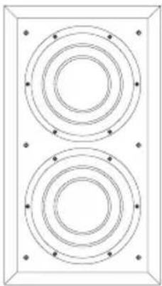
Description In wall subwoofer system with external rack-mount amplifier
Drive unit 2 × 0200mm (8 in) Paper/Kevlar
cone
Frequency range -6dB at 17Hz and 290Hz adjustable (EQ at A)
Frequency response ±3dB 21Hz - 200Hz adjustable (EQ at A)
Bass extension -6dB at 17Hz (position A)
-6dB at 21Hz (position B)
-6dB at 24Hz (position C)
Power Handling 200 watts 8 ohms (min 6.3 ohms)
Dimensions Height: 524mm (20.6 in)
Width: 294mm (11.6 in)
Depth: 93mm (3.7 in)
Depth with grille: 114mm (4.5 in)
Cut-out Height: 485mm (19.1 in)
Width: 255mm (10 in)
Net weight 6.4 kg (14.1 lb)
Finish
Frame/Grille
Semi-matt white suitable for
customising or pre-painting
Accessories Pre-mount kit for new construction
Back Box
Box Height: 1406 mm (55.4 in)
Width: 345 mm (13.6 in)
Depth: 86 mm (3.4 in)
Net Weight 9.6 kg (21.2 lb)
Material MDF

SA250
Description Dedicated Inwall Subwoofer rack-mount single channel 250W amplifier
Amplifier functions Front panel controls:
Rotary volume (line in)
Rotary low-pass filter frequency (4th-order Linkwitz, 40Hz - 140Hz)
Low-pass filter defeat 2-position switch
Phase 0/180 2-position switch
Bass extension 3-position switch
Movie/music EQ 2-position switch
On/auto/standby 3-position switch
Status LED
Fault LED
Amplifier inputs Line In (XLR & RCA Phono)
1x RCA phono socket, line in
1x RCA phono socket, link out
1x XLR socket, line in
1x XLR socket, link out
3.5mm jack - 12V trigger on/standby (overrides manual standby setting)
3.5mm jack - 12V trigger equalization movie/music
Amplifier outputs 1x Speakon 4-pole speaker socket
2x pair of Binding Posts
Amplifier power output 250W
Input impedance 33kΩ
Signal/noise >80dB
Rated power 95W
Consumption (1/8) 30W - Idling
3W - Standby
Dimensions Height: 100mm (3.9 in) [88.5mm (3.5 in) plus feet]
Width: 430mm (16.9 in)
Depth: 322mm (12.7 in)
Front panel Height: 2U 88.1mm/3.5 in
Net weight 5.4kg (11.9 lb)
Finish Black
Bowers & Wilkins
B&W Group Ltd
Dale Road
Worthing West Sussex
BN11 2BH England
T+44(0)1903221800
F+44(0)1903221801
info@bwgroup.com
www.bowers-wilkins.com
B&W Group (UK Sales)
T+441903221500
Euksales@bwgroup.com
B&W Group North America
T +1 978 664 2870
E marketing@bwgroupusa.com
B&W Group Asia Ltd
T+85234729300
E info@bwgroup.hk
Kevlar is a registered trademark of DuPont.
Speakon is a registered trademark of Neutrik AG.
Copyright © B&W Group Ltd. E&OE
Printed in China.