ASW850 - Subwoofer BOWERS & WILKINS - Free user manual and instructions
Find the device manual for free ASW850 BOWERS & WILKINS in PDF.
| Product Type | Active Subwoofer |
| Brand | Bowers & Wilkins |
| Model | ASW850 |
| Amplification | Built-in |
| Power Supply | 100-230 V, 50/60 Hz |
| Operating Modes | On, Auto, Standby |
| Available Settings | Volume, Crossover Frequency (low-pass filter), Phase (0°/180°), Equalization (positions A and B) |
| Connectivity | RCA inputs, speaker-level inputs (4 mm), line outputs (Link Out) |
| LED Indicator | Green (active), Red (standby) |
| Feet and Spikes | 4 rubber feet and 4 decoupling spikes with nuts supplied |
| Maintenance | Soft dry cloth; washable grille with soft brush |
| Safety | Protective fuse, earthing not required, do not expose to moisture |
| Warranty | 5 years for the speaker, 2 years for electronic components |
| Included Accessories | 4 rubber feet, 4 decoupling spikes, 4 nuts, international warranty card |
| Recommended Use | Home theater and 2-channel stereo |
Frequently Asked Questions - ASW850 BOWERS & WILKINS
User questions about ASW850 BOWERS & WILKINS
0 question about this device. Answer the ones you know or ask your own.
Ask a new question about this device
Download the instructions for your Subwoofer in PDF format for free! Find your manual ASW850 - BOWERS & WILKINS and take your electronic device back in hand. On this page are published all the documents necessary for the use of your device. ASW850 by BOWERS & WILKINS.
USER MANUAL ASW850 BOWERS & WILKINS
natural_image
Close-up of a metallic object resembling a stylized flower or abstract shape against a black background (no text or symbols visible)Figure 1
natural_image
Diagram showing three boxes with curved arrows indicating rotation or movement, next to a black box on a stand (no text or symbols)Figure 2
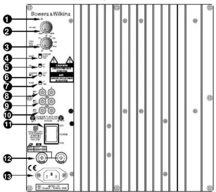
Figure 3
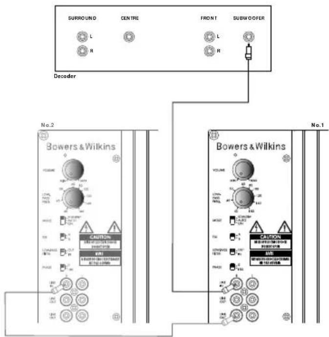
Figure 4
flowchart
graph TD
    A["Pre-Amplifier"] -->|LINE OUT L R| B["Line IN L R"]
    C["SPEAKERS OUT R L"] -->|SPEAKERS OUT SWEER OUT| B
    D["Bowers & Wilkins"] -->|NO.1| E["Line IN"]
    F["Line OUT"] -->|R| G["Line IN"]
    H["Line IN"] -->|L| I["Line IN"]
    J["Line IN"] -->|R| K["Line IN"]
    style A fill:#f9f,stroke:#333
    style C fill:#f9f,stroke:#333
    style D fill:#ccf,stroke:#333
    style F fill:#ccf,stroke:#333
    style B fill:#ccf,stroke:#333
    style E fill:#ccf,stroke:#333
    style G fill:#ccf,stroke:#333
    style H fill:#ccf,stroke:#333
    style I fill:#ccf,stroke:#333
    style J fill:#ccf,stroke:#333
    style K fill:#ccf,stroke:#333
Figure 5
flowchart
graph TD
    A["Pre-Amplifier"] --> B["LINE OUT L R"]
    C["Bowers & Wilkins"] --> D["Line IN L R"]
    E["SPEAKERS OUT R L"] --> F["Line IN"]
    G["Bowers & Wilkins"] --> H["Line IN"]
    I["Line IN"] --> J["Power Amplifier"]
    K["Line IN"] --> L["Power Amplifier"]
    M["Line IN"] --> N["Power Amplifier"]
    O["Line IN"] --> P["Power Amplifier"]
    Q["Line IN"] --> R["Power Amplifier"]
    S["Line IN"] --> T["Power Amplifier"]
    U["Line IN"] --> V["Power Amplifier"]
    W["Line IN"] --> X["Power Amplifier"]
    Y["Line IN"] --> Z["Power Amplifier"]
    AA["Line IN"] --> AB["Power Amplifier"]
    AC["Line IN"] --> AD["Power Amplifier"]
    AE["Line IN"] --> AF["Power Amplifier"]
    AG["Line IN"] --> AH["Power Amplifier"]
    AI["Line IN"] --> AJ["Power Amplifier"]
    AK["Line IN"] --> AL["Power Amplifier"]
    AM["Line IN"] --> AN["Power Amplifier"]
    AO["Line IN"] --> AP["Power Amplifier"]
    AQ["Line IN"] --> AR["Power Amplifier"]
    AS["Line IN"] --> AT["Power Amplifier"]
    AU["Line IN"] --> AV["Power Amplifier"]
    AW["Line IN"] --> AX["Power Amplifier"]
Contents
English
Limited Warranty......2
Owner's Manual......2
Français
This product has been designed and manufactured to the highest quality standards. However, if something does go wrong with this product, B&W
Loudspeakers and its national distributors warrant free of charge labour (exclusion may apply) and replacement parts in any country served by an official B&W distributor.
This limited warranty is valid for a period of five years from the date of purchase or two years for electronics including amplified loudspeakers.
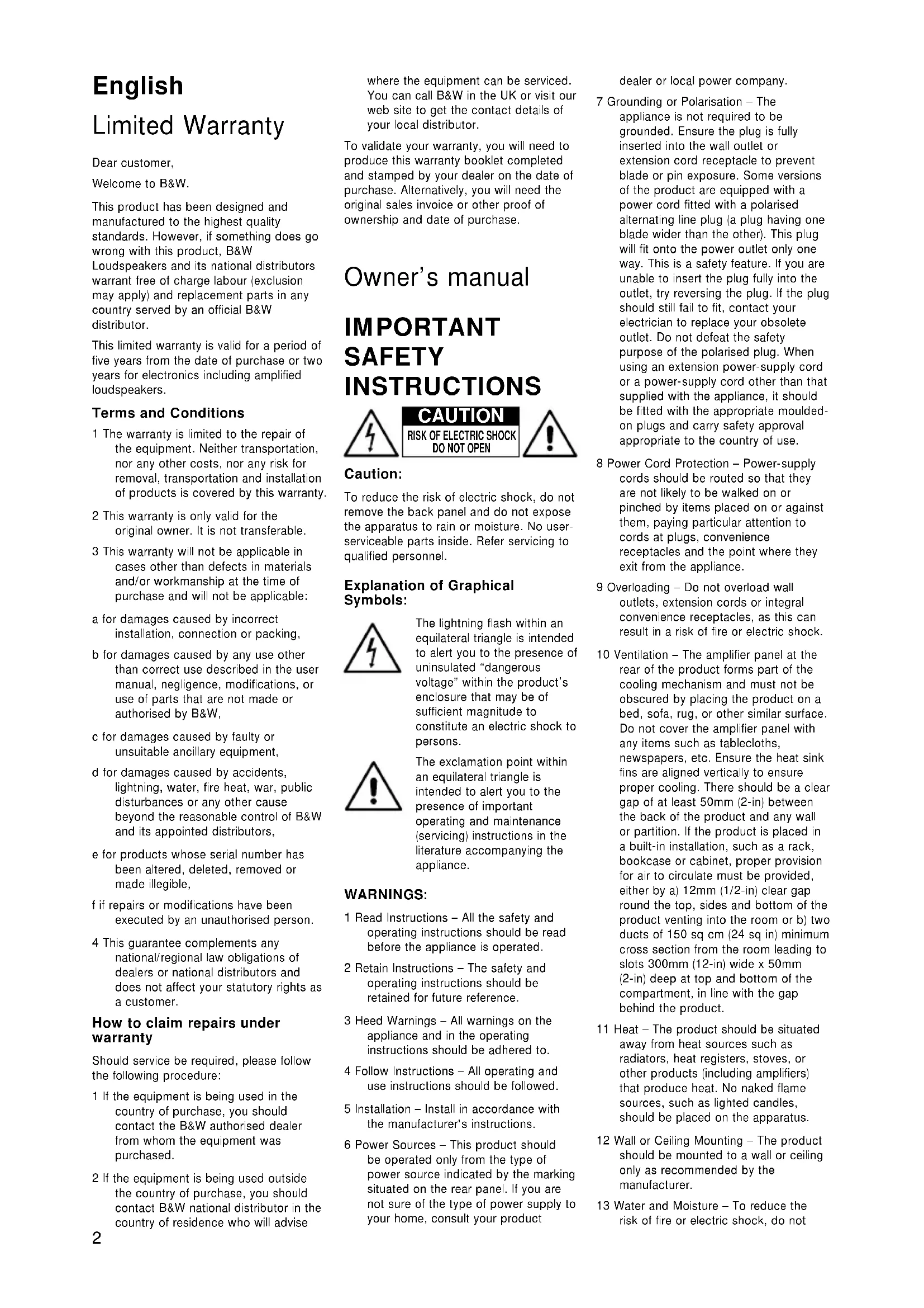
Terms and Conditions
1 The warranty is limited to the repair of the equipment. Neither transportation, nor any other costs, nor any risk for removal, transportation and installation of products is covered by this warranty.
2 This warranty is only valid for the original owner. It is not transferable.
3 This warranty will not be applicable in cases other than defects in materials and/or workmanship at the time of purchase and will not be applicable:
a for damages caused by incorrect installation, connection or packing,
b for damages caused by any use other than correct use described in the user manual, negligence, modifications, or use of parts that are not made or authorised by B&W,
c for damages caused by faulty or unsuitable ancillary equipment,
d for damages caused by accidents, lightning, water, fire heat, war, public disturbances or any other cause beyond the reasonable control of B&W and its appointed distributors,
e for products whose serial number has been altered, deleted, removed or made illegible,
f if repairs or modifications have been executed by an unauthorised person.
4 This guarantee complements any national/regional law obligations of dealers or national distributors and does not affect your statutory rights as a customer.
How to claim repairs under warranty
Should service be required, please follow the following procedure:
1 If the equipment is being used in the country of purchase, you should contact the B&W authorised dealer from whom the equipment was purchased.
2 If the equipment is being used outside the country of purchase, you should contact B&W national distributor in the country of residence who will advise
where the equipment can be serviced. You can call B&W in the UK or visit our web site to get the contact details of your local distributor.
To validate your warranty, you will need to produce this warranty booklet completed and stamped by your dealer on the date of purchase. Alternatively, you will need the original sales invoice or other proof of ownership and date of purchase.
Owner's manual
IMPORTANT SAFETY INSTRUCTIONS
CAUTION RISK OF ELECTRIC SHOCK DO NOT OPEN

Caution:
To reduce the risk of electric shock, do not remove the back panel and do not expose the apparatus to rain or moisture. No user-serviceable parts inside. Refer servicing to qualified personnel.
Explanation of Graphical Symbols:
The lightning flash within an equilateral triangle is intended to alert you to the presence of uninsulated “dangerous voltage” within the product’s enclosure that may be of sufficient magnitude to constitute an electric shock to persons.

The exclamation point within an equilateral triangle is intended to alert you to the presence of important operating and maintenance (servicing) instructions in the literature accompanying the appliance.
WARNINGS:
1 Read Instructions – All the safety and operating instructions should be read before the appliance is operated.
2 Retain Instructions – The safety and operating instructions should be retained for future reference.
3 Heed Warnings – All warnings on the appliance and in the operating instructions should be adhered to.
4 Follow Instructions – All operating and use instructions should be followed.
5 Installation – Install in accordance with the manufacturer's instructions.
6 Power Sources – This product should be operated only from the type of power source indicated by the marking situated on the rear panel. If you are not sure of the type of power supply to your home, consult your product
dealer or local power company.
7 Grounding or Polarisation – The appliance is not required to be grounded. Ensure the plug is fully inserted into the wall outlet or extension cord receptacle to prevent blade or pin exposure. Some versions of the product are equipped with a power cord fitted with a polarised alternating line plug (a plug having one blade wider than the other). This plug will fit onto the power outlet only one way. This is a safety feature. If you are unable to insert the plug fully into the outlet, try reversing the plug. If the plug should still fail to fit, contact your electrician to replace your obsolete outlet. Do not defeat the safety purpose of the polarised plug. When using an extension power-supply cord or a power-supply cord other than that supplied with the appliance, it should be fitted with the appropriate moulded-on plugs and carry safety approval appropriate to the country of use.
8 Power Cord Protection – Power-supply cords should be routed so that they are not likely to be walked on or pinched by items placed on or against them, paying particular attention to cords at plugs, convenience receptacles and the point where they exit from the appliance.
9 Overloading – Do not overload wall outlets, extension cords or integral convenience receptacles, as this can result in a risk of fire or electric shock.
10 Ventilation – The amplifier panel at the rear of the product forms part of the cooling mechanism and must not be obscured by placing the product on a bed, sofa, rug, or other similar surface. Do not cover the amplifier panel with any items such as tablecloths, newspapers, etc. Ensure the heat sink fins are aligned vertically to ensure proper cooling. There should be a clear gap of at least 50mm (2-in) between the back of the product and any wall or partition. If the product is placed in a built-in installation, such as a rack, bookcase or cabinet, proper provision for air to circulate must be provided, either by a) 12mm (1/2-in) clear gap round the top, sides and bottom of the product venting into the room or b) two ducts of 150 sq cm (24 sq in) minimum cross section from the room leading to slots 300mm (12-in) wide x 50mm (2-in) deep at top and bottom of the compartment, in line with the gap behind the product.
11 Heat – The product should be situated away from heat sources such as radiators, heat registers, stoves, or other products (including amplifiers) that produce heat. No naked flame sources, such as lighted candles, should be placed on the apparatus.
12 Wall or Ceiling Mounting – The product should be mounted to a wall or ceiling only as recommended by the manufacturer.
13 Water and Moisture – To reduce the risk of fire or electric shock, do not
expose the product to rain or excessive moisture such as in a sauna or bathroom. Do not use this product near water – for example, near a bathtub, washbowl, kitchen sink, laundry tub, in a wet basement, or near a swimming pool and the like.
14 Object and Liquid Entry – Never push objects of any kind into this product through openings, as they may touch dangerous voltage points or short out parts that could result in a fire or electric shock. Never spill liquid of any kind on the product. Do not place any object containing liquid on top of the product.
15 Cleaning – Unplug the product from the wall outlet before cleaning. The cabinet of the subwoofer may be cleaned by dusting with a dry cloth. If you wish to use an aerosol cleaning spray, do not spray directly on the cabinet; spray onto the cloth. Remove the grille first so that the cloth does not become stained, but be careful not to disturb the drive unit. The grille itself may be cleaned using a soft brush.
16 Attachments – Do not use attachments not recommended by the product manufacturer, as they may cause hazards.
17 Accessories – Do not place this product on an unstable cart, stand, tripod, bracket or table. The product may fall, causing serious injury to a child or adult, and serious damage to the product. Use only with a cart, stand, tripod, bracket or table recommended by the manufacturer or sold with the product. Any mounting of the product should follow the manufacturer's instructions and should use a mounting accessory recommended by the manufacturer.
18 Moving the appliance – A product and cart combination should be moved

with care. Quick stops, excessive force and uneven surfaces may cause the product and cart combination to
overturn. Check that there are no cables under the carpet that may be damaged by the spike feet. Do not walk the product on the spike feet as this may cause them to become detached from the cabinet and cause damage. Take care not to impale yourself with the spike feet.
19 Non-use Periods – The power cord of the appliance should be unplugged from the outlet during lightning storms or when the apparatus is left unused for a long period of time.
20 Servicing – Do not attempt to service this product yourself, as opening or removing covers may expose you to dangerous voltage or other hazards. Refer all servicing to qualified service personnel.
21 Damage Requiring Service – Unplug this product from the wall outlet and refer servicing to qualified personnel under the following conditions:
a When the power-supply cord or plug has been damaged.
b If liquid has been spilled or objects have fallen into the appliance.
c If the product has been exposed to rain or water.
d If the product does not operate normally by following the operating instructions. Adjust only those controls that are covered by the operating instructions, as an improper adjustment of other controls may result in damage and will often require extensive work by a qualified technician to restore the product to its normal operation.
e If the product has been dropped, or damaged in any way.
f When the product exhibits a distinct change in performance – this indicates a need for service.
22 Replacement Parts – When replacement parts are required, be sure the service technician has used replacement parts specified by the manufacturer or have the same characteristics as the original part. Unauthorised substitutions may result in fire, electric shock or other hazards.

23 Mains Fuses – For continued protection against fire hazard, use fuses only of the correct type and rating. The amplifier is designed to operate with nominal mains supplies in the range 100V to 230V AC, but different types of fuse are used, dependent on the mains voltage. The correct fuse specification for each voltage range is marked on the product.
24 Safety Check – Upon completion of any service or repairs to this product, ask the service technician to perform safety checks to determine that the product is in proper operating condition.
25 Magnetic Fields – the product creates a stray static magnetic field. Do not place any object that may be damaged by this magnetic field (eg cathode ray tube televisions or computer monitors, audio and video tapes and swipe cards) within 0.5m (2 feet) of the appliance. The appliance may cause distortion of cathode ray tube images beyond this distance.
Introduction
Thank you for purchasing a B&W ASW Active Subwoofer.
Since its foundation in 1966, the continuing philosophy of B&W has been the quest for perfect sound reproduction. Inspired by the company's founder, the late John Bowers, this quest has entailed not only high investment in audio technology and innovation but also an abiding appreciation of music and the demands of film sound to ensure that the technology is put to maximum effect.
This subwoofer has been designed for Home Theatre installations and to augment the bass performance of full-range speakers in 2-channel audio use. Adding the subwoofer to your system not only extends the bass to lower frequencies, it improves the midrange clarity by reducing the low-frequency demands on your existing speakers.
Please read through this manual fully before using the subwoofer. All sound installations require some planning and experimentation if you are to get the best out of the products used and this manual will guide you in this process.
As the subwoofer is connected to the electricity power supply, it is important that you familiarise yourself with the safety instructions and heed all warnings.
Keep this manual in a safe place for future reference.
B&W products are distributed to over 60 countries worldwide and we maintain an international network of carefully chosen and dedicated distributors. If you have a problem, which your dealer cannot resolve, our distributors will be more than willing to assist you.
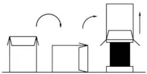
Unpacking
(figure 1)
The easiest way to unpack the subwoofer and avoid damage is as follows:
- Open the carton flaps right back and invert the carton and contents.
- Lift the carton away from the product.
We recommend that you retain the packaging for future use.
In addition to this manual, the carton should contain:
1 Subwoofer
1 Accessory pack containing:
4 Rubber feet
4 Spike feet
4 Lock nuts
1 International warranty document
A tour of the subwoofer (figure 2)
1 Power/Standby indicator
2 VOLUME control
3 LOW-PASS FREQUENCY control
4 MODE On/Auto/Standby switch
6 LOW-PASS FILTER defeat switch
7 Phase switch
8 LINE IN
9 LINE OUT
10 LINK OUT
11 POWER on/off switch
12 Fuse holders
13 Power input socket
Positioning the subwoofer
Because the subwoofer produces only low-frequency sounds, positioning is less critical in some respects compared to full-range speakers. Directional information is much less precise and you have more choice where to place the speakers to good effect. This said, best results are obtained if the subwoofer is placed between the satellite speakers or in the vicinity of one of them. If you use two subwoofers, it is best to put one near each satellite speaker.
Placing the subwoofer behind the listeners, even in surround sound installations, generally gives inferior imaging, but may be an acceptable compromise if domestic considerations dictate.
As with all speakers, the proximity of room boundaries affects the sound. Bass is generally increased as more surfaces come into close proximity with the speakers. Unlike full-range speakers, however, you can always restore the correct overall system balance by adjusting the volume level of the subwoofer. The more boost you get from the room, the less hard the speaker has to work; but there is a down side. Corner positions often excite more low-frequency room resonances, making the bass more uneven with frequency. There is no substitute for experiment as all rooms behave differently, so try the subwoofer in a variety of positions before making a final decision. A piece of music with a bass line ascending or descending the musical scale is useful for assessing the smoothness of the bass response. Listen for exaggerated or quiet notes. Having a separate subwoofer does enable you to optimise for room resonances independently from siting the satellite speakers for best imaging.
If the subwoofer is to be used in a confined space (eg in custom furniture), the space must be ventilated to allow sufficient air to circulate and cool the unit. Ask your dealer for advice.
The subwoofer is supplied with four spike feet. The spikes pierce through carpet pile, giving a firm support directly to the floor surface without crushing the pile.
If the unit is to be placed on a vulnerable surface, such as a wooden floor, either place a protective disc under each spike or fit the four rubber feet in place of the spikes.
When fitting either the rubber feet or the spike feet, first screw the lock nuts fully onto the thread and then screw the feet fully onto the threaded inserts in the base of the cabinet. If the unit rocks, loosen the relevant two opposing feet until the support is firm, then re-tighten the lock nuts to the inserts.
Check that there are no cables under the carpet that may be damaged by the spike feet.
Do not walk the product on the spike feet as this may cause them to become detached from the cabinet and cause damage.
Take care not to impale yourself with the spike feet when moving the product.
Electrical connections
Disconnect all sound system equipment from the power supply until the signal connections have been made and checked. This avoids the risk of damage whilst connections are made or broken.
The function of the subwoofer is to receive signals from the amplification chain and, where necessary for 2-channel audio, split the signal into low bass and higher frequencies and feed the latter back out to the satellite speakers. Left and right channel inputs may be combined into a single mono low bass feed to the subwoofer drive unit if required.
The subwoofer will input and output line-level signals via the RCA Phono sockets located on the back panel.
Use the following table to select the correct wiring method for your installation:
Application: Home Theatre
The subwoofer may be used with any decoder that has a line-level subwoofer output (normally from an RCA Phono socket). Most decoders with integral power amplifiers still output the subwoofer or Low-Frequency Effects (LFE) signal at line level.
- Decoder with one or more subwoofers - fig. 3
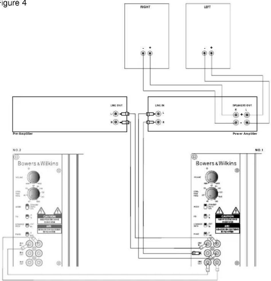
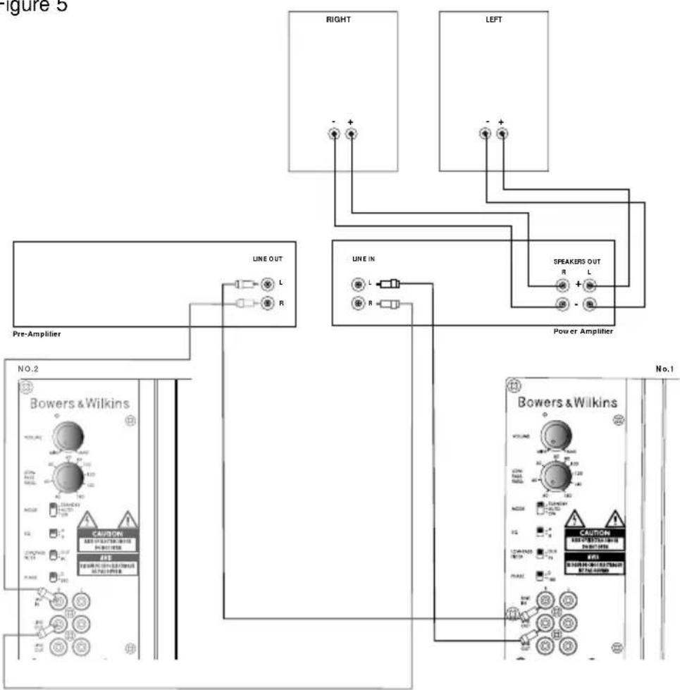
Application: 2-channel audio
Separate pre- & power amplifiers:
a One or more subwoofers with output combined into a single mono signal - fig. 4
b Two subwoofers with separate left and right signal - fig. 5
The subwoofer is not suitable for use with 2-channel integrated pre/power amplifiers.
Using more than one subwoofer
Using more than one unit in a single installation can improve performance in the following ways:
- Maintain stereo separation to the lowest frequencies.
- Cope with larger listening rooms.
- Enable greater maximum sound output – often useful for effectively reproducing special effects in Home Theatre applications.
- Smooth out the effects of low-frequency room resonances.
If you are using two subwoofers for 2-channel audio, separation is improved if each channel has its own subwoofer, providing each one is placed close to the relevant satellite speaker. Only use the mono connection of figure 4 if you cannot place each subwoofer close to its satellite speaker.
Double-check the connections
Before auditioning the sound quality of your new installation and fine-tuning it, double-check the connections. All too often, users complain that they cannot get a decent sound however they set the controls, only
to discover something has been wrongly connected. Make sure that:
- The phasing is correct – there should be no positive to negative connections to the satellite speakers. If something is out of phase you may get a fuzzy sound with an imprecise and floating image, a lack of bass or a combination of the two.
- There are no left to right mix-ups – this can result, for example, in the orchestra being the wrong way round or, more disastrously, sounds on your Home Theatre going in the opposite direction to the action on the screen.
Switching on and off
We recommend that you switch the subwoofer on before any power amplifiers receiving signals from the subwoofer. Similarly, when switching off, switch the subwoofer off last.
The MODE standby/auto/on switch (4) does not isolate the amplifier completely from the power supply. It maintains a low-power input to an auxiliary sensing circuit.
The switch (4) operates as follows:
On:
With the switch in this position, the amplifier remains permanently on, and the light (1) glows green.
Auto:
On first switching the subwoofer to Auto, the amplifier becomes fully active and the light (1) glows green. After a period of about 5 minutes without an input signal, the amplifier automatically reverts to standby mode, and the light glows red. When an input signal is detected, the amplifier automatically becomes fully active and the light glows green.
Standby:
In this position, the amplifier is in permanent standby, and the light glows red.
If the subwoofer is to be out of use for an extended period of time, we recommend you isolate it from the power supply, either by using the POWER switch (11) or by removing the plug from the power socket.
Setting the controls
There are 5 controls to consider:
• The VOLUME control (2)
• The LOW-PASS FREQUENCY control (3)
• The PHASE switch (7)
• The LOW-PASS FILTER switch (6)
• The EQ (equalisation) switch (5)
The optimum settings depend on the other equipment used with the subwoofer. If using more than one subwoofer, ensure the controls on each one are set the same.
Use with home theatre decoders
The B&W ASW Active Subwoofer is not a THX® licensed component, but may be used with a THX® controller if desired.
- Set the decoder VOLUME control to
the half way (12 o'clock) position.
- The setting of the LOW-PASS FREQUENCY control is irrelevant.
- Set the PHASE switch initially to 0'.
- Set the LOW-PASS FILTER switch to OUT.
- Set the EQ switch initially to position A. See also the section "Fine tuning".
If you have a THX® controller, ensure that the subwoofer function is enabled. When so configured it incorporates all the filtering and level setting required for the subwoofer in all modes. For level calibration, the internal test noise and channel level controls in the THX® controller should be used. In all cases the levels should be set to obtain 75dB SPL (C-weighted) at the listening position from the controller's internal noise test signal.
With other decoders, configure the front and surround speakers to "large" or "small" as appropriate before setting the levels. Use the internal noise test signal and volume controls of the decoder to set the levels of all the speakers. Only change the VOLUME control on the subwoofer if there is not enough range in the decoder to achieve the correct levels.
Inexpensive sound level meters are readily available from electronics stores and should be used to calibrate the levels. Refer to your decoder manual for further details on how to set the levels.
Use for 2-channel audio
- Set the VOLUME control initially to the half way (12 o'clock) position.
- Set the LOW-PASS FREQUENCY initially to 80Hz.
- Set the LOW-PASS FILTER switch to IN.
- Set the EQ switch initially to position A.
- Set the PHASE switch initially to 0'.
See also the section "Fine tuning".
Fine-tuning
There are two settings of the EQ switch. Position B is optimised to allow the subwoofer to provide the highest listening levels, while position A gives greater bass extension coupled with a tighter sound.
2-channel audio
The optimum settings of the PHASE switch and the LOW-PASS FREQUENCY control are inter-related and also dependent on the low-frequency cut-off characteristic of the satellite speakers and the relative positions of all the speakers in the installation.
Set the system up in the preferred position and play some programme with a steady bass content. The optimum setting for the LOW-PASS FREQUENCY depends on several variables; the bass performance and power handling of the satellite speakers, the number of subwoofers used and their position relative to the satellite speakers. The range 80 – 90Hz is a good starting point for the LOW-PASS frequency. Unless two subwoofers are used to
preserve separate right and left channel information and are sited close to the relevant satellite speakers, using a higher cut-off frequency may compromise the stereo image and should only be considered if the bass performance of the satellite speakers is particularly limited.
At each setting of the cut-off frequency, listen with the phase switch in both positions. The correct one is that which gives the fullest bass and that will depend on the bass characteristics of your satellite speakers and the relative distances of the subwoofer(s) and the satellite speakers to the listeners. When using more than one subwoofer, ensure that each one has its cut-off frequency and phase switch set the same way.
Set the loudness of the subwoofer relative to the satellite systems to your liking. Use a wide variety of programme material to get an average setting. One that sounds impressive on one piece may sound overpowering on another. Listen at realistic levels as the perception of balance varies with sound level.
Home theatre
The situation with home theatre is somewhat different from 2-channel audio. The subwoofer (LFE) signal is a separate channel rather than an extension of the signal to the satellite speakers. The LOW-PASS filter is switched out, because the decoder provides all the filtering for any speakers set to "small". However, the position of the phase switch must still be assessed. Normally the phase will be set to 0^ , but if the subwoofer is positioned at a distance significantly different from the other speakers, or the power amplifier driving the other speakers happens to invert the signal, the 180^ position may be preferable. Listen with the switch in both positions and choose the one that gives the fullest sound. If there is little difference, leave the switch at 0^ .
Decoders normally have a calibrated noise signal that can be used to set the relative levels of all the speakers, making the task somewhat more straightforward than for 2-channel audio. However, do not be afraid to alter the settings to your personal preference. It is all too easy to get carried away with the capabilities of the subwoofer, especially with some special low-frequency effects. Often a more realistic portrayal, and one more satisfying in the long term, is to be had by setting the subwoofer level lower that the standard calibration level.
All applications
If you get problems with lumpy bass – if certain bass notes are exaggerated more than others – then you probably have a room interface problem and it is worth experimenting with the placement of the subwoofer. What may seem like small changes in position – 15cm (6in) or so – can have a profound effect on the sound. Try raising the subwoofer clear of the floor as well as lateral movement. The use of multiple subwoofers can smooth the effects of room resonances, as each subwoofer will tend to excite resonances at different frequencies. If you alter the relative
distances from the subwoofer(s) and satellite speakers to the listeners appreciably, reassess the phase switch setting. You should also check the level setting of the subwoofer (using either the decoder output levels or the volume control on the subwoofer amplifier as appropriate), but only after setting the phase correctly.
Taking care of the subwoofer
The cabinet of the subwoofer may be cleaned by dusting with a dry cloth. If you wish to use an aerosol cleaning spray, do not spray directly on the cabinet; spray onto the cloth. Remove the grille first so that the cloth does not become stained, but be careful not to disturb the drive unit. The grille itself may be cleaned using a soft brush.
Do not use the subwoofer as a table. When in use, objects left on top of the subwoofer are liable to rattle. In particular, avoid the risk of liquids being spilled (eg from drinks or vases of flowers).
If the system is taken out of use for a long period, disconnect the subwoofer from the power supply.
Note: The subwoofer will automatically shut down if driven excessively. If this occurs, re-set the subwoofer by turning it off then on again, using the power on/off switch on the amplifier panel.
Français
Garantie limitée
Cher Client,
Bienvenue à B&W.
RISQUE D'ÉLECTROCUTION NE PAS OUVRIR

Attention :
The source image is illegible due to extreme pixelation and distortion. No characters, symbols, or structured content can be reliably extracted. Therefore, no OCR text can be generated that matches the visual content of the source image.
的 国家二一 中国国家
サブウーファーの背景
警告:
natural_image
Technical line drawing of a speaker or speaker with concentric circular components and mounting holes (no text or symbols)ASW800
natural_image
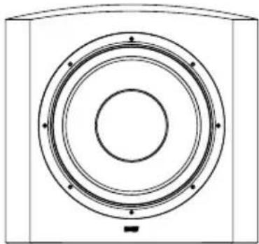
Technical line drawing of a speaker or speaker with concentric circles and mounting holes (no text or symbols)ASW850
| Description | Active closed-box subwoofer system | Active closed-box subwoofer system |
| Drive units | 300mm (12 in) paper/Kevlar® cone long-throw | 380mm (15 in) paper/Kevlar® cone long-throw |
| System frequency range | -6dB at 15Hz and 40/140Hz adjustable (EQ at A) | -6dB at 14Hz and 40/140Hz adjustable (EQ at A) |
| System frequency response | -3dB 20Hz - 31/110Hz adjustable (EQ at A) | ±3dB 18Hz - 31/110Hz adjustable (EQ at A) |
| Amplifier | Power output: 1000W continuousInput impedance: 33kΩSignal / noise: >90dBFunctions: Input levelLow-pass filter frequencyLow-pass filter bypassBass roll-off alignmentAuto sense on/standbyPhase switchInputs: Line In (RCA Phono)Outputs: Line Out (RCA Phono)high-passedLink Out (RCA Phono) | Power output: 1000W continuousInput impedance: 33kΩSignal / noise: >90dBFunctions: Input levelLow-pass filter frequencyLow-pass filter bypassBass roll-off alignmentAuto sense on/standbyPhase switchInputs: Line In (RCA Phono)Outputs: Line Out (RCA Phono)high-passedLink Out (RCA Phono) |
| Low-Pass Filter | Active 2nd-order, variable cut-off frequency | Active 2nd-order, variable cut-off frequency |
| High-Pass Filter | Active 3rd-order -6dB at 80Hz | Active 3rd-order -6dB at 80Hz |
| Dimensions | Height: 529mm (20.8 in) not including feetWidth: 476mm (18.7 in)Depth: 351mm (13.8 in)including grille and controls | Height: 529mm (20.8 in) not including feetWidth: 562mm (22.1 in)Depth: 522mm (20.6 in)including grille and controls |
| Net Weight | 35kg (77 lb) | 45kg (99 lb) |